

Page 1

300Mbps Wireless-N Guest WiFi
Access Point / Account Generator 2T2R 2.4GHz
R300WN22GAxx
*actual product may vary from photos
DE: Bedienungsanleitung - de.startech.com
FR: Guide de l'utilisateur - fr.startech.com
ES: Guía del usuario - es.startech.com
IT: Guida per l'uso - it.startech.com
NL: Gebruiksaanwijzing - nl.startech.com
PT: Guia do usuário - pt.startech.com
For the most up-to-date information, please visit: www.startech.com
Manual Revision: 09/08/2014
Page 2

FCC Compliance Statement
This equipment has been tested and found to comply with the limits for a Class B digital
device, pursuant to part 15 of the FCC Rules. These limits are designed to provide reasonable
protection against harmful interference in a residential installation. This equipment
generates, uses and can radiate radio frequency energy and, if not installed and used in
accordance with the instructions, may cause harmful interference to radio communications.
However, there is no guarantee that interference will not occur in a particular installation. If
this equipment does cause harmful interference to radio or television reception, which can
be determined by turning the equipment o and on, the user is encouraged to try to correct
the interference by one or more of the following measures:
• Reorient or relocate the receiving antenna.
• Increase the separation between the equipment and receiver.
• Connect the equipment into an outlet on a circuit dierent from that to which the
receiver is connected.
• Consult the dealer or an experienced radio/TV technician for help
This device complies with part 15 of the FCC Rules. Operation is subject to the following
two conditions: (1) This device may not cause harmful interference, and (2) this device must
accept any interference received, including interference that may cause undesired operation.
Changes or modications not expressly approved by StarTech.com could void the user’s
authority to operate the equipment.
Industry Canada Statement
This Class B digital apparatus complies with Canadian ICES-003.
Cet appareil numérique de la classe [B] est conforme à la norme NMB-003 du Canada.
CAN ICES-3 (B)/NMB-3(B)
This device complies with Industry Canada licence-exempt RSS standard(s).
Operation is subject to the following two conditions:
(1) This device may not cause interference, and
(2) This device must accept any interference, including interference that may cause undesired
operation of the device.
Le présent appareil est conforme aux CNR d’Industrie Canada applicables aux appareils radio
exempts de licence.
L’exploitation est autorisée aux deux conditions suivantes:
(1) l’appareil ne doit pas produire de brouillage, et
(2) l’utilisateur de l’appareil doit accepter tout brouillage radioélectrique subi, même si le
brouillage est susceptible d’en compromettre le fonctionnement.
Instruction Manual
Page 3

IC Radiation Exposure Statement
This equipment complies with IC RSS-102 radiation exposure limit set forth for an
uncontrolled environment. This equipment should be installed and operated with minimum
distance 0.5cm between the radiator and your body.
Déclaration d’exposition à la radiation
Cet équipement respecte les limites d’exposition aux rayonnements IC dénies pour un
environnement non contrôlé. Cet équipement doit être installé et mis en marche à une
distance minimale de 0.5 cm qui sépare l’élément rayonnant de votre corps.
L’émetteur ne doit ni être utilisé avec une autre antenne ou un autre émetteur ni se trouver
à leur proximité.
FCC ID: TWS-GW-1
IC:11232A-R300WN22GA
The Country Code Selection feature is disabled for products marketed in the US/Canada
The device, for operation in the band 5150–5250 MHz is only for indoor use to reduce the
potential for harmful interference to co-channel mobile satellite systems.
Use of Trademarks, Registered Trademarks, and other Protected Names and Symbols
This manual may make reference to trademarks, registered trademarks, and other
protected names and/or symbols of third-party companies not related in any way to
StarTech.com. Where they occur these references are for illustrative purposes only and do not
represent an endorsement of a product or service by StarTech.com, or an endorsement of the
product(s) to which this manual applies by the third-party company in question. Regardless
of any direct acknowledgement elsewhere in the body of this document, StarTech.com hereby
acknowledges that all trademarks, registered trademarks, service marks, and other protected
names and/or symbols contained in this manual and related documents are the property of
their respective holders.
Instruction Manual
Page 4

Table of Contents
Introduction ............................................................................................1
Packaging Contents ................................................................................................................................. 1
Product Diagram ....................................................................................1
Product Overview ..................................................................................................................................... 1
LED Indicators............................................................................................................................................. 1
Installation ..............................................................................................2
Advanced Setup Menu ..........................................................................6
Management .............................................................................................................................................. 6
Security ......................................................................................................................................................... 17
System ........................................................................................................................................................... 21
Server............................................................................................................................................................. 26
Guest Setting .............................................................................................................................................. 30
Employee Setting ...................................................................................................................................... 42
System Status Menu ..............................................................................43
System Report ............................................................................................................................................ 43
Account List ................................................................................................................................................ 44
Account Log ................................................................................................................................................45
Current User Report ................................................................................................................................. 46
DHCP Clients Report ................................................................................................................................ 46
Session List .................................................................................................................................................. 47
System Tools Menu ................................................................................47
Instruction Manual
i
Page 5

Conguration ..........................................................................................47
Firmware Upgrade ....................................................................................................................................48
Boot Code .................................................................................................................................................... 51
System Account .........................................................................................................................................51
SSL Certicate ............................................................................................................................................. 52
PING .............................................................................................................................................................. 52
Restart ........................................................................................................................................................... 53
Logout ........................................................................................................................................................... 53
Specications ..........................................................................................54
Technical Support .................................................................................. 55
Warranty Information ............................................................................55
Instruction Manual
ii
Page 6
Introduction
Packaging Contents
• 1 x Guest WiFi Access Point / Account Generator
• 1 x Ethernet Cable
• 2 x Screws for Wall Mounting
• 1 x Power Adapter
• 1 x Quick Start Guide
• 1 x Instruction Manual CD
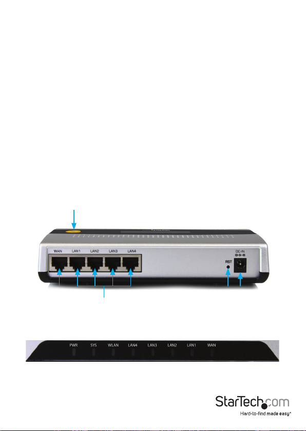
Product Diagram
Product Overview
Guest Accont
Generation Button
WAN/ Uplink
Port
LED Indicators
Instruction Manual
Reset Button DC Jack
LAN Ports
1
Page 7

LED State Description
PWR
SYS
WAN
LAN-1-4
WLAN
Installation
O No power
Green Unit powered on
O
Green
Green (Blinking)
O No network connection
Green
Green (Blinking) Indicates WAN activity
O No network connection
Green
Green (Blinking) Indicates LAN activity
O The Wireless is not ready
Green
Green (Blinking) Indicates Wireless activity
Remains o while the unit
is initializing
Initialization complete,
system is ready to use
During rmware
upgrades, this system LED
will blink
10/100Mbps network
connection established
10/100Mbps network
connection established
Wireless connection
established
1. The Access Point is designed to sit on a at surface (such as a desktop) or be securely
mounted to a wall or similar surface. If you wish to mount the device, rst prepare
the surface by installing mounting screws (not included) otherwise skip to Step 5.
Instruction Manual
2
Page 8

2. The distance between the two mounting sockets on the back of the Network Switch
is approximately 106mm. Mark the distance on the wall, making sure your marks are
straight and level.
3. Depending on the mounting surface, use the appropriate tools and hardware to
install mounting screws into the surface. There should be a gap of approximately 2
mm between the head of the screw and the wall surface.
4. Place the Access Point so that the wide openings of the mounting sockets are over
the screw heads. Slide the case downward so that the screw heads slide into the
narrow slots.
5. Connect an Ethernet cable from the WAN port on the Access Point (AP) to your ISP
modem (Cable, DSL, etc.).
6. Connect a second Ethernet cable from your computer to one of the LAN ports on
the AP.
7. Connect the power adapter to the DC jack on the AP and wait approximately 30
second for the unit to initialize.
Note: If the message Error: 0001 appears on the LCD screen, the AP did not detect a
connection on the WAN port, please check your cabling.
8. Open your preferred web browser, enter the IP address of the Access Point (Default:
10.59.1.200) into the address box and press Enter.
9. Login to the web GUI with your username / password (Default: admin / admin) and
click Login.
Instruction Manual
3
Page 9
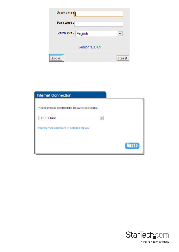
10. The Setup Wizard will bring you through the basic conguration requirements in
3 sections:
Internet – Allows you to select the appropriate Internet connection type for your
ISP
• DHCP Client – Allows the device to automatically obtain TCP/IP settings from
your ISP Modem.
• Static IP – Manually enter your desired IP address settings.
• PPPoE (Point-to-Point Protocol over Ethernet) – Typically used for ADSL ISPs
that require a username and password to connect
• PPTP Client (Point-to-Point Tunneling Protocol) – Typically used for European
ADSL ISPs that require a username and password to connect.
Instruction Manual
4
Page 10
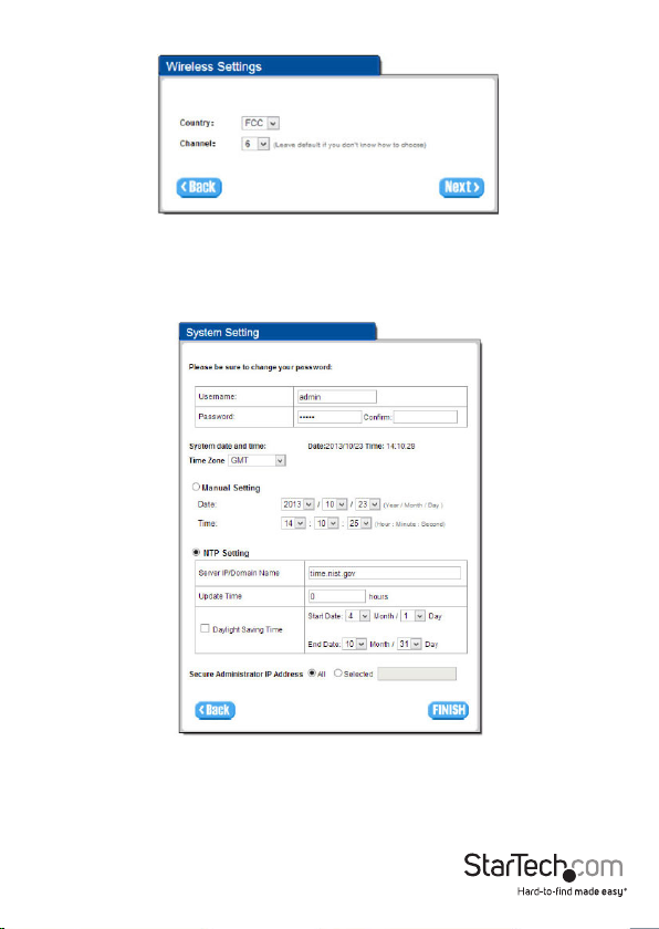
Wireless – Allows you to specify basic wireless network settings
• Country – Choose between ETSI (European Telecommunications Standards
Institute) or FCC (Federal Communications Commission – North America).
• Channel – Select the channel ID for wireless connection.
System – Allows you to specify basic system settings for the AP
• Username / Password – Change the default username and password.
NOTE: It is strongly recommended to change the default security settings, to
avoid unwanted access and/or conguration changes. Username and Password
can consist of up to 20 alphanumeric characters and is case sensitive.
Instruction Manual
5
Page 11
• System date and time – Specify the Time Zone and choose between manual
date and time entry or NTP server settings.
• Secure Administrate IP Address – Administrator can specify 5 IP addresses or a
range to allow remote control access from network.
11. Click Finish to complete the Setup Wizard.
12. Click the Advanced Setup tab on the top menu to further modify device settings.
Advanced Setup Menu
The Advanced Setup menu gives you access to all available device settings, so you can
congure the device to suit your network requirements.
Click the Apply button in the bottom right corner of each section to save your changes
(a restart of the device may be required for some changes).
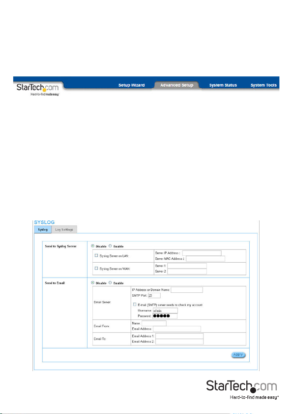
Management
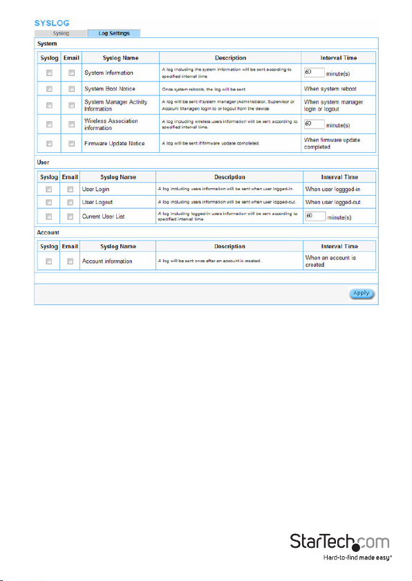
Syslog
The Syslog feature allows you to transmit event messages to your syslog server or
email address for monitoring and troubleshooting
Instruction Manual
6
Page 12

Item Default Description
Syslog Disable Enables or disables the syslog server function.
Syslog on LAN
Server IP Address Empty Enter your syslog server LAN IP address.
Server MAC
Address
Empty Enter your syslog server MAC address.
Syslog on WAN
Server 1 IP
Address
Server 2 IP
Address
Empty Enter the WAN IP address of your rst syslog server.
Empty
Enter the WAN IP address of your second syslog
server.
Send to Email Disable Enables or disables the send to e-mail function.
E-mail Server
IP Address or
Domain Name
Empty
Enter your SMTP server IP address or domain name
(max 50 characters).
SMTP Port 25 Acceptable SMTP port range is 25 or 2500 to 2599.
E-mail (SMTP)
Server needs to
Disable
check my account
Username Empty
If your SMTP server requires authentication before
accepting e-mail, enable this option. These values
(username and password) are supplied by your
network administrator, SMTP server provider or ISP.
Enter the username for your SMTP server (up to 64
characters).
Password Empty Enter the password for your SMTP server
Email From
Enter the name you would like to appear in the
Name Empty
“Message From” eld of your outgoing message
(max 20 characters).
Email Address Empty Enter a From email address.
Email To
Email Address 1 Empty Enter an email address to receive the logs.
Email Address 2 Empty
Enter a secondary e-mail address to receive the logs.
Instruction Manual
7
Page 13
Instruction Manual
8
Page 14

Item
System
System Information
System Boot Notice
Interval
Time
5~60
minutes
When
system
rebooted
Description
System information would be sent according to
specied interval time.
Format:
PRODUCT=GW-1;VER=2.00.00;LOGNAME=DVI;
DATE=07Mar26;TIME=11:30:00;
WANMAC=09-00-0e-00-00-01;LANMAC=09-000e-00-00-02; WLANMAC=09-00-0e-00-00-03;
IP_ADDRESS=210.66.37.21; SYS_UP_TIME=14D2
3H34M21S;WANTXOK=99999;
WANRXOK=99999;WANTXERROR=99999;WA
NRXERROR=99999; LANTXOK=99999;LANRX
OK=99999;LANTXERROR=99999; LANRXERRO
R=99999;WIRELESSTXOK=99999;WIRELESSRX
OK=99999; WIRELESSTXERROR=99999;WIRELES
SRXERROR=99999;
If device have been rebooted or restarted, the
log would be sent.
Format:
PRODUCT=GW-1;VER=2.00.00;LOGNAME=SUN;
DATE=07Mar26;TIME=15:23:32;
WANMAC=09-00-0e-00-00-01;LANMAC=09-000e-00-00-02;WLANMAC=09-00-0e-00-00-03;
IP_ADDRESS=210.66.37.21; SYS_NAME=Cafehot
spot;LOCATION=East;CITY=Taipei;
COUNTRY=Taiwan; FIRMWARE=v1.01.02;MESSA
GE=System_Up;
Message = System_Reboot
Instruction Manual
9
Page 15

System Manager
Activity Information
Wireless
Association
Information
Firmware Update
Notice
When
system
manager
login or
logout
5~60
minutes.
When
rmware
update
completed
A log will be sent if system manager
(Administrator) login to or logout from the
device.
Format:
PRODUCT=GW-1;VER=2.00.00;LOGNAME=SUN;
DATE=07Mar26;TIME=15:23:32;
WANMAC=09-00-0e-00-00-01;LANMAC=09-000e-00-00-02; WLANMAC=09-00-0e-00-00-03;
IP_ADDRESS=210.66.37.21;
SYS_NAME=Cafehotspot;LOCATION=East;CITY=
Taipei; COUNTRY=Taiwan; FIRMWARE=v1.01.02;
MESSAGE=System_Up;
Account Name = Admin
Status = Login | Logout | Idle_Time_Out
A log including wireless users information will
be sent according to specied interval time.
Format:
PRODUCT=GW-1;VER=2.00.00;LOGNAME=WAI;
DATE=07Mar26;TIME=15:23:32;
WANMAC=09-00-0e-00-00-01;LANMAC=09-000e-00-00-02; WLANMAC=09-00-0e-00-00-03;
IP_ADDRESS=210.66.37.21;
USER_NUM=15;SEQ=1-5;USER_MAC=02-343e-01-00;
A log will be sent if rmware update completed
Format:
PRODUCT=GW-1;VER=2.00.00;LOGNAME=FUN;
DATE=07Mar26;TIME=15:23:32;
WANMAC=09-00-0e-00-00-01;LANMAC=0900-0e-00-00-02; LANMAC=09-000e-00-00-03; IP_ADDRESS=210.66.37.21;
MESSAGE=Success;OLD_FRIMWARE=v1.00.01;
NEW_FIRMWARE=v1.00.02
Message = Success | Fail
Instruction Manual
10
Page 16

User
User Login
User Logout
When a
user logs
in
When user
loggedout
A log including users information will be sent
when a user logs in
Format:
PRODUCT=GW-1;VER=2.00.00;LOGNAME=ULI;D
ATE=07Mar26; TIME=15:23:32;WANMAC=09-000e-00-00-01;
LANMAC=09-00-0e-00-00-02; WLANMAC=0900-0e-00-00-03;
IP_ADDRESS=210.66.37.21;USER_
NAME=asdfg12;USER_IP=10.59.1.1; USER_
MAC=02-34-3e-01-00;INTERFACE=Ethernet;
USER_TYPE=Dynamic;
User Type = Guest/ Employee
A log including users information will be sent
when user logged –out
Format:
PRODUCT=GW-1;VER=2.00.00;LOGNAME=ULO
;DATE=07Mar26; TIME=15:23:32;WANMAC=0900-0e-00-00-01;
LANMAC=09-00-0e-00-00-02; WLANMAC=0900-0e-00-00-03;
IP_ADDRESS=210.66.37.21;USER_
NAME=asdfg12;USER_IP=10.59.1.1; USER_
MAC=02-34-3e-01-00;INTERFACE=Ethernet;
USER_TYPE=Dynamic;RXDATA=1234;
TXDATA=1234; USED_TIME=24:00:00;LOGOUT_
TYPE=Time_Up;TIME_LEFT=24:00:00
User Type = Guest/ Employee
Instruction Manual
11
Page 17

A log including logged-in users information will
be sent according to specied interval time
Format:
PRODUCT=GW-1;VER=2.00.00;LOGNAME=CUL
;DATE=07Mar26; TIME=15:23:32;WANMAC=0900-0e-00-00-01;
Current User List
.5~60
minutes.
LANMAC=09-00-0e-00-00-02; WLANMAC=0900-0e-00-00-03;
IP_ADDRESS=210.66.37.21;USER_
NUM=0;SEQ=1-5; USER_NAME=asdfg12,USER_
IP=10.59.1.2,USER_MAC=02-34-3e-01-00,
INTERFACE=Ethernet,USER_TYPE=Dynamic,RXDATA=1234,
TXDATA=1234,USED_
TIME=24:00:00,SESSION=100,WLAN_SIG=N/A;
Account
A log will be sent when an account is created
Format:
PRODUCT=GW-1;VER=2.00.00;LOGNAME=ACI;D
ATE=07Mar26; TIME=15:23:32;WANMAC=09-00-
Account
Information
When an
account is
created
0e-00-00-01;
LANMAC=09-00-0e-00-00-02;
WLANMAC=09-00-0e-00-00-03; IP_
ADDRESS=210.66.37.21;USER_NAME=asdfg12;
ACCOUNT_TYPE=TimetoFinish; ACCOUNT_
SERIAL=000002;
ACCOUNT_PRICE= USD20.00; ACCOUNT_
USAGE_TIME=10:59:59;
Session Trace
Session Trace is an intelligent function to help you trace user behavior. When Session
Trace is enabled, the system will collect information such as destination IP, destination
port, source IP, source MAC, source port from every user and send the collected
information in text le format to a specied TFTP server or Email Server.
Instruction Manual
12
Page 18
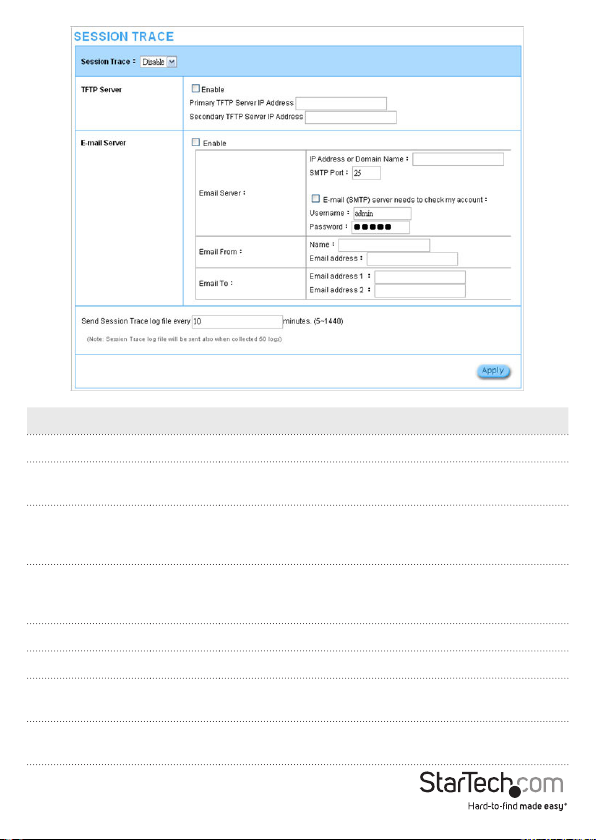
Item Default Description
Session Trace Disable Disables or enables session trace function.
Primary TFTP
Server IP Address
Empty Enter the IP address of the primary TFTP server.
Secondary
TFTP Server IP
Empty Enter the IP address of the secondary TFTP server.
Address
Send Session
Trace log le
every
10
minutes
Send the session trace log le at the specied
interval. Acceptable range is from 5 to 1440 minutes
Send to Email Disable Enables or disables the send to e-mail function.
E-mail Server
IP Address or
Domain Name
Empty
SMTP Port Empty
Enter the SMTP server IP address or domain name
(max 50 characters).
Acceptable SMTP port range is 25, or from 2500 to
2599.
Instruction Manual
13
Page 19
E-mail (SMTP)
Server needs
to check my
Disable
account
Username Empty
If your SMTP server requires authentication before
accepting e-mail, enable this option. These values
(username and password) are supplied by your
network administrator, SMTP server provider or ISP.
Enter the username for the SMTP server (max 64
characters).
Password Empty Enter the password for the SMTP server.
Email From
Enter the name you would like to appear in the
Name Empty
“message from” eld of your outgoing message
(max 20 characters).
Email Address Empty Enter a From email address.
Email To
Email Address 1 Empty Enter an email address to receive the logs.
Email Address 2 Empty Enter a secondary email address to receive the logs.
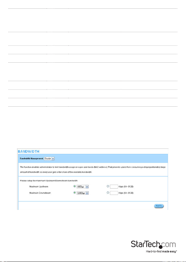
Bandwidth Management
The Bandwidth Management function enables you to limit bandwidth usage on a per
user basis (by MAC address), preventing users from consuming a disproportionately
large amount of bandwidth.
Instruction Manual
14
Page 20
Item Default Description
Bandwidth Disable
Enables or disables
Bandwidth Management.
Specify the max upstream
Maximum Upstream 64Kbps
bandwidth (64 – 5120
Kbps).
Specify the max
Maximum Downstream 128Kbps
downstream bandwidth
(64 – 5120 Kbps).
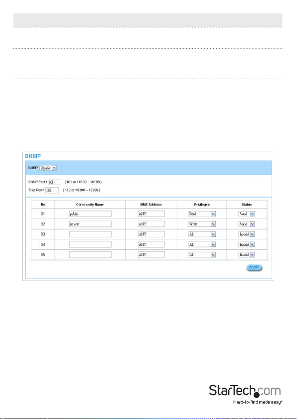
SNMP
The SNMP conguration menu allows you to access to your device via Simple Network
Management Protocol.
Instruction Manual
15
Page 21

Item Default Description
SNMP Disable Disables or enables SNMP management.
If SNMP is enabled, you can specify the
SNMP port number. The allowed SNMP
SNMP Port 161
port numbers are 161 (default), or from
16100-16199 and Trap port numbers are
162 (default), or from 16200-16299.
This Port setting is useful for remote control
Trap Port 162
via NAT.
Conguration
Every unit with SNMP enabled must be
congured to recognize one or more
Community Name Public/Private
community names (up to 20 characters).
The default setting for the community of
entry 1 is “public” and for the entry 2 is
“private” and others are empty.
NMS Address ANY
Privileges Read/Write
The address of the Network Management
Station.
Choose “Read”, “ Write”, “Trap Recipients” or
“All” for dierent privileges.
Choose “Valid” or “Invalid” to enable /
Status Valid/Invalid
disable the community entry. The default
setting of entry 1, 2 are valid and others are
invalid.
Instruction Manual
16
Page 22
Security
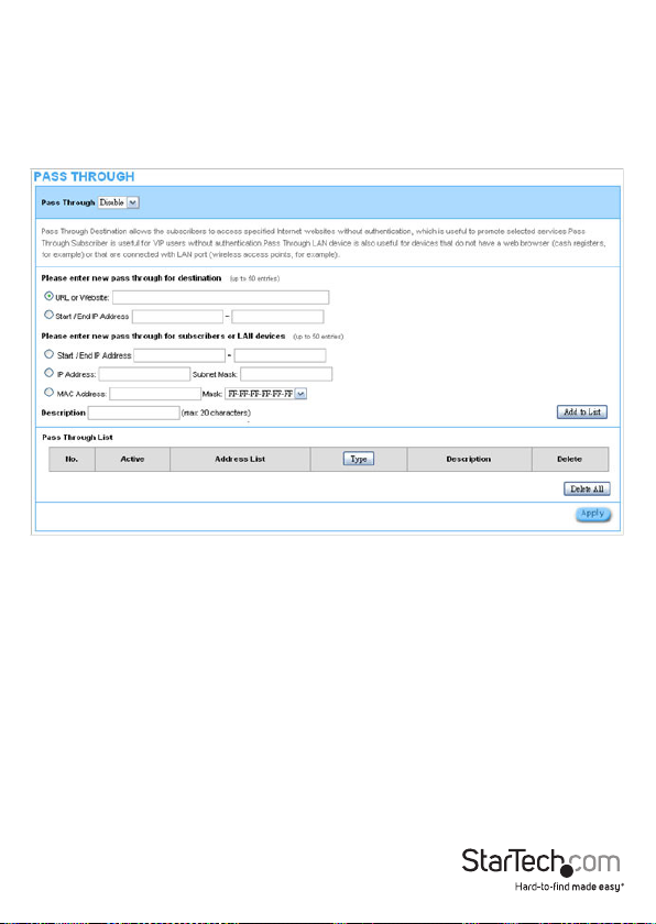
Pass Through
The Pass Through function allows you to specify devices that can pass through the AP,
without being checked and authorized.
Click the Add to List button once you’ve created a new entry.
Instruction Manual
17
Page 23

Item Default Description
Pass Through Disable Enables or disables the pass through function.
Destination URL/IP Address Pass Through
URL or Website Empty
Start / End IP
Address
Empty Enter the range of IP address you want to allow.
Enter the URL Page
(e.g. http://www.yahoo.com – Max 50 characters).
Subscriber IP/MAC Address or LAN Device Pass Through
Start / End IP
Address
IP Address
(single)
Empty Enter the range of IP address you want to allow.
Empty Enter the IP address you want to allow.
Subnet Mask Empty Enter the subnet mask.
MAC Address Empty Enter the MAC address you want to allow.
Mask Empty Enter the subnet mask.
Pass Through List
No. - The index number of pass through address.
Active Disable
Click the check box to activate or deactivate the
pass through address.
Address List - Displays the pass through address(s).
Type - Displays the type of pass through address.
Delete -
Select the check boxes and click ‘Delete’ to delete
the pass through address(s).
Click the Delete All button to clear the list of all entries.
Filtering
The Filtering function allows you to maintain a list of restricted destinations, which can
be used to block access to specied Internet sites or intranet areas globally (applies to
Guest and Employee networks).
Instruction Manual
18
Page 24
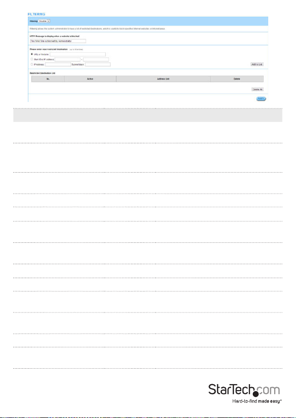
Item Default Description
Filtering Disable
HTTP Message to display
when a website is blocked
This Web Site
is blocked by
Administrator
Start / End IP Address Empty
Enables or disables the pass through
function.
Enter the message you would like to
display to the user when they attempt
to access a restricted area.
Enter the range of IP addresses you
want to allow.
Please enter new restricted destination
URL or Website Empty Enter the URL you would like to restrict.
Start / End IP Address Empty
IP Address (single) Empty
Enter a range of IP addresses you want
to restrict.
Enter the IP address you want to
restrict.
Subnet Mask Empty Enter the subnet mask.
Restricted Destination List
No. -
Active Disable
The index number of ltered
destinations.
Click the check box to activate or
deactivate the ltered address.
Address List - Displays the ltered address(es).
Delete -
Select the check boxes and click ‘Delete’
to delete the pass through address(es).
Click the Delete All button to clear the list of all entries.
Instruction Manual
19
Page 25

Secure Remote
The Secure Remote feature allows you to create a secure connection to a remote site or
back-end system through a VPN PPTP Client. If “Secure Remote” is enabled, the RADIUS
packet / syslog will be transferred to this secure connection.
Item Default Description
Auto-connect at Start-up
(Always connect)
PPTP Server IP address Empty
Username Empty
Password Empty
VPN Tunnel Displays the status.
Client IP Displays the IP address.
Disable
Click the Refresh button to update the connection status.
Click the check box to automatically
establish the PPTP connection.
Enter the PPTP server IP address
provided by your ISP.
Enter the username provided by your
ISP. The user name can consist of up
to 80 alphanumeric characters and is
case-sensitive.
Enter the user password provided
by your ISP (Max 80 case-sensitive
alphanumeric characters).
Click the button to Start / Stop the PPTP
connection.
Instruction Manual
20
Page 26
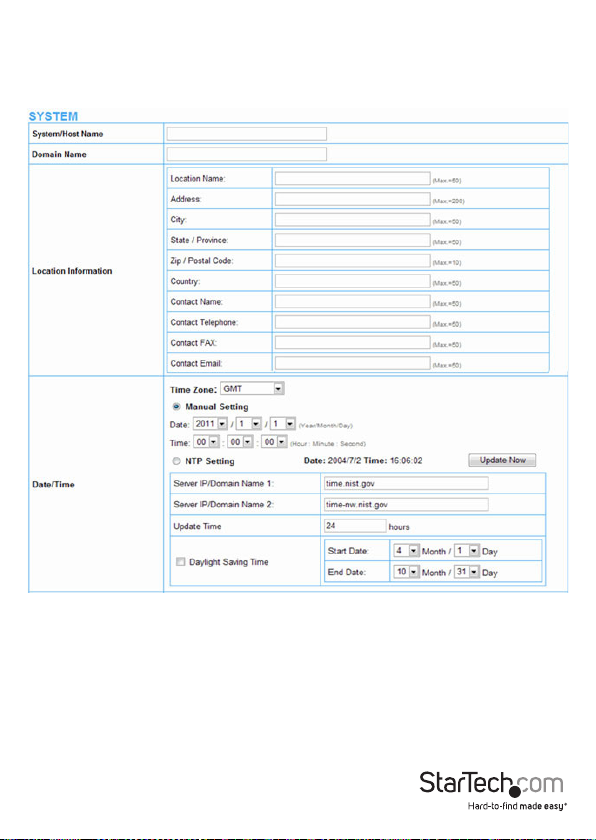
System
System
The System menu denes basic system settings.
Instruction Manual
21
Page 27

Item Default Description
System/Host Name Empty
Enter a system name (Max 40 alphanumeric
characters).
Domain Name Empty Enter a domain name (Max 80 1 characters).
Location Information Empty
Enter your location and contact information
if desired.
Date/Time
Time Zone GMT
Select the appropriate time zone for your
location.
Instruction Manual
22
Page 28

Manual Setting
Date (Year/Month/Day) -
Time
(Hour:Minute:Second)
- Set the system time.
NTP Setting
Server IP / Domain Name 1 Empty
Server IP / Domain Name 2 Empty
Update Time
24
Hours
Disable
Daylight Saving Time
Month/
Day
NAT (Network Address
Translation)
IP Plug and Play (iPnP
Technology)
Session Limit
Enable
Enable
Enable,
100
Layer 2 Isolation Security Enable
Guest Intranet Filtering Disable
Secure administrator IP
Addresses
Any
Manually set the date for the system
(Ranges from 2011 to 2035).
Enter the primary IP address or domain
name of NTP server (Max100 characters).
Enter the secondary IP address or domain
name of NTP server (Max100 characters).
Enter the frequency (hours) in which to
update the time.
Enables or disables Daylight Saving Time
(DST).
Set the Daylight Saving Time (DST) start and
end times.
Enables or disables the Network Address
Translation function
Enables or disables plug & play function.
When enabled, the user needn’t change
their network conguration to access the
Internet.
Limits the number of sessions allowed per
user at one time, when enabled.
If IP Plug and Play is enabled, you can enable
the Layer 2 Isolation Security function. When
Layer 2 Isolation Security is enabled, users
connected to the AP cannot communicate
with each other.
When enabled, you can specify up to 10 IP
addresses or ranges that Guest users cannot
visit.
Specify up to 5 IP addresses or ranges to
allow remote administrative access from
only those specied
Instruction Manual
23
Page 29

This function allows remote users to ping
Allow remote user to ping
the device
Enable
the AP. Ping is normally used to test the
physical connection between two devices,
to ensure that everything is working
correctly.
SSL Certicate Default Options: Default or Customer Certicate
WAN/LAN
The WAN / LAN menu allows you to congure IP addressing and WAN connection
settings.
Instruction Manual
24
Page 30

Item Default Description
Guest WLAN IP Address Setting
IP Address 10.59.1.200
Subnet Mask 255.255.255.0
Enter the internal LAN IP address for the
device.
Enter the subnet mask for the IP address
entered above.
Employee WLAN IP Address Setting
IP Address
Subnet Mask
10.59.2.200
255.255.255.0
The internal LAN IP address of your Wireless
Subscriber Server Gateway.
Enter the subnet mask for the IP address.
Guest LAN:
Congures the LAN ports to allow access to
the Internet with authentication required
LAN
Guest
(Guest ID / Key).
Employee LAN:
Congures the LAN ports to allow access to
the Internet without authentication.
WAN MAC Address
Default
The default MAC address is set to the WAN
physical interface on the device.
DHCP Client: Allows the device to obtain the
IP address and other TCP/IP settings from
your ISP.
Static IP: Allows you to specify the IP address
information for the WAN port.
WAN Port Mode
DHCP Client
PPPoE: Allows you to enter a username /
password and connection information for
your WAN connection (typically for North
American ADSL connections).
PPTP: Allows you to enter a username /
password and connection information for
your WAN connection (typically for European
ADSL connections).
Instruction Manual
25
Page 31

Server
The Server menu allows you to congure Web and DHCP server settings.
Item Default Description
Web Server
Enter the HTTP port number (80 or from 8010
HTTP Port 80
HTTPS Port 443
to 8060). For access to the AP under NAT, enter
using the format: “http://[IP Address]:[Port
Number]”
Enter the HTTPS port number (443 or from
4430 to 4440). For access to the AP under
NAT, enter using the format: “http://[IP
Address]:[Port Number]”
Instruction Manual
26
Page 32

Enter an idle timeout duration in minutes
Administrator
Idle-Timeout
5 Minutes
(From 1-1440). If the idle time out is set as 5
minutes, it means that if the administrator
doesn’t send packet in 5 minutes, the
administrator will be logged out.
DHCP Server
DHCP Server
DHCP
Server
DHCP Disable: Disable the DHCP server
function.
DHCP Server: Enable DHCP server function.
Guest DHCP
DHCP Pool Starting
Address
10.59.1.2
Enter the Starting IP address for the Guest
address pool.
Pool Size 253 Enter a DHCP pool size range (From 1 to 253).
Lease Time
300
Minutes
Enter a lease time value in minutes (From 1 to
71582788).
Primary DNS Server 168.95.1.1 Enter the IP address of the primary DNS server.
Secondary DNS
Server
Empty
Enter the IP address of the secondary DNS
server.
Employee DHCP
DHCP Pool Starting
Address
10.59.2.2
Enter the Starting IP address for the Employee
address pool.
Pool Size 253 Enter a DHCP pool size range (From 1 to 253).
Lease Time
300
Minutes
Enter a lease time value in minutes (From 1 to
71582788).
Primary DNS Server 168.95.1.1 Enter the IP address of the primary DNS server.
Secondary DNS
Server
Empty
Enter the IP address of the secondary DNS
server.
Instruction Manual
27
Page 33
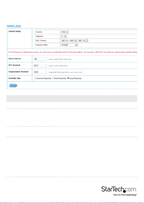
Wireless
The Wireless menu allows you to congure your desired wireless mode and applicable
settings.
Item Default Description
General Settings
Select the Country code:
Country FCC
-ESTI (Europe; Channel 1~13)
-FCC (North America; Channel 1~11)
Channel 6
Select the channel ID for wireless
connection.
Select one of the following modes:
-802.11n+802.11g+802.11b
-802.11n+802.11g
802.11 mode
-802.11g+802.11n
-802.11n only
-802.11g only
-802.11b only
Instruction Manual
28
Page 34

Channel Width
Auto
20/40MHz
Beacon Interval 200
RTS Threshold 2347
Fragmentation
Threshold
Preamble Type
2432
Long
Preamble
Indicates the frequency interval of the
beacon (From 1 to 1000).
This valid range is from 256-2342. This
setting determines the packet size at which
the AP issues a Request To Send (RTS) before
sending the packet. A low RTS Threshold
setting can be useful in areas where many
client devices are associating with the AP, or
in areas where clients are far apart and can
detect only the AP (not each other).
This setting determines the size at which
packets are fragmented. Enter a setting
ranging from 256 to 2432 bytes. Use a low
setting in areas where communication is
poor or where there is a great deal of radio
interference.
The preamble type is a section of data at the
head of a packet that contains information
the AP and client devices need when
sending and receiving packets. Select from
Long, Short or Dynamic preamble types.
Instruction Manual
29
Page 35
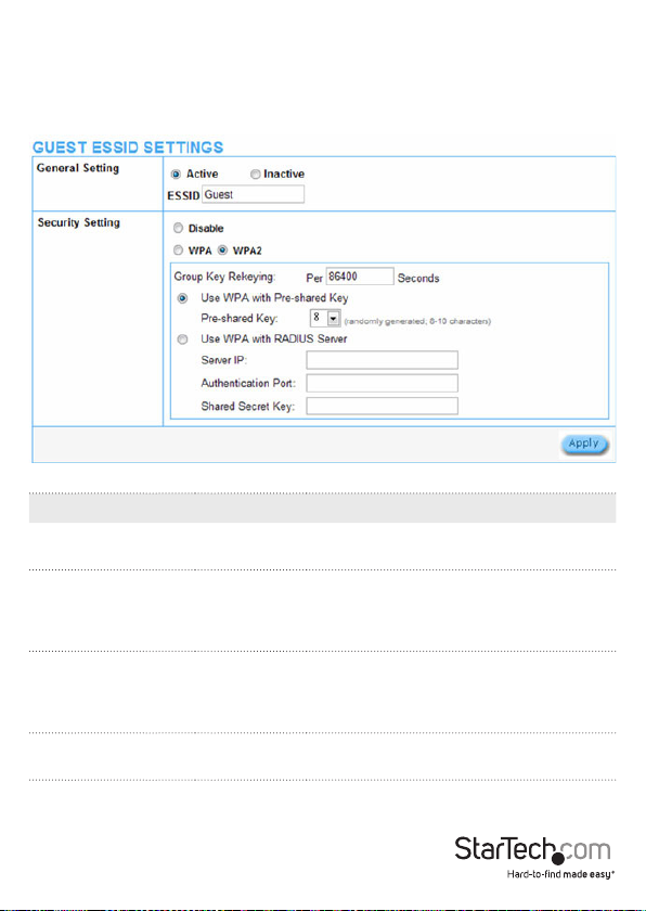
Guest Setting
Guest ESSID Settings
The Guest ESSID Settings menu allows you to congure your guest wireless settings
and security.
Item Default Description
General Settings Active
ESSID Guest
Security Enable
Group Key Re-Keying
86400
Seconds
Activate or de-activate the Guest wireless
connection interface.
The ESSID is the unique name that is
shared among all points in a wireless
network. It is case sensitive and must not
exceed 32 characters.
Disable to allow users to communicate
with the device without any data
encryption. Enable to use WPA or WPA2
data encryption.
Enter a number in seconds to set the force
re-keying interval.
Instruction Manual
30
Page 36

Pre-shared Key Empty
The AP will randomly generate keys at the
length specied here. (8-10 characters)
Use WPA with RADIUS Disable
Server IP Empty
Authentication Port 1812
Enter the RADIUS server IP address or
domain name (Max 15 characters).
Enter the authentication port number
(From 0 to 65535).
Shared Secret Key Empty Enter the RADIUS key
Authentication
The Authentication menu allows you to congure the type of guest user
authentication required.
Instruction Manual
31
Page 37

Item Default Description
No Authentication:
Subscriber can direct access the Internet
without enter username and password.
Built-in Authentication:
The AP provides “Built-in Authentication”
that allows you to build up an Internet
service without extra authentication
Authentication
Type
Built-in
Authentication
software. When selected, you can generate
the subscriber account inside the AP, and
the system will authenticate the subscriber
login according to the generated account.
User Agreement:
Subscriber must accept the service usage
agreement before they can access the
Internet. The Standard User Agreement
page can be congured in the Guest
Settings > Customization section
Enter the URL where your agreement
page is located or click the button to
Redirect URL Link Empty
create your own (sample code below). The
maximum character length of the URL Link
is 200.
The system automatically backs up
Current User
Information Backup
1 Min(s)
account information and unused
account to ash ROM. This function allow
administrator to adjust the backup interval
in minutes (From 1 to 1440).
SSL Login Page Disable
Enables or disables SSL security of login
page.
Instruction Manual
32
Page 38

Usage Time
The Usage Time menu allows you to manage account expiration and usage duration
settings.
Item Default Description
Expiration 12 hours
Usage Time 3 hours
Enter the number of hours/days that unused accounts
should be deleted after (Max 30 Hours / Days).
Enter the number of hours/days the guest account
should remain valid for (Max 30 Hours / Days).
PIN Length 4 The eld range is 4-6 characters.
Instruction Manual
33
Page 39

Customization
The Customization menu allows you to create a custom login page, add a logo, create
an information pop-up window and user agreement as needed.
Login Page Tab
Provides several dierent options for you to create or redirect guest users to your
login page.
Standard
Instruction Manual
34
Page 40
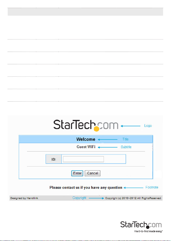
Item Default Description
Select the check box to display the logo le specied
Logo Disable
on the Logo tab.
Note: You will receive an error message if no logo has
been specied.
Title Welcome
Subtitle
Guest
Wi
Footnote Diable
Copywrite Enable
Background
Colour
FFFFFF Enter your desired background color in Hexadecimal.
Enter a page title for the top of the login box (Max 80
characters).
Enter the subtitle name of subscriber login page (Max
80 characters).
Enter a footnote if desired e.g. “Please contact Customer
Service, EXT 1000 for assistance” (Max 240 characters).
Enter a copyright note for the bottom of the login page
(Max 80 characters).
• Sample Standard Page
Instruction Manual
35
Page 41

Redirect
Item Default Description
Enter the URL where your login page is located (Max
Redirect Disable
200 characters), or click the button to create your own
(sample code below).
Instruction Manual
36
Page 42

Advanced
Item Default Description
Welcome
Slogan
Page
Background
Article Empty
Article Text
Colour
Article
Background
Color
Information Empty
Welcome Enter a Welcome slogan (Max 80 characters).
None
Enter your desired page background color in
Hexadecimal.
Enter a paragraph for advisement or announcements
(Max 1024 characters).
000000 Enter your desired text color in Hexadecimal.
None
Enter your desired article background color in
Hexadecimal.
Enter desired information such as address, telephone
number and fax (Max 80 characters).
Enter a footnote comment if desired e.g. “Please contact
Coments Empty
Customer Service, EXT 1000 for assistance” (Max 240
characters).
Frame
Item Default Description
Top Frame
URL Link
Bottom
Frame
Empty
_ This frame will show the standard login page.
Enter the URL where your top frame content is located
(Max 200 characters).
Instruction Manual
37
Page 43

• Sample Framed Page
Logo Tab
The Logo tab allows you to upload your company logo for use on the login page.
Item Default Description
File Path Empty Click Choose File to select a le from your local PC
Instruction Manual
38
Page 44

Information Window Tab
The Information Window tab allows you to create a customized message to new guests
after they log in.
Item Default Description
Display
Information
Window after a
subscriber logs
in successfully
Window Name
Main Message
Message
Description
Time Count
Label
Enabled – Pop Up
Information
Window
You can access the
Internet now!
This is an
information...
Remaining Usage
Redirect: Displays the Information Window
in the same tab that the user logs in from.
Pop Up: Shows a pop up message when
the user logs in.
Enter the window name to be shown in the
title bar (Max 30 characters).
Enter your main message / heading
(Max 30 characters).
Enter your desired message text to display
(Max 150 characters).
Enter your desired label for the usage
counter (Max 30 characters).
Enter notice text as desired, which will
Notice Message Disabled
appear at the bottom of the Information
Window in red (Max 150 characters per
level 1-3).
Instruction Manual
39
Page 45
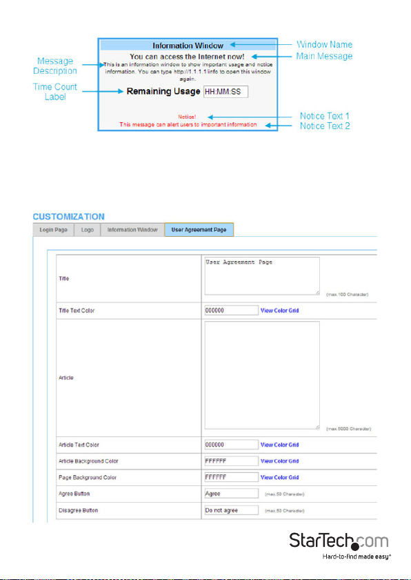
• Sample Information Window
User Agreement Tab
The User Agreement tab allows you to create a customized user agreement page for
guest users.
Note: The User Agreement screen can be enabled under Guest Settings >
Authentication
Instruction Manual
40
Page 46

Item Default Description
Title
Agreement
Page
Title Text Colour 000000
User
Enter the window name to be shown in the
title bar (Max 100 characters).
Enter your desired title text color in
Hexadecimal.
The article is allowed the administrator to
Article Empty
input a paragraph in the subscriber login
page for advisement or announcement (Max
1024 characters).
Article Text Colour 000000 Enter your desired text color in Hexadecimal.
Article Background
Color
Page Background
Color
FFFFFF
FFFFFF
Agree Button Agree
Disagree Button Disagree
Enter your desired article background color
in Hexadecimal.
Enter your desired page background color in
Hexadecimal.
Enter the button text for the agree button
(Max 50 characters).
Enter the button text for the disagree button
(Max 50 characters).
Instruction Manual
41
Page 47
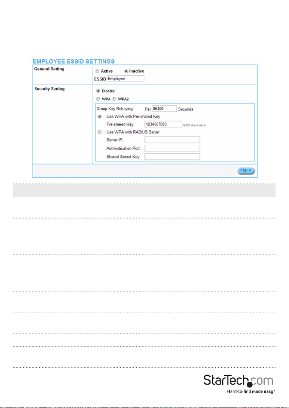
Employee Setting
Employee ESSID Settings
The Employee ESSID Settings menu allows you to congure your employee wireless
settings and security.
Item Default Description
General Settings Active
ESSID Employee
Security Enable
Group Key Re-Keying
Pre-shared Key Empty
Use WPA with RADIUS Disable
Server IP Empty
86400
Seconds
Activate or de-activate the wireless
connection interface.
The ESSID is the unique name that is shared
among all points in a wireless network. It
is case sensitive and must not exceed 32
characters.
Select disable to allow users to communicate
with the device without any data encryption.
Select enable to use WPA or WPA2 data
encryption.
Enter a number in seconds to set the force
re-keying interval.
The AP will randomly generate keys at the
length specied here. (8-10 characters)
Enter the RADIUS server IP address or domain
name (Max 15 characters).
Instruction Manual
42
Page 48
Authentication Port 1812
Shared Secret Key Empty Enter the RADIUS key
Enter the authentication port number from
0 to 65535.
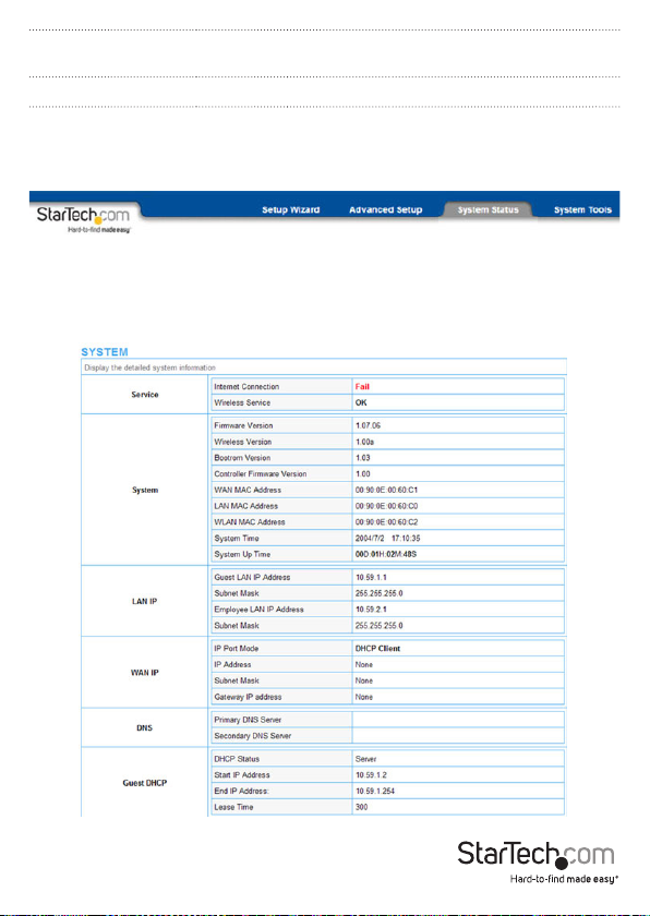
System Status Menu
System Report
The System report displays current basic system information, including: service
connection status, host name, LAN, WAN, DHCP Conguration, DNS, SSL Certicate,
network trac Information and the system rmware version number.
Instruction Manual
43
Page 49
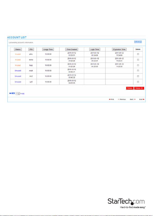
Account List
The Account List displays all account information on this device, including: the status,
PIN, usage time, time created, login time, expiration time and status.
This page will refresh automatically every 5 minutes, or you can click the Refresh
button in the top right corner to update manually.
• Click the Delete button to delete checked accounts
• Click Delete All to clear the list
• Click the column headings to change the sorting
Instruction Manual
44
Page 50

Account Log
The Account Log displays account activity information.
• Click the Export button to export the contents of the log to a text le (lename:
export.log)
• Click Clear Log to empty the log contents
• Click the column headings to change the sorting
Instruction Manual
45
Page 51
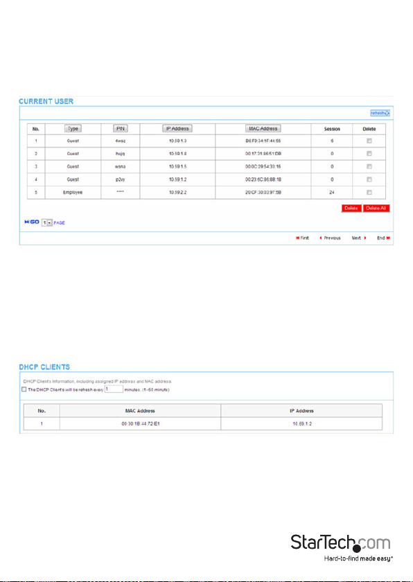
Current User Report
The Current User report displays currently logged-in user status and allows the
administrator to disconnect users if needed.
This page will refresh automatically every 5 minutes, or you can click the Refresh
button in the top right corner to update manually.
• Click Delete to disconnect the checked users
• Click Delete All to disconnect all current users
• Click the column headings to change the sorting
DHCP Clients Report
The DHCP Clients report displays the current DHCP addressing table.
Instruction Manual
46
Page 52
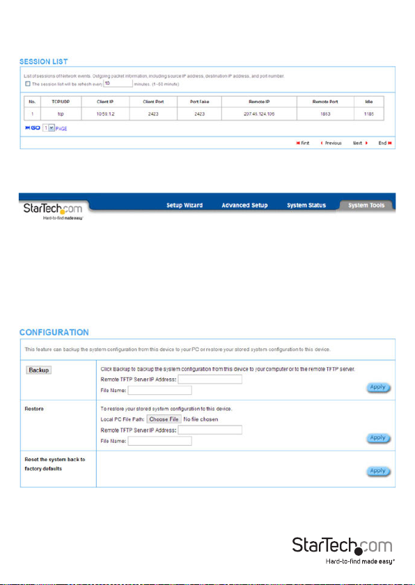
Session List
The Session List displays the real-time session usage information for the AP.
System Tools Menu
The System Tools Menu allows you to upgrade Firmware, change passwords and
backup or restore conguration les.
Conguration
The Conguration menu allows you to backup or restore the conguration settings for
the device.
Instruction Manual
47
Page 53

Item Default Description
Backup -
Remote TFTP Server IP
Address
File Name Empty Enter your desired le name.
Restore
Local PC File Path Empty
Remote TFTP Server IP
Address
File Name Empty Enter the le name in the File Name eld.
Reset the system back
to factory defaults
Empty Enter the IP address of the TFTP Server.
Empty Enter the IP address of TFTP Server.
-
Click the button to save the system
conguration to a le computer. (export.cfg)
Click Choose File to select a le from your
local PC
Click Apply and conrm to erase all
conguration settings and revert back to
factory default.
Firmware Upgrade
The Firmware Upgrade menu lets you upload a new rmware le manually or as a
scheduled task.
Note: Do not power o the device during the rmware upgrade process to avoid
damage to the unit.
Manual Firmware Upgrade Tab
The Manual Firmware Upgrade tab allows you to specify a local le or a TFTP address to
update the rmware.
Instruction Manual
48
Page 54

Item Default Description
Local PC File Path -
Click Choose File to select a le from
your local PC
Remote TFTP Server IP Address Empty Enter the IP address of TFTP Server.
File Name Empty
Control board rmware -
Enter the le name in the File
Name eld.
Click Choose File to select a le from
your local PC
Instruction Manual
49
Page 55

Scheduled Firmware Upgrade Tab
The Scheduled Firmware Upgrade tab allows you to specify a le location and
frequency for automated rmware upgrades.
Item Default Description
Disable/Enable Disable
Disables or enables the scheduled rmware
upgrade function.
TFTP Server IP Empty Enter the IP address of the TFTP Server.
File Synchronization Empty
View Sample File -
Enter the le name and location in the File
Synchronization eld.
Click the button to display synchronization le
example.
Frequency Weekly Set the rmware upgrade frequency.
Instruction Manual
50
Page 56

Boot Code
The Boot Code menu allows you to upload a new boot code le should an update
become available.
System Account
The System Account menu allows you to change the administration account for the
device.
Item Description
Username Enter a username up to 20, case-sensitive alphanumeric characters.
Password Enter a password up to 20, case-sensitive alphanumeric characters.
Conrm Re-enter the same password to conrm.
Instruction Manual
51
Page 57

SSL Certicate
The SSL Certicate menu allows you to add your certicate les to the device.
PING
The PING menu will issue the ping command to your specied IP address or URL.
Item Description
IP or URL Enter the IP address or the URL link.
Instruction Manual
52
Page 58

Restart
The Restart menu will reboot the device.
Logout
The Logout menu will exit from the conguration screen.
Instruction Manual
53
Page 59

Specications
Supported Wireless Standards IEEE802.11b/g/n
Chipset Ralink – RT3052
Connectors 5 x RJ45 Ethernet Female
Antenna Conguration 2x2:2 (TxR:s)
Wireless Frequency Range 2.400 – 2.484
Wireless Bandwidth 20/40MHz
WPA(TKIP with IEEE 802.1x)
Wireless Encryption Supported
Maximum Wireless Distance 30m
Maximum Data Transfer Rate
Enclosure Material Plastic
Operating Temperature 0°C to 50°C (32°F to 122°F)
Storage Temperature -10°C to 60°C (14°F to 140°F)
Humidity 20~90% Non-Condensing
Dimensions 223 x 143 x 36 mm
WPA2(AES with IEEE 802.1x)
WPA -PSK
300Mbps (Wireless-N)
10/100 Mbps (RJ45 Ethernet)
Instruction Manual
54
Page 60

Technical Support
StarTech.com’s lifetime technical support is an integral part of our commitment to
provide industry-leading solutions. If you ever need help with your product, visit
www.startech.com/support and access our comprehensive selection of online tools,
documentation, and downloads.
For the latest drivers/software, please visit www.startech.com/downloads
Warranty Information
This product is backed by a two year warranty.
In addition, StarTech.com warrants its products against defects in materials
and workmanship for the periods noted, following the initial date of purchase.
During this period, the products may be returned for repair, or replacement with
equivalent products at our discretion. The warranty covers parts and labor costs only.
StarTech.com does not warrant its products from defects or damages arising from
misuse, abuse, alteration, or normal wear and tear.
Limitation of Liability
In no event shall the liability of StarTech.com Ltd. and StarTech.com USA LLP (or their
ocers, directors, employees or agents) for any damages (whether direct or indirect,
special, punitive, incidental, consequential, or otherwise), loss of prots, loss of business,
or any pecuniary loss, arising out of or related to the use of the product exceed the
actual price paid for the product. Some states do not allow the exclusion or limitation
of incidental or consequential damages. If such laws apply, the limitations or exclusions
contained in this statement may not apply to you.
Instruction Manual
55
Page 61

Hard-to-nd made easy. At StarTech.com, that isn’t a slogan. It’s a promise.
StarTech.com is your one-stop source for every connectivity part you need. From
the latest technology to legacy products — and all the parts that bridge the old and
new — we can help you nd the parts that connect your solutions.
We make it easy to locate the parts, and we quickly deliver them wherever they need
to go. Just talk to one of our tech advisors or visit our website. You’ll be connected to
the products you need in no time.
Visit www.startech.com for complete information on all StarTech.com products and
to access exclusive resources and time-saving tools.
StarTech.com is an ISO 9001 Registered manufacturer of connectivity and technology
parts. StarTech.com was founded in 1985 and has operations in the United States,
Canada, the United Kingdom and Taiwan servicing a worldwide market.
 Loading...