

Page 1

Enhanced Console Server
ECS0016
Page 2

FCC Compliance Statement
This equipment has been tested and found to comply with the limits for a Class B digital device, pursuant to part 15 of the FCC Rules. These limits are designed to provide reasonable
protection against har mful interference in a residential installation. This equipment generates,
uses and can radiate radio frequency energy and, if not installed and used in accordance with
the instructions, may cause harmful interference to radio communications. However, there is
no guarantee that interference will not occur in a particular installation. If this equipment does
cause harmful interference to radio or television reception, which can be determined by turning
the equipment off and on, the user is encouraged to try to correct the interference by one or
more of the following measures:
Reorient or relocate the receiving antenna.•
Increase the separation between the equipment and receiver.•
Connect the equipment into an outlet on a circuit different from that to which the receiver •
is connected.
Consult the dealer or an experienced radio/TV technician for help.•
Use of Trademarks, Registered Trademarks, and other Protected Names and Symbols
This manual may make reference to trademarks, registered trademarks, and other protected
names and/or symbols of third-party companies not related in any way to StarTech.com. Where
they occur these references are for illustrative purposes only and do not represent an endorsement of a product or service by StarTech.com, or an endorsement of the product(s) to which
this manual applies by the third-party company in question. Regardless of any direct acknowledgement elsewhere in the body of this document, StarTech.com hereby acknowledges that all
trademarks, registered trademarks, service marks, and other protected names and/or symbols
contained in this manual and related documents are the property of their respective holders.
Page 3

Instruction Manual
Instruction Manual
Table of Contents
Introduction .................................................................................... 1
Features ......................................................................................1
Package Contents .......................................................................1
Initial Configuration ....................................................................... 2
Power Connection .......................................................................2
Management Console Connection ............................................... 3
ARPPing IP Address Assignment................................................4
Administrator Password ............................................................... 6
Network IP address .....................................................................7
System Services ..........................................................................8
HTTPS .........................................................................................9
HTTP ...........................................................................................9
Telnet ........................................................................................... 9
SSH .............................................................................................9
SNMP ..........................................................................................10
Ping .............................................................................................10
Base ............................................................................................10
Communications Software ...........................................................11
MetaConnect ...............................................................................11
Applications & Database Servers ................................................11
Web Server ..................................................................................11
Desktop PCs................................................................................11
Network Appliance ......................................................................11
PuTTY .........................................................................................12
SSHTerm .....................................................................................13
i
Page 4

Instruction Manual
Serial Port and Network Host Configuration............................... 13
Configuring Serial Ports ..............................................................13
Common Settings ........................................................................15
Console Server Mode ..................................................................16
SDT Mode ...................................................................................20
Power Strip Mode ........................................................................20
Terminal Server Mode ................................................................. 20
Serial Bridging Mode ...................................................................21
Syslog ..........................................................................................21
Add / Edit Users...........................................................................22
Authentication ..............................................................................24
Network Hosts .............................................................................25
Serial Port Cascading ..................................................................27
Remote Power Control (RPC) .................................................... 32
Uninterruptible Power Supply Control (UPS) ...............................36
Overview of Network UPS Tools (NUT) ......................................43
Environmental Monitoring ............................................................45
Failover and Out-of-Band Dial Access ........................................ 50
OoB Dial-In access ......................................................................50
Configure Dial In PPP..................................................................51
Using The MetaConnect client ....................................................53
Set up Windows XP/ 2003 client..................................................53
Set up earlier Windows clients ....................................................53
Set up Linux clients .....................................................................54
Secure Tunneling & MetaConnect ................................................ 56
Telnet or SSH connection to serially attached devices ................56
MetaConnect for OoB Connection to the Gateway ......................58
MetaConnect Public Key Authentication .....................................60
ii
Page 5

Instruction Manual
Setting up MetaConnect for Remote Desktop access ................61
Set up MetaConnect Serial Ports on ECS0016 ..........................62
SSH port forward over the ECS0016 Serial Port .........................63
Alerts and Logging ........................................................................ 64
Enable SMTP, SNMP and/or Nagios ...........................................64
Configure Alerts ...........................................................................65
Remote Log Storage ...................................................................67
Power Control ................................................................................ 68
Configuring Serial Port Power Strips ...........................................70
Configuring IPMI Power Management .........................................70
Configuring Browser Controlled Power Strips ............................. 71
Nagios Integration ......................................................................... 72
Nagios overview ..........................................................................72
Central management and setting up MetaConnect for Nagios ....73
Central Site ..................................................................................75
NagiosServer ...............................................................................75
Network .......................................................................................75
ECS0016 .....................................................................................75
Remote Site .................................................................................75
Serial ...........................................................................................75
Managed Hosts ...........................................................................75
Remote ECS0016 Gateway .........................................................78
System Management ..................................................................... 82
System Administration and Reset ...............................................82
Firmware Upgrades .....................................................................83
Configure Date and Time ............................................................84
iii
Page 6

Instruction Manual
Status Reports ............................................................................... 85
Port Access and Active Users ..................................................... 85
Statistics ......................................................................................86
Support Reports ..........................................................................86
Syslog ..........................................................................................86
Device Management ....................................................................88
Port Log Management .................................................................88
Power Management ...................................................................88
Serial Port Terminal Connection .................................................. 89
Basic Configuration - Linux Commands ..................................... 90
The Linux Command line .............................................................91
Administration Configuration .......................................................93
Date and Time Configuration .......................................................94
Network Configuration .................................................................95
Serial Port Configuration .............................................................99
Users ...........................................................................................100
Trusted Networks .........................................................................101
Event Logging Configuration .......................................................102
MetaConnect Host Configuration ................................................104
Advanced Configuration ............................................................... 105
Advanced Portmanager ...............................................................105
pmshell ........................................................................................105
pmchat .........................................................................................106
pmusers .......................................................................................106
Portmanager Daemon .................................................................107
Signals .........................................................................................108
External Scripts and Alerts ..........................................................108
iv
Page 7

Instruction Manual
Raw Access to Serial Ports ......................................................... 110
Access to Serial Ports .................................................................110
Accessing the Console Port ........................................................110
IP - Filtering .................................................................................111
Customizing the IP-Filter: ............................................................ 112
Modifying SNMP Configuration ...................................................113
Power Strip Control .....................................................................115
Glossary of Terms Used ..............................................................121
TERM ..........................................................................................121
MEANING ....................................................................................121
Technical Specifications ..............................................................129
Technical Support ......................................................................... 132
Warranty Information .................................................................... 132
v
Page 8

Instruction Manual
Introduction
Thank you for purchasing a StarTech.com Conyx ECS0016 Enhanced
Console Server. This innovative remote service management solution
enables system administrators and network managers to affordably monitor and control their computers, networks and connected serial devices
remotely, from anywhere in the world (using an Internet connection).
Features
DHCP client for dynamic IP assignment•
Offline data logging (Syslog, NFS, CIFS)•
Out-of-band access (external dial-up modem)•
Port triggers with SMNP and email alerts•
SSH tunneled serial bridging•
Strong Encryption (3DES, Blowfish, AES, Arcfour)•
SUN / Solaris ready•
Telnet/SSH/Raw TCP connect•
Unlimited user accounts•
Package Contents
1 x DCE Connector•
1 x DTE Connector•
1 x ECS0016 Enhanced Console Server•
1 x Power Cable•
1 x Software/User Manual CD•
1 x Quick Start Guide•
2 x CAT5 Cables•
2 x Mounting Brackets•
1
Page 9

Instruction Manual
Initial Conguration
Unpack the ECS0016 kit and verify you have all of the par ts indicated in
the Package Contents list shown on the previous page, and that they all
appear in good working order.
If you are installing your ECS0016 in a rack, you will need to attach the
rack-mounting brackets supplied with the unit, and install the unit in the
rack. Following this, proceed to connect your ECS0016 to the network, as
well as to the serial ports of the controlled devices, and to an power outlet
as outlined below.
Power Connection
The ECS0016 and CM4148 models have a built-in universal
autoswitching AC power supply. This power supply accepts AC input
voltage between 100 and 240 VAC with a frequency of 50 or 60 Hz and
the power consumption is less than 20W.
AC power socket
The ECS0016 has an IEC AC power socket located at the rear of the
metal case, which uses a conventional IEC AC power cord. The North
American power cord is provided by default.
There is a warning notice printed on the back of each unit:
2
Page 10

Instruction Manual
Management Console Connection
The ECS0016 is pre-configured with a default IP Address: 192.168.0.1
and Subnet Mask: 255.255.255.0 .
Directly connect a PC or workstation to the ECS0016. To configure the
ECS0016 with a browser, the connected PC or workstation should have
an IP address in the same range as the ECS0016 (e.g. 192.168.0.100)
Please note: For initial configuration, it is recommended that the
ECS0016 be connected directly to a single PC or workstation. If you
choose to connect your LAN before completing the initial setup steps:
Ensure there are • no other devices on the LAN with an IP Address of
192.168.0.1
Ensure the Console Server and the PC/workstation are on the • same
LAN segment, with no interposed router appliances
To configure the IP Address of your Linux or Unix PC/workstation simply
run ipconfig. For Windows PCs (Win9x/Me/2000/XP/ NT):
Click 1. Start > Settings, then select Control Panel and double-click
Network Connections (for 95/98/Me, double click Network).
Right-click on 2. Local Area Connection and select Properties.
Select 3. Internet Protocol (TCP/IP) and click Properties.
Select 4. Use the following IP address and enter the following details:
IP address: 192.168.0.100 Subnet mask: 255.255.255.0.
If you wish to retain your existing IP settings for this network connection,
click Advanced and add the above as a secondary IP connection.
3
Page 11

Instruction Manual
ARPPing IP Address Assignment
If it is not convenient to change the PC/workstation network address, you
can use the ARP-Ping command to reset the ECS0016 IP address. To do
this from a Windows PC:
Click 1. Start > Run
Type 2. cmd in the text box provided and click OK to open the command
line
Type 3. arp –d to flush the ARP cache:
Type 4. arp –a to view the current ARP cache which should now be
empty.
Now, add a static entry to the ARP table and ping the ECS0016 to
prompt it to assume the IP address.
The following example illustrates an ECS0016 with a MAC Address
00:13:C6:00:02:0F (designated on the label on the bottom of the unit),
and we are setting its IP address to 192.168.100.23. Also, the PC/work
station issuing the arp command must be on the same network
segment as the ECS0016 (i.e. have an IP address of 192.168.100.xxx).
Type 5. arp -s 192.168.100.23 00-13-C6-00-02-0F (Note for UNIX the
syntax is: arp -s 192.168.100.23 00:13:C6:00:02:0F)
Type 6. ping -t 192.18.100.23 to start a continuous ping to the new IP
Address.
Turn on the ECS0016 and wait for it to configure itself with the new IP 7.
Address. It will start replying to the ping at this point.
Type 8. arp –d to flush the ARP cache again.
Activate your preferred browser on the connected PC/ workstation and 9.
enter https://192.168.0.1 in the URL field.
4
Page 12

Instruction Manual
You will be prompted to log in. Enter the default administration username
and administration password:
Username: root Password: default
Please note: The ECS0016 is factory configured with HTTP disabled and
HTTPS enabled appliances
Please note: Note If you are not able to connect to the Management
Console at 192.168.0.1 or if the default Username / Password were not
accepted then reset your ECS0016
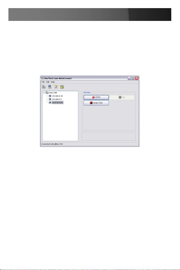
A Welcome screen will appear , listing the four basic installation configuration steps:
After completing each of the steps listed, you can return to the configuration list by clicking in the top left corner of the screen on the StarTech.com
logo.
As you complete each step, the configuration list will be updated (e.g.
after you have configured the serial ports it will display this step as Done.
5
Page 13
Instruction Manual
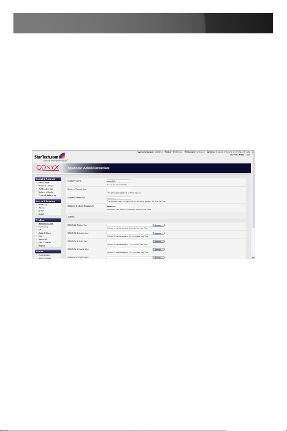
Administrator Password
For security reasons, only the Administrator (the administration user
named root) can initially log into your gateway; only those people who
know the root password can access and reconfigure the ECS0016 gateway itself.
As such, it is important that you enter and confirm a new password before
giving the ECS0016 any access to, or control of, your computers and
network appliances. To do so:
Select 1. System: Administration
Enter a new System Password then re-enter it in the field marked 2.
confirm System Password. This is the new password for root, the main
administrative user account, so it is important that you choose a
complex password, and keep it safe.
(Optional)At this stage you may also wish to enter a 3. System Name
and System Description for the ECS0016 gateway to give it a unique
ID and make it simple to identify.
Click 4. Apply. As you have changed the password you will be prompted
to log in again. This time use the new password.
6
Page 14
Instruction Manual
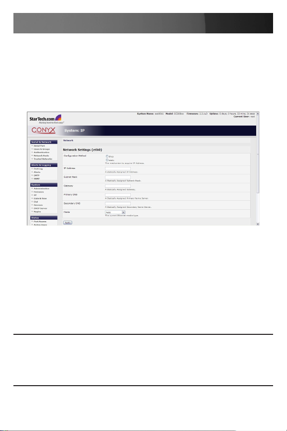
Network IP address
You now must enter an IP address for the principal Ethernet (LAN/Network/Network1) port on the ECS0016 gateway, or enable its DHCP client
so that it automatically obtains an IP address from a DHCP server on the
network to which it is connected.
On the System: IP menu:
Select the 1. Network page then check DHCP or Static for the
Configuration Method
If you selected 2. Static you must manually enter the new IP Address,
Subnet Mask, Gateway and DNS server details. This selection
automatically disables the DHCP client.
If you selected DHCP, the ECS0016 will look for configuration details 3.
from a DHCP server on your management LAN. This selection
automatically disables any static address. The ECS0016 MAC address
can be found on a label on the base plate of the unit.
Please note: In its factory default state (with no Configuration Method
selected) the ECS0016 has its DHCP client enabled, so it automatically
accepts any network IP address assigned by a DHCP server on your network. In this initial state, the ECS0016 will then respond to both its Static
address (192.168.0.1) and its newly assigned DHCP address.
7
Page 15
Instruction Manual
By default the ECS0016 LAN port auto detects the Ethernet connection
speed. However you can use the Media menu to lock the Ethernet to 10
Mb/s or 100Mb/s and to Full Duplex (FD) or Half Duplex (HD).
Please note: If you have changed the ECS0016 IP address, you may
need to reconfigure your PC/workstation so it has an IP address that is
in the same network range as this new address (as detailed in an earlier
note in this chapter).
Click 4. Apply. You will need to reconnect the browser on the PC /
workstation that is connected to the ECS0016, by entering http://new
IP address .
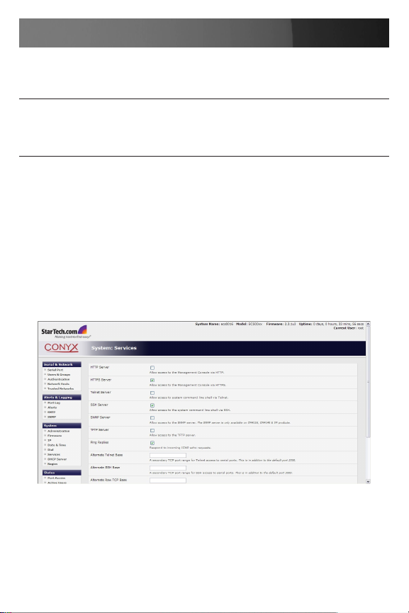
System Services
The Administrator can access and configure the ECS0016 gateway using
a range of access protocols. The factory default enables HTTPS and SSH
access and disables HTTP and Telnet. The Administrator can simply disable any of the services, or enable others.
Select the System: Services option then select /deselect for the service
to be enabled /disabled. The following access protocol options are available:
8
Page 16

Instruction Manual
HTTPS
This ensures secure browser access to all of the Management Console
menus. It also allows appropriately configured Users secure browser access to selected Management Console Manage menus.
If you enable HTTPS, the Administrator will be able to use a secure
browser connection to the ECS0016 gateway’s Management Console.
By default HTTPS is enabled, and it is recommended that only HTTPS
access be used if the gateway is to be managed over any public network
(e.g. the Internet).
HTTP
The HTTP service allows the Administrator basic browser access to
the Management Console. It is recommended that the HTTP service be
disabled if the ECS0016 gateway is to be remotely accessed over the
Internet.
Telnet
This gives the Administrator telnet access to the system command line
shell (Linux commands). While this may be suitable for a local direct
connection over a management LAN, it is recommended this service be
disabled if the ECS0016 is to be remotely administered.
SSH
This service provides secure SSH access to the Linux command line
shell. It is recommended you choose SSH as the protocol where the Administrator connects to the gateway over the Internet or any other public
network. This will provide authenticated communications between the
SSH client program on the remote PC/workstation and the SSH server in
the gateway.
9
Page 17

Instruction Manual
There are also a number of related service options that can be configured
at this stage:
SNMP
This will enable netsnmp in the gateway, which will keep a remote log of
all posted information. SNMP is disabled by default. To modify the default
SNMP settings, the Administrator must make the edits at the command
line.
Ping
This allows the ECS0016 to respond to incoming ICMP echo requests.
Ping is enabled by default, however for security reasons this service
should generally be disabled following initial configuration.
And there are some serial port access parameters that can be configured
on this menu:
Base
The ECS0016 uses specific default ranges for the TCP/IP ports for the
various access services that Users and Administrators can use to access
devices attached to serial ports. The Administrator can also set alternate
ranges for these services, and these secondary ports will then be used in
addition to the defaults.
The default TCP/IP base port address for telnet access is 2000, and the
range for telnet is IP Address: Port (2000 + serial port #) i.e. 2001 – 2048.
If the Administrator were to set 8000 as a secondary base for telnet,
serial port #2 on the gateway can be telnet accessed at IP Address:2002
and at IP Address:8002.
The default base for SSH is 3000; for Raw TCP is 4000; and for
RFC2217, 5000.
Once you’ve made the appropriate selections, click Apply.
10
Page 18
Instruction Manual
Communications Software
You have configured access protocols for the Administrator client to use
when connecting to the ECS0016. User clients (who you may set up later)
will also use these protocols when accessing ECS0016 serial attached
devices and network attached hosts.
You will need to have appropriate communications software tools set
up on the Administrator (and User) client’s PC/workstation. ECS0016
includes MetaConnect as the recommended client software tool, however
other generic tools such as PuTTY and SSHTerm may be used, and
these are all described below:
MetaConnect
StarTech.com recommends using the MetaConnect communications
software tool for all communications with ECS0016 gateways, to ensure
these communications are secure. Each ECS0016 is supplied with an
unlimited number of MetaConnect licenses to use with that gateway.
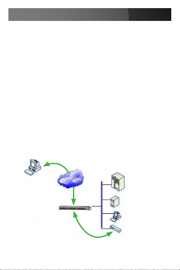
MetaConnect is a lightweight tool that enables Users and Administrators
to securely access the ECS0016 gateway, and the various computers,
network devices and appliances that may be serially or network connected to the gateway.
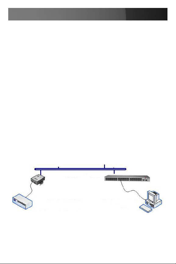
Applications &
MetaConnect
(RDP/VNC/Telnet/
HTTP Client)
SSH Encrypted
LAN
Tunnel
Database Servers
Web Server
RDP/VNC/Telnet/HTTP Sessions forwarded to devices/
service processors on the
LAN
Desktop PCs
Network Appliance
11
Page 19
Instruction Manual
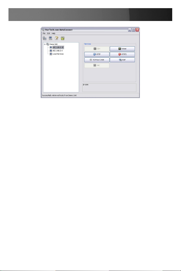
MetaConnect is a Java client program that couples the SSH tunneling
protocol with popular access tools such as Telnet, SSH, HTTP, HTTPS,
VNC, RDP, to provide point-and-click secure remote management access
to all the systems and devices being managed.
MetaConnect can be installed on Windows 2000, XP, 2003, Vista™ PCs
and on most Linux, UNIX and Solaris configurations
PuTTY
Communications packages like PuTTY can be also used to connect to the
ECS0016 gateway command line.
PuTTY is a freeware implementation of Telnet and SSH for Win32 and
UNIX platforms, that runs as an executable application without needing
to be installed onto your system. PuTTY (the Telnet and SSH client itself)
can be downloaded at http://www.tucows.com/preview/195286
To use PuTTY for an SSH terminal session from a Windows client, you •
enter the gateway’s IP address as the ‘Host Name (or IP address)
To access the ECS0016 command line you select ‘SSH’ as the •
protocol, and use the default IP Port 22
Click ‘Open’ and you will be presented with the ECS0016 login prompt. •
(You may also receive a ‘Security Alert’ that the host’s key is not
cached, you will need to choose ‘yes’ to continue.)
Using the • Telnet protocol is similarly simple but you use the default
port 23
12
Page 20

Instruction Manual
SSHTerm
Another common communications package that may be useful is SSHTerm, an open source package that can be downloaded from
http://sourceforge.net/projects/sshtools
To use SSHTerm for an SSH terminal session from a Windows Client, you
simply Select the File option and click on New Connection
A new dialog box will appear for your ‘Connection Profile’ where you can
type in the host name or IP address (for the ECS0016 unit) and the TCP
port that the SSH session will use (port 22). Then, enter your username
and choose password authentication and click Connect.
You may receive a message about the host key fingerprint, and you will
need to select ‘yes’ or ‘always’ to continue.
The next step is password authentication, where you will be prompted for
your username and password from the remote system.
You will then be logged on to the ECS0016 gateway.
Serial Port and Network Host Conguration
The ECS0016 enables access and control of serially and network
attached devices (hosts). The Administrator must configure the port
access privileges for each of these devices, and specify the selection of
services that can be used to control the devices. The Administrator must
also set up Users and specify each User’s individual access and control
privileges.
13
Page 21

Instruction Manual
Conguring Serial Ports
To configure the serial port, you must first set the protocols and the
RS232 parameters that are to be used for the data connection to that port
(e.g. baud rate).
Then you must select what mode the port is to operate in. Each port can
be set to support one of five operating modes:
I
Console Server mode enables remote network access to the
attached devices serial console port
I I
SDT mode enables graphical console (RDP, VNC, HTTPS etc)
access to hosts that are serially connected
I I I
Power Device mode sets up the serial port to communicate with an
intelligent serial controlled power strip
IV
Terminal Server mode sets the serial port to await an incoming
terminal login session
V
Serial Bridge mode enables the transparent interconnection of two
serial port devices over a network
You can also configure the ECS0016 to support the remote syslog protocol on a per serial port basis.
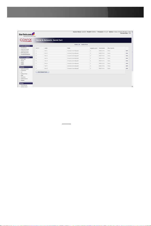
Select • Serial & Network: Serial Port and you will see the current
labels, modes, and RS232 protocol options that are currently set up for
each serial port
If you wish to set the same protocol options for multiple serial ports at •
once, click Edit Multiple Ports and select which ports you wish to
configure as a group
By default each serial port is set in • Console Server mode. For the por t
to be reconfigured, click Edit
14
Page 22
Instruction Manual
When you have reconfigured the common settings and the mode for •
each port, you set up any remote syslog, then click Apply
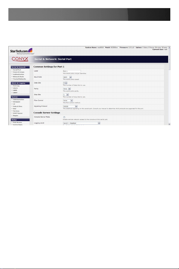
Common Settings
There are a number of common settings that can be set for each serial
port, that are independent of the mode in which the port is being used.
These serial port parameters must be set so they match the port parameters of the devices you attach to that port:
Specify a label for the port •
Select the appropriate Baud Rate, Parity, Data Bits, Stop Bits and •
Flow Control for each port. (Note that the RS485 field is not relevant for
ECS0016 gateways)
15
Page 23
Instruction Manual
Before proceeding with further serial port configuration, you should •
connect the ports to the serial devices they will be controlling, and
ensure they have matching settings
Please Note that the serial ports are all factory set to RS232 9600 baud,
no parity, 8 data bits, 1 stop bit and Console Server Mode.
The baud rate can be changed to 2400 – 230400 baud using the management console. Lower baud rates (50, 75, 110, 134, 150, 200, 300,
600, 1200, 1800 baud) can be configured from the command line.
Console Server Mode
Select Console Server Mode to enable remote management access to
the serial console that is attached to this serial port:
Logging Level - specifies the level of information to be logged and
monitored
Telnet - With the Telnet service enabled on the ECS0016, a Telnet
client on a User or Administrator’s PC/workstation can connect to a serial
device attached to this serial port on the gateway. The Telnet communications are unencrypted, so this protocol is generally recommended only for
local connections.
16
Page 24

Instruction Manual
From Win2000/XP/NT, you can run telnet from the command prompt •
(cmd.exe)
You can also use standard communications packages like PuTTY to •
set a direct Telnet (or SSH) connection to the serial ports (see box
below)
Also, if the remote communications are being tunneled with •
MetaConnect, then Telnet can be used for securely accessing
attached devices
In Console Server mode, Users and Administrators can use MetaConnect to set up secure Telnet connections that are SSH tunneled from
their client PC/workstations to the serial port on the ECS0016. MetaConnect then enables those secure Telnet connections to be selected with a
simple point and click.
To use MetaConnect to access consoles on the ECS0016 serial ports,
you must configure MetaConnect using the ECS0016 as a gateway, then
as a host, with Telnet service on Port (2000 + serial port #) i.e. 2001–
2016 enabled.
MetaConnect can be installed on Windows 2000, XP, 2003, Vista™ PCs
and on most Linux platforms. Solaris platforms are also supported, however they must have Firefox installed.
Enter the ECS0016 gateway’s IP address as the ‘Host Name (or IP address)’. Select ‘Telnet’ as the protocol and set the ‘TCP port’ to 2000 plus
the physical serial port number (i.e. 2001 to 2016).
Click the ‘Open’ button. You may then receive a ‘Security Alert’ that the
host’s key is not cached - choose ‘yes’ to proceed. You will then be presented with the login prompt of the remote system connected to the serial
port chosen on the ECS0016 device, where you can login as normal and
use the host serial console screen.
17
Page 25
Instruction Manual
SSH
It is recommended that you use SSH as the protocol whereby the User
or Administrator connects to the ECS0016 gateway (or connects to the
attached serial consoles) over the Internet (or any other public network).
This will provide authenticated SSH communications between the SSH
client program on the remote user’s PC/workstation and the gateway, so
the user’s communication with the serial device attached to the gateway
is secure.
For SSH access to the consoles on devices attached to the ECS0016
serial ports, you can use MetaConnect. You configure MetaConnect with
the ECS0016 as a gateway, then as a host, and you enable SSH service
on Port (3000 + serial port #) i.e. 3001-3016.
Also, you can use common communications packages, like PuTTY or
SSHTerm to SSH connect directly to por t address IP Address _ Port
(3000 + serial port #) i.e. 3001–3016
Alternately, SSH connections can be configured using the standard SSH
port 22. The serial port being accessed is then identified by appending a
descriptor to the username. This syntax supports any of:
<username>:<portXX>
<username>:<port label>
<username>:<ttySX>
<username>:<serial>
18
Page 26

Instruction Manual
For a User named ‘Paul’ to access serial port 2, when setting up the
SSHTerm or the PuTTY SSH client, instead of typing username = paul
and ssh port = 3002, the alternate is to type username = paul:port02 (or
username = fred:ttyS1) and ssh port = 22.
Or, by typing username=fred:serial and ssh port = 22, the User is presented with a port selection option:
This syntax enables Users to set up SSH tunnels to all serial ports with
only a single IP port 22 having to be opened in their firewall/gateway.
TCP
RAW TCP allows connections directly to a TCP socket. However while
communications programs like PuTTY also supports RAW TCP, this protocol would usually be used by a custom application
For RAW TCP, the default port address is IP Address _ Port (4000 + serial
port #) i.e. 4001 – 4016.
RAW TCP also enables the serial port to be tunneled to a remote
ECS0016 client gateway, so two serial port devices can be transparently
interconnect over a network.
RFC2217
Selecting RFC2217 enables serial port redirection on that port. For
RFC2217, the default port address is IP Address _ Port (5000 + serial
port #) i.e. 5001 – 5016.
Special client software is available for Windows UNIX and Linux that
supports RFC2217 virtual com por ts, so a remote host can monitor and
manage remote serially attached devices, as though they were connected
to the local serial port.
19
Page 27

Instruction Manual
RFC2217 also enables the serial port to be tunneled to a remote
ECS0016 client gateway, so two serial port devices can be transparently
interconnect over a network.
Accumulation Period
By default, once a connection has been established for a particular serial
port (such as a RFC2217 redirection or Telnet connection to a remote
computer) then any incoming characters on that port are forwarded over
the network on a character by character basis. The accumulation period
changes this by specifying a period of time that incoming characters will
be collected before then being sent as a packet over the network.
Escape Character (esc)
This enables you to change the character used for sending escape characters. The default is ~.
SDT Mode
This Secure Tunneling setting allows port forwarding of RDP, VNC, HTPP,
HTTPS, SSH, Telnet and other LAN protocols through to computers which
are locally connected to the ECS0016 by their serial COM port. However
such port forwarding requires a PPP link to be set up over this serial port.
Power Strip Mode
This mode configures the selected serial port to communicate with an
intelligent serial controlled power strip.
Terminal Server Mode
Select Terminal Server Mode and the Terminal Type (vt220, vt102,
vt100, Linux or ANSI) to enable a tty login on the selected serial port.
The getty will then configure the port and wait for a connection to be
made. An active connection on a serial device is usually indicated by the
20
Page 28
Instruction Manual
Data Carrier Detect (DCD) pin on the serial device being raised. When
a connection is detected, the getty program issues a login: prompt, and
then invokes the login program to handle the actual system login.
Serial Bridging Mode
Serial bridging is the encapsulation of serial data into network packets
and the transport of the data over a network. So two ECS0016 gateways
can configured to act as a virtual serial cable over IP network.
One gateway is configured as the server in Console Server mode with
either RFC2217 or RAW enabled on the serial port to be bridged.
For the client gateway, the serial port must be set in Bridging Mode. To
do so:
Select Serial Bridging Mode and specify the IP address of the first
ECS0016 gateway and the TCP port address of the remote serial port (for
RFC2217 bridging this will be 5001 - 5016)
By default the bridging client will use RAW TCP, so you must select •
RFC2217 if this is the console server mode you have specified on the
server gateway
You may secure the communications over the local Ethernet by •
enabling SSH, however you will need to generate and upload keys
Local Ethernet LAN
ECS0016
Serially Connected Device
(e.g. Security Appliance)
COM Port Connected
Control PC
Syslog
In addition to built-in logging and monitoring (which can be applied to serial attached and network attached management accesses. The ECS0016
21
Page 29

Instruction Manual
can also be configured to support the remote syslog protocol on a per
serial port basis.
Select the Syslog Facility/Priority fields to enable logging of traffic on •
the selected serial port to a syslog server; and to appropriately sort
and action those logged messages (i.e. redirect them/ send alert email
etc.)
For example if the computer attached to serial port 3 should never send
anything out on its serial console port, the Administrator can set the Facility for that port to local0 (local0 .. local7 are meant for site local values),
and the Priority to critical. At this priority, if the ECS0016 syslog server
does receive a message, it will automatically raise an alert.
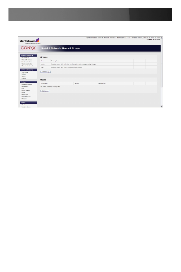
Add / Edit Users
The Administrator uses this menu selection to set up, edit and delete Users and to define the access permissions for each of these Users.
Users can be authorized to access specified ECS0016 serial ports and
specified network attached hosts. These Users can also be given full
Administrator status (with full configuration and management and access
privileges).
To simplify User set up, individual users can be configured as members of
Groups. There are two Groups set up by default:
admin which provides User members with full Administrator privileges
and
users which provides User members with access to the Management
section of the Management Console
22
Page 30
Instruction Manual
Select 1. Serial & Network: Users & Groups to display the configured
Groups and Users
Click 2. Add Group.
Add a 3. Group name and Description for each new Group, then select
Accessible Hosts and Accessible Ports to specify the serial ports
and hosts you wish any Users in this new Group to be able to access.
Click 4. Apply
Select 1. Serial & Network: Users to display the configured Users.
Click 2. Add User to add a new User.
Add a 3. Username and a confirmed Password for each new User. You
may also include information related to the User (e.g. contact details) in
the Description field.
Select 4. Accessible Hosts and Accessible Ports, to specify which
serial ports and to which LAN connected hosts you wish the User to
have access.
Specify the 5. Group (or Groups) of which you wish the User to be a
member.
Click 6. Apply to save changes.
Your new User will now be able to access the selected LAN devices and
the devices attached to the chosen serial ports.
23
Page 31

Instruction Manual
The Administrator can also edit the Access settings for any existing Users. To do so:
Select 1. Serial & Network: Users & Groups
Click 2. Edit for the User to be modified.
Authentication
For details on authentication, please refer to the section titled Remote
Authentication Configuration.
Please note: There are no limits to the number of Users you can set up,
or on the number of Users per serial port or host. As such, multiple Users
(and the Administrator) can control /monitor the one port or host.
Each User can be a member of a number of Groups, in which case they
take on the cumulative access privileges of each of those Groups. A
User may not be a member of any Groups (however if the User is not
even a member of the default user group, they will not be able to use the
ECS0016 Management Console to manage ports.
24
Page 32

Instruction Manual
Network Hosts
To access a locally networked computer or appliance (referred to as a
Host) you must identify the network connected Host, then specify the TCP
or UDP ports/services that will be used to control that Host.
Selecting Serial & Network: Network Hosts presents all of the network
connected Hosts that have been enabled for access, as well as the
related access TCP ports/services.
Click • Add Host to enable access to a new Host (or select Edit to up
date the settings for existing Host)
Enter the • IP Address or DNS Name of the new network connected
Host (and optionally enter a Description)
Add or edit the Permitted Services (or TCP/UDP port numbers) that •
are authorized to be used in controlling this host. Only these permitted
services will be forwarded through by MetaConnect to the Host. All
other services (TCP/UDP ports) will be blocked.
Optional:• Select Nagios Enabled if the service on the Host is to be
monitored using the ECS0016 distributed Nagios monitoring.
The • Logging Level specifies the level of information to be logged and
monitored for each Host access.
If the Host is a networked server with IPMI power control, then the •
Administrator can enable users (Users and Administrators) to remotely
cycle power and reboot.
Click Apply once the desired changes have been made.
25
Page 33

Instruction Manual
Trusted Networks
The Trusted Networks utility provides the option to select specific IP
addresses at which users (Administrators and Users) must be located,
in order to have access to the ECS0016 serial ports. To add an address
designation:
Select 1. Serial & Network: Trusted Networks.
To add a new trusted network, select 2. Add Rule.
Select the 3. Accessible Port(s) to which the new rule is to be applied.
Enter the 4. Network Address of the subnet to be granted access.
Specify the range of addresses that are to be permitted by entering a 5.
Network Mask for that permitted IP range. For example:
To permit all the users located with a par ticular Class C network •
(e.g. 204.15.5.0) connection to the selected port then you would add
the following Trusted Network New Rule:
Network IP Address: 204.15.5.0
Subnet Mask: 255.255.255.0
If you want to permit only one user located at a specific IP •
address (e.g. 204.15.5.13) to connect:
Network IP Address: 204.15.5.0
Subnet Mask: 255.255.255.255
If however you want to allow all the users operating from within a •
specific range of IP addresses (e.g. any address within
204.15.5.129 to 204.15.5.158) to be permitted connection to the
nominated port:
26
Page 34

Instruction Manual
Network IP Address: 204.15.5.128
Subnet Mask: 255.255.255.224
Click 6. Apply.
The above Trusted Networks will limit access by Users and the Administrator, to the ECS0016 serial ports and network attached hosts, however
they do not restrict access by the Administrator to the ECS0016 console
server itself. To change the default settings for this access, you will need
to edit the IP tables rules (as described in the Advanced section).
Serial Port Cascading
Cascaded Ports enables you to cluster distributed console servers so a
large number of serial ports (up to 1000) can be configured and accessed
through one IP address and managed through the one Management Console. One console server, the Master, controls other console servers as
Slave units and all the serial ports on the Slave units appear as if they are
part of the Master.
ECS0016 clustering connects each Slave to the Master with an SSH connection. This is done using public key authentication so the Master can
access each Slave using the SSH key pair (rather than using passwords).
This ensures secure authenticated communications between Master and
Slaves enabling the Slave console server units to be distributed locally on
a LAN or remotely around the world.
To set up public key authentication you must first upload your RSA or
DSA key pair into the Master console server. Please note: If you do not
already have RSA or DSA key pair you will need to create a key pair using ssh keygen, PuTTYgen or a similar tool as detailed in xxxxxxxxxx
Select 1. System: Administration on Master’s Management Console
Browse to the location you have stored RSA (or DSA) Public Key and 2.
upload it to SSH RSA (DSA) Public Key
Browse to the stored RSA (or DSA) Private Key and upload it to SSH 3.
RSA (DSA) Private Key
Click 4. Apply
27
Page 35

Instruction Manual
Next, you must register the Public Key as an Authorized Key on the 5.
Slave. In the simple case with only one Master with multiple Slaves,
you need only upload the one RSA or DSA public key for each Slave.
Please note: The use of key pairs can be confusing as in many cases
one file (Public Key) fulfills two roles – Public Key and Authorized Key.
Select 6. System: Administration on the Slave’s Management Console.
Browse again to the stored RSA (or DSA) Public Key and upload it to 7.
Slave’s SSH Authorized Key.
Click 8. Apply
28
Page 36

Instruction Manual
The next step is to Fingerprint each new Slave-Master connection, which
will authenticate you as a legitimate user for the SSH session. On the first
connection the Slave will receive a fingerprint from the Master which will
be used on all future connections.
To establish the fingerprint, first log in the Master server as root and •
establish an SSH connection to the Slave remote host:
# ssh remhost
Once the SSH connection has been established you will be asked to •
accept the key. Answer Yes and the fingerprint will be added to the list
of known hosts.
If you are asked to supply a password, then there has been a •
problem with uploading keys. The keys should remove any need to
supply a password.
You can now begin setting up the Slaves and configuring Slave serial
ports from the Master console server:
Select Serial & Network: Cascaded Ports on the Master’s Management •
Console. To add clustering support select Add Slave
To define and configure a Slave:
Enter the remote IP Address (or DNS Name) for the Slave console 1.
server
Enter a brief Description and a short Label for the Slave (use a 2.
convention here that enables effective management of large networks
29
Page 37

Instruction Manual
of clustered console servers and the connected devices)
Enter the full number of serial ports on the Slave unit in Number of 3.
Ports
Click Apply. This will establish the SSH tunnel between the Master and 4.
the new Slave
The Serial & Network: Cascaded Ports menu displays all of the Slaves
and the port numbers that have been allocated on the Master. If the Master console server has 16 ports of its own, then ports 1-16 are preallocated to the Master, so the first Slave added will be assigned por t number
17 onwards.
Once you have added all the Slave console servers, the Slave serial ports
and the connected devices are configurable and accessible from the Master’s Management Console menu and accessible through the Master’s IP
address. For example:
Select the appropriate • Serial & Network: Serial Port and Edit to
configure the serial ports on the Slave
Select the appropriate • Serial & Network: Users & Groups to add new
users with access privileges to the Slave serial ports (or to extend
existing users access privileges)
Select the appropriate • Serial & Network: Trusted Networks to specify
network addresses that can access selected Slave serial ports
Select the appropriate • Alerts & Logging: Alerts to configure Slave
port Connection, State Change or Pattern Match alerts
All such configuration changes made on the Master are propagated out to
all the Slaves; whenever you change any User privileges or edit any serial
port setting on the Master, the updated configuration files will be sent out
to each Slave in parallel. The Slaves will then make appropriate changes
to their local configurations (i.e. only make those changes that relate to its
particular serial ports).
Please note:
The Master is in control. You can still change all the settings on any •
Slave serial port (such as alter the baud rates) using the local Slave
Management Console, however these changes will be overwritten the
30
Page 38

Instruction Manual
next time the Master sends out a configuration file update.
Also, while the Master is in control of all Slave serial port related •
functions, it is not Master over the Slave network host connections or
over the Slave console server system itself.
Slave functions such as IP, SMTP & SNMP Settings, Date &Time, •
DHCP server must be managed by accessing each Salve directly and
these functions are not over written when configuration changes are
propagated from the Master. Similarly the Slaves Network Host and
IPMI settings have to be configured at each Slave. network and
transmits it to the pseudo tty port.
31
Page 39

Instruction Manual
Remote Power Control (RPC)
The ECS0016 Management Console monitors and controls Remote
Power Control devices using the embedded PowerMan open source
management tool. RPCs include power distribution units (PDUs) and IPMI
power devices.
Serial PDUs invariably can be controlled using their command line
console, so you could manage the PDU through the ECS0016 using
a remote Telnet client. Also, you could use proprietary software tools
supplied by the vendor. This generally runs on a remote Windows PC
and you could configure the console server serial port to operate with
a serial COM port redirector in the PC. Similarly, network-attached
PDUs with browser controls can be controlled by directly sending HTTP/
HTTPS commands. Also servers and network-attached appliances with
embedded IPMI service processors or BMCs invariably are supplied
with their own management tools (like SoL) that will provide secure
management when connected using with SDT Connector.
However for simplicity all these devices can also be controlled using the
Management Console’s RPC remote power control tools.
RPC Connection
Serial and network connected RPCs must first be connected to, and
configured to communicate with the console server:
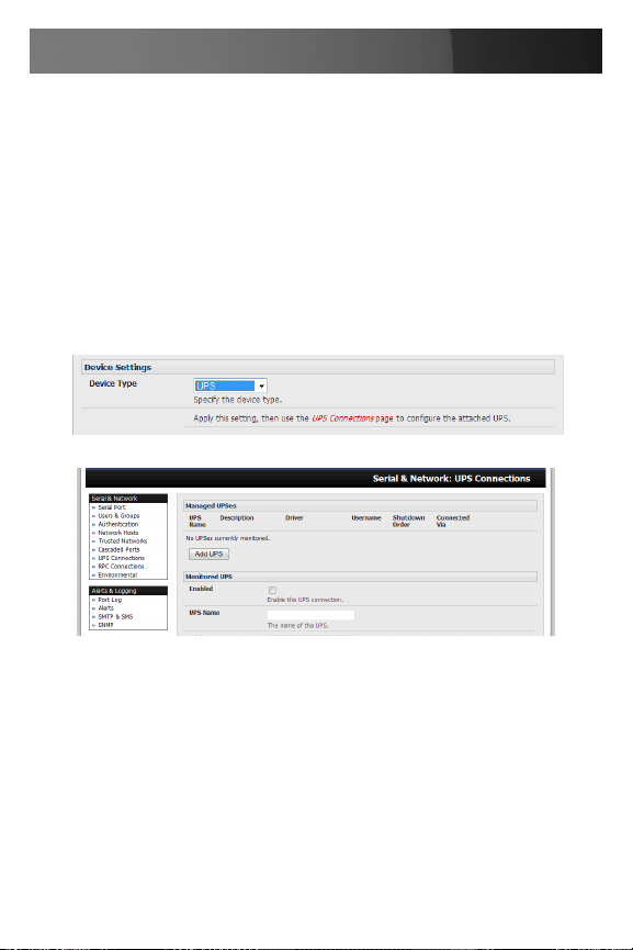
For serial RPCs connect the PDU to the selected serial port on 1.
the ECS0016 and from the Serial and Network: Serial Port menu
configure the Common Settings of that port with the RS232 properties
etc required by the PDU. Then select RPC as the Device Type.
Similarly for each network connected RPC go to Serial & Network: 2.
Network Hosts menu and configure the RPC as a connected Host.
32
Page 40

Instruction Manual
Select the Serial & Network: RPC Connections menu. This will display 3.
all the RPC connections that have already been configured.
Click Add RPC.4.
Enter a RPC Name and Description for the RPC.5.
In “Connected Via” select the pre-configured serial port or the network 6.
host address that connects to the RPC.
Select any specific labels you wish to apply to specific RPC Outlets 7.
(e.g. the PDU may have 20 outlets connected to 20 powered devices
you may wish to identify by name).
33
Page 41

Instruction Manual
Enter the Username and Password used to login into the RPC (Note 8.
that these login credentials are not related the Users and access
privileges you will have configured in Serial & Networks: Users &
Groups).
Check Log Status and specify the Log Rate (minutes between 9.
samples) if you wish the status from this RPC to be logged. These logs
can be views from the Status: RPC Status screen.
Click Apply.10.
Note: The Management Console has support for a growing number of
popular network and serial PDUs. If your PDU is not on the default list it is
simple to add support for more devices.
IPMI service processors and BMCs can be configured so all authorized
users can use the Management Console to remotely cycle power and
reboot computers, even when their operating system is unresponsive. To
set up IPMI power control, the Administrator first enters the IP address/
domain name of the BMC or service processor (e.g. a Dell DRAC) in
Serial & Network: Network Hosts, then in Serial & Network: RPC
Connections specifies the RPC Type to be IPMI1.5 or 2.0
RPC Alerts
You can now set PDU and IPMI alerts using Alerts & Logging: Alerts
RPC Status
You can monitor the current status of your network and serially connected
PDUs and IPMI RPCs
Select the 1. Status: RPC Status menu and a table with the summary
status of all connected RPC hardware will be displayed
34
Page 42

Instruction Manual
Click on View Log or select the 2. RPCLogs menu and you will be
presented with a table of the history and detailed graphical information
on the select RPC
Click 3. Manage to query or control the individual power outlet. This will
take you to the Manage: Power screen
User Power Management
The Power Manager enables both Users and Administrators to access
and control the configured serial and network attached PDU power strips,
and servers with embedded IPMI service processors or BMCs:
Select the Manage: Power and the particular Target power device to be
controlled (or click Manage on the Status: RPC Status menu)
35
Page 43

Instruction Manual
The outlet status is displayed and you can initiate the desired Action to be
taken by selecting the appropriate icon:
Power ON
Power OFF
Power Cycle
Power Status
You will only be presented with icons for those operations that are
supported by the Target you have selected.
Uninterruptible Power Supply Control (UPS)
The ECS0016 console server can manage UPS hardware using Network
UPS Tools.
Managed UPS Connections
A Managed UPS is a UPS that is connected by serial or USB cable or
by the network to the console server. The console server becomes the
master of this UPS, and runs a upsd server to allow other computers that
are drawing power through the UPS (slaves) to monitor its status and take
appropriate action (such as shutdown in event of low battery).
36
Page 44
Instruction Manual
The console server may or may not be drawing power through the
Managed UPS (see the Configure UPS powering the console server
section below).
When the UPS’s battery power reaches critical, the console server
signals and waits for slaves to shutdown, then powers off the UPS.
Serial and network connected UPSes must first be configured on the
console server with the relevant serial control ports reserved for UPS
usage, or the with the UPS allocated as a connected Host:
Select UPS as the Device Type in the 1. Serial & Network: Serial Port
menu for each port which has Master control over a UPS and in the
Serial & Network: Network Hosts menu for each network connected
UPS.
No such configuration is required for USB connected UPS hardware.
Select the 2. Serial & Network: UPS Connections menu. The Managed
UPSes section will display all the UPS connections that have already
been configured.
Click Add UPS 3.
37
Page 45

Instruction Manual
Enter a 4. UPS Name and Description (optional) and the select if the
UPS will be Connected Via USB or over pre-configured serial port or
via HTTP/HTTPS over the preconfigured network Host connection
Enter the UPS login details. This Username and Password is used by 5.
slaves of this UPS (i.e. other computers that are drawing power through
this UPS) to connect to the console server to monitor the UPS status
and shut themselves down when battery power is low. Monitoring will
typically be performed using the upsmon client running on the slave
server. See section 8.5.4 for details on setting up upsmon on slave
servers powered by the UPS
Note: These login credentials are not related the Users and access
privileges you will have configured in Serial & Networks: Users &
Groups
If you have multiple UPSes and require them to be shut down in a 6.
specific order, specify the Shutdown Order for this UPS. This is a whole
38
Page 46

Instruction Manual
positive number, or -1. 0s are shut down first, then 1s, 2s, etc. -1s are
not shut down at all. Defaults to 0
Select the Driver that will be used to communicate with the UPS. 7.
The drop down menu presents full selection of drivers from the latest
Network UPS Tools (NUT version 2.2.0) and additional information on
compatible Ups hardware can be found at http://www.networkupstools.
org/compat/stable.html
Click 8. New Options in Driver Options if you need to set driver-specific
options for your selected NUT driver and hardware combination (more
details at http://www.networkupstools.org/doc)
Check 9. Log Status an specify the Log Rate (minutes between
samples) if you wish the status from this UPS to be logged. These logs
can be views from the Status: UPS Status screen
Check Enable Nagios to enable this UPS to be monitored using 10.
Nagios central management
Click Apply11.
You can also customize the upsmon, upsd and upsc settings for this UPS
hardware directly from the command line
Configure UPS Powering the Console Server
A Monitored UPS is a UPS that the ECS0016 is drawing power through.
The purpose of configuring a Monitored UPS is in the event of a power
failure, it provides an opportunity to perform any “last gasp” actions before
power is lost. This is achieved by placing a script in /etc/config/scripts/
ups-shutdown - you may use the /etc/scripts/ups-shutdown as a template.
This script is run when then UPS reaches critical battery status.
39
Page 47

Instruction Manual
If the ECS0016 is drawing power through a Managed UPS that has
already been configured, select Local, enter the Managed UPS Name
and check Enabled. The ECS0016 continues to be the master of this
UPS.
If the UPS that powers the console server is not a Managed UPS for that
console server, then then console server can still connect to a remote
NUT server (upsd) to monitor its status as a slave. In this case, select
Remote, and enter the address, username and password to connect.
40
Page 48

Instruction Manual
Configuring Powered Computers to Monitor a Managed UPS
Once you have added a Managed UPS, each server that is drawing
power through the UPS should be setup to monitor the UPS status as
a slave. This is done by installing the NUT package on each server, and
setting up upsmon to connect to the ECS0016.
Refer to the NUT documentation for details on how this is done,
specifically sections 13.5 to 13.10. http://eu1.networkupstools.org/
doc/2.2.0/INSTALL.html
An example upsmon.conf entry might look like:
MONITORmanagedups@192.168.0.11usernamepasswordslave
- managedups is the UPS Name of the Managed UPS
- 192.168.0.1 is the IP address of the ECS0016
- 1 indicates the server has a single power supply attached to this UPS
41
Page 49

Instruction Manual
- username is the Username of the Managed UPS
- password is the Password of the Manager UPS
UPS Alerts
You can now set UPS alerts using Alerts & Logging: Alerts
UPS Status
You can monitor the current status of all of your network, serially or USB
connected Managed UPSes or any Monitored UPS
Select the 1. Status: UPS Status menu and a table with the summary
status of all connected UPS hardware will be displayed
Click on any particular UPS System name in the table and you will be 2.
presented with a more detailed graphical information on the select UPS
System
Click on any particular All Data for any UPS System in the table for 3.
more status and configuration information on the select UPS System
42
Page 50

Instruction Manual
Select UPS Logs and you will be presented with the log table of the 4.
load, battery charge level. temperature and other status information
from all the Managed and Monitored UPS systems. This information
will be logged for all UPSes which were configured with Log Status
checked. The information is also presented graphically
Overview of Network UPS Tools (NUT)
Network UPS Tools (NUT) is a group of open source programs that
provide a common interface for monitoring and administering UPS
hardware; and ensuring safe shutdowns of the systems which are
connected.
NUT can be configured using the Management Console as described
above, or you can configure the tools and manage the UPSes directly
from the command line. This section provides an overview of NUT
however you can find full documentation at http://www.networkupstools.
org/doc.
43
Page 51

Instruction Manual
NUT is built on a networked model with a layered scheme of drivers,
server and clients.
The driver programs talk directly to the UPS equipment and run on 1.
the same host as the NUT network server upsd. Drivers are provided
for a wide assortment of equipment from most of the popular UPS
vendors and they understand the specific language of each UPS and
map it back to a compatibility layer. This means both an expensive
“smart” protocol UPS and a simple “power strip” model can be handled
transparently.
The NUT network server program upsd is responsible for passing 2.
status data from the drivers to the client programs via the network.
upsd can caches the status from multiple UPSes and can then serve
this status data to many clients. upsd also contains access control
features to limit the abilities of the clients (e.g. so only authorized hosts
may monitor or control the UPS hardware)
There are a number of NUT clients that connect to upsd that to read 3.
that check on the status of the UPS hardware and do things based
on the status. These clients can run on the same host as the NUT
server or they can communicate with the NUT server over the network
(enabling them to monitor any UPS anywhere).
The upsmon client enables servers that draw power through the UPS
(i.e. slaves of the UPS) to shutdown gracefully when the battery power
reaches critical. Additionally, one server is designated the master of
the UPS, and is responsible for shutting down the UPS itself when all
slaves have shut down. Typically, the master of the UPS is the one
connected to the UPS via serial or USB cable.
upsmon can monitor multiple UPSes, so for high-end servers which
receive power from multiple UPSes simultaneously won’t initiate a
shutdown until the total power situation across all source UPSes
becomes critical.
There also the two status/logging clients, upsc and upslog. The upsc
client provides as a quick way to poll the status of a UPS. It can be
used inside shell scripts and other programs that need UPS status
information. upslog is a background service that periodically polls the
44
Page 52

Instruction Manual
status of a UPS, writing it to a file.
All these clients all run on the ECS0016 (for Management Console
presentations) but they also are run remotely (on locally powered
servers and remote monitoring systems).
This layered NUT architecture enables:
Multiple manufacturer support: • NUT can monitor USB models from
79 different manufacturers with a unified interface
Multiple architecture support: • NUT can manage serial and USB
connected models with the same common interface. SNMP equipment
can also be monitored (although at this stage this is still pre-release
with experimental drivers and this feature will be added to the
ECS0016’s embedded UPS tools in future release).
Multiple clients monitoring the one UPS:• Multiple systems may
monitor a single UPS using only their network connections and there’s
a wide selection of client programs) which support monitoring UPS
hardware via NUT (Big Sister, Cacti, Nagios, Windows and more. Refer
www.networkupstools.org/client-projects.)
So NUT supports the more complex power architectures found in data
centers, computer rooms and NOCs where many UPSes from many
vendors power many systems with many clients and each of the larger
UPSes power multiple devices and many of these devices are themselves
dual powered.
Environmental Monitoring
The Environmental Monitor Device (EMD) connects to any ECS0016
serial port and each console server can support multiple EMDs. Each
EMD device has one temperature and one humidity sensor and two
general purpose status sensors which can be connected to a smoke
detector, water detector, vibration or open-door sensor.
45
Page 53

Instruction Manual
Using the Management Console, Administrators can view the ambient
temperature and humidity and set the EMD to automatically send alarms
progressively from warning levels to critical alerts.
Connecting the EMD
The Environmental Monitor Device (EMD) connects to any serial port on
the console server via a special EMD Adapter and standard CAT5 cable.
The EMD is powered over this serial connection and communicates using
a custom handshake protocol. It is not an RS232 device and should not
be connected without the adapter:
Plug the male RJ plug on the EMD Adapter into EMD and then connect 1.
to the console server serial port using the provided UTP cable. If the
6 foot (2 meter) UTP cable provided with the EMD is not long enough
it can be replaced with a standard Cat5 UTP cable up to 33 feet (10
meters) in length
46
Page 54

Instruction Manual
Screw the bare wires on any smoke detector, 2.
water detector, vibration sensor, open-door
sensor or general purpose open/close status
sensors into the terminals on the EMD
The EMD can be used only with an ECS0016 and cannot be connected
to standard RS232 serial ports on other appliances.
Select Environmental as the Device Type in the 1. Serial & Network:
Serial Port menu for the port to which the EMD is to be attached. No
particular Common Settings are required.
Click Apply.2.
Select the 3. Serial & Network: Environmental menu. This will display
all the EMD connections that have already been configured.
Click Add.4.
47
Page 55

Instruction Manual
Enter a 5. Name and Description for the EMD and select pre-configured
serial port that the EMD will be “Connected Via”.
Provide 6. Labels for each of the two alarms
Check 7. Log Status and specify the Log Rate (minutes between
samples) if you wish the status from this EMD to be logged. These logs
can be views from the Status: Environmental Status screen
Click Apply 8.
Environmental Alerts
You can now set temperature, humidity and probe status alerts using
Alerts & Logging: Alerts
48
Page 56

Instruction Manual
Environmental Status
You can monitor the current status of all of EMDs and their probes
Select the 1. Status: Environmental Status menu and a table with the
summary status of all connected EMD hardware will be displayed
Click on View Log or select the 2. Environmental Logs menu and you
will be presented with a table and graphical plot of the log history of the
select EMD
49
Page 57

Instruction Manual
Failover and Out-of-Band Dial Access
The ECS0016 has a number of failover and out-of-band access capabilities to ensure high availability.
If there are difficulties in accessing the gateway through the principal •
network path, the Administrator can access the ECS0016 out-of-band
(OoB) from a remote location, using a dialup modem/ISDN connection
The ECS0016 can also be accessed out-of-band (OoB) using an •
alternate broadband link
ECS0016 gateways also offer broadband failover, so in the event of a •
disruption to the principal management network connection, access is
switched transparently to the standby network connection
The ECS0016 can also be configured for out-dial failover, so in the •
event of a disruption in the principal management network, an external
dial up ppp connection is established
OoB Dial-In access
To enable OoB dial-in access, you first configure the ECS0016 gateway
(and once set up for dial-in PPP access, the gateway will await an incoming connection from a dial-in at remote site). Then set up the remote client
dial-in software so it can establish a network connection from the Administrator’s client modem to the dial in modem on the ECS0016.
50
Page 58

Instruction Manual
Please note: The ECS0016 requires an external modem attached (via a
serial cable) to the DB9 port (marked Local, located on the front panel).
Configure Dial In PPP
To enable dial-in PPP access on the ECS0016 console/modem port:
Select the 1. System: Dial menu option and the port to be configured
(Serial DB9 Port or Internal Modem Port). The ECS0016 console/
modem serial port is set by default to 115200 baud, No parity, 8 data
bits and 1 stop bit, with software (XonXoff) flow control enabled. When
enabling OoB dial-in on ECS0016 units, it is recommended that this be
changed to 38,4000 baud with Hardware Flow Control.
Select the 2. Baud Rate and Flow Control that will communicate with
the modem. You can further configure the console/modem port (e.g. to
include modem init strings) by editing /etc/mgetty.config files.
Check the3. Enable Dial In Access box.
Enter the 4. User name and Password to be used for the dial-in PPP
link.
In the 5. Remote Address field, enter the IP address to be assigned to
the dial-in client. You can select any address for the Remote IP
Address, however it and the Local IP Address, must both be in the
same network range (e.g. 200.100.1.12 - 200.100.1.67)
In the Local Address field enter the IP address for the Dial-In PPP
Server. This is the IP address that will be used by the remote client to
access ECS0016, once the modem connection is established. Any
address within the IP range of the Remote IP Address can be used
(e.g. 200.100.1.12 - 200.100.1.67) addresses must be in the same
network range as the Remote IP Address.
The • Default Route option enables the dialed PPP connection to
become the default route for the ECS0016 gateway.
The • Custom Modem Initialization option allows a custom AT string
modem initialization string to be entered (e.g. AT&C1&D3&K3)
51
Page 59

Instruction Manual
Select the 6. Authentication Type to be applied to the dial-in connection.
The ECS0016 uses authentication to challenge Administrators who •
dial-in to the gateway. (For dial-in access, the username and
pass word received from the dial-in client are verified against the
local authentication database stored on the ECS0016). The
Administrator must also have their client PC / workstation configured
to use the selected authentication scheme.
Select 7. PAP, CHAP, MSCHAPv2 or None and click Apply.
None• - With this selection, no username or password authentication
is required for dial-in access. This is not recommended.
PAP - • Password Authentication Protocol (PAP) is the usual method
of user authentication used on the internet: sending a username and
password to a server where they are compared with a table of
authorized users. Whilst most common, PAP is the least secure of
the authentication options.
CHAP -• Challenge Handshake Authentication Protocol (CHAP) is
used to verify a user’s name and password for PPP Internet
connections. It is more secure than PAP, the other main
authentication protocol.
MSCHAPv2• - Microsoft Challenge Handshake Authentication
Protocol (MSCHAP) is authentication for PPP connections between
a computer using a Microsoft Windows operating system and a
network access server. It is more secure than PAP or CHAP, and is
the only option that also supports data encryption
52
Page 60

Instruction Manual
ECS0016 gateways also support dial-back for additional security. Check
the Enable Dial Back box and enter the phone number to be called to reestablish an OoB link, once a dial-in connection has been logged.
Using The MetaConnect client
Administrators can use the MetaConnect Java client software to set up
secure OoB dial-in access to remote ECS0016 gateways. OoB access
uses a different path for connecting to the gateway than that which is
used for regular data traffic.
Starting an OoB connection in MetaConnect may be achieved by initiating
a dial up connection, or adding an alternate route to the gateway, while
allowing you to provide your own scripts or commands for starting and
stopping the OoB connection.
Set up Windows XP/ 2003 client
Open 1. Network Connections in Control Panel and click the New
Connection Wizard.
Select 2. Connect to the Internet and click Next.
On the 3. Getting Ready screen select Set up my connection manually
and click Next.
On the Internet Connection screen select 4. Connect using a dial-up
modem and click Next.
Enter a Connection Name (any name you choose) and the dial-up 5.
Phone number that will connect thru to the ECS0016 modem
Enter the 6. PPP User name and Password that are set up for the
ECS0016, select Next, then Finish.
Set up earlier Windows clients
For Windows® 2000, the PPP client set up procedure is the same as
above, except to access the Dial-Up Networking Folder, click the Start
button, select Settings then click Network and Dial-up Connections
followed by Make New Connection.
53
Page 61

Instruction Manual
Similarly for Windows® 98, you double-click My Computer on the Desktop, then open Dial-Up Networking and double-click Make New Con-
nection and proceed as outlined for Windows XP (see previous section).
Set up Linux clients
The online tutorial http://www.yolinux.com/TUTORIALS/LinuxTutorialPPP.
html presents a selection of methods for establishing a dial up PPP connection:
54
Page 62

Instruction Manual
Command line PPP and manual configuration (which works with any •
Linux distribution)
Using the Linuxconf configuration tool (for Red Hat compatible •
distributions). This configures the scripts ifup/ifdown to start and stop
a PPP connection
Using the Gnome control panel configuration tool •
WVDIAL and the Redhat “Dialup configuration tool” •
GUI dial program Xisp. Download/Installation/Configuration•
Note For all PPP clients:
Set the PPP link up with TCP/IP as the only protocol enabled •
Specify that the Server will assign IP address and do DNS •
Do not set up the ECS0016 PPP link as default for Internet connection •
55
Page 63

Instruction Manual
Secure Tunneling & MetaConnect
Serial access to Linux consoles,
Windows EMS/BIOS etc.
Control serial connected firewalls, power
switches and other devices
MetaConnect establishes secure tunnel
to gateway, then Telnet/SSH connection
to serially attached devices
Remote or Local User/
Administrator
Telnet or SSH connection to serially attached devices
MetaConnect can also be used to access text consoles on devices that
are attached to the ECS0016 gateway serial ports. For these connections,
you must configure the MetaConnect client software with a Service that
will access the target gateway serial port, and then set the gateway up as
a host:
Launch MetaConnect on your PC. Select 1. Edit, then Preferences and
click the Services tab. Click Add, then enter “SerialPort2” in Service
Name. Click Add to proceed.
Select 2. Telnet client as the Client. Enter 2002 in TCP Port. Click OK,
56
Page 64

Instruction Manual
then Close and Close again
Assuming you have already set up the target ECS0016 as a gateway 3.
in your MetaConnect client (with username/ password etc), select this
gateway and click the Host icon to create a host (alternatively, select
File > New Host).
Enter 4. 127.0.0.1 as the Host Address and select Serial Port 2 for
Service. In Descriptive Name, enter as appropriate (e.g. Loop
back ports, Local serial ports, etc.). Click OK to continue.
• ClicktheSerialPort2iconforTelnetaccesstotheserialconsoleon
the device attached to serial port #2 on the gateway
To enable MetaConnect to access devices connected to the gateway’s
serial ports, you must also configure the ECS0016 gateway itself to
allow port-forwarded network access to itself, and enable access to the
selected serial port:
Browse to the ECS0016 gateway and select 1. Serial Port from Serial &
Network.
Click 2. Edit next to the selected Port number (e.g. Port 2 if the target
device is attached to the second serial port). Ensure the port’s serial
configuration is appropriate for the attached device.
Scroll down to 3. Console Server Setting and select Console Server
Mode. Check Telnet (or SSH) and scroll to the bottom and click Apply.
Select 4. Network Hosts from Serial & Network and click Add Host.
In the 5. IP Address/DNS Name field enter 127.0.0.1 and enter Loop
back in Description.
Remove all entries under 6. Permitted Services, select TCP and
enter 200+n in Port. (This configures the Telnet port enabled in the
previous steps, so for Port 2 you would enter 2002)
Click 7. Add, then scroll to the bottom and click Apply.
By default, administrators have gateway and serial port access privileges;
however for Users to access the gateway and the serial port, you will
need to give those Users the required access privileges. To do so:
57
Page 65

Instruction Manual
Select 1. Users & Groups from Serial & Network.
Click 2. Add User.
Enter a 3. Username, Description and Password/Confirm.
Select 4. 127.0.0.1 from Accessible Host(s) and select Port 2 from
Accessible Port(s).
Click 5. Apply.
MetaConnect for OoB Connection to the Gateway
MetaConnect can also be set up to connect to the gateway out-of-band
(OoB). OoB access uses a different path for connecting to the gateway
than that which is used for regular data traffic. OoB access is useful for
when the primary link into the gateway is unavailable or unreliable.
Typically a gateway’s primary link is a broadband Internet connection or
Internet connection via a LAN or VPN, and the secondary Out-of-band
connectivity is provided by dialing into a dial-up modem that is directly
attached to the gateway. Out-of-band access enables you to access the
hosts on the network, diagnose any connectivity issues, and restore the
gateway’s primary link.
In MetaConnect, OoB access is configured by providing the secondary
IP address of the gateway, and telling MetaConnect how to start and stop
the OoB connection. Starting an OoB connection in MetaConnect may be
achieved by initiating a dial up connection, or adding an alternate route to
the gateway, while allowing you to provide your own scripts or commands
for starting and stopping the OoB connection.
To configure MetaConnect for OoB access:
When adding a new gateway or editing an existing gateway, select the
Out Of Band tab, then:
Enter the secondary, OoB IP address of the gateway (e.g. the IP 1.
address it is accessible using when dialed in directly). You also may
modify the gateway’s SSH port if it’s not using the default of 22
Enter the command or path to a script to start the OoB connection in 2.
Start Command
58
Page 66

Instruction Manual
To initiate a pre-configured dialup connection under Windows, use the •
following Start Command:
cmd /c start “Starting Out of Band Connection” /wait /min rasdial
network_connection login password
(where network_connection is the name of the network connection
as displayed in Control Panel -> Network Connections, login is the
dial-in username, and password is the dial-in password for the
connection)
To initiate a pre-configured dialup connection under Linux, use the •
following Start Command:
pon network_connection
(where network_connection is the name of the connection)
Enter the command or path to a script to stop the OoB connection 3.
using a Stop Command
To stop a preconfigured dialup connection under Windows, use the •
following Stop Command:
cmd /c start “Stopping Out of Band Connection” /wait /min rasdial
network_connection /disconnect
(where network connection is the name of the network connection as
displayed in Control Panel -> Network Connections)
To stop a preconfigured dialup connection under Linux, use the •
following Stop Command:
poff network_connection
59
Page 67

Instruction Manual
To make the OoB connection using MetaConnect:
Select the gateway from the left hand list of gateways and hosts. Under
Gateway Actions in the right hand pane, click Out Of Band. The status
bar will change color to indicate this gateway is now being accessed using the OoB link, rather than the primary link.
When you connect to a service on a host behind the gateway, or the
gateway itself, MetaConnect will initiate the OoB connection using the
provided Start Command. The OoB connection isn’t stopped (using the
provided Stop Command) until Out Of Band under Gateway Actions is
clicked off, at which point the status bar will return to its normal color.
Importing (and exporting) preferences
To enable the distribution of pre-configured client config files, MetaConnect has an Export/Import facility:
To save a configuration .xml file (for backup or for importing into other •
MetaConnect clients) select File > Export Preferences and select the
location to save the configuration file
To import a configuration select • File -> Import Preferences and select
the .xml configuration file to be installed
MetaConnect Public Key Authentication
MetaConnect can authenticate against an SSH gateway using your SSH
key pair, rather than requiring you to enter your password. This is known
as public key authentication.
To use public key authentication with MetaConnect, first you must add the
public part of your SSH key pair to your SSH gateway:
Ensure the SSH gateway allows public key authentication, this is •
typically the default behavior
If you do not already have a public/private key pair for your client •
PC (the one running MetaConnect) generate them now using
ssh-keygen, PuTTYgen or a similar tool. You may use RSA or DSA,
however it is important that you leave the passphrase field blank.
60
Page 68

Instruction Manual
PuTTYgen:
http://www.chiark.greenend.org.uk/~sgtatham/putty/download.html
OpenSSH:
http://www.openssh.org/
OpenSSH (Windows):
http://sshwindows.sourceforge.net/download/
Upload the public part of your SSH key pair (this file is typically named •
id_rsa.pub or id_dsa.pub) to the SSH gateway, or otherwise add to
.ssh/authorized keys in your home directory on the SSH gateway.
Next, add the private part of your SSH key pair (this file is typically •
named id_rsa or id_dsa) to MetaConnect. Click Edit > Preferences
> Private Keys > Add, then locate the private key file and click OK.
Note that you do not have to add the public part of your SSH key pair, it is
calculated using the private key.
MetaConnect will now use public key authentication when connecting
through the SSH gateway. Note that you may have to restart MetaConnect to shut down any existing tunnels that were established using
password authentication.
Note: If you have a host behind the SSH gateway that you connect to by
clicking the SSH button in MetaConnect you may also wish to configure
access to it for public key authentication as well.
This configuration is entirely independent of MetaConnect and the SSH
gateway. You must configure the SSH client that MetaConnect launches
(e.g. Putty, OpenSSH) and the host’s SSH server for public key authentication. Essentially, what you are using is SSH over SSH, and the two
SSH connections are entirely separate.
Setting up MetaConnect for Remote Desktop access
Microsoft’s Remote Desktop Protocol (RDP) enables the system manager to securely access and manage remote Windows computers – to
reconfigure applications and user profiles, upgrade the server’s operating
61
Page 69

Instruction Manual
system, reboot the machine etc. ECS0016’s Secure Tunneling uses SSH
tunneling, so this RDP traffic is securely transferred through an authenticated and encrypted tunnel.
MetaConnect with RDP also allows remote Users to connect to Windows
XP, Windows 2003 computers and to Windows 2000 Terminal Servers,
and to have access to all of the applications, files, and network resources
(with full graphical interface just as though they were in front of the computer screen at work).
To set up a secure Remote Desktop connection you must enable Remote
Desktop on the target Windows computer that is to be accessed and
configure the RPD client software on the client PC.
Set up MetaConnect Serial Ports on ECS0016
To set up RDP (and VNC) forwarding on the ECS0016 Serial Port that is
connected to the Windows computer COM port:
Secure MetaConnect Tunneled Remote Desktop Connections
Select the • Serial & Network: Serial Port menu option and click Edit
(for the particular Serial Port that is connected to the Windows
computer COM port)
On the MetaConnect Settings menu, select SDT Mode (which will •
enable port forwarding and SSH tunneling) and enter a Username and
User Password.
Note: When you enable MetaConnect, this will override all other Configu-
62
Page 70

Instruction Manual
ration protocols on that port
Note: If you leave the Username and User Password fields blank, they
default to portXX and portXX where XX is the serial port number. The
default username and password for Secure RDP over Port 2 is port02
Ensure the ECS0016 • Common Settings (Baud Rate, Flow Control)
are the same as were set up on the Windows computer COM port and
click Apply
RDP and VNC forwarding over serial ports is enabled on a Port basis. •
You can add Users who can have access to these ports (or reconfigure
User profiles) by selecting the Serial & Network :User & Groups
menu tag
SSH port forward over the ECS0016 Serial Port
In the MetaConnect software running on your remote computer, specify 1.
the gateway IP address of your ECS0016 and a username/password
for a user you have setup on the ECS0016 that has access to the
desired port.
Next you need to add a New MetaConnect Host. In the Host address, 2.
you need to enter portxx where xx = the port to which you are
connecting. (e.g. for Port 3 you would have a Host Address of: port03)
Select the RDP Service check box.3.
63
Page 71

Instruction Manual
Alerts and Logging
This chapter describes the logging and alert generation features of the
console server. The Alert facility monitors the serial ports, all logins and
the power status and sends emails or Nagios or SNMP alerts when specified trigger events occurs:
First, you must enable and configure the service that will be used to carry
the alert then specify the alert trigger condition and the actual destination
to which that particular alert is to be sent.
The Port Logging can maintain a record of all access and communications with the ECS0016 and with the attached serial devices. A log of all
system activity is also maintained.
If port logs are to be maintained on a remote server, then the access •
path to this location need to be configured. Then, you need to activate
and set the desired levels of logging for each serial or network port
or Managed UPS
Enable SMTP, SNMP and/or Nagios
The Alerts facility monitors nominated ports/hosts for trigger conditions.
When triggered an Alert message is emailed to a nominated email address (SMTP), or sent to a designated SNMP destination or sent to the
central Nagios server for action. Before setting up the alert trigger, you
must specify these alert destinations.
Email alerts
To set up the email alert destination:
Select Alerts & Logging: SMTP and in the Server field enter the IP 1.
address of the outgoing mail server
You may optionally enter an Sender email address which will •
appear as the ‘from’ address in all sent email from this ECS0016
Click 2. Apply to activate SMTP.
64
Page 72

Instruction Manual
SNMP alerts
The Administrator can configure the Simple Network Management Protocol (SNMP) agent that resides on the console server, to send Alerts to an
SNMP management application:
Select 1. Alerts & Logging: SNMP.
Enter the SNMP transport protocol. SNMP is generally a UDPbased 2.
protocol though infrequently it uses TCP instead.
Enter the IP address of the SNMP Manager and the Port to used for 3.
connection.
Select the version being used. The console server SNMP agent 4.
supports SNMP v1, v2 and v3
Enter the Community name for SNMP v1 or 2c 5.
To configure for SNMP v3 you will need to enter an ID and 6.
authentication password and contact information for the local
Administrator (in the Security Name)
Click Apply to activate SNMP 7.
Nagios Alerts
To notify the central Nagios server of Alerts, NSCA must be enabled
under System: Nagios and Nagios must be enabled for each applicable
host or port under Serial & Network: Network Hosts or : Serial Ports
Configure Alerts
The Alerts facility monitors the status of the console server and connected devices and when an alert event is triggered, an Alert message is then
65
Page 73

Instruction Manual
emailed to a nominated email address, or the SNMP or Nagios server is
notified. The data stream from nominated serial por ts can be monitored
for matched patterns or flow control status changes can be configured to
trigger alerts. As can user connections to serial ports and Hosts, or power
events.
Select 1. Alerts & Logging: Alerts which will display all the alerts
currently configured. Click Add Alert.
At 2. Add a New Alert enter a Description for the alert or trigger
condition.
Select the email address for the Email Recipient who will be notified 3.
of the alert, and/or activate SNMP notification for this event.
Select the 4. Applicable Ports (serial) and/or Hosts and/or UPS that is
(are) to be monitored for this alert trigger
In a MetaConnect Nagios centrally managed environment, you can check
the Nagios alert option. On the trigger condition (for matched patterns, logins, power events and signal changes) an NSCA check “warning” result
will be sent to the central Nagios server. This condition is displayed on
the Nagios status screen and triggers a notification, which can cause the
Nagios central server itself to send out an email or an SMS, page, etc
Next, you must select the AlertType (Connection, Signal, Pattern Match
or Power) that is to be monitored. Also you can configure a selection of
different Alert types and any number of specific Alert triggers for each
serial port
Connection Alert: This alert will be triggered when a user connects or
66
Page 74

Instruction Manual
disconnects from the applicable Host or Serial Port, or when a Slave connects or disconnects from the applicable UPS
Serial Port Signal Alert: This alert will be triggered when the specified signal changes state and is applicable to serial ports only. You must
specify the particular Signal Type (DSR, DCD or CTS) trigger condition
that will send a new alert
Serial Port Pattern Match Alert: This alert will be triggered if a regular
expression is found in the serial ports character stream that matches the
regular expression you enter in the Pattern field. This alert type will only
be applied serial ports
UPS Power Status Alert: This alert will be triggered when the UPS
power status changes between on line, on battery, and low battery. This
alert type will only be applied to UPSes.
Click Apply, once you’ve made your selection(s).
Remote Log Storage
Before activating Serial or Network Port Logging on any port or UPS logging, you must specify where those logs are to be saved:
Select the • Alerts & Logging: Port Log menu option and specify the
Server Type to be used as well as the details to enable log server
access
Serial Port Logging
In Console Server mode, activity logs can be maintained of all serial
67
Page 75

Instruction Manual
port activity. These records are stored on an ‘offserver’. To specify which
serial ports are to have activities recorded and to what level data is to be
logged:
Select 1. Serial & Network: Serial Port and Edit the port to be logged.
Specify the 2. Logging Level of for each port as:
Level 0• Turns off logging for the selected port
Level 1• Logs all connection events to the port
Level 2• Logs all data transferred to and from the port and all
changes in hardware flow control status and all User
connection events
Click 3. Apply
Please Note: A cache of the most recent 8K of logged data per serial
port is maintained locally (in addition to the Logs which are transmitted for
remote/USB flash storage). To view the local cache of logged serial port
data select Manage: Port Logs.
Power Control
Users and Administrators can use their ECS0016 gateways to remotely
power on, power off, power cycle and read the current status of power
strips, UPS supplies and servers:
Serial port controlled power strips can be controlled by using their •
command line console. However, these serial port controlled power
strips can also be securely accessed and controlled using the
Management Console’s power control tools
Network attached power strips with browser controls can be •
controlled by directly sending HTTP/HTTPS commands with
MetaConnect. Alternately, these browser controlled power strips can
be securely accessed and controlled using the Management
Console’s power control tools.
Servers and network attached appliances with embedded IPMI •
service processors or BMCs invariably are supplied with their own
management tools (like SoL) that will provide secure management
68
Page 76

Instruction Manual
when connected using MetaConnect. These IPMI controlled power
switches can also be controlled using the Management Console’s
power control tools
Servers with embedded service processors (such as Dell’s DRAC) •
usually provide power control using the browser based management
applications that are supplied with the service processor (such as
Dell’s Open Manage) – and these applications invariably can be
connected (securely in and outofband) using MetaConnect
The ECS0016 embeds the Network UPS Tools (NUT), enabling you •
to manage serially connected and USB connected Uninterruptible
Power Supply (UPS) hardware. You can configure the NUT tools
and manage the UPSes directly from the command line or using the
Management Console.
69
Page 77

Instruction Manual
Configuring Serial Port Power Strips
The Administrator can configure serially connected power strips, so both
Users and Administrators can control them directly using the Management Console. First, the selected gateway serial port must be connected
to and configured to communicate with the power strip:
Connect the power strip to the selected serial port on the ECS0016 1.
gateway
Select the 2. Serial and Network: Serial menu option and configure the
Common Settings of the selected gateway serial port that will be
connected to the power strip with the RS232 properties etc required by
the power strip.
Select 3. Power Strip Mode, then select the Power Device Type to be
controlled.
To simplify power management, you also can also optionally apply 4.
a text label to each of the power outlets on the power strip you have
installed
Enter the 5. Username and Password for accessing the Power Device.
Click 6. Apply.
Configuring IPMI Power Management
The ECS0016 provides power management of servers, storage and telco
devices built with embedded IPMI service processors and BMCs. The
Administrator can configure these IPMI devices, so both Users and Administrators can use the Management Console to remotely cycle power
and reboot, even when the operating system is unresponsive.
To set up networked server for IPMI power control, the Administrator must
configure the embedded IPMI device to communicate:
Select 1. Serial & Network: Network Hosts and enter the IP Address/
Domain Name of the BMC or Service Processor (e.g. Dell DRAC)
Then in 2. Power Device Settings, specify the IPMI Power Device Type
(1.5 or 2.0) and Username / Password.
Click 3. Apply
70
Page 78

Instruction Manual
Configuring Browser Controlled Power Strips
The Administrator can configure network attached power strips, so both
Users and Administrators can control them directly using the Management Console.
User Power Management
The Power Manager enables both Users and Administrators to access
and control the configured serial and network attached power strips and
servers with embedded IPMI service processors or BMCs:
Select the 1. Manage: Power and the par ticular Target power device to
be controlled.
Then initiate the desired Action to be taken by selecting the appropriate 2.
icon:
Power ON
Power OFF
Power Cycle
Power Status
You will only be presented with icons for those operations that are supported by the Target you have selected.
71
Page 79

Instruction Manual
Nagios Integration
Nagios is a powerful, highly extensible open source tool for monitoring
network hosts and services. The core Nagios software package will typically be installed on a server or virtual server - the central Nagios server.
ECS0016 gateways operate in conjunction with a central/upstream
Nagios server, to provide distributed monitoring of attached network hosts
and serial devices. They embed the NSCA (Nagios Service Checks Acceptor) and NRPE (Nagios Remote Plugin Executor) addons – this allows
them to communicate with the central Nagios server, eliminating the need
for a dedicated slave Nagios server at remote sites.
The ECS0016 supports basic distributed monitoring. Even if distributed
monitoring is not required, the ECS0016 gateways can be deployed locally alongside the Nagios monitoring host server, to provide additional
diagnostics and points of access to managed devices.
StarTech.com’s MetaConnect for Nagios extends the capabilities of the
central Nagios server beyond monitoring, enabling it to be used for central management tasks. It incorporates the MetaConnect client, enabling
point-and-click access and control of distributed networks of ECS0016
gateways as well as their attached network and serial hosts, from a
central location.
Please note: if you have an existing Nagios deployment, you may wish
to use the ECS0016 gateways in a distributed monitoring server capacity
only; if this is the case, skip to the section titled Enable Nagios on the
ECS0016
Nagios overview
Nagios provides central monitoring of the hosts and services in your distributed network. Nagios is freely downloadable, open source software.
This section offers a quick background of Nagios and its capabilities. A
complete overview, FAQ and comprehensive documentation are available
at: http://www.nagios.org
Nagios does take some time to install, but once Nagios is up and running,
72
Page 80

Instruction Manual
it provides an outstanding network monitoring system.
With Nagios you can:
Display tables showing the status of each monitored server and •
network service in real time
Use a wide range of freely available plugins to make detailed checks of •
specific services – e.g. don’t just check that a database is accepting
network connections, check that it can actually validate requests and
return real data
Display warnings and send warning emails, pager or SMS alerts when •
a service failure or degradation is detected
Assign contact groups who are responsible for specific services in •
specific time frames
Central management and setting up MetaConnect for Nagios
The MetaConnect Nagios solution has three parts: Central Nagios
server, Distributed ECS0016 console servers, and SDT for Nagios
clients
Central Nagios server:
A Nagios 2.x or 3.x installation (typically on a Linux server)•
Generally running on a blade, PC, virtual machine, etc. at a central •
location
Runs a web server that displays the Nagios GUI •
Imports configuration from distributed ECS0016 console servers using •
the MetaConnect for Nagios Configuration Wizard
Distributed ECS0016 console servers:
ECS0016 Enhanced Console Server •
Serial and network hosts attached to each console server •
Each runs Nagios plugins, NRPE and NSCA addons, but not a full •
Nagios server
73
Page 81

Instruction Manual
Clients
Typically a client PC, laptop, etc. running Windows, Linux or Mac OS X •
Runs MetaConnect •
Possibly remote to the central Nagios server or distributed ECS0016 •
console servers
May receive alert emails from the central Nagios server or distributed •
ECS0016 console servers
Connects to the central Nagios server web UI to view status of •
monitored hosts and serial devices
Uses MetaConnect to connect through the distributed ECS0016 •
console servers, to manage monitored hosts and serial devices
MetaConnect Nagios setup involves the following steps:
Install Nagios and the NSCA and NRPE addons on the central Nagios 1.
server.
Configure each ECS0016 distributed console server for Nagios 2.
monitoring, alerting, and MetaConnect Nagios integration.
Run the MetaConnect for Nagios Configuration Wizard on the central 3.
Nagios server and perform any additional configuration tasks.
Install MetaConnect on each client.4.
Set Up a Central Nagios Server
MetaConnect for Nagios requires a central Nagios server running Nagios
2.x or 3.x. Nagios 1.x is not supported.
The Nagios server software is available for most major distributions of
Linux using the standard package management tools. Your distribution will
have documentation available on how to install Nagios. This is usually the
quickest and simplest way to get up and running.
Note that you will need the core Nagios server package, and at least one
of the NRPE or NSCA addons. NSCA is required to utilize the alerting features of the distributed hosts, installing both NRPE and NSCA is
recommended.
74
Page 82

Instruction Manual
You will also require a web server such as Apache to display the Nagios
web UI (and this may be installed automatically as a dependency of the
Nagios packages).
Central Site
Nagios
Server
ECS0016
Network
Alternatively, you may wish to download the Nagios source code directly
from the Nagios website, and build and install the software from scratch.
The Nagios website (http://www.nagios.org) has several Quick Start
Guides that walk through this process.
Once you are able to browse to your Nagios server and see its web UI
and the local services it monitors by default, you are ready to continue.
Set up distributed ECS0016 console servers
This section provides a brief walkthrough on configuring a single
ECS0016 console server to monitor the status of one attached network
host (a Windows IIS server running HTTP and HTTPS services), one
serially attached device (the console port of a network router), as well as
to send alerts back to the Nagios server when an administrator connects
to the router or IIS server.
This walkthrough provides an example, however details of the configuration options are described in the next section. This walkthrough also
assumes the network host and serial devices are already physically connected to the console server.
Remote Site
Serial
Managed Hosts
75
Page 83

Instruction Manual
The first step is to set up the Nagios features on the console server:
Select 1. System: Nagios on the ECS0016 Management Console.
Check to make sure the Nagios service is 2. Enabled.
Enter the IP address that the central Nagios server will use to contact 3.
the distributed ECS0016 servers in Nagios Host Address.
Enter the IP address that the distributed ECS0016 server will use to 4.
contact the central Nagios server in Nagios Server Address.
Enter the IP address that the clients running MetaConnect will use 5.
to connect through the distributed ECS0016 servers as the
MetaConnect Gateway address.
Check 6. Prefer NRPE, NRPE Enabled and NRPE Command
Arguments.
Check 7. NSCA Enabled, choose an NSCA Encryption Method and enter
and confirm an NSCA Secret. Remember these details as you will
need them later on. For NSCA Interval, enter: 5
Click 8. Apply.
Next, you must configure the attached Windows network host and specify
the services you will be checking with Nagios (HTTP and HTTPS):
Select 1. Network Hosts from the Serial & Network menu and click Add
76
Page 84

Instruction Manual
Host.
Enter the 2. IP Address/DNS Name of the network server, e.g.:
192.168.1.10 and enter a Description, e.g.: Windows 2003 IIS Server
Remove all 3. Permitted Services. This server will be accessible using
Terminal Services, so check TCP, Port 3389 and log level 1 then click
Add. It is important to remove and re-add the service to enable logging
Scroll down to 4. Nagios Settings and check Enable Nagios.
Click 5. New Check and select Check Ping. Click check-host-alive.
Click 6. New Check and select Check Permitted TCP. Select Port 3389
Click 7. New Check and select Check TCP. Select Port 80.
Click 8. New Check and select Check TCP. Select Port 443
Click 9. Apply.
Similarly you now must configure the serial port to the router to be monitored by Nagios:
Select 1. Serial Port from the Serial & Network menu.
Locate the serial port that has the router console port attached and 2.
click Edit.
Ensure the serial port settings under 3. Common Settings are correct
and match the attached router’s console port.
Click 4. Console Server Mode, and select Logging Level 1.
Check 5. Telnet (SSH access is not required, as MetaConnect is used
to secure the otherwise insecure Telnet connection).
Scroll down to 6. Nagios Settings and check Enable Nagios.
Check 7. Port Log and Serial Status.
Click 8. Apply
Select 9. Alerts from the Alerts & Logging menu and click Add Alert.
In 10. Description, enter: Administrator connection
Check 11. Nagios (NSCA)
In 12. Applicable Ports check the serial port that has the router console
77
Page 85

Instruction Manual
port attached. In Applicable Hosts, check the IP address/DNS
name of the IIS server.
Click 13. Connection Alert.
Click 14. Apply.
Now, you can set the console server to send alerts to the Nagios server.
Lastly you need to add a User for the client running MetaConnect:
Select 1. Users & Groups from the Serial & Network menu.
Click 2. Add User.
In Username, enter: sdtnagiosuser, then enter and confirm a Password. 3.
In 4. Accessible Hosts click the IP address/DNS name of the IIS server,
and in Accessible Ports click the serial port that has the router
console port attached
Click 5. Apply.
Enable Nagios on the ECS0016
Remote
ECS0016
Gateway
Select 1. System: Nagios on the ECS0016 Management Console and
select Nagios service Enabled.
Enter the 2. Nagios Host Name that the ECS0016 gateway will be
referred to in the Nagios central server – this will be generated from
local System Name (entered in System: Administration) if unspecified
In Nagios Host Address enter the IP address or DNS name that the 3.
78
Page 86

Instruction Manual
upstream Nagios server will use to reach the ECS0016 – if unspecified
this will default to the first network port’s IP (Network (1) as entered in
System: IP)
In Nagios Server Address enter the IP address or DNS name that 4.
the ECS0016 will use to reach the upstream Nagios monitoring server
Check the 5. Disable SDT Nagios Extensions option if you wish to
disable the MetaConnect integration with your Nagios server at the
head end this would only be checked if you want to run a standard
Nagios monitoring.
If not, enter the IP address or DNS name the MetaConnect Nagios
clients will use to reach the ECS0016 MetaConnect Gateway Address
When NRPE and NSCA are both enabled, NSCA is preferred method for
communicating with the upstream Nagios server – check Prefer NRPE to
use NRPE whenever possible (i.e. for all communication except for alerts)
Enable NRPE monitoring
Enabling NRPE allows you to execute plugins (such as check_tcp
and check_ping) on the remote ECS0016 gateway to monitor serial or
network attached remote servers. This will offload CPU load from the
upstream Nagios monitoring machine which is especially valuable if you
are monitoring hundreds or thousands of hosts. To enable NRPE:
Select 1. System: Nagios and check NRPE Enabled.
Enter the details of the user connection to the upstream Nagios 2.
monitoring server and refer the sample Nagios configuration example
below for details on configuring specific NRPE checks
By default the ECS0016 will accept a connection between the upstream
Nagios monitoring server and the NRPE server with SSL encryption,
without SSL, or tunneled through SSH. The security for the connection is
configured at the Nagios server.
79
Page 87

Instruction Manual
Enable NSCA monitoring
NSCA is the mechanism that allows you to send passive check results
from the remote ECS0016 to the Nagios daemon running on the monitoring server. To enable NSCA:
Select 1. System: Nagios and check NSCA Enabled
Select the Encryption to be used from the drop down menu, then enter 2.
a Secret password and specify a check Interval.
Refer to the sample Nagios configuration section below for some examples of configuring specific NSCA checks
Configure selected Serial Ports for Nagios monitoring
The individual Serial Ports connected to the ECS0016 to be monitored
must be configured for Nagios checks.
To enable Nagios to monitor on a device connected to the ECS0016 serial port:
Select 1. Serial & Network: Serial Port and click Edit on the serial Port
number to be monitored.
Select 2. Enable Nagios, specify the name of the device on the upstream
server and determine the check to be run on this port. Serial Status
monitors the handshaking lines on the serial port and Check Port
monitors the data logged for the serial port.
Configure selected Network Hosts for Nagios monitoring
The individual Network Hosts connected to the ECS0016 to be monitored
must also be configured for Nagios checks:
Select 1. Serial & Network: Network Port and click Edit on the Network
Host to be monitored.
Select 2. Enable Nagios, then specify the name of the device as it will
appear on the upstream Nagios server.
Click 3. New Check to add a specific check which will be run on this host.
80
Page 88

Instruction Manual
Select 4. Check Permitted TCP/UDP to monitor a service that you have
previously added as a Permitted Service.
Select 5. Check TCP/UDP to specify a service port that you wish to
monitor, but to which you do not wish to allow external (MetaConnect)
access.
Select 6. Check TCP to monitor
The Nagios Check selected as the check-host-alive check is the •
check used to determine whether the network host itself is up or
down
Typically this will be • Check Ping – although in some cases the host
will be configured not to respond to pings
If no • check-host-alive check is selected, the host will always be
assumed to be up
You may de-select check-host-alive by clicking Clear check-host- •
alive
If required, customize the selected Nagios Checks to use custom •
arguments
Click 7. Apply.
Configure the upstream Nagios monitoring host
Refer to the Nagios documentation (http://www.nagios.org/docs/) for
configuring the upstream server:
The section entitled Distributed Monitoring steps through what you •
need to do to configure NSCA on the upstream server (under
Central Server Configuration)
NRPE Documentation: walkthrough NRPE configuration on up •
stream server: http://nagios.sourceforge. net/docs/nrpe/NRPE.pdf
At this stage, Nagios at the upstream monitoring server has been configured, and individual serial port and network host connections on the
ECS0016 configured for Nagios monitoring. If NSCA is enabled, each selected check will be executed once over the period of the check interval. If
NRPE is enabled, then the upstream server will be able to request status
updates under it’s own scheduling.
81
Page 89

Instruction Manual
System Management
This chapter describes how the Administrator can perform a range of
general ECS0016 system administration and configuration tasks such as:
Applying Soft and Hard Resets to the gateway •
Reflashing the Firmware •
Configuring the Date, Time and NTP•
System Administration and Reset
The Administrator can reboot or reset the gateway to default settings
A soft reset is effected by selecting Reboot in the System: Administra-
tion menu and clicking Apply.
The ECS0016 reboots with all settings (e.g. the assigned network IP address) preserved. However this soft reset does disconnect all Users and
ends any SSH sessions that had been established.
A soft reset will also be affected when you switch OFF power from the
ECS0016, and then switch the power back ON. However if you cycle the
power and the unit is writing to flash you could corrupt or lose data, so the
software reboot is the safer option.
A hard erase (hard reset) is effected by pushing the Erase button on the
rear panel twice. (A ball point pen or bent paper clip is a suitable tool for
performing this procedure. Do not use a graphite pencil). Depress the but-
82
Page 90

Instruction Manual
ton gently twice (within a 5 second period) while the unit is powered ON.
This will reset the ECS0016 back to its factory default settings and clear
the ECS0016’s stored configuration information.
The hard erase will clear all custom settings and return the unit back to
factory default settings (i.e. the IP address will be reset to 192.168.0.1).
You will be prompted to log in and must enter the default administration
username and administration password:
Username: root
Password: default
Firmware Upgrades
Before upgrading you should ascertain if you are already running the
most current firmware on your gateway. Your ECS0016 will not allow you
to upgrade to the same or an earlier version.
The Firmware version is displayed in the header of each page. Or, select
Status: Support Report and note the Firmware Version
To upgrade, you first must download the latest firmware image (http://
www.startech.com) selecting the most recently added file, and save the
image to a system on the same subnet as the ECS0016.
To upload the firmware image file to your ECS0016, select System:
Firmware
Specify the address and name of the downloaded Firmware Upgrade 1.
File, or Browse the local subnet and locate the downloaded file.
Click 2. Apply and the ECS0016 appliance will undertake a soft reboot
and commence upgrading the firmware. This process will take several
minutes. After the firmware upgrade has completed, click on “click
here to return to the Management Console”. Your ECS0016 will have
retained all pre-upgrade configuration information
83
Page 91

Instruction Manual
Configure Date and Time
It is recommended that you set the local Date and Time in the ECS0016
as soon as it is configured. Features like Syslog and NFS logging use
the system time for timestamping log entries, while certificate generation depends on a correct Timestamp to check the validity period of the
certificate.
Select the 1. System: Date & Time menu option
Manually set the Year, Month, Day, Hour and Minute using the Date 2.
and Time selection boxes, then click Apply
The gateway can synchronize its system time with a remote time server
using the Network Time Protocol (NTP). Configuring the NTP time server
ensures that the ECS0016 clock will be accurate soon after the Internet
connection is established. Also if NTP is not used, the system clock will
be reset randomly every time the ECS0016 is powered up. To set the
system time using NTP:
Select the 1. Enable NTP checkbox on the Network Time Protocol page.
Enter the IP address of the remote NTP Server and click 2. Apply.
You must now also specify your local time zone so the system clock can
show local time (and not UTP). As such, set your appropriate region/
locality in the Time Zone selection box and click Apply.
84
Page 92

Instruction Manual
Status Reports
This chapter describes the selection of status reports that are available
for review:
Port Access and Active Users •
Statistics •
Support Reports •
Syslog •
UPS Status •
Port Access and Active Users
The Administrator can see which Users have access privileges with which
serial ports:
Select Status: Port Access
The Administrator can also see the current status as to Users who have
active sessions on those ports. To do so, select Status: Active Users.
85
Page 93
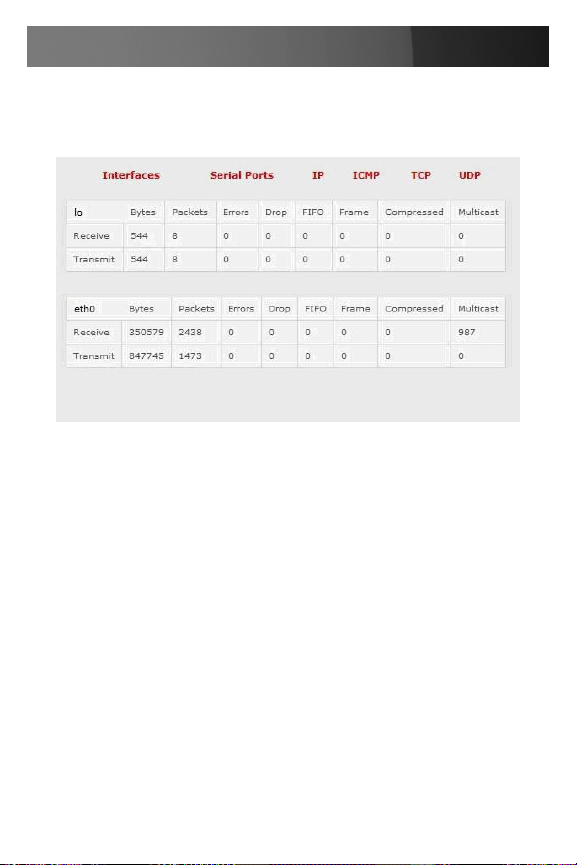
Instruction Manual
Statistics
The Statistics report provides a snapshot of the data traffic and other
activities and operations of your gateway.
Support Reports
The Support Report provides useful status information that will assist
the StarTech.com technical support team to solve any problems you may
experience with your ECS0016.
If you do experience a problem and have to contact support, you have the
option of including the Support Report with your email support request.
To generate a Support Report:
Select the 1. Status: Support Report menu option and you will be
presented with a snapshot of your gateway’s status.
Save the file as a text file (.txt) to an easily accessible location. 2.
86
Page 94
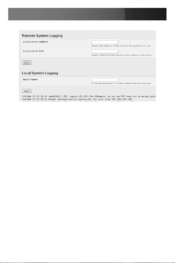
Instruction Manual
Syslog
The Linux System Logger maintains a record of all system messages and
errors. To view the System Log, select Status: Syslog
Remote System Logging: The syslog record can be redirected to a
remote Syslog Server. To do so, enter the remote Syslog Server address
and port details and click Apply Local System Logging
To view the local Syslog file:
Select Alerts & Logging: Syslog (To make it easier to find information in 1.
the local Syslog file, a pattern matching filter tool is provided).
Specify the Match Pattern for which you wish to search (e.g. the search 2.
for Mount is shown below) and click Apply. The Syslog will then be
represented with only those entries that actually include the specified
pattern
87
Page 95

Instruction Manual
Management
The ECS0016 has a number of Management reports and tools that can
be accessed by both Administrators and Users:
Access and control configured devices •
View serial port logs and host logs •
Use MetaConnect or the Java terminal to access serially attached •
consoles
Power control•
Device Management
To display all the connected Serial devices, Network Hosts and Power
devices, select Manage: Devices. By then selecting the Serial/ Network/
Power item, the display will be reduced to such devices only.
The user can take a range of actions on each of these Serial/Network/
Power devices by selecting the Action icon or related menu item.
Port Log Management
Administrator and Users can view logs of data transfers to connected
devices. To do so:
Select 1. Manage: Port Logs and the serial Port number to be displayed.
To display Host logs select 2. Manage: Host Logs and the Host to be
displayed
Power Management
Administrator and Users can access and manage the connected power
devices. To do so:
Select 1. Manage: Power.
88
Page 96

Instruction Manual
Serial Port Terminal Connection
Administrator and Users can communicate directly with the ECS0016
command line and with devices attached to the ECS0016 serial ports using MetaConnect and their local telnet client, or using a Java terminal in
their browser. To do so:
Select 1. Manage: Terminal
Click Connect to MetaConnect to access the ECS0016’s command line 2.
shell or the serial ports via MetaConnect. This will activate the
MetaConnect client on the computer you are browsing and load your
local telnet client to connect to the command line or serial port using
SSH.
Please Note that MetaConnect must be installed on the computer you
are browsing from and the ECS0016 must be added as a gateway.
89
Page 97

Instruction Manual
The alternate to using MetaConnect and your local telnet client is to
download the open source jcterm Java terminal applet into your browser
to connect to the ECS0016 and attached serial port devices. However
jcterm does have some JRE compatibility issues which may prevent it
from loading.
Select 1. Manage: Terminal. The jcterm Java applet is downloaded from
the ECS0016 to your browser and the virtual terminal will be displayed.
Select 2. File > Open SHELL Session from the jcterm menu to access
the command line using SSH
To access the ECS0016’s command line enter the gateway’s •
TCP address (e.g. 192.168.254.198) as hostname and the User
name (e.g. root@192.168.254.198, then enter the Password)
To access the ECS0016’s serial ports append :serial to the
username e.g. with the gateway’s TCP address (e.g.
192.168.254.198), the Username (e.g. root) enter
root:serial@192.168.254.198, then enter the Password and select
the TCP Port address for the serial port to be accessed. By default
3001 is selected (i.e. Port 1). To access Port 4 for example, this must
be changed to 3004 for the Username
Port Log Management
Administrator and Users can view logs of data transfers to connected
devices. To do so, Select Manage: Port Logs and the serial Port number
to be displayed.
To display Host logs, select Manage: Host Logs and the Host to be
displayed.
Basic Conguration - Linux Commands
For those who prefer to configure their ECS0016 at the Linux command
line level (rather than use a browser and the Management Console), this
chapter describes getting command line access and using the config tool
to manage the system and configure the ports etc. from the command
line:
Administration Configuration (System Settings and Authentication •
90
Page 98

Instruction Manual
Configuration)
Date and Time Configuration (Manually Change Clock Settings and •
Network Time Protocol Time Zone)
Network Configuration (Static and DHCP IP Configuration, Dial-in •
Configuration and Services Configuration)
Serial Port Configuration (Serial Port Settings, Supported Protocol •
Configuration, Users and Trusted Networks)
Event Logging Configuration (Remote Serial Port Log Storage and •
Alert Configuration)
The ECS0016 runs a standard Linux kernel so it is also possible to configure the gateway using other standard Linux and Busybox commands
and applications (ifconfig, gettyd, stty etc.) However doing this will not
guarantee these changes are permanent.
Please note: This chapter assumes you already have a certain level of
understanding before you execute Linux kernel level commands.
The Linux Command line
Power up the ECS0016 and connect the “terminal” device: 1.
If you are connecting using the serial line, plug a serial cable •
between the ECS0016 local DB9 port and terminal device. Configure
the serial connection of the “terminal” device/program you are using
to 115200bps, 8 data bits, no parity and one stop bit. If you are using
a program running on a Windows PC as the terminal device, then
the cable is made up from a Cat5 UTP (#440016) cable and two
DB9 to RJ45 adapters (#319000 and #319001)
If you are connecting over the LAN then you will need to •
interconnect the Ethernet ports and direct your terminal emulator
program to the IP address of the ECS0016 (192.168.0.1 by default)
Log on to the ECS0016 by pressing ‘return’ a few times. The ECS0016 2.
will request a username and password. Enter the username root and
the password default. You should now see the command line prompt
which is a hash (#)
91
Page 99

Instruction Manual
The config Tool:
Syntax
config [ ahv ] [ d id ] [ g id ] [ p path ] [ r configurator ] [ s id=value ]
Description
The config tool allows manipulation and querying of the system configuration from the command line. Using config, the new configuration can be
activated by running the relevant configurator which performs the action
necessary to make the configuration changes live.
Configuration elements which can be changed are specified by a unique
‘.’ separated name. For example the configuration file version is identified
as ‘config.version’.
Run all registered configurators. This
-a –run-all
-h –help
-v –verbose
-d –del=id
-g –get=id
-p –path=file
-r –run=configurator
-s --set=id=value
performs every configuration
synchronization action pushing all changes
to the live system
Display a brief usage message.
Log extra debug information
Remove the given configuration element
specified by a ‘.’ separated
identifier.
Display the value of a configuration element
Specify an alternate configuration file to
use. The default file is located at /etc/config/
config.xml
Run the specified registered configurator.
Registered configurators are alerts,
auth, dialin, eventlog, ipconfig, power,
serialconfig, services, systemsettings, time
and users.
Change the value of configuration element
specified by a ‘.’ separated identifier.
92
Page 100

Instruction Manual
The config tool is designed to perform multiple actions from one command if need be, so if necessary options can be chained together.
Options
Administration Configuration
System Settings
You can configure the system settings to the following values (denoted in
bolded text) using the corresponding commands from the command lines
(denoted by italicized text):
System Name og.mydomain.com
#/bin/cong–-set=cong.system.name=og.mydomain.com
System Password (root account) secret
#/bin/cong–-set=cong.system.password=secret
System SMTP Server 192.168.0.124
#/bin/cong–-set=cong.system.smtp.server=192.168.0.124
System SMTP Sender og@mydomain.com
#/bin/cong–-set=cong.system.smtp.sender=og@mydomain.com
The following command will synchronize the live system with the new
configuration.
#/bin/cong–-run=systemsettings
Authentication Configuration
You can configure the system remote authentication with the following
settings (denoted in bolded text):
Remote Authentication Method: LDAP
#/bin/cong–-set=cong.auth.type=LDAP
Server IP Address: 192.168.0.32
#/bin/cong–-set=cong.auth.server=192.168.0.32
Server Password: Secret
#/bin/cong–-set=cong.auth.password=Secret
93
 Loading...