

Page 1
Removable Drive Drawer for
3.5” IDE/ATA 133 Hard Drives
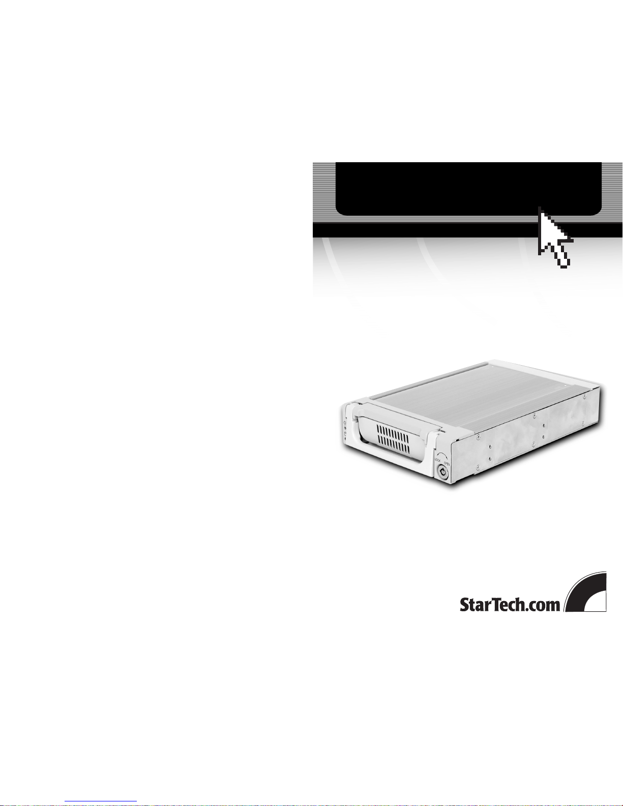
DRW150ATA
DRW150ATABK
Instruction Guide
The Professionals’ Source For Hard-to-Find Computer Parts
DRIV E DR AW ER
Revised: March 26, 2003
* DRW150ATAshown
* Actual product may vary from photo
Page 2

Technical Support
The following technical resources are available for this StarTech.com product:
On-line help:
We are constantly adding new information to the Tech Support section of our web site. To
access this page, click the Tech Support link on our homepage, www.startech.com. In the
tech support section there are a number of options that can provide assistance with this
card.
Knowledge Base - This tool allows you to search for answers to common issues using
key words that describe the product and your issue.
FAQ - This tool provides quick answers to the top questions asked by our customers.
Downloads - This selection takes you to our driver download page where you can
find the latest drivers for this product.
Call StarTech.com tech support for help: 1-519-455-4931
Support hours: Monday to Friday 9:00AM to 5:00PM EST (except holidays)
Warranty Information
This product is backed by a one-year warranty. In addition StarTech.com warrants its
products against defects in materials and workmanship for the periods noted below,
following the initial date of purchase. During this period, the products may be
returned for repair, or replacement with equivalent products at our discretion. The
warranty covers parts and labor costs only. StarTech.com does not warrant its products
from defects or damages arising from misuse, abuse, alteration, or normal wear and
tear.
Limitation of Liability
In no event shall the liability to StarTech.com Ltd. (or its officers, directors, employees or
agents) for any damages (whether direct or indirect, special, punitive incidental,
consequential, or otherwise), loss of profits, loss of business, or any pecuniary loss,
arising out of related to the use of the product exceed the actual price paid for
the product.
Some states do not allow the exclusion or limitation of incidental or consequential
damages. If such laws apply, the limitations or exclusions contained in this statement
may not apply to you.
7
Page 3

Table of Contents
Introduction . . . . . . . . . . . . . . . . . . . . . . . . . . . . . . . . . . . . . . . . . . . . . . . . . . . . . . . . 2
Installation . . . . . . . . . . . . . . . . . . . . . . . . . . . . . . . . . . . . . . . . . . . . . . . . . . . . . . . . . 3
Technical Specifications . . . . . . . . . . . . . . . . . . . . . . . . . . . . . . . . . . . . . . . . . . . . . . 6
Technical Support . . . . . . . . . . . . . . . . . . . . . . . . . . . . . . . . . . . . . . . . . . . . . . . . . . . 7
Warranty Information . . . . . . . . . . . . . . . . . . . . . . . . . . . . . . . . . . . . . . . . . . . . . . . 7
1
Technical Specifications
6
Drive connectors 40-pin IDE
Material Aluminum
Dimensions (LxWxH) 8.98 x 5.75 x 1.61 in. (228 x 146 x 41mm)
LEDs Power, HD access
Certifications CE
Page 4

Introduction
Thank you for purchasing a StarTech.com aluminum removable hard disk drawer. Now
you can quickly add and remove IDE/ATA 133 hard drives to your PC without having
to open your computer. Each unit consists of an outer bay that fits into any 5.25 inch
drive bay and a removable caddy that holds your hard disk. Whether for multiple
operating systems, making high speed, high capacity backups, or minimizing downtime
on mission-critical PCs, StarTech.com’s removable drive drawers provide the ultimate in
reliability and convenience.
Features
• Compatible with all 3.5” IDE/ATA133 hard drives
• Locking mechanism controls power to drive so that disk cannot be accidently
removed while operating
• Uses internal cableless IDE connector and adjustable power connector to ensure
compatibility with all hard drives
• LEDs keep you informed of drive power and activity status
• Swinging dust-resistant door helps keeps the inside of your computer clean
• Rear ball-bearing fan keeps hard drive running cool
• Backed by StarTech.com’s one-year warranty
Before You Begin
To ensure a quick and easy drawer installation, please read through this section carefully
before attempting to install the drawer.
WARNING! Hard drives, like all computer equipment, can be severely damaged by
static electricity. Be sure that you are properly grounded before opening your computer
case or touching your hard drive. StarTech.com recommends that you wear an anti-static
strap when installing any computer component. If an anti-static strap is unavailable,
discharge yourself of any static electricity build-up by touching a large grounded metal
surface (such as the computer case) for several seconds.
System Requirements
• An IBM-PC or Mac computer with an IDE hard drive interface
• One available 5.25” drive bay
• One drive connection cable
• One internal power cable
2
Monitoring Your Hard Disk Drive and Drawer
There are two LEDs located on the left side of the drive drawer. They are your best
indication of the hard drive’s status and activity.
• The top green LED indicates drive power. When the computer is turned on and the
drive has been locked in place, the green LED should be lit.
• The bottom yellow LED indicates hard drive activity. Do not attempt to unlock or
remove the drawer when this LED is lit. Attempting to remove the drawer while the
drive is in use may cause damage to your hard drive.
5
Page 5

3
Contents
This package should contain:
• 1 x drive caddy
• 1 x drive bay
• 2 x keys to lock/unlock the drive
• Assorted screws
Installation
NOTE: Before installing the drawer, you will have to determine if the drive you are
installing is a master or a slave. You should set the jumpers before installing the drive
into the drive drawer. Contact the hard drive manufacturer for more details.
If you are using two drives on the same IDE channel, make sure that one is set to Master
and the other is set to Slave. If you are only installing one drive on the channel, you
should configure it as a Master. Also make note of the configuration of all of your drives
so that you will not accidently assign two Masters or two Slaves to the same channel
when you are adding or removing hard drives later on.
Installing the Hard Drive in the Caddy
1. Remove the caddy from the bay by lifting the handle and sliding the caddy out of the
bay.
2. Remove the top panel from the caddy by sliding the lid towards the back of the
caddy. (It may help to press down on the lid near the front of the drawer and then
sliding the lid free.)
3. Gently place the hard drive in the caddy and position the drive so that it is firmly
connected to the IDE and power connectors at the back of the drawer. If necessary,
loosen the screw holding the power connector in place and adjust the connector left
or right to fit your hard drive.
4. Using the 6-32 x 1/4” (coarse thread) screws, secure your hard drive into the drawer.
5. Replace the top panel of the caddy.
Installing the Bay in the PC
1. Make sure your system is unplugged and you are grounded.
2. Remove the side covers from your system and remove the front cover from an
available 5 1/4” drive bay (see your computer’s user manual for details, if
necessary).
3. Insert the bay into the 5 1/4” bay slot, making sure that the screw-holes on the side
of the bay line up with the holes in the bay slot.
4. Connect your computer’s cable ribbon to the connector on the back of the bay.
5. Plug a connector from your computer’s power supply into the power port on the
back of the bay.
6. Using the M3 x 1/4” long (fine thread) screws, mount the bay into the PC.
Installing the Caddy in the Bay
1. With the handle lifted, slide the caddy into the bay until it is firmly seated. Lower the
handle to click the caddy into its proper position.
2. Insert the key and turn clockwise to lock the drive into place and supply the drive
with power. The drive will not function if the drawer has not been locked.
Removing the Drive Drawer
1. Insert the key and turn counter-clockwise to unlock the drive drawer.
2. Lift the handle and gently pull the caddy out of the bay.
NOTE: Do not unlock the drawer when the hard drive is in use (See “Monitoring Your
Hard Disk Drive and Drawer” on page 5). Only power down the drive when the hard
drive is idle. Once you have powered down the hard drive, wait about 15 seconds to let
the hard drive “spin down” before removing the caddy from the bay.
4
Caddy
Bay
5 1/4” Bay
Hard drive
Caddy
 Loading...