

Page 1
802.11g Wireless Router with
4-Port Switch
BR455GWDC
Instruction Guide
The Professionals’ Source For Hard-to-Find Computer Parts
WIRELESS RROUTER
* Actual product may vary from photo
Page 2

FCC COMPLIANCE STATEMENT
This equipment has been tested and found to comply with the limits for a Class B
digital device, pursuant to part 15 of the FCC Rules. These limits are designed to
provide reasonable protection against harmful interference in a residential installation.
This equipment generates, uses and can radiate radio frequency energy and, if not
installed and used in accordance with the instructions, may cause harmful interference
to radio communications. However, there is no guarantee that interference will not
occur in a particular installation. If this equipment does cause harmful interference to
radio or television reception, which can be determined by turning the equipment off
and on, the user is encouraged to try to correct the interference by one or more of the
following measures:
• Reorient or relocate the receiving antenna.
• Increase the separation between the equipment and receiver.
• Connect the equipment into an outlet on a circuit different from that to which the
receiver is connected.
• Consult the dealer or an experienced radio/TV technician for help.
Page 3

1
Table of Contents
Chapter 1: Introduction . . . . . . . . . . . . . . . . . . . . . . . . . . . . . . . . . . . . . . . . . . . . . . . . 3
Features . . . . . . . . . . . . . . . . . . . . . . . . . . . . . . . . . . . . . . . . . . . . . . . . . . . . . . . . . . 3
Before You Begin . . . . . . . . . . . . . . . . . . . . . . . . . . . . . . . . . . . . . . . . . . . . . . . . . . . 3
Minimum Requirements . . . . . . . . . . . . . . . . . . . . . . . . . . . . . . . . . . . . . . . . . . 3
Contents . . . . . . . . . . . . . . . . . . . . . . . . . . . . . . . . . . . . . . . . . . . . . . . . . . . . . . . 4
Router Basics . . . . . . . . . . . . . . . . . . . . . . . . . . . . . . . . . . . . . . . . . . . . . . . . . . . . . . 4
Back Panel . . . . . . . . . . . . . . . . . . . . . . . . . . . . . . . . . . . . . . . . . . . . . . . . . . . . . .4
Front Panel . . . . . . . . . . . . . . . . . . . . . . . . . . . . . . . . . . . . . . . . . . . . . . . . . . . . .5
Getting Started . . . . . . . . . . . . . . . . . . . . . . . . . . . . . . . . . . . . . . . . . . . . . . . . . . . . 6
Setting Up Your LAN . . . . . . . . . . . . . . . . . . . . . . . . . . . . . . . . . . . . . . . . . . . . 6
Configuring Your PCs . . . . . . . . . . . . . . . . . . . . . . . . . . . . . . . . . . . . . . . . . . . . 7
Accessing the Router Home Page . . . . . . . . . . . . . . . . . . . . . . . . . . . . . . . . . . . 9
Navigate the Router Management Interface . . . . . . . . . . . . . . . . . . . . . . . . . . 10
Chapter 2: Quick Setup . . . . . . . . . . . . . . . . . . . . . . . . . . . . . . . . . . . . . . . . . . . . . . . . 11
Time Zone . . . . . . . . . . . . . . . . . . . . . . . . . . . . . . . . . . . . . . . . . . . . . . . . . . . . . . . . 11
Broadband Type . . . . . . . . . . . . . . . . . . . . . . . . . . . . . . . . . . . . . . . . . . . . . . . . . . 12
Cable Modem . . . . . . . . . . . . . . . . . . . . . . . . . . . . . . . . . . . . . . . . . . . . . . . . . . 13
Fixed-IP xDSL . . . . . . . . . . . . . . . . . . . . . . . . . . . . . . . . . . . . . . . . . . . . . . . . . 14
PPPoE . . . . . . . . . . . . . . . . . . . . . . . . . . . . . . . . . . . . . . . . . . . . . . . . . . . . . . . 15
PPTP . . . . . . . . . . . . . . . . . . . . . . . . . . . . . . . . . . . . . . . . . . . . . . . . . . . . . . . . 16
Chapter 3: General Settings . . . . . . . . . . . . . . . . . . . . . . . . . . . . . . . . . . . . . . . . . . . . 17
System . . . . . . . . . . . . . . . . . . . . . . . . . . . . . . . . . . . . . . . . . . . . . . . . . . . . . . . . . . . 18
Time Zone . . . . . . . . . . . . . . . . . . . . . . . . . . . . . . . . . . . . . . . . . . . . . . . . . . . . 18
Password Settings . . . . . . . . . . . . . . . . . . . . . . . . . . . . . . . . . . . . . . . . . . . . . . 19
Remote Management . . . . . . . . . . . . . . . . . . . . . . . . . . . . . . . . . . . . . . . . . . . . 20
WAN . . . . . . . . . . . . . . . . . . . . . . . . . . . . . . . . . . . . . . . . . . . . . . . . . . . . . . . . . . . . 21
L2TP . . . . . . . . . . . . . . . . . . . . . . . . . . . . . . . . . . . . . . . . . . . . . . . . . . . . . . . . 22
Telstra . . . . . . . . . . . . . . . . . . . . . . . . . . . . . . . . . . . . . . . . . . . . . . . . . . . . . . . . 23
Bridge . . . . . . . . . . . . . . . . . . . . . . . . . . . . . . . . . . . . . . . . . . . . . . . . . . . . . . . . 24
DNS . . . . . . . . . . . . . . . . . . . . . . . . . . . . . . . . . . . . . . . . . . . . . . . . . . . . . . . . . 26
DDNS . . . . . . . . . . . . . . . . . . . . . . . . . . . . . . . . . . . . . . . . . . . . . . . . . . . . . . . 27
LAN . . . . . . . . . . . . . . . . . . . . . . . . . . . . . . . . . . . . . . . . . . . . . . . . . . . . . . . . . . . . . 28
Wireless . . . . . . . . . . . . . . . . . . . . . . . . . . . . . . . . . . . . . . . . . . . . . . . . . . . . . . . . . . 30
Basic Settings . . . . . . . . . . . . . . . . . . . . . . . . . . . . . . . . . . . . . . . . . . . . . . . . . 31
Wireless Advanced Settings . . . . . . . . . . . . . . . . . . . . . . . . . . . . . . . . . . . . . . 32
Encryption . . . . . . . . . . . . . . . . . . . . . . . . . . . . . . . . . . . . . . . . . . . . . . . . . . . . 33
NAT . . . . . . . . . . . . . . . . . . . . . . . . . . . . . . . . . . . . . . . . . . . . . . . . . . . . . . . . . . . . . 35
Port Forwarding . . . . . . . . . . . . . . . . . . . . . . . . . . . . . . . . . . . . . . . . . . . . . . . 36
Virtual Server . . . . . . . . . . . . . . . . . . . . . . . . . . . . . . . . . . . . . . . . . . . . . . . . . 37
Special Applications . . . . . . . . . . . . . . . . . . . . . . . . . . . . . . . . . . . . . . . . . . . . 39
ALG Settings . . . . . . . . . . . . . . . . . . . . . . . . . . . . . . . . . . . . . . . . . . . . . . . . . . 40
Page 4

2
Firewall . . . . . . . . . . . . . . . . . . . . . . . . . . . . . . . . . . . . . . . . . . . . . . . . . . . . . . . . . . 41
Access Control . . . . . . . . . . . . . . . . . . . . . . . . . . . . . . . . . . . . . . . . . . . . . . . . . 42
URL Blocking . . . . . . . . . . . . . . . . . . . . . . . . . . . . . . . . . . . . . . . . . . . . . . . . . 45
DoS . . . . . . . . . . . . . . . . . . . . . . . . . . . . . . . . . . . . . . . . . . . . . . . . . . . . . . . . . 46
DMZ . . . . . . . . . . . . . . . . . . . . . . . . . . . . . . . . . . . . . . . . . . . . . . . . . . . . . . . . 47
Chapter 4: Status . . . . . . . . . . . . . . . . . . . . . . . . . . . . . . . . . . . . . . . . . . . . . . . . . . . . . 48
Internet Connection . . . . . . . . . . . . . . . . . . . . . . . . . . . . . . . . . . . . . . . . . . . . . . . 49
Device Status . . . . . . . . . . . . . . . . . . . . . . . . . . . . . . . . . . . . . . . . . . . . . . . . . . . . . 50
Security Log . . . . . . . . . . . . . . . . . . . . . . . . . . . . . . . . . . . . . . . . . . . . . . . . . . . . . . 51
Active DHCP Client Table . . . . . . . . . . . . . . . . . . . . . . . . . . . . . . . . . . . . . . . . . . 52
Statistics . . . . . . . . . . . . . . . . . . . . . . . . . . . . . . . . . . . . . . . . . . . . . . . . . . . . . . . . . 53
Chapter 5: Tools . . . . . . . . . . . . . . . . . . . . . . . . . . . . . . . . . . . . . . . . . . . . . . . . . . . . . . 54
Configuration Tools . . . . . . . . . . . . . . . . . . . . . . . . . . . . . . . . . . . . . . . . . . . . . . . 55
Firmware Upgrade . . . . . . . . . . . . . . . . . . . . . . . . . . . . . . . . . . . . . . . . . . . . . . . . 56
Reset . . . . . . . . . . . . . . . . . . . . . . . . . . . . . . . . . . . . . . . . . . . . . . . . . . . . . . . . . . . . 57
Appendix A: IP Configuration Settings . . . . . . . . . . . . . . . . . . . . . . . . . . . . . . . . . 58
Appendix B: Popular Port Numbers . . . . . . . . . . . . . . . . . . . . . . . . . . . . . . . . . . . . 59
Appendix C: Setting a Static IP Address . . . . . . . . . . . . . . . . . . . . . . . . . . . . . . . . 60
Appendix D: Wireless Installation Considerations . . . . . . . . . . . . . . . . . . . . . . . 62
Troubleshooting . . . . . . . . . . . . . . . . . . . . . . . . . . . . . . . . . . . . . . . . . . . . . . . . . . . . . . 63
Glossary . . . . . . . . . . . . . . . . . . . . . . . . . . . . . . . . . . . . . . . . . . . . . . . . . . . . . . . . . . . . . 67
Technical Specifications . . . . . . . . . . . . . . . . . . . . . . . . . . . . . . . . . . . . . . . . . . . . . . . 72
Technical Support . . . . . . . . . . . . . . . . . . . . . . . . . . . . . . . . . . . . . . . . . . . . . . . . . . . . 73
Warranty Information . . . . . . . . . . . . . . . . . . . . . . . . . . . . . . . . . . . . . . . . . . . . . . . . . 73
Page 5

3
Chapter 1: Introduction
Thank you for purchasing a StarTech.com 802.11g wireless broadband router. Now you
can configure multiple users to share one high-speed xDSL or cable Internet connection.
The switch provides up to 54 Mbits/sec of wireless data transfer with 802.11g wireless
devices, and is backwards-compatible with 802.11b wireless devices. With the ability to
add hubs or switches to expand your network, this wireless router is ideal for small or
home offices (SOHOs) or medium-sized businesses.
Features
•Allows multiple users to share a single Internet line (cable or xDSL modem)
• Acts as an IEEE 802.11g wireless LAN access point for wireless communications
• Supports up to 253 wired and/or wireless users (through switches and hubs)
•Allows you to access private LAN servers from a public network
• Supports DHCP Server/Client for easy setup
• Supports advanced features such as: DMZ, Virtual Servers, Access Control, Firewall,
and Bridge Mode
• Allows you to monitor the router through DHCP Client Log, Security Log, and
Device/Connection Status
•Allows configuration and upgrades from remote site over the Internet
• Backed by StarTech.com’s two-year warranty
Before You Begin
To ensure a quick and easy router installation, please read through this section carefully
before attempting to install your router.
Note: Depending on your system and the firmware version you are running, the
instructions in this manual may not be identical to what you see on your screen.
Minimum Requirements
• An external xDSL or cable modem with an RJ-45 Ethernet port
• Each of the computers you want to network with the router must be equipped with a
network interface card (NIC) and a web browser (Internet Explorer 4.0 or higher, or
Netscape Navigator 4.7 or higher)
• StarTech.com does not provide Internet access with this product. Internet access must
be purchased separately through an Internet Service Provider.
Page 6
4
Contents
This package should contain:
•1 x four-port 802.11g broadband router unit
•1 x power adapter (12V DC 1A, Class 2 transformer)
Router Basics
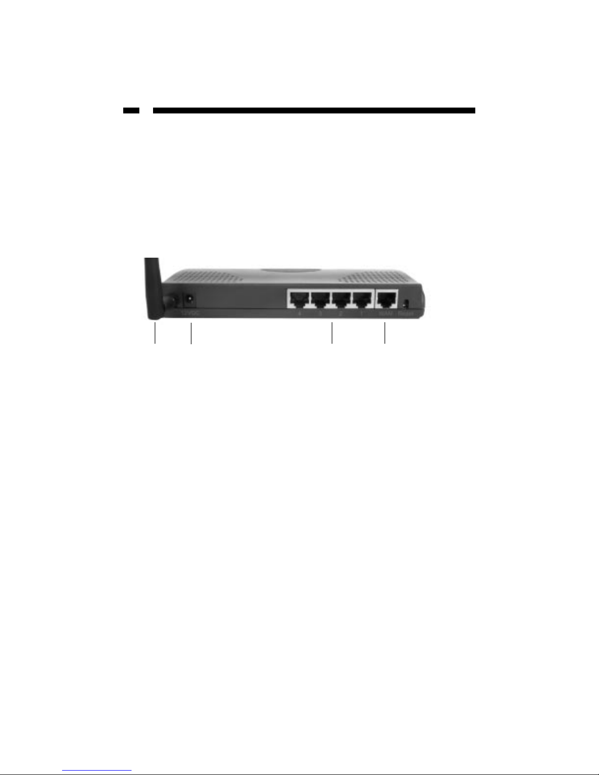
Back Panel
The back panel is divided into sections: Wireless, Power, LAN, WAN, and Reset.
• The wireless port is where you attach the wireless antenna.
• The 12VDC port is where you plug the power adapter.
• The four numbered Local Area Network (LAN) ports are where you connect your
wired LAN computers, print servers, hubs/switches, etc.
• The Wide Area Network (WAN) port is where you connect your cable/xDSL modem.
• The Reset button can be used to reboot the router if it is experiencing problems. If
you press and hold the reset button for less than four seconds, the router will reboot
with your settings and configurations intact. If you hold the reset button for more
than four seconds, the router will reset itself to the factory default settings and you
will lose all your settings and configurations.
Wireless Power LAN WAN
Page 7
5
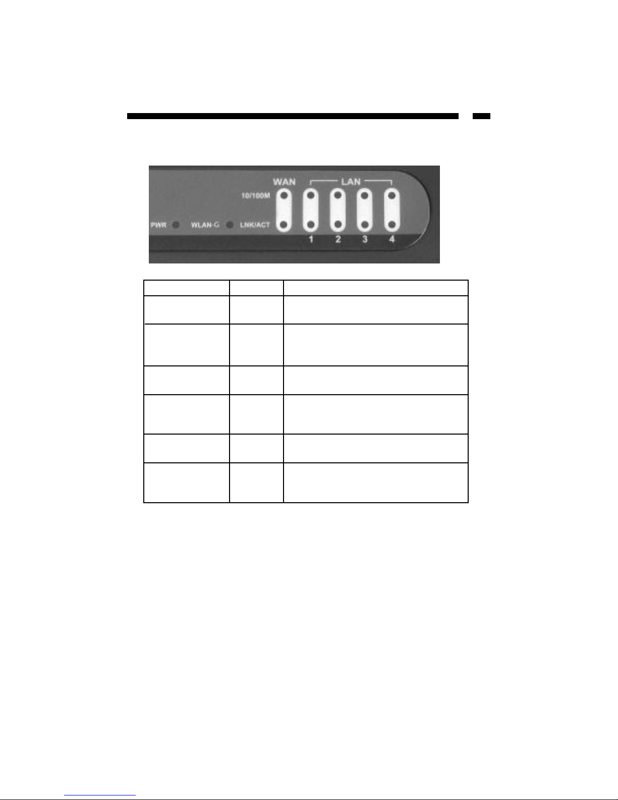
The Front Panel
The front panel LEDs are your best indication of the router’s activities.
LED Status Description
PWR On Router has power
Off Router has no power
WLAN-G On Wireless LAN is activated
Off Wireless LAN is disabled
Flashing Wireless LAN has activity, data being sent
WAN 10/100M On WAN port is connected at 100Mbits/sec
Off WAN port is connected at 10Mbits/sec
WAN LNK/ACT On WAN port is connected
Off WAN port has no connection
Flashing WAN port has activity, data being sent
LAN 10/100M On LAN port is connected at 100Mbits/sec
Off LAN port is connected at 10Mbits/sec
LAN LNK/ACT On LAN port is connected
Off LAN port has no connection
Flashing LAN port has activity, data being sent
Page 8
6
Getting Started
NOTE: The information in the following section as well as the information in Chapter 2:
Quick Setup is covered on the Quick Installation Guide that accompanies this manual. If
you have already performed the steps in the Quick Installation Guide, you can proceed
to Chapter 3: General Settings.
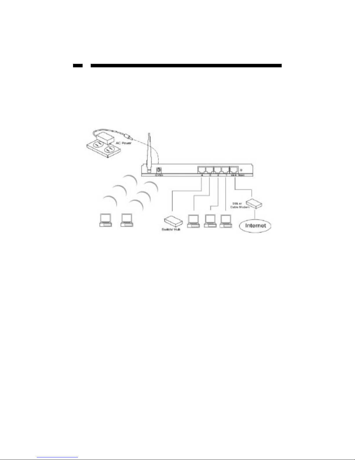
Setting Up Your LAN
1. Make sure all network devices are turned off.
2. Plug the power adapter into the 12VDC port on the back of the router. Plug the other
end into an available power source. The green PWR LED on the router should be lit.
3. Using an RJ-45 Ethernet cable, connect your modem to the router’s WAN port.
Connecting Your Wired Clients
Using RJ-45 Ethernet cables, connect your network devices to one of the four LAN
ports (labeled 1 through 4) on the back of the router.
Connecting Your Wireless Clients
The router also serves as a wireless access point (WAP) that allows you to wirelessly
connect your 802.11g or 802.11b-enabled computers to the router.
To connect your wireless devices to your router, make sure that your router is powered
and connected to your modem. From your wireless-enabled computer, use the
instructions provided by your wireless adapter manufacturer to connect the computer to
the router’s wireless access point.
The router’s default settings are:
ESSID: default
Channel: 1
Encryption Key: None
Sample Network
Page 9

7
Configuring Your PCs
Each of your PC clients must be set up to obtain IP addresses automatically.
NOTE: The instructions below are for Windows users only. If you are running an
operating system not listed below, make sure that you have installed a DHCP client
protocol. Consult your OS manufacturer for details, if necessary.
Windows XP
a. From your Control Panel, double-click the Network Connections icon.
b. Right-click on “Local Area Connection” and select Properties.
c. Select “Internet Protocol [TCP/IP]” and click the Properties button.
d. Select “Obtain an IP address automatically” and “Obtain DNS server address
automatically” and click OK.
Windows 2000
a. From your Control Panel, double-click on the Network and Dialup Connection icon.
b. Double-click the Local Area Connection icon.
c. Click the Properties button.
d. Check your “Network Components” list. You should see “Internet Protocol
[TCP/IP]”. Select it and click the Properties button.
e. Select “Obtain an IP address automatically” and “Obtain DNS server address
automatically” and click OK.
f. Reboot your PC. Your PC will now obtain an IP address automatically from your
router’s DHCP server.
Windows Me/98/95
a. Go to your Control Panel and double-click the Network icon.
b. Check the list of network components. If TCP/IP is not installed, click Add to install
it now. If TCP/IP is installed, go to step e.
c. In the “Network Component Type” box, select “Protocol” and click Add.
d. In the “Select Network Protocol” box, select “Microsoft” and “TCP/IP” and click OK.
You may need your Windows installation CD for this step.
e. After installing TCP/IP, go back to the Network dialog box. Select “TCP/IP” from the
list of network components and click Properties.
Page 10

8
f. Check each of the tabs and verify the following settings:
•Bindings: Check “Client for Microsoft Networks” and “File and printer sharing for
Microsoft Networks”
•Gateway: All fields are blank
• DNS Configuration: Select “Disable DNS”
•WINS Configuration: Select “Disable WINS Resolution”
•IPAddress: Select “Obtain IP address automatically”
g. Reboot your PC. Your PC will now obtain an IP address automatically from your
router’s DHCP server.
WinNT
a. Go to your Control Panel and double-click the Network icon. Select the Protocol tab.
b. Check the list of network components. If TCP/IP is not installed, click Add to install
it now. If TCP/IP is installed, go to step d.
c. In the “Select Network Protocol” window, select the “TCP/IP Protocol” and click OK
to start installing the protocol. You may need your Windows CD to complete this
installation.
d. Once TCP/IP is installed, go back to the “Network” window. Select “TCP/IP” from
the list of “Network Protocols” and click the Properties button.
e. Check each of the tabs and verify the following settings:
• IP Address: Select “Obtain an IP address from a DHCP server”
• DNS: All fields are blank
• WINS Address: All fields are blank
• Routing: All fields are blank
Page 11

9
Accessing the Router Home Page
Once your PCs have been properly configured, the router’s DHCP server will
automatically provide your LAN clients with an IP address.
NOTE: Please make sure that the DHCP server on the router is the only DHCP server
available on your LAN. If necessary, you can turn off the router’s DHCP server. See LAN
on page 28 for details.
1. On one of your PCs, open your web browser. In the address field, enter the router’s
default IP address (192.168.2.1) and press Enter.
NOTE: Your default home page may not load properly since the router has not been
configured. Enter the router’s IP address regardless of what appears on your screen.
2. Once the website has loaded, enter the User Name and Password and click OK. By
default, the User Name is admin and the password is 1234. You should change the
password as soon as possible (see Password Settings on page 19 for details). You will
now be on the router’s web-based management home page.
3. From the homepage, click on the Quick Setup Wizard link. The other sections
(General Setup, Status Information, and Tools) do NOT need to be configured to
access the Internet. For more information on these advanced features and settings, see
the appropriate section in the manual.
Page 12
10
Navigate the Router Management Interface
You can use the shortcut bar to move between pages when configuring the router.
When applicable, you can click on the question icon that appears to the right of the page
heading for a further definition or description of the information on the page.
Page 13
11
Chapter 2: Quick Setup
The Quick Setup feature will allow you to start sharing your Internet connection as
quickly as possible. Advanced features such as passwords or firewalls can not be
configured through Quick Setup.
BEFORE YOU BEGIN: Make sure that you know what type of Internet connection your
ISP uses: Cable Modem, Fixed-IP xDSL, Point-To-Point Protocol over Ethernet (PPPoE),
or Point-to-Point Tunneling Protocol (PPTP). Then see Broadband Type on page 12 to
find out the information that you will need to know about your specific connection.
Make sure that you have this information onhand prior to running Quick Setup. See
Appendix A for suggestions on how to find some of this information. Contact your
Internet Service Provider if you encounter difficulties finding this information.
From the router homepage, select Quick Setup.
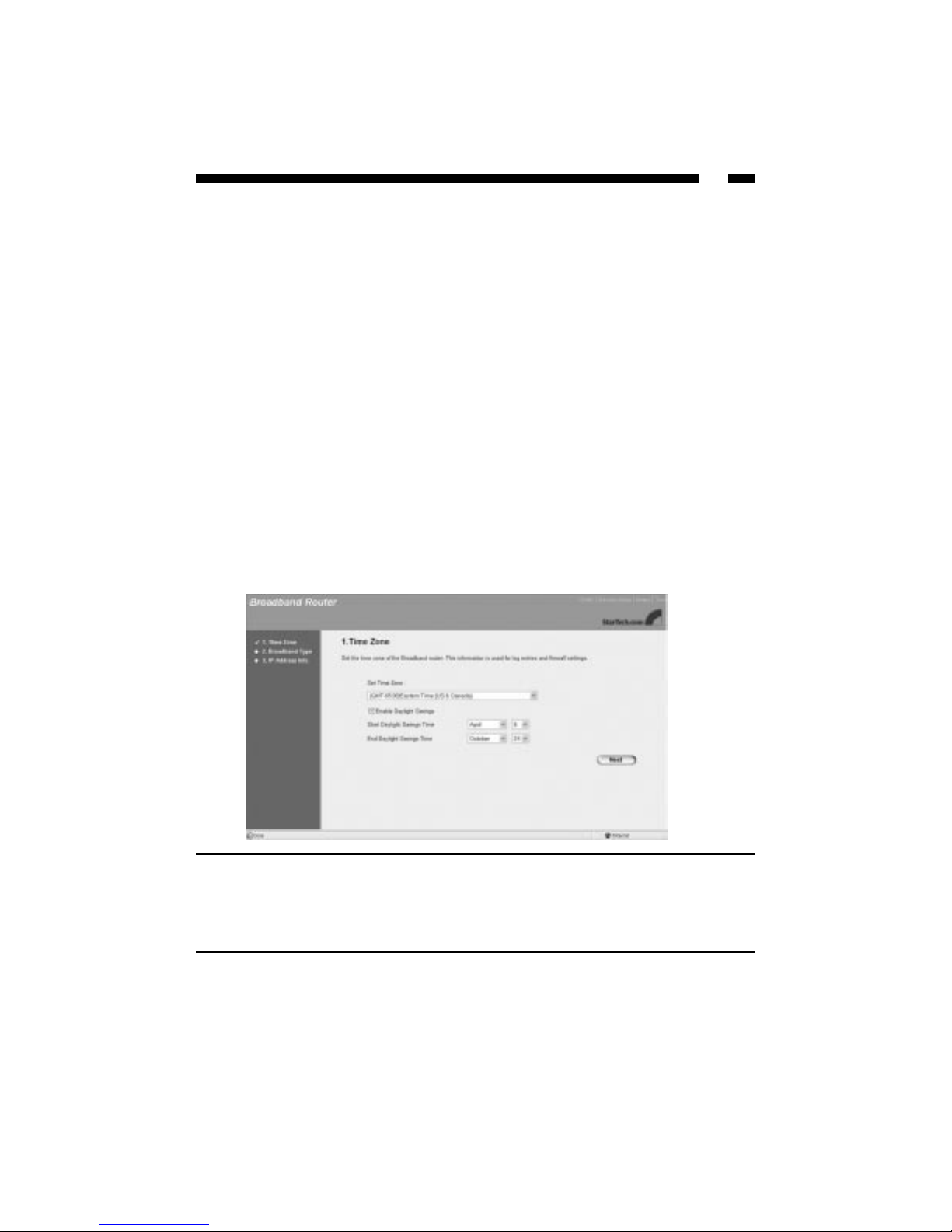
Time Zone
The Time Zone screen allows you to set the time zone you are operating in, as well as set
up daylight savings time (optional). The time zone information will affect router
functions such as log entries and firewall settings.
When you are satisfied with your Time Zone settings, click Next to proceed to the
Broadband Type page.
Parameter Description
Set Time Zone Select the time zone for the area you are in.
Daylight Savings To enable Daylight Savings, check the Enable
Daylight Savings box and enter the dates when
daylight savings begins and ends.
Page 14
12
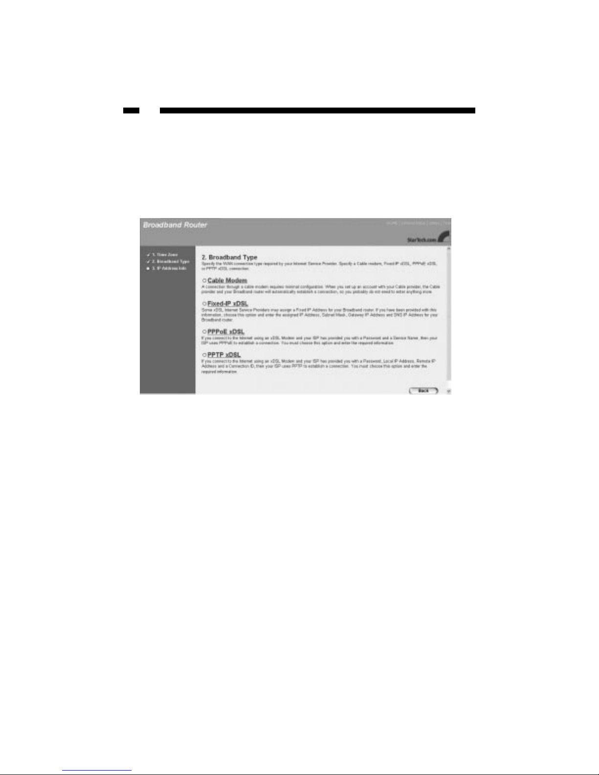
Broadband Type
The Broadband Type page requires you to select the method your ISP uses to connect
you to the Internet.
For tips on where to find the information required by the router, see Appendix A. If you
are unsure of what type of connection you are using or of where to find any of the
information required by the router, contact your ISP.
Select your connection type and proceed to the appropriate IP Address Info page.
Page 15
13
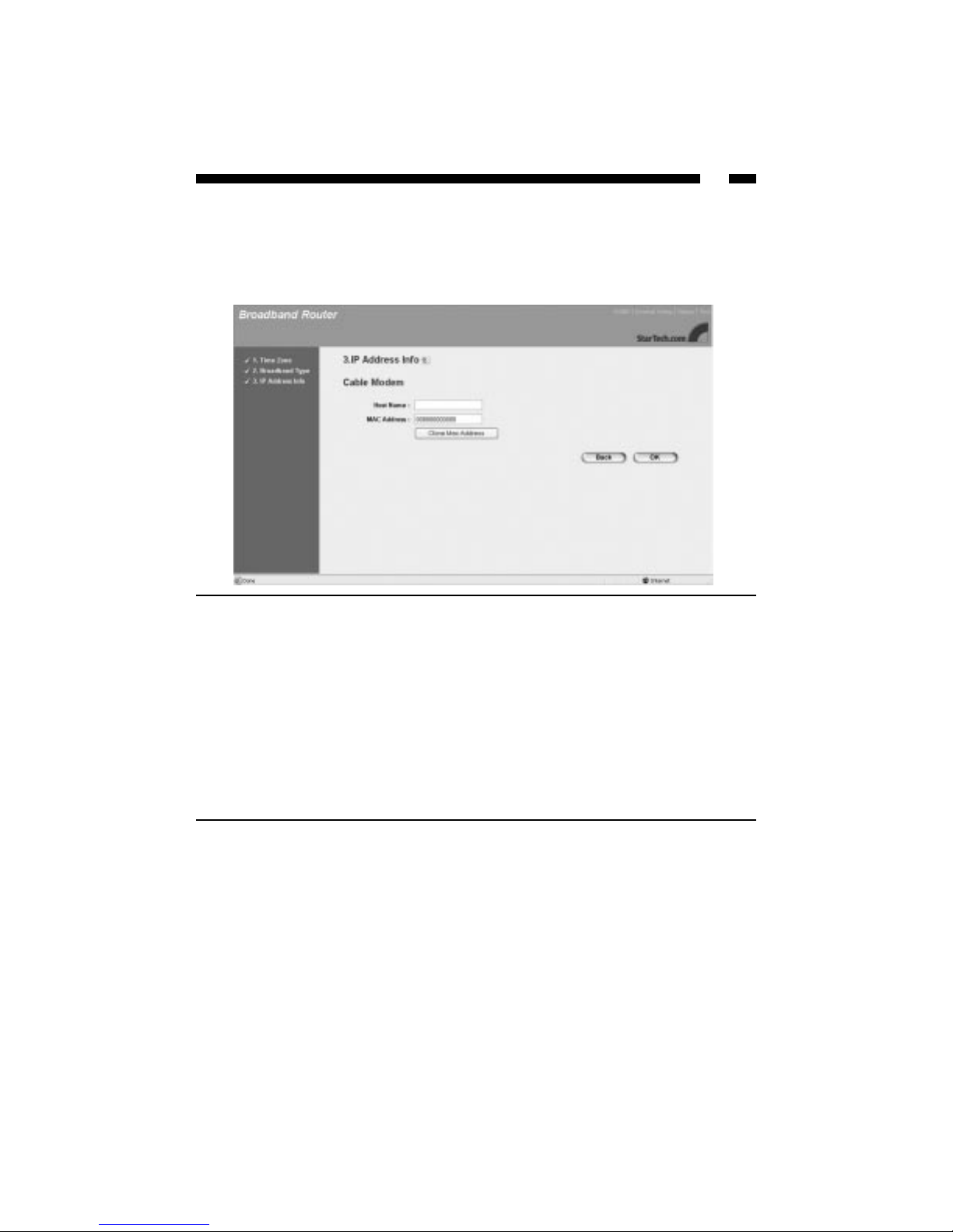
Cable Modem
If you are using a cable modem, your ISP will automatically provide you with an IP
address. Some ISPs may require that you fill in additional information, such as the Host
Name and MAC Address. If your ISP does not require this information, click OK to
complete the configuration.
When you are satisfied with your IP address settings, click the OK button.
Congratulations! You have completed the basic router configuration required for a Cable
Modem connection.
Parameter Description
Host Name Enter the Host Name (if required).
MAC Address Your ISP may be expecting the MAC address of the
adapter you were using when you initially signed
up with them. You can use the Clone button to copy
the MAC address from the adapter and apply it to
the router so that the ISP sees the MAC address it is
expecting when you connect to the Internet. (You
must be using the computer with the initial adapter
for this to work) You should record this information
so that you will not lose your ability to connect to
the Internet if you lose your settings or no longer
have the adapter.
Page 16
14
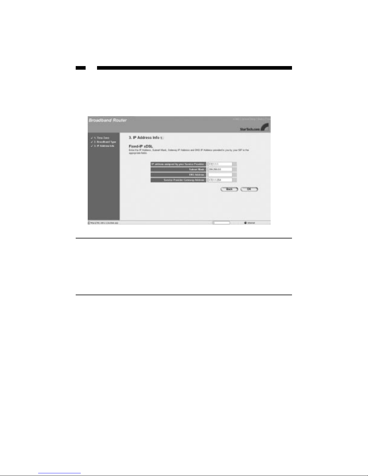
Fixed-IP xDSL
If you are using a Fixed-IP xDSL connection, your ISP has provided you with a specific
IP address for you to use. Your ISP can provide all the information required in this
section.
When you are satisfied with your IP address settings, click the OK button.
Congratulations! You have completed the basic router configuration required for a
Fixed-IP xDSL connection.
Parameter Description
IP address... Enter your IP address.
Subnet Mask Enter the subnet mask provided by your ISP.
DNS Address Enter your ISP’s DNS (Domain Name System)
server IP address.
Service Provider Gateway... Enter your ISP’s gateway IP address.
Page 17
15
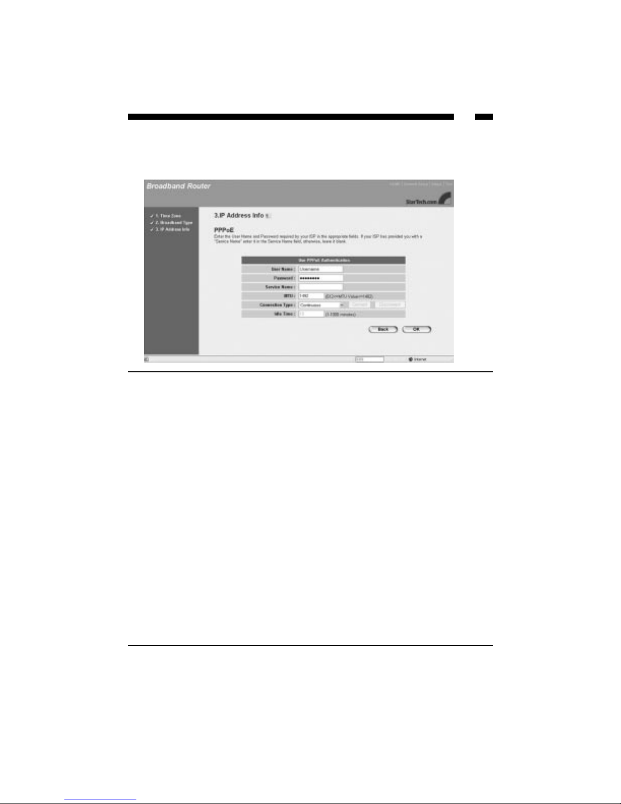
PPPoE
If your ISP uses the Point-to-Point over Ethernet (PPPoE) protocol to connect you to the
Internet, you will be required to fill in the information below.
When you are satisfied with your IP address settings, click the OK button.
Congratulations! You have completed the basic router configuration required for a
PPPoE connection.
Parameter Description
User Name Enter your user name.
Password Enter your password.
Service Name Enter the service name (if required).
MTU As an option, you can specify the maximum size of your
transmission packet to the Internet. Leave this field blank if
you do not wish to set a maximum packet size.
Connection Type Continuous: The router will always connect to the ISP. If the
WAN line breaks down and links again, the router will
automatically reconnect to the ISP.
Connect on Demand: The router will auto-connect to the ISP
when someone wants to use the Internet. The router will
close the connection if the period of inactivity lasts longer
than the specified Idle Time (see below).
Manual: The router will connect to the ISP only when you
click the Connect button on the web user interface. To end the
connection, click Disconnect. In this mode, Idle Time will not
affect the connection, nor will the router re-connect to the ISP
in case of a WAN line break.
Idle Time You can specify the idle time threshold (in minutes) for your
WAN port. If the time period expires with no Internet activity,
the router will automatically disconnect you from your ISP.
Page 18
16
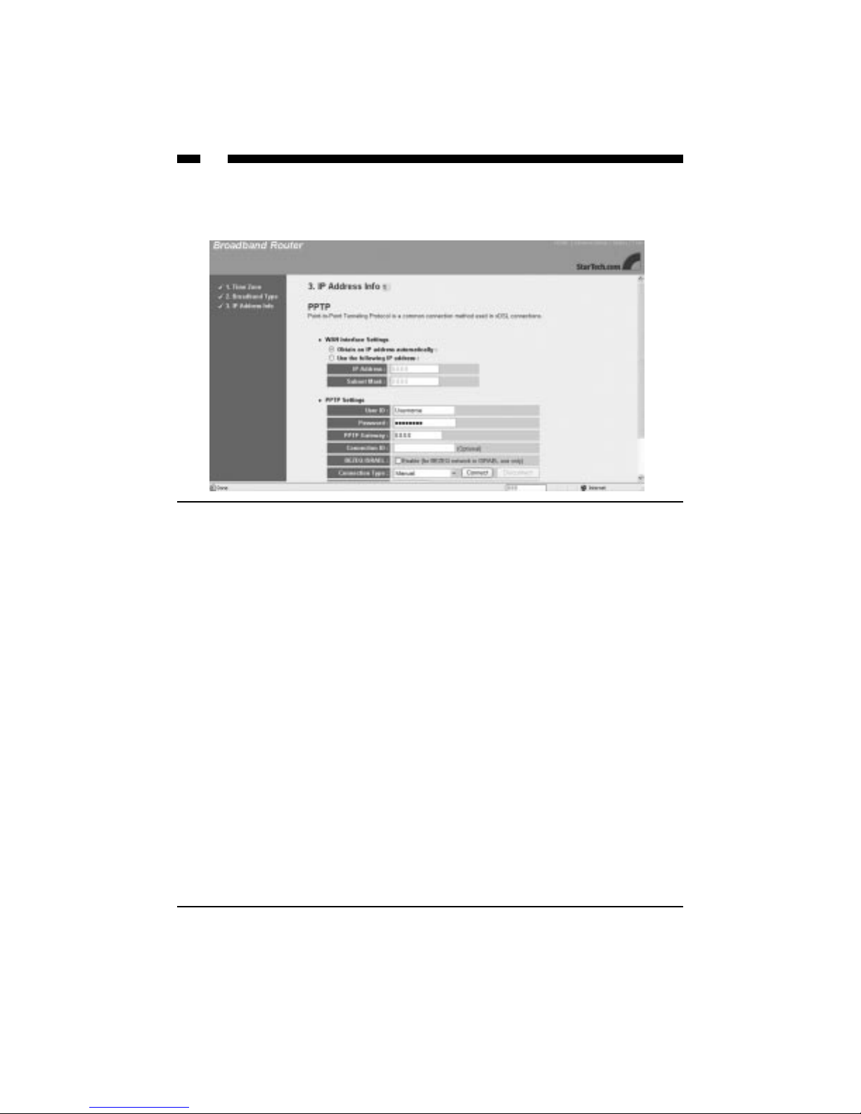
PPTP
If your ISP uses the Point-to-Point Tunneling Protocol (PPTP) to connect to the Internet,
you will be required to fill in the information below.
When you are satisfied with your IP address settings, click the OK button.
Congratulations! You have completed the basic router configuration required for a PPTP
connection.
Parameter Description
Obtain an IP... Check this box if your ISP assigns you an IP address by DHCP.
Use the following... Check this box if your ISP gives you a static IP address.
IP Address Enter the IP address assigned to you by the ISP.
Subnet Mask Enter the subnet mask provided by your ISP.
User ID Enter your User ID (also known as a connection ID).
Password Enter your password.
PPTP Gateway If your LAN has a PPTP gateway, enter the gateway IP address.
Connection ID This is the IP given by the ISP (optional).
BEZEQ-ISRAEL Check here if you are using BEZEQ service in Israel.
Connection Type Continuous: The router will always connect to the ISP. If the
WAN line breaks down and links again, the router will
automatically reconnect to the ISP.
Connect on Demand: The router will auto-connect to the ISP
when someone wants to use the Internet. The router will close
the connection if the period of inactivity lasts longer than the
specified Idle Time (see below).
Manual: The router will connect to the ISP only when you click
the Connect button on the web user interface. To end the
connection, click Disconnect. In this mode, Idle Time will not
affect the connection, nor will the router re-connect to the ISP in
case of a WAN line break.
Idle Time Out You can specify the idle time threshold (in minutes) for your
WAN port. If the time period expires with no Internet activity,
the router will automatically disconnect you from your ISP.
Page 19

17
Chapter 3: General Settings
The General Setup section contains advanced features that allow you to configure your
router to meet your network’s needs. From here you can: assign passwords, set up
remote management access, configure your LAN, WAN, and wireless settings, or set up a
firewall or DMZ, plus many other functions.
Remember, if you have already used the Quick Setup Wizard, you do not need to alter
any of the General Settings in order to share the Internet.
From the router homepage, click on General Setup.
You are given six options:
• System: Allows you to set the router’s time zone, password, and remote management
settings.
• WAN: Allows you to change your Internet connection type.
• LAN: Allows you to specify the LAN’s IP address and subnet mask, enable or disable
DHCP, and select an IP range for your LAN.
• Wireless: Allows you to configure and enable your wireless settings, including setting
up your ESSID, channel, and security settings.
• NAT:Allows you to configure the Port Forwarding, Virtual Server, and Special
Application settings to specify the users/packets that can pass through your router’s
NAT.
• Firewall: Allows you to configure access control, hacker prevention, and DMZ
settings.
Page 20

18
System
The System screen allows you to specify a time zone, change the system password, and
specify a remote management user for the router.
Time Zone
The Time Zone screen lets you specify the time zone you are in, as well as choose if and
when you want daylight savings enabled.
Parameter Description
Set Time Zone Select the time zone of the country you are in.
Time Server Address You can manually assign a time server IP address if the
default time server does not work.
Daylight Savings To enable Daylight Savings, check the Enable Function box
and enter the dates when daylight savings begins and ends.
Page 21
19
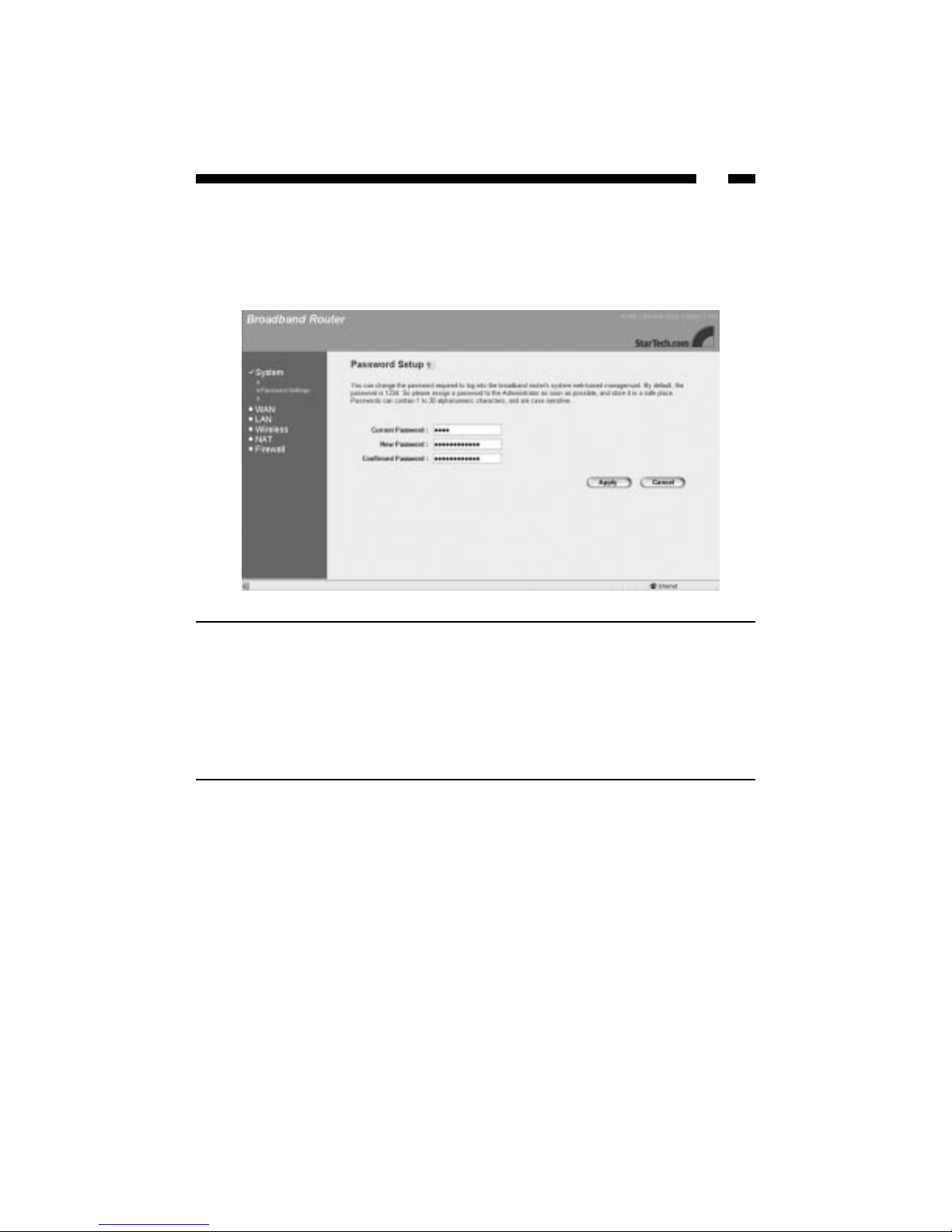
Password Settings
The Password Settings screen allows you to change the password required to access the
broadband router’s web-based management interface. By default password is 1234. It is
recommended that you assign a new password as soon as possible.
When you are satisfied with your password settings, click Apply.
Parameter Description
Current Password Enter your router’s current password. (By default
the password is 1234).
New Password Enter your new password.
Confirmed Password Enter your new password again for confirmation.
WARNING! If you forget your password, you will
have to reset the router, which will erase all of your
router configurations.
Page 22
20
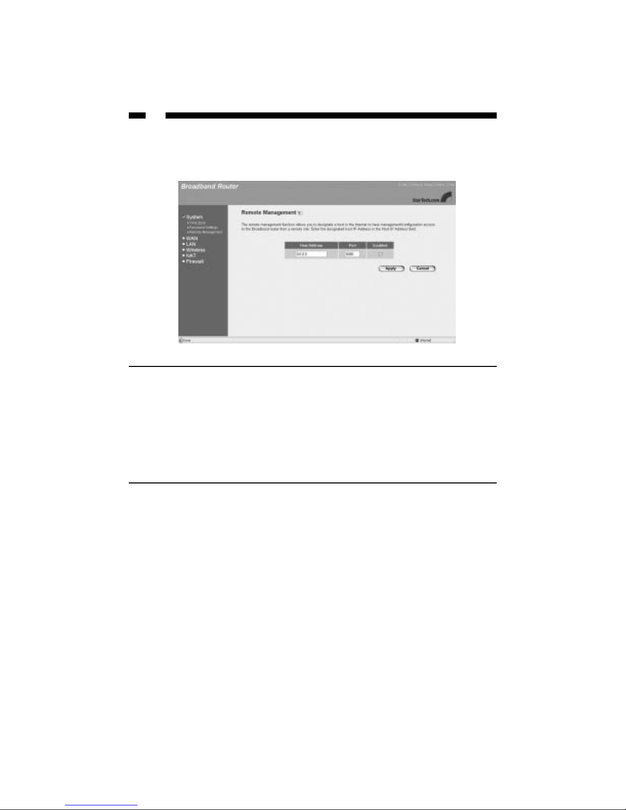
Remote Management
The remote management function allows you to designate an Internet host who can
access and configure the broadband router from a remote location.
NOTE: To access the web-based management interface from a remote site, enter the
wireless router’s WAN IP address followed by port number 8080 (i.e., 192.168.2.1\:8080).
The remote user will need to know the password, if applicable.
When you are satisfied with your remote management settings, click Apply.
Parameter Description
Host Address Check the Enabled box to allow Remote
Management. In the Host Address field, enter the IP
address of the host that will have remote
management/configuration access. The person at
this IP address will be able to configure and access
the router from their remote location.
If you enter a host address of 0.0.0.0 and check the
Enabled box, anyone can access and alter the router
configurations if they know the router password.
Page 23
21
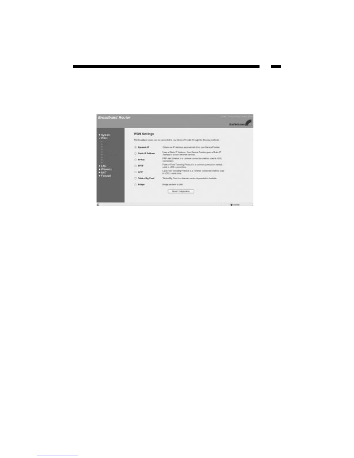
WAN
Most of the WAN settings are identical to the Broadband Type selection process you
went through in the Quick Setup Wizard.
To change your WAN connection to Cable Modem, PPPoE, PPTP, or Fixed-IP xDSL, turn
to Broadband Type on page 12.
Page 24

22
L2TP
You can choose Layer Two Tunneling Protocol (L2TP) if your ISP supports this protocol.
L2TP is an extension to the PPP protocol that allows the operation of Virtual Private
Networks (VPNs). Contact your ISP for details.
Parameter Description
Obtain an IP address... Check this box to obtain an IP address automatically.
Use the following... Check this box to use a specific IP address. In the fields
below, enter the IP Address, Subnet Mask, and Default
Gateway to use.
User ID Enter your L2TP user ID.
Password Enter your L2TP password.
L2TP Gateway Enter your L2TP default gateway.
Connection Type Continuous: The router will always connect to the ISP. If the
WAN line breaks down and links again, the router will
automatically reconnect to the ISP.
Connect on Demand: The router will auto-connect to the ISP
when someone wants to use the Internet. The router will
close the connection if the period of inactivity lasts longer
than the specified Idle Time (see below).
Manual: The router will connect to the ISP only when you
click the Connect button on the web user interface. To end
the connection, click Disconnect. In this mode, Idle Time will
not affect the connection, nor will the router re-connect to the
ISP in case of a WAN line break.
Idle Time Out You can specify the idle time threshold (in minutes) for your
WAN port. If the time period expires with no Internet
activity, the router will automatically disconnect you from
your ISP.
Page 25

23
Telstra
The Telstra page applies only to Telstra Big Pond users in Australia. For additional
information, contact Telstra.
Page 26

24
Bridge
From this screen you can set your broadband router to bridge mode and assign an IP
address for management purposes. When bridge mode is selected, the router essentially
connects and enables packet forwarding between homogenous networks. When the
router is in bridge mode, the original WAN MAC address is ignored and the original
LAN MAC address will be used as the MAC address. These values will be restored when
you set the device to any mode other than bridge mode.
When you are satisfied with your bridge mode settings, click Apply.
Parameter Description
IP Address Enter the IP address.
Subnet Mask Enter the subnet mask for bridge mode.
Page 27

25
Example: Bridge Mode
In this example of a bridged network, a computer on Network A is able to communicate
with a computer on Network B by sending a message to IP address 192.168.2.1, which in
turns sends a message to 172.25.3.14, which in turn sends the message to the computer
on Network B.
Page 28

26
DNS
If there is a Domain Name System (DNS) server that you would prefer to use instead of
the DNS server provided by your ISP, you can specify it here.
When you are satisfied with your DNS settings, click Apply.
Parameter Description
Domain Name Server (DNS) Enter the IP address of the DNS server you wish to
Address use. The default is your ISP’s DNS server.
Secondary DNS Address As an option, you can enter the IP address of a
second DNS server. If the primary DNSserver fails,
this secondary DNS server will be used.
Page 29

27
DDNS
DDNS (Dynamic DNS) lets you map your static domain name to a dynamic IP address.
You must have the account, password, and static domain name information from your
DDNS service provider to enable this feature. The router supports DynDNS and TZO.
When you are satisfied with your DDNS settings, click Apply.
Parameter Description
Dynamic DNS Choose whether to Enable or Disable DDNS. By
default, this feature is disabled.
Provider Select a DNS service provider. The default is
DynDNS.
Domain Name Enter the static domain name that uses DDNS.
Account/Email Enter the account assigned to you by your DDNS
provider.
Password/Key Enter the password for your DDNS account.
Page 30

28
LAN
The LAN port settings page allows you to specify a private IP address for your router’s
LAN port and specify a range of IP addresses for your DHCP server to issue to your
LAN clients.
Parameter Default Description
IP Address 192.168.2.1 This is the router’s LAN port IP address (the
default gateway address for each of your LAN
clients).
IP Subnet Mask 255.255.255.0 Enter the subnet mask for your LAN segment.
802.1d Spanning... Disabled When the 802.1d Spanning Tree function is enabled,
the router will use the spanning tree protocol to
prevent network loops from occurring in the LAN
ports.
DHCP Server Enabled With the DHCP server enabled, the router will
automatically give your LAN clients an IP address.
If this feature is disabled you will have to manually
set your LAN clients’ IP addresses. (Make sure that
your LAN client is in the same subnet as the router
if you want the router to be your LAN client’s
default gateway.)
Lease Time If you have enabled the DHCP server (see above),
the DHCP server will temporarily give your LAN
clients an IP address. If you specify a time period in
the Lease Time field, the DHCP server will refresh
your IP addresses once that time period has
expired.
Page 31

29
LAN continued
When you are satisfied with your LAN settings, click Apply.
Parameter Description
IP Address Pool Enter a Start IP and End IP address. Your DHCP
server will assign your LAN clients an IP address
from this pool. If you need to assign a static/fixed
IP address to one of your LAN PCs (i.e., for functions
like Virtual Server or DMZ), you will have to choose
an IP address from outside this pool.). The default
range is between 192.168.2.100 to 192.168.2.200.
Domain Name As an option, enter a Domain Name for your LAN.
Page 32

30
Wireless
The router also serves as a wireless access point, allowing you to wirelessly connect PCs
and laptops equipped with 802.11g or 802.11b adapters to your network. From the
Wireless screen, you can set your wireless ESSID and channel, set your wireless
encryption settings, and set your wireless access control parameters.
When you are satisfied with your wireless setting, click Apply. Click on one of the
wireless options on the left of the screen for more wireless settings.
Parameter Description
Enable or disable Wireless... Choose to enable or disable the wireless access
point module of the router. By default, the router ’s
wireless access point capabilities are enabled.
Page 33

31
Basic Settings
From the Basic Settings page you can set up the general parameters for your wireless
communications. You can also look up all associated wireless access stations (i.e., your
associated 802.11g-enabled client PCs) from this page.
When you are satisfied with your wireless settings, click Apply.
Parameter Default Description
Alias Name The alias name of the router
ESSID default Aname to identify the wireless portion of your
LAN. All wireless devices in your LAN must have
the same ESSID in order to communicate.
Channel Number 1 The channel used by the wireless LAN. All wireless
devices in your LAN must be on the same channel
in order to communicate.
Page 34

32
Wireless Advanced Settings
The Wireless Advanced Settings page lets you set some advanced wireless LAN
parameters. You should not change these parameters unless you know what effects they
will have on the router.
When you are satisfied with your advanced wireless settings, click Apply.
Parameter Description
Authentication Type Choose the type of authentication for your wireless LAN:
Open System: In Open System, wireless stations can associate
with the wireless router without any WEP encryption.
Shared Key: With Shared Key, only wireless clients with the
same WEP encryption key will be able to associate with the
router. In Shared Key mode, you will need to set up a WEP key
(See Encryption on page 33 for details).
Both: If you select Both, your wireless clients will be able to
associate with the wireless access point using either
authentication type.
Fragment Threshold Specifies the maximum packet size for data transmission. If
you set this value too low, it will result in bad performance.
RTS Threshold Specifies the RTS threshold for data transmission. When a data
packet is less than the specified RTS threshold, the wireless
router will not use the RTS/CT mechanism to send the packet.
Beacon Interval Specifies the amount of time between beacon broadcasts.
Preamble Type Defines the length of the CRC block in the frames during the
wireless transmission. “Short Preamble” is appropriate for high
traffic networks. “Long Preamble” provides more reliable
communication for less busy networks.
Page 35

33
Encryption
The Encryption page lets you set up security for your wireless network. If you set up an
encryption key, you must use the same key for both your wireless router and each of
your wireless clients.
If you select a 64-bit or 128-bit WEP key, you will need to enter the WEP key to encrypt
your data. See the next page for details.
Parameter Default Description
WEP Mode Disable If you enable WEP mode, you can choose either a
64-bit or 128-bit WEP key. The 128-bit key provides
greater security, but a lower throughput. If you
select Disable, your data will be transmitted
without encryption.
Page 36

34
Encryption continued
When you are satisfied with your encryption settings, click Apply.
Parameter Description
Key Format You can use either ASCII characters (alphanumeric
format) or hexadecimal digits (in the A~F, a~f, and
0~9 range) to be the WEP key. For example:
ASCII: guest
Hexadecimal: 12345abcde
Key Length Choose the length of your WEP encryption key.
Default Key Select one of the four encryption keys to encrypt
your data. Only the key you select in “Default Key”
will take effect.
Key 1 ~ Key 4 Fill in the text box using the rules below:
64-bit WEP: Input a ten-digit hexadecimal value
(example: 12345abcde) or a five-digit ASCII value
(example: guest).
128-bit WEP: Input a 26-digit hexadecimal value
(example: 0123456789abcdef0123456789) or a 13-
digit ASCII value (example: guestpassword).
Page 37

35
NAT
Network Address Translation (NAT) helps you conserve IP addresses by allowing
multiple local users to access the Internet through far fewer public IP addresses. NAT
also provides firewall protection from hacker attacks and allows you to map private IP
addresses to public IP addresses for key services such as websites or FTP.
Page 38

36
Port Forwarding
Port Forwarding allows you to re-direct a range of service port numbers (from the
Internet/WAN ports) to a particular LAN IP address. It helps you host some servers
behind the router’s NAT firewall.
Parameter Description
Enable Port Forwarding Check this box to allow port forwarding.
Private IP Enter the private IP address of the server behind the
firewall.
Type Select the protocol type to be forwarded. You can
choose TCP, UDP, or both.
Port Range Select the range of ports to be forwarded to the
private IP address. For information on port
numbers, see Appendix B.
Comment You can use this space to describe the setting.
Add, Reset When you have entered all the above information,
click the Add button to add the setting to the
Current Port Forwarding Table. To empty all fields,
click Reset.
Delete Selected, Delete All, To remove a setting, select it from the Current Port
Reset Forwarding Table and click Delete Selected. To
delete all settings, click Delete All. Click Reset to
clear your current selections.
Page 39

37
Virtual Server
Use the Virtual Server function when you want different servers/clients in your LAN to
handle specific applications (e.g., email, FTP, web server). Using different port numbers,
computers can recognize a particular application process or network service. The Virtual
Server function allows you to re-direct a remote request to a particular LAN private IP
address.
Parameter Description
Enable Virtual... Check this box to enable the virtual server.
Private IP Enter the private LAN client/host IP address that the packet will
be sent to. NOTE: You need to give the LAN PC clients a
fixed/static IP address outside the specified pool (see LAN on
page 28) for Virtual Server to work properly.
Private Port Enter the port number of the private client/host that the Public
Port will be mapped to.
Type Select the port’s protocol type (TCP or UDP). If you are unsure of
the type, leave it as the default TCP protocol.
Public Port Enter the service (Internet application) port number from the
Internet that will be re-directed to the above Private IP address
on your LAN.
Comment You can use this space to describe the setting.
Add, Reset When you have entered all the above information, click the Add
button to add the setting to the Virtual Server Table. To empty all
fields, click Reset.
Delete Selected, To remove a setting, select it from the Virtual Server Table and
Delete All, click Delete Selected. To delete all settings, click Delete All.
Reset Click Reset to clear your current selections.
Page 40

38
NOTE: The Virtual Server function has priority over the DMZ function (see DMZ on
page 47) if there is a conflict between the two.
Example: Virtual Server
The diagram below demonstrates one of the ways you can use the Virtual Server.
Private IP: 192.168.3.14
Private Port: 80 (HTTP)
Type: TCP
Public Port: 80 (HTTP)
In this example, the user wants the web server on their private LAN to be accessible to
Internet users. Any request from the Internet to access the web server is forwarded to the
LAN’s web server located at 192.168.3.14.
Page 41

39
Special Applications
Some applications (like Internet games, video conferencing, Internet telephony and
others) require multiple connections. The Special Applications function allows you to
configure the router to support multiple connections for these types of applications.
To run special applications, you need to know the port (outbound) information
associated with that application. In the example above, the rule states that when a user
triggers port number 2019, port numbers 2000-2038, 2050-2051, etc., are opened for access
to the ICU II application.
Parameter Description
Enable Trigger Port Check this box to enable the special applications function.
Trigger Port Enter the outgoing (Outbound) range of port numbers for
this particular application.
Trigger Type Select the Outbound port protocol: TCP, UDP, or both.
Public Port Enter the incoming (Inbound) port number for this type of
application. NOTE: Individual port numbers should be
separated by a comma. Use a hyphen to indicate a port
range (e.g. , 47624, 2300-2400).
Public Type Select the Inbound port protocol: TCP, UDP, or both.
Comment You can use this field to describe the setting.
Popular Applications This section lists some popular applications that require
multiple connections. Select an application from the list, and
click Add. If your application is not on the list, check with
the application manufacturer for the required port numbers.
Add, Reset When you have entered all the above information, click the
Add button to add the setting to the Current Trigger Port
Table. To empty all fields, click Reset.
Delete Selected, To remove a setting, select it from the Current Trigger Port
Delete All, Table and click Delete Selected. To delete all settings, click
Reset Delete All. Click Reset to clear your current selections.
Page 42

40
ALG Settings
An Application Layer Gateway (ALG) is an application-specific set of parameters to
control an application’s operations. An ALG manages specific protocols and lets the
application pass through the NAT gateway.
When you are satisfied with your ALG settings, click Apply.
Parameter Description
Enable Select which applications you are running that
require ALG. The router will let that application
pass through the NAT gateway.
Page 43

41
Firewall
To protect your network, the router comes equipped with extensive firewall protection.
From the Firewall screen, you can choose to specify which users can access certain
applications, block certain URLs, block common hacker attacks, and set up a DeMilitarized Zone (DMZ)
To enable your Firewall settings, make sure the Enable field is selected and click Apply.
Page 44

42
Access Control
The Access Control feature allows you to restrict users from accessing specific Internet
applications and services (e.g., email, FTP, Internet websites). You can also set time
restrictions on users and applications so that certain users can only access certain
applications during specified times.
There are two ways to set up access control: Filtering by IP or Filtering by MAC Address.
For information on Filtering by IP, see the table on the next page. For information on
Filtering by MAC Address, see the table below.
NOTE: If you enable MAC Filtering, only users with their MAC Addresses entered into
the table will have access to the network.
Parameter Description
Enable MAC Filtering Check this box to allow MAC filtering.
Client PC MAC Address Enter the MAC address of the PC that is allowed to
access the Internet
Comment You can use this space to describe the setting.
Add, Reset When you have entered all the above information,
click the Add button to add the setting to the
MAC Filtering Table. To empty all fields, click
Reset.
Delete Selected, Delete All, To remove a setting, select it from the MAC
Reset Filtering Table and click Delete Selected. To delete
all settings, click Delete All. Click Reset to clear
your current selections.
Page 45

43
Access control, continued
Filter Clients by IP
When you are satisfied with your Access Control settings, click Apply.
Parameter Description
Client PC Description The description of the Client PC rule.
Client PC IP Address Enter the IP address range that you want to apply the rule to.
If you are applying the rule to only one IP address, enter the
same address in both boxes.
NOTE: You need to give the LAN PC clients a fixed/static IP
address outside the specified pool (see LAN on page 28) for
Access Control to work properly.
Client Service Check off the services you want to block the user from
accessing.
Protocol Select the protocol type.
Port Range You can enter up to 5 port ranges that the clients will be
blocked from accessing.
Apply Changes, Reset When you are satisfied with your IP Filtering settings, click
Apply Changes. To clear all fields, click Reset.
Parameter Description
Add PC From the main Access Control page, click Add PC to bring
up the screen below.
Delete Selected, To remove a setting, select it from the IP Filtering Table and
Delete All click Delete Selected. To clear your settings, click Delete All.
Page 46

44
Example: Access Control
In the screen shot on the previous page, there is an access control restriction in place. The
computer with a fixed IP address of 192.168.3.14 has been blocked from accessing ports
1863 (MSN Messenger) and 5190 (AOL Instant Messenger).
Page 47

45
URL Blocking
You can block access to specific websites by entering either keywords or the website’s
URL.
When you are satisfied with your URL Blocking settings, click Apply.
Parameter Description
Enable URL Blocking Check this box to enable URL blocking.
URL/Keyword Type either the full URL or a keyword of the website you
want to block in this field.
Add, Reset When you have entered all the above information, click the
Add button to add the setting to the Current URL Blocking
Table. To empty all fields, click Reset.
Delete Selected, To remove a setting, select it from the Current URL Blocking
Delete All, Table and click Delete Selected. To delete all settings, click
Reset Delete All. Click Reset to clear all current selections.
Page 48

46
DoS
You can set up the firewall to block common hacker attacks, including DoS (Denial of
Service), Discard Ping from WAN, Port Scans, and Sync Floods.
When you are satisfied with your hacker prevention settings, click Apply.
Parameter Description
Ping of Death Check this box to protect your network from Ping of
Death attacks.
Discard Ping from WAN Check this box and the router’s WAN port will not
respond to any ping requests.
Port Scan Check this box to prevent others from scanning
your ports for weaknesses.
Sync Flood Check this box to prevent Sync Flood (or SYN
Flood) attacks.
Page 49

47
DMZ
If some of your PCs need to run Internet applications that are normally blocked by the
NATfirewall (i.e., online games), you can open those PCs up to unrestricted two-way
Internet access through a virtual DMZ host. DMZ lets you re-direct all packets going to
your WAN port IP address to a particular LAN IP address. While the Virtual Server
function lets you redirect specific services and applications (i.e., FTP, websites) to a
particular LAN client, a DMZ re-directs all packets (regardless of services) going to your
WANIPaddress to a particular LAN client/server.
When you are satisfied with your DMZ settings, click Apply.
Parameter Description
Enable DMZ Check this box to enable your DMZ.
NOTE: If there is a conflict between the Virtual
Server and DMZ settings, the Virtual Server will
have priority (see Virtual Server on page 37).
Public IP Address The public IP address of the WAN port or any
Public IP address given to you by your ISP.
Client PC IP Address Input the IP address of a particular host in your
LAN that will receive all the packets originally
going to the WAN port/Public IP address above.
NOTE: You need to give the LAN PC clients a
fixed/static IP address outside the specified pool
(see LAN on page 28) for Virtual Server to work
properly.
Page 50

48
Chapter 4: Status
The Status section allows you to monitor the status of your router. From the Status page
you can view your router’s system information, Internet connection status, configuration
settings, any illegal attempts to enter your network, and information on all DHCP client
PCs currently connected to the network.
From the router homepage, click on Status.
• Status and Information: The Status page gives you information about the router’s
hardware version, boot code version, and runtime code version.
You are also given four options:
• Internet Connection: The Internet Connection page gives you information on your
current Internet connection, WAN IP, subnet mask, Gateway, Primary DNS, and
Secondary DNS servers.
• Device Status: The Device Status page lets you view the router’s IP address, subnet
mask, DHCP server, and firewall settings.
• Security Log: The Security Log lists any illegal attempts to access your network.
• DHCP Client: The DHCP Client page gives you information on all the DHCP clients
currently linked to your router’s DHCP server.
Page 51

49
Internet Connection
You can view your current Internet connection status and related information.
Parameter Description
Attain IP Protocol Displays whether the router’s WAN port is
connected to a Cable/DSL modem.
IP Address Displays the router’s WAN IP address.
Subnet Mask Displays the router’s Subnet Mask.
Default Gateway Displays your gateway IP address.
MAC Address Displays the router’s MAC address.
Primary DNS Displays your primary Domain Name System
server ’s IP address.
Secondary DNS Displays your secondary DNS server ’s IP address, if
configured (See DNS on page 26).
Page 52

50
Device Status
The Device Status page shows you the router’s current configuration settings.
Parameter Description
ESSID Displays the WLAN’s ESSID.
Channel Number Displays the WLAN’s channel.
WEP Displays the WLAN’s security settings.
Associated Clients Displays the clients associated with the router.
IP Address Displays your router’s LAN IP address.
Subnet Mask Displays your router’s LAN subnet mask.
Default Gateway Displays the IP address of the default gateway.
DHCP Server Displays whether the router’s DHCP server is
enabled or disabled.
MAC Address Displays the MAC address of the router.
Page 53
51
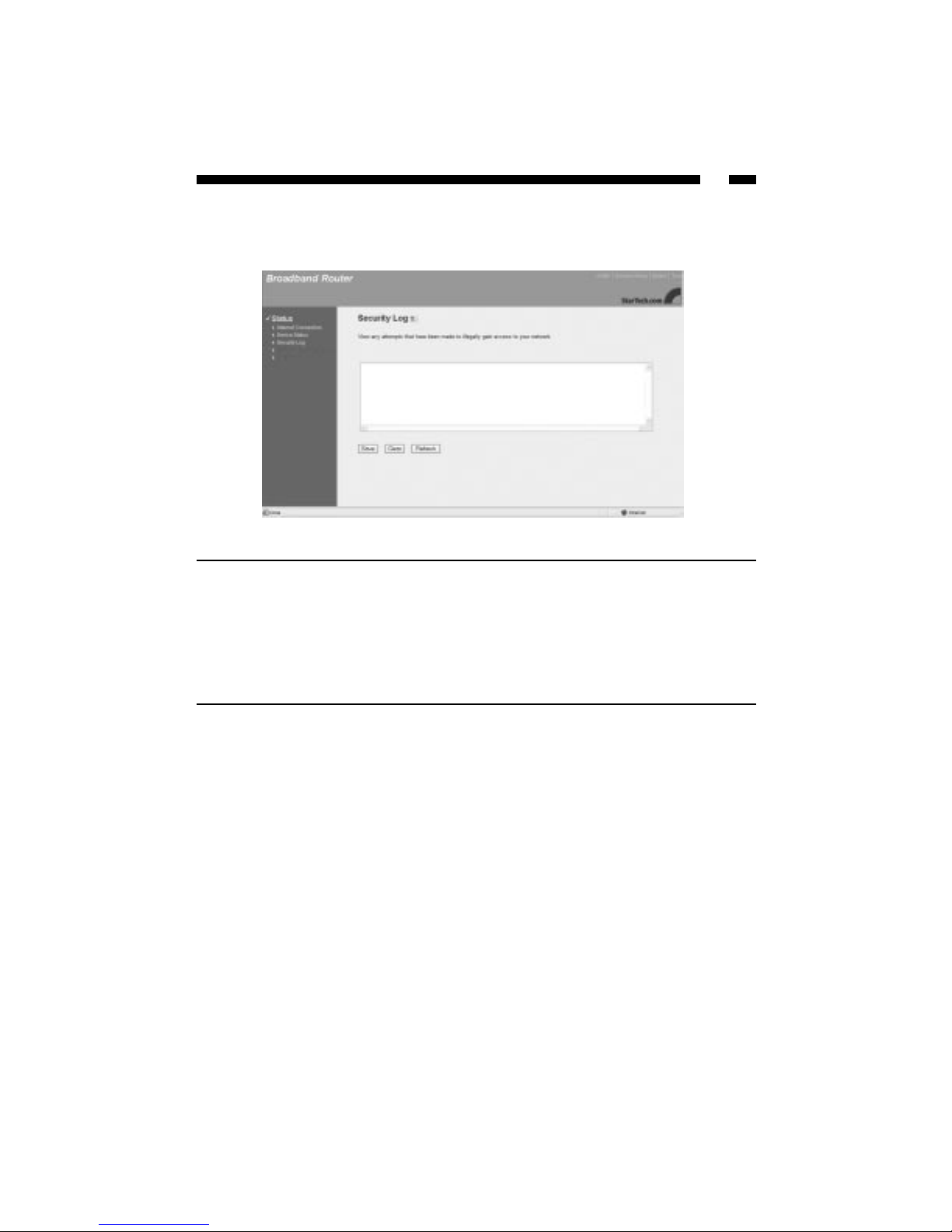
Security Log
This security log shows any attempts to gain illegal access to your network.
Parameter Description
Security Log The log lists information about all illegal attempts
to access your network. Click the Save button to
save the log to a local file for further processing.
Click Clear to clear the security log. Click Refresh
to get the most updated version of the log.
NOTE: When the system is powered down, the
security log will disappear if it has not been saved.
Page 54

52
Active DHCP Client Table
You can view information on the LAN clients that are currently linked to the router’s
DHCP server.
Parameter Description
DHCP Client Log This page shows all the DHCP LAN clients that are
currently connected to your network. The DHCP
client log displays the IP address, MAC address,
and time expired for each LAN client. Click the
Refresh button to get the most updated
information.
Page 55

53
Statistics
The Statistics page lets you see the number of packets sent and received on your Wireless
LAN, Ethernet LAN, and Ethernet WAN.
Click the Refresh button to get the most up-to-date information.
Page 56

54
Chapter 5: Tools
From the Tools page, you can save or restore configuration settings, upgrade the system
firmware, or reset the router.
From the wireless router homepage, click on Tools.
You have three options:
• Configuration Tools: You can save the router’s current configuration, restore the
router’s saved configuration files, or restore the router ’s factory default settings.
• Firmware Upgrade: You can upgrade the router’s firmware.
• Reset: You can reset the router in case of problems.
Page 57

55
Configuration Tools
The Configuration Tools page lets you save, restore, or reset your router’s configuration
settings.
Parameter Description
Backup Settings Clicking on the Save button will save the router ’s
current configuration to a file named “config.bin”.
Restore Settings Click on the Browse button to locate the file and
click Upload to re-load the saved configuration.
Restore to Factory Default Click Reset to force the router to do a power reset
that will clear all configurations and restore the
original factory default settings.
Page 58

56
Firmware Upgrade
StarTech.com may periodically offer firmware upgrades as a download on our website.
Visit www
.startech.com and click on the Downloads link to check for possible firmware
upgrades for this product. If there is an upgrade available, download the file according
to instructions on the website and then proceed with the following steps.
Parameter Description
Firmware Upgrade Browse to the location of the firmware upgrade and
click the Apply button. You may have to wait a few
minutes for the upgrade to complete.
Page 59

57
Reset
You can reset the router if you are experiencing any problems. Performing this step will
not change any of your current settings. If you want to reboot to the factory defaults, see
Configuration Tools on page 55.
Click on the Apply button to reset the router. You will be asked to confirm your decision.
The reset will be complete when the Power LED stops blinking. Once the reset process is
complete, you can start using the router again.
Page 60

58
Appendix A
Find and record your computer’s IP configuration settings
Note: The following instructions are valid for Windows 95/98/Me/2000/XP only. If you
are using a different OS, consult your OS manufacturer for details. If after completing
this procedure you are still unsure of where to find some of the required information,
contact your ISP for details.
1. Click on Start then Run.
2. Type “cmd” (or “command”) in the field and click OK.
3. At the command prompt, type “ipconfig /all” and press Enter. You should see a
screen with information similar to the following:
You should record the following information prior to connecting the router:
Host Name (if any):
MAC/Physical Address:
IP Address:
Subnet Mask:
Default Gateway:
Page 61

59
Appendix B
Popular Port Numbers
For online games, check with the game manufacturer for details on the specific ports or
port ranges need to be opened.
Note: The following list contains a selection of some of the most popular port numbers.
Amore complete list of port numbers is available on the Internet Assigned Numbers
Authority (IANA) website at: http://www
.iana.or
g/assignments/port-numbers.
Application Protocol Port Number
FTP TCP 21
Telnet TCP 23
SMTP TCP 25
HTTP TCP 80
POP3 TCP 110
SNMP UDP 161
SNMP Trap UDP 162
H.323 TCP 1720
PPTP TCP 1723
PC Anywhere TCP 5631
PC Anywhere UDP 5632
Page 62

Appendix C
Setting a Static IP Address
By default, the router uses its DHCP server to automatically assign your LAN clients a
dynamic IP address in the range of 192.168.2.100 to 192.168.2.199 (You can edit this range.
See LAN on page 28 for details). To use certain router functions such as address mapping
or virtual server, you may need to assign a PC a static/fixed IP address. Remember that
each PC that uses TCP/IP must be identified through a unique IP address in the network
and that the address you choose is outside the range listed above. If the IP address you
choose is not unique to the network, Windows will generate an IP conflict error message.
If your OS is not listed below, consult your OS manufacturer for details on performing
this procedure.
Windows XP/2000
Note: These instructions assume that Windows XP users are using “Classic View”.
1. From your Control Panel, double-click on Network and Dial-Up Connections
(Windows 2000) or Network Connections (Windows XP).
2. Right-click on the Local Area Connection and select Properties.
3. In the “Components checked are used by this connection” box, select Internet
Protocol (TCP/IP), and click the Properties button.
4. Select “Use the following IP address”. Enter a unique IP address that is not used by
any other computer on the network connected to the router. Make sure that each IP
address is unique for each PC or network device. Make sure that the IP address you
select is NOT in the range specified for the router’s DHCP server.
5. Enter “255.255.255.0” as the Subnet Mask.
6. Enter 192.168.2.1 (the router’s default IP address) as the default gateway.
7. Toward the bottom of the window, select “Use the following DNS server addresses”
and enter the Preferred DNS server and Alternative DNS server (provided by your
ISP). Contact your ISP for information.
8. Click OK and restart the computer to allow the changes to take effect.
60
Page 63

61
Windows Me/98/95
1. From your Control Panel, double-click on the Network icon.
2. Under the Protocols tab, highlight TCP/IP and click the Properties button.
3. Select the IP address tab, and select “Specify an IP address”. Enter a unique IP
address that is not used by any other computer on the network connected to the
router. Make sure that each IP address is unique for each PC or network device. Make
sure that the IP address you select is NOT in the range specified for the router ’s
DHCP server.
4. Click the Gateway tab and enter 192.168.2.1 (the router’s default IP address) in the
“New Gateway” field. Click Add.
5. Click the “DNS Configuration” tab and make sure the “Enable DNS” option is
selected. Enter the Host and Domain names. Enter the IP address of your ISP’s DNS
server. Contact your ISP if you can not find this information.
6. Click OK and restart your computer to allow the changes to take effect.
Windows NT 4.0
1. From your Control Panel, double-click on Network.
2. Click the Protocol tab, and highlight TCP/IP and click “Properties”.
3. Enter a unique IP address that is not used by any other computer on the network
connected to the router. Make sure that each IP address is unique for each PC or
network device. Make sure that the IP address you select is NOT in the range
specified for the router’s DHCP server.
4. Enter “255.255.255.0” as the Subnet Mask.
5. Enter 192.168.2.1 (the router’s default IP address) as the default gateway.
6. Click the DNS tab and enter the Host and Domain names. Enter the IP address of
your ISP’s DNS server. Contact your ISP if you can not find this information.
7. Click OK and restart the computer if asked.
Page 64

62
Appendix D: Wireless Installation Considerations
The BR455GWDC lets you use your desktop computer to access your WLAN, but there
are some things to keep in mind when attempting to set up a wireless connection. The
wireless signal range can be limited by the number, location, thickness, and material of
ceilings, walls or similar that the signal must pass through. To maximize your wireless
range, keep the following considerations in mind when positioning your antenna:
•Try to minimize the number of walls, ceilings, and similar between your wireless
devices. Each wall or ceiling the signal must cross can reduce the signal range by
up to 90 feet (30 m). Position your receiving devices so that the path between them is
as unobstructed as possible.
• The type of material the wireless signal must cross through also affects its range. A
solid metal door or concrete wall can decrease the signal’s range. Whenever possible,
position the adapters so that the signal can pass between drywall or open doors.
• Make sure that you are aware of the line the signal must take to travel between
devices. The angle that the signal is on as it travels through a door, wall, or ceiling
affects how thick the obstruction is. For example, if a wall is 1.5 feet thick and the
signal passes through it at a 45-degree angle, the signal must pass through 3 feet (1m)
of wall. At a 2-degree angle, the wall appears to be 42 feet (14m) thick. Always try to
position your devices so that the signal can travel at 90-degree angles.
• Electrical devices or appliances that generate RF noise (such as microwaves, electric
motors or computer monitors) can interfere with the wireless signal. Try to keep your
adapter at least 3-6 feet (1-2 m) away from these types of devices.
Page 65

63
Troubleshooting
If you are experiencing connection difficulties, first check your cables:
• Make sure that all cables are in their proper ports and firmly seated.
• Make sure that cables connected to PCs/LAN clients are not plugged into the WAN
port and that the cable from the modem is plugged into the WAN port.
•Check to see if your power supply is plugged into a functioning power source and
that your Power LED is on.
•Avoid interference. Network cabling can be run under floors, around office dividers,
or over dropped ceilings. When planning your wiring layout, try to keep cables away
from power outlets, florescent lighting fixtures, uninterruptible power supplies, and
other sources of strong electromagnetic interference.
• Some modems may require the use of a cross-over cable. Check with your modem
manufacturer for details.
If you are having trouble with your wireless connections, check the following:
• Make sure all your wireless clients are equipped with 802.11g-compatible wireless
adapters.
• Make sure that your wireless router and all your wireless clients have the same ESSID
and are on the same channel.
• If you have enabled encryption options, make sure that the same encryption key has
been entered on each device. Make sure that the key selected on your wireless router
is the same key entered on the other wireless device you want to connect to.
• If you are experiencing intermittent network connections, try re-orienting the adapter.
See Appendix D: Installation Considerations for more details.
Make sure you have entered the proper configuration information.
• Reread the instructions on the Quick Install page and in Chapters 1 and 2. Make sure
you have completed all steps.
• Make sure that you have selected the proper Internet connection type and have
entered all the required information about your computer’s IP configuration. Ask
your ISP if you have any difficulties finding the required information.
• Some ISPs may bind your Internet connection to the MAC address of your PC’s NIC.
You may be required to clone this MAC address. See Broadband Type on page 12
for details.
Page 66

64
Make sure that each PC connected to the router has a functioning NIC and you are
using a functioning modem.
• Plug your cable or DSL modem directly into the RJ-45 port on your PC's network
adapter, without using your router. If your Internet connection is still not up, then it
is likely that your PC's network card is not functional. Remember, the router does
not replace a modem. The router works in conjunction with a cable or DSL modem.
The router alone will not provide you with Internet access.
Test your Internet connection.
You can try to pin down the location of the problem by completing the following steps:
• Ping your router.
1. Click on Start then Run.
2. Type “cmd”(or “command”) in the field and click Run.
3. Type “ping 192.168.2.1” (the router’s default IP address) and press Enter.
If you see four “Reply from 192.168.2.1” messages, the connection is successful.
If you see four “Request timed out” or “Destination host unreachable” messages,
there is a problem with your router connection. This is likely a hardware problem.
Check your cables, NICs, and router.
• Ping an outside IP address.
1. Click on Start then Run.
2. Type “cmd” (or “command”) in the field and click Run.
3. Type “ping xx.xx.xx.xx” (where xx.xx.xx.xx is the IP address of computer that is
outside your network) and press Enter.
If you were able to successfully ping your router, but are not able to ping an IP
address outside the router, the problem likely lies with the router. Please contact
StarTech.com technical support.
• Ping an outside website.
1. Click on Start then Run.
2. Type “cmd” (or “command”) in the field and click Run.
3. Type “ping <web address>”. Make sure you enter a valid web address after you
type “ping”. Press Enter.
Note that some websites may have firewalls that will not respond to ping
requests. Be sure to try a few different web sites. If you are unable to ping an
outside web address, there is possibly a DNS error on the PC. See “Configuring
Your PCs” on page 7.
Page 67

65
If problems persist, try resetting the router.
•Press the router's reset button with a pencil tip for less than 4 seconds and the router
will re-boot itself, keeping your original configurations. If problems persist or you
experience extreme problems, press the reset button for longer than 4 seconds and the
router will reset itself to the factory default settings. Warning: This procedure will
erase all your configurations and replace them with the factory default settings.
Online Gaming Problems
• Some online games require certain ports to be opened in order to function properly.
See Special Applications on page 39 in the manual for details on how to open
ports. Check with the game manufacturer’s technical support for details on which
specific ports need to be opened.
• Multiple gamers on the LAN may not be able to get on a game server and play
simultaneously with only one public IP. Check with the game's technical support for
details on whether they support multi-login on one IP address.
Forgotten Password
• If you have forgotten your password, you have to reset the router. Press the reset
button for more than 4 seconds and the router will reset itself to the factory default
settings. All your configurations will be replaced with the factory default settings.
Remove your proxy settings
PPPoE users may need to disable the proxy settings or the dial-up popup window. Since
the router is the gateway for the Internet connection, your computer does not need proxy
settings to gain access. Follow the directions below to verify that you do not have any
proxy settings and that your browser is set to connect directly to the LAN.
• Microsoft Internet Explorer 5.0 or higher:
1. From your PC’s Control Panel, click on Internet Options.
2. Click the Connections tab.
3. Click on the LAN settings button and make sure no boxes are checked.
4. Click the OK button to go back to the previous screen.
5. Make sure “Never dial a connection” is checked. This will remove any dial-up
pop-ups for PPPoE users.
6. Click OK to close the Internet Options window.
Page 68

66
• For Netscape Navigator 4.7 or higher:
1. Start Netscape Navigator.
2. From the Edit menu, click Preferences.
3. Expand the Advanced list by clicking on the “+” sign and click Proxies.
4. Make sure “Direct connection to the Internet” is selected.
5. Close all windows to finish.
Page 69

67
Glossary
802.11b: Afamily of IEEE-defined specifications for wireless networks. The 802.11b
standard supports data transfer rates up to 11 Mbits/sec in the 2.4 GHz band using DSSS
technology. Also known as WiFi.
802.11g: Afamily of IEEE-defined specifications for wireless networks. The 802.11g
standard supports data transfer rates up to 54 Mbits/sec in the 2.4 GHz band using DSSS
technology. Also backwards compatible with 802.11b.
Access Point: See Wireless Access Point.
Ad Hoc: A wireless computer-to-computer LAN. An Ad Hoc network can consist of two
devices with wireless adapters, and does not require a WAP, router, or gateway. Also
known as peer-to-peer mode. See also infrastructure.
ALG (Application Layer Gateway): Astricter security policy for specific applications. A
special code (known as a proxy server) is installed to control the flow of Internet services
through the firewall to the application.
Associated Client: See Client PC.
Beacon: A packet that identifies the location of the base wireless station and allows the
mobile clients to synchronize with the base station.
Bridge: An intelligent, internetworking device that forwards or filters packets between
different networks based on data link layer (MAC) address information.
Broadband: A method of communication where a wide band of frequencies is available
to transmit voice, data, and video signals over a single medium. Information can be sent
on many different channels, allowing more information to be sent in a given period of
time (the same way multiple lanes allow more cars on the road).
BSSID (Basic Service Set Identifier): The MAC address of the wireless router. A BSS
consists of a Wireless Access Point and the adapters associated with it.
Cable Modem: A device that provides Internet access to a user by connecting a computer
to the cable television network, which in turn connects to the Internet. Cable modem
users have a continuous always-on connection to the Internet.
Channel: A specific carrier frequency used in wireless communications. In order to
communication with each other, each wireless device must be on the same channel.
Client PC: Any computer connected to the router, whether wired or wireless.
Daisy Chain: A hardware configuration where devices are connected one after the other
in series. Transmitted signals proceed down the chain from the first device to the second,
and so on.
DDNS (Dynamic DNS): Aservice that allows you to alias a dynamic IP address to a
static hostname so that your PC/server remains easily accessible, even when your IP
address changes.
Page 70

68
Default Gateway: A routing device used to forward traffic that is not on the local subnet.
When a network device wants to send an IP packet to a destination that is not on the
same network, the device sends the packet to a default gateway, which will send it out
towards the destination. In the case of the BR455GWDC, the router’s IP address acts as a
default gateway.
Denial of Service Attack: A method used by hackers to prevent legitimate users from
accessing a service or resource. ADoS attack usually involves the hacker sending a large
number of request packets to a targeted network service, making it unusable for other
users.
DHCP (Dynamic Host Configuration Protocol): A protocol that automatically assigns
dynamic IP addresses to PC/LAN clients logging in to a TCP/IP network. Without
DHCP, IP addresses must be logged in manually at each computer.
DMZ (DeMilitarized Zone): A computer host or small subnetwork that exists between a
trusted Internal network and an external, untrusted network (such as the Internet). Users
on the external network can access your DMZ without being able to access the rest of
your network.
DNS (Domain Name System): A system that translates an Internet address (like
www.startech.com) into a proper IP address (like 192.168.2.1). A DNS server keeps a
database of Internet servers and their respective Internet and IP addresses, so that when
you type “www.startech.com” into your web browser, you are sent to the web site
located at 192.168.2.1, for example. Your ISP can provide you with the IP address of the
DNS server you use when connected to the Internet.
DSL Modem (Digital Subscriber Line Modem): A device that provides a user with
Internet access using telephone lines to connect the computer to the Internet at high
speeds.
Dynamic IP Address: A temporary IP address given to a PC/LAN client by the DHCP
server for the duration of an Internet session or some other established period of time.
The IP address is chosen at random from a pool of available IP addresses on the DHCP
server. When the session is concluded or the lease-time has expired, the IP address is
returned to the pool.
Encryption: The transformation of data into encoded ciphertext to ensure data
transmission can not be accessed by users outside the network. Encryption uses an
encryption algorithm and encryption keys to encode and decode the information. See
also WEP.
Encryption Algorithm: A formula used to convert data from understandable “plaintext”
into encoded “ciphertext.” Each algorithm uses a key (a string of bits) to perform the
calculations. The larger the key (most are 64 or 128-bits in length), the more difficult to
break the code.
ESSID (Extended Service Set Identifier): The identifying name of an wireless network.
An ESS consists of two or more BSSes in the same subnet. In order to communicate with
each other, each wireless device must have the same ESSID.
Ethernet: A popular network standard of communication using either twisted pair or
coaxial cables. The most widely used LAN access method, Ethernet networks are
connected by special cables and hubs, and can transfer data at speeds up to 10 or 100
million bits per second (Mbits/sec). Also known as IEEE 802.3.
Page 71

69
Firewall: A configurable program or hardware device that filters information coming to
your private network or computer from the Internet. If a firewall flags a packet of
information, it does not get through to your network or PC.
Firmware: Programming that is inserted into a device’s read-only memory (ROM) to
become a permanent part of the device. Firmware upgrades are often provided to
upgrade or improve a hardware device.
Idle Timeout: A pre-configured amount of time after which an Internet connection will
automatically disconnect if there has been no activity on the Internet.
Infrastructure Mode: An 802.11 networking mode where wireless devices communicate
through a wireless access point, instead of directly with each other (Ad Hoc mode).
IP Address (Internet Protocol Address): A unique number that identifies a device on a
network. IP addresses are expressed in decimal form as four numbers between 0 and 255
that are separated by periods. (Example: 192.168.2.1) See also: Dynamic IP Address, Static
IP Address, Public IP Address, Private IP Address.
ISP (Internet Service Provider): A company that provides individuals or businesses with
access to the Internet.
ISP Gateway Address: The IP address for the Internet router located at the ISP's office.
Your ISP can provide you with this address, if needed.
LAN (Local Area Network): A group of computers and devices connected together in a
relatively small area (such as a house or an office).
MAC Address (Media Access Control Address): Aunique number assigned by the
manufacturer to any Ethernet networking device (such as a network adapter) that allows
the network to identify it at the hardware level. Also known as the physical address or
Ethernet number.
MTU (Maximum Transmission Unit): The largest physical packet size (in bytes) that a
network can transmit. Any messages larger than the MTU are divided into smaller
packets before being sent.
NAT (Network Address Translation): A process that allows a single public IP address to
represent several private IP addresses when accessing the Internet. This allows multiple
users on a network to share an Internet connection without having to purchase multiple
IP addresses from an ISP.
Network Mask: See Subnet Mask.
NIC (Network Interface Card): A circuit board or card that is installed inside a computer
or network device so that the device can be connected to the Internet. Also known as a
network adapter.
Physical Address: See MAC Address.
Ping of Death Attack: A denial of service attack where a hacker sends an IP packet
larger than the maximum size specified by IP protocols, causing the computer or server
to crash. See also: Denial of Service.
Page 72

70
Port: A number used to identify a specific process or application (such as HTTP or
SMTP) to which an Internet or other network message is to be forwarded. If you are
operating behind a firewall, you may need to open specific ports to allow users to access
these applications.
PPPoE (Point-to-Point Protocol over Ethernet): A communications specification for
connecting multiple users on an Ethernet LAN to the Internet through a common
broadband medium, such as a single DSL line. PPPoE users have to log in with a user
name and password in order to access the Internet.
PPTP (Point-to-Point Tunneling Protocol): A technology that ensures that messages sent
between VPN nodes over the Internet are secure. PPTP users can dial into corporate
networks via the Internet.
Private IP Address: An IP address given to a LAN device that is unknown to the
Internet. These are unregistered IP addresses that have been set aside for use in a LAN
environment where constant connection to the Internet is not required. See also: NAT.
Protocol: An objective set of rules for how computers communicate with each other
across networks. Aprotocol describes the form a message must take as well as how that
message is exchanged. Hypertext Transfer Protocol (HTTP), for example, governs the
way information is exchanged on the World Wide Web.
Public IP Address: A unique, “legal” IP address allocated by an ISP that is used when
accessing the Internet. A public IP address can be reached by another device over the
Internet. See also: NAT.
Router: An intelligent network device that forwards packets between different networks
based on network layer address information such as IP addresses.
Static IP Address:A dedicated, unique IP address that has been assigned to a given
computer or server for an extended period of time. Static IP addresses are useful if you
are operating a computer that other Internet users need to access, such as a web server.
SOHO (Small Office/Home Office): Asmall or at-home business.
Subnet Mask: A technique used by the IP protocol to filter messages into a particular
network segment or subnet. Subnet masks are expressed as four decimal numbers
between 0 and 255 separated by periods. (Example: 255.255.255.1) It is used to create
private IP addresses for use within a particular network. Also known as a network mask.
TCP/IP (Transmission Control Protocol/Internet Protocol): The basic communication
protocol for the Internet. TCP breaks data down into packets, “reassembles” the data at
its destination and verifies delivery. IP determines how to address and forward data and
sets packet size limitations.
UDP (User Datagram Protocol): A communication protocol used in place of TCP when
reliable delivery is not required. For example, UDP is used for realtime video traffic
where lost packets are ignored because there is no time to retransmit.
VPN (Virtual Private Network): A private network of computers that use the public
Internet to connect nodes. See also: PPTP.
WAN (Wide Area Network): A communications network that covers a wide geographic
area (different buildings, cities, countries). The Internet is an example of a WAN.
Page 73

71
WAP (Wireless Access Point): A networking device that seamlessly connects wired and
wireless networks. Used in Infrastructure networks, a wireless access point is capable of
connecting to an Ethernet network as well as an 802.11 network.
WEP (Wired Equivalent Protocol): A security protocol designed to provide a wireless
network with the same level of security as a wired LAN. WEP offers protection primarily
by encrypting the information that flows between adapters.
Wi-Fi: See 802.11b.
WLAN (Wireless LAN): A group of computers and devices wirelessly connected together
in a relatively small area (such as a house or an office).
xDSL: All types of DSL modems (ADSL, SDSL, HDSL, etc.).
Page 74

72
Technical Specifications
LAN Ports 4 x 10/100 BaseT (RJ-45)
WAN Ports 1 x 10/100 BaseT (RJ-45, xDSL or Cable)
LEDs 1 x Power
1 x WLAN
1 x WAN 10/100M
1 x WAN Link/Activity
4 x LAN 10/100M
4 x LAN Link/Activity
Protocols TCP/IP, UDP, ICMP, PPoE, PPTP, NAT/PAT, DHCP
(Client/Server), PAP/CHAP, MS-CHAP
Firewall Throughput 50 MBytes/sec
Wireless Transfer Rate 802.11g devices: 54 Mbits/sec (max.)
802.11b devices: 11 Mbits/sec (max.)
Antenna RP-SMAdetachable antenna
Standards IEEE 802.11g, IEEE 802.11b, IEEE 802.3, IEEE 802.3u
Power 12V AC (1A), Class 2 transformer
Dimensions 1.18 x 7.36 x 3.94 in. (30 x 187 x 100mm)
Operating Temperature 50~104ºF (10~40ºC)
Certifications FCC Class B, CE Mark, C-Tick
Page 75

73
Technical Support
The following technical resources are available for this StarTech.com product:
On-line help:
We are constantly adding new information to the Tech Support section of our web site. To
access this page, click the Tech Support link on our homepage, www.startech.com. In the
tech support section there are a number of options that can provide assistance with this
card.
Knowledge Base - This tool allows you to search for answers to common issues using
key words that describe the product and your issue.
FAQ - This tool provides quick answers to the top questions asked by our customers.
Downloads - This selection takes you to our driver download page where you can
findthe latest drivers for this product.
Call StarTech.com tech support for help:
USA/Canada: 1-519-455-4931
UK/Ireland/Europe: 00-800-7827-8324
Support hours: Monday to Friday 9:00AM to 5:00PM EST (except holidays)
Warranty Information
This product is backed by a two-year warranty. In addition, StarTech.com warrants its
products against defects in materials and workmanship for the periods noted below,
following the initial date of purchase. During this period, the products may be
returned for repair, or replacement with equivalent products at our discretion. The
warranty covers parts and labor costs only. StarTech.com does not warrant its products
from defects or damages arising from misuse, abuse, alteration, or normal wear and
tear.
Limitation of Liability
In no event shall the liability to StarTech.com Ltd. (or its officers, directors, employees or
agents) for any damages (whether direct or indirect, special, punitive incidental,
consequential, or otherwise), loss of profits, loss of business, or any pecuniary loss,
arising out of related to the use of the product exceed the actual price paid for
the product.
Some states do not allow the exclusion or limitation of incidental or consequential
damages. If such laws apply, the limitations or exclusions contained in this statement
may not apply to you.
Page 76

Revised: October 22, 2003
 Loading...