

Page 1
Desk Mount Articulating Dual Monitor Arm
with Cable Management & Height Adjust
ARMDUAL
*actual product may vary from photos
DE: Bedienungsanleitung - de.startech.com
FR: Guide de l'utilisateur - fr.startech.com
ES: Guía del usuario - es.startech.com
IT: Guida per l'uso - it.startech.com
NL: Gebruiksaanwijzing - nl.startech.com
PT: Guia do usuário - pt.startech.com
For the most up-to-date information, please visit: www.startech.com
Manual Revision: 12/12/2014
Page 2

VESA (Video Electronics Standards Association) Compatibility
Startech.com monitor mounting products are engineered in accordance with the VESA
dened Flat Display Mounting Interface (FDMI) standard, also referred to as the Mounting
Interface Standard (MIS).
To simplify attachment to any Startech.com monitor arm, look for VESA MIS-D (100x100 or
75x75) mounting compliance when choosing a monitor.
Use of Trademarks, Registered Trademarks, and other Protected Names and Symbols
This manual may make reference to trademarks, registered trademarks, and other
protected names and/or symbols of third-party companies not related in any way to
StarTech.com. Where they occur these references are for illustrative purposes only and do not
represent an endorsement of a product or service by StarTech.com, or an endorsement of the
product(s) to which this manual applies by the third-party company in question. Regardless
of any direct acknowledgement elsewhere in the body of this document, StarTech.com hereby
acknowledges that all trademarks, registered trademarks, service marks, and other protected
names and/or symbols contained in this manual and related documents are the property of
their respective holders.
Instruction Manual
Page 3

Table of Contents
Introduction ............................................................................................1
Packaging Contents ................................................................................................................................. 1
Product Diagram ....................................................................................2
Installation ..............................................................................................3
Converting the Desk Clamp to a Grommet Clamp ....................................................................... 3
Desk / Grommet Mounting ................................................................................................................... 5
Attaching the Displays ............................................................................................................................ 7
Attaching the LCD Arm Assembly .......................................................................................................9
Cable Management .................................................................................................................................. 11
Adjusting LCD Arm Resistance .............................................................................................................12
Specications ..........................................................................................14
Technical Support ..................................................................................15
Warranty Information ............................................................................15
Instruction Manual
i
Page 4
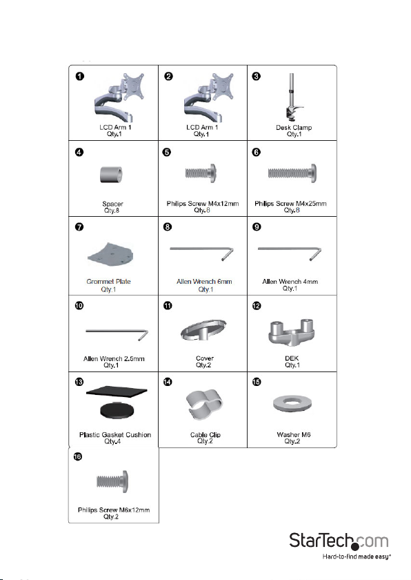
Introduction
Packaging Contents
Instruction Manual
1
Page 5
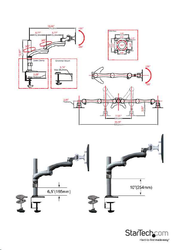
Product Diagram
Instruction Manual
2
Page 6
Installation
WARNING! It is the installer’s responsibility to ensure that the combined weight of all
components does not exceed the maximum weight capacity 13.6 kg (30 lbs) of the
mounting arm.
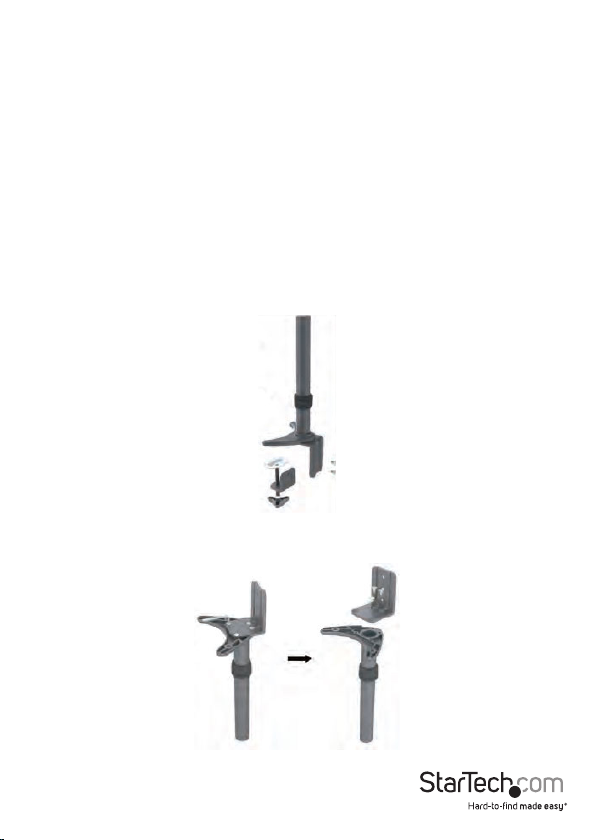
Converting the Desk Clamp to a Grommet Clamp
The Dual Monitor Arm can be clamped to a desk / table, or mounted through a
grommet hole. The following instructions outline how to convert the default Desk
Clamp setup to a Grommet Clamp.
Skip to the next section (Desk / Grommet Mounting) if you are not using the Grommet
Clamp method.
1. Remove the 2 hex screws from the back of the desk clamp using the 4mm Allen
Wrench (9) to disconnect the bottom half of the clamp.
2. Remove the 4 hex screws from the base of the pole using the 4mm Allen Wrench (9)
to disconnect the top half of the clamp.
Instruction Manual
3
Page 7

3. Using the 4 hex screws removed in Step 2, install the Grommet Plate (7) to the
base of the pole.
7
4. Remove the screw and 2 washers shown using a Phillips screwdriver to disconnect
the threaded shaft from the base of the clamp, then slide the plate back onto the
shaft.
Instruction Manual
4
Page 8

Desk / Grommet Mounting
1. Adjust the height of the Desk Clamp (3) to t your desk surface (if applicable).
2. Place the 4 Plastic Gasket Cushions (13) as shown.
Instruction Manual
5
Page 9

3. Desk Clamp: Place the Desk Clamp (3) opening around the edge of your desktop in
your desired location and tighten by hand to secure. Ensure that the Desk Clamp is
making full contact with the desk surface.
Grommet Clamp: Place the base of the unit over the grommet hole and thread the
clamp into the Grommet Plate until the clamp holds rmly against the bottom of
the desk.
4. Loosen the collar on the support post and adjust to the desired height.
Instruction Manual
6
Page 10

5. Slide the DEK (12) onto the support post so that it rests on the collar. Once
adjusted to the desired height, tighten into place using the 2.5mm Allen
Wrench (10).
Attaching the Displays
1. Carefully place your display face down on a protective surface to access the
mounting points.
2. Depending on the depth of the mounting holes on your display, attach the display
using either the M4x12mm (5), or the M4x25mm (6) with the provided spacers (4).
Instruction Manual
7
Page 11

3. Using a Phillips screwdriver, tighten the screws until the bracket is rmly attached to
the back of the display.
WARNING! Do not over-tighten the screws and stop immediately if you encounter
resistance to avoid damage to your display. Ensure that all spacers and screws being
used are the same length and thread type.
4. Repeat for the second LCD display.
Instruction Manual
8
Page 12

Attaching the LCD Arm Assembly
1. Slide the LCD Arm Assembly (1 or 2) down onto the DEK (12).
2. Tighten the set screw using the 2.5mm Allen Wrench (10).
Instruction Manual
9
Page 13

3. Place the Cover (11) over the mounting post and insert 1 x M6x12mm Phillips Screw
(16) with 1 x Plastic Washer (15). Tighten using a Phillips screwdriver.
4. Repeat for the other side.
Instruction Manual
10
Page 14

Cable Management
Note: When attaching cables and routing through the cable management channels,
ensure that you leave enough slack to avoid stretching / pulling out the cables when
moving the arm.
1. Connect your cables to your displays and position the mounting arm in its fully
extended position to ensure that the cables you are using are long enough to allow
for proper movement.
2. Feed the cables into the cable management channels on the underside of the arms
as shown.
3. Use the Cable Clip (14) to secure the display cables to the pole.
Instruction Manual
11
Page 15

Adjusting LCD Arm Resistance
WARNING! Forced movement of the LCD Arms or Mount Brackets without loosening
the screws may damage the product or the mounted displays.
Always support your display from underneath when making any adjustments to the
LCD Arms or Mount Brackets to avoid damage to the display.
Note: For all adjustments outlined below, turning the screw clockwise will increase the
resistance, while turning the screw counter-clockwise will decrease resistance.
To increase / decrease the tilt resistance, adjust the set screw located on the side of the
Mount Bracket joint, using the 6mm Allen Wrench (8).
Instruction Manual
12
Page 16

To increase / decrease the pan / swing resistance, adjust the set screw located on the
top of the Mount Bracket joint, using the 4mm Allen Wrench (9).
To increase / decrease the swivel resistance on either of the elbow joints of the
articulating LCD Arms, adjust the set screws indicated below, using the 2.5mm Allen
Wrench (10)
Instruction Manual
13
Page 17

Specications
Weight Capacity 30 lbs (13.6 kg)
Max Display Size 24”
VESA Compatibility 75x75 mm and 100x100 mm
Maximum Extension 18.66 in (474 mm)
Maximum Mounting Surface
Thickness
3 in (75 mm)
Instruction Manual
14
Page 18

Technical Support
StarTech.com’s lifetime technical support is an integral part of our commitment to
provide industry-leading solutions. If you ever need help with your product, visit
www.startech.com/support and access our comprehensive selection of online tools,
documentation, and downloads.
For the latest drivers/software, please visit www.startech.com/downloads
Warranty Information
This product is backed by a two year warranty.
In addition, StarTech.com warrants its products against defects in materials
and workmanship for the periods noted, following the initial date of purchase.
During this period, the products may be returned for repair, or replacement with
equivalent products at our discretion. The warranty covers parts and labor costs only.
StarTech.com does not warrant its products from defects or damages arising from
misuse, abuse, alteration, or normal wear and tear.
Limitation of Liability
In no event shall the liability of StarTech.com Ltd. and StarTech.com USA LLP (or their
ocers, directors, employees or agents) for any damages (whether direct or indirect,
special, punitive, incidental, consequential, or otherwise), loss of prots, loss of business,
or any pecuniary loss, arising out of or related to the use of the product exceed the
actual price paid for the product. Some states do not allow the exclusion or limitation
of incidental or consequential damages. If such laws apply, the limitations or exclusions
contained in this statement may not apply to you.
Instruction Manual
15
Page 19

Hard-to-nd made easy. At StarTech.com, that isn’t a slogan. It’s a promise.
StarTech.com is your one-stop source for every connectivity part you need. From
the latest technology to legacy products — and all the parts that bridge the old and
new — we can help you nd the parts that connect your solutions.
We make it easy to locate the parts, and we quickly deliver them wherever they need
to go. Just talk to one of our tech advisors or visit our website. You’ll be connected to
the products you need in no time.
Visit www.startech.com for complete information on all StarTech.com products and
to access exclusive resources and time-saving tools.
StarTech.com is an ISO 9001 Registered manufacturer of connectivity and technology
parts. StarTech.com was founded in 1985 and has operations in the United States,
Canada, the United Kingdom and Taiwan servicing a worldwide market.
 Loading...