

Page 1
Manual Revision: 11/06/2018
User Manual
For the latest information and specications visit
www.startech.com/ARMBARDUOG
Dual-Monitor Desk Mount - with
Grommet/Desk-Clamp Mount
SKU#: ARMBARDUOG
*actual product may vary from photos
Page 2

User Manual
i
Compliance Statements
Use of Trademarks, Registered Trademarks, and other
Protected Names and Symbols
This manual may make reference to trademarks, registered trademarks, and
other protected names and/or symbols of third-party companies not related in
any way to StarTech.com. Where they occur these references are for illustrative
purposes only and do not represent an endorsement of a product or service
by StarTech.com, or an endorsement of the product(s) to which this manual
applies by the third-party company in question. Regardless of any direct
acknowledgement elsewhere in the body of this document, StarTech.com
hereby acknowledges that all trademarks, registered trademarks, service marks,
and other protected names and/or symbols contained in this manual and
related documents are the property of their respective holders.
PHILLIPS® is a registered trademark of Phillips Screw Company in the United
States or other countries.
Page 3

ii
Safety Statements
Safety Measures
• Product installation and/or mounting should be completed by a certied
professional as per the local safety and building code guidelines.
Mesures de sécurité
• L’installation et/ou le montage du produit doit être réalisé par un
professionnel certié et dans le respect des normes locales et du code de
construction local.
安全対策
• 製品の設置やマウントは、使用地域の安全ガイドラインおよび建築基準に
従い、有資格の専門業者が行うようにしてください。
Misure di sicurezza
• L’installazione e/o il montaggio dei prodotti devono essere eseguiti da un
tecnico professionale certicato che conosca le linee guida locali sulle norme
edilizie e sulla sicurezza.
Säkerhetsåtgärder
• Installation och/eller montering får endast göras av behöriga yrkespersoner
och enligt gällande lokala förordningar för säkerhet och byggnormer.
Warning Statements
• Make sure to assemble this product according to the instructions. Failure to
do so might result in personal injury or property damage.
• Never use this product if parts are missing or damaged.
User Manual
Page 4

User Manual
Table of Contents
Compliance Statements ........................................................................i
Safety Statements ..................................................................................ii
Warning Statements ..............................................................................iii
Product Information ..............................................................................1
Package Contents .....................................................................................................................................1
Product Dimensions ..............................................................................2
Front View .................................................................................................................................................... 2
Side View ..................................................................................................................................................... 2
Top View ....................................................................................................................................................... 3
Angled View (Includes Tilt Angles) ......................................................................................................3
Grommet Mount ....................................................................................................................................... 4
VESA Mount ............................................................................................................................................... 4
Technical Specications ........................................................................5
Requirements .........................................................................................6
Installation ..............................................................................................7
Attach the ARMBARDUOG to Your Mounting Surface ................................................................. 7
Attach Monitor Arms to the Column .................................................................................................12
Attach Monitors ......................................................................................................................................... 14
Attach the Cable-Management Clips ................................................................................................ 17
Operation ................................................................................................18
Adjust the Position of the Monitors ...................................................................................................18
Warranty information ............................................................................ 21
Page 5
User Manual
1
Product Information
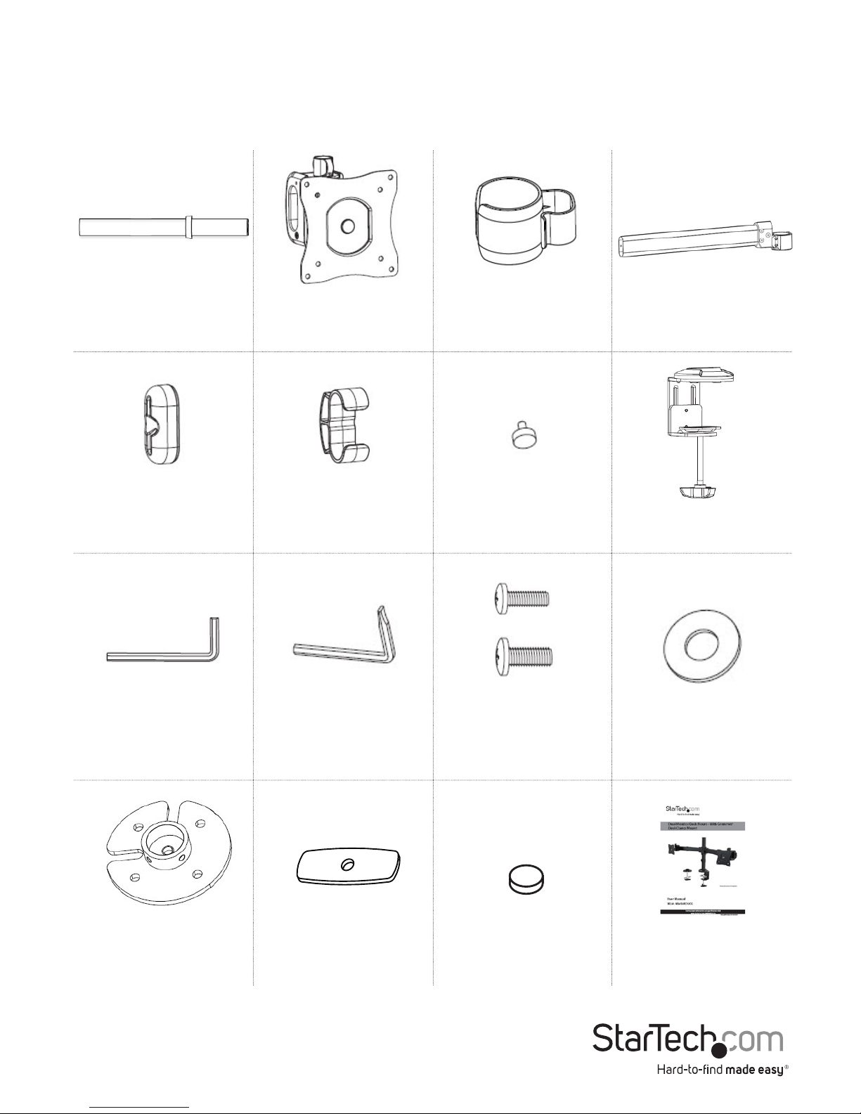
Package Contents
Column x 1 VESA Adapter x 2
Cable-
Management Clips
(Column) x 2
Monitor Arms x 2
End Caps x 2
Cable-
Management Clips
(Monitor Arm) x 2
End-Cap Screws
x 2
Desk-Mount
Clamp x 1
Hex Key x 1
Hex Key
Screwdriver x 1
M4x14 mm Screws
x 8 (narrow)
M5x14 mm Screws
x 8 (wide)
Flat Washers x 8
Grommet-
Mounting Adapter
x 1
Grommet-
Mounting Plate x 1
Rubber Pads x 5 Instruction Manual
x 1
Page 6
1 1
2
3
4
User Manual
2
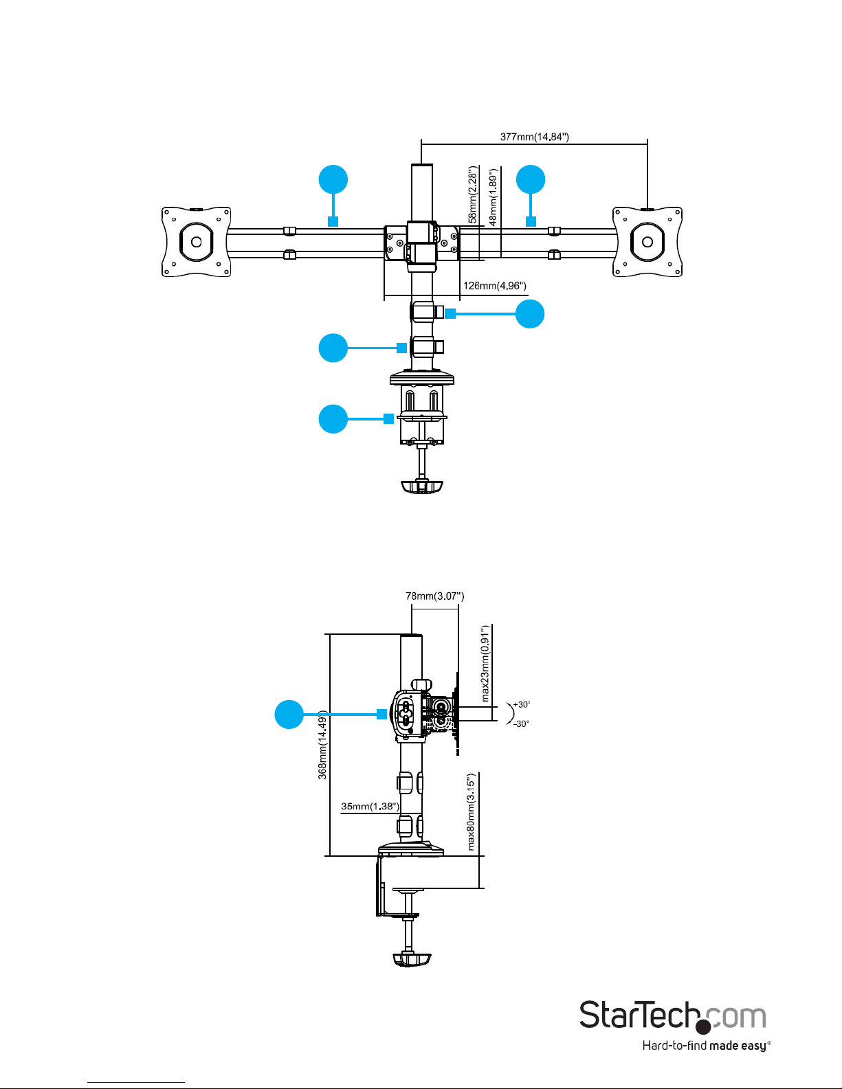
Product Dimensions
Front View
1. Monitor Arms
2. Cable-Management Clips (Column)
3. Column
4. Desk-Mount Clamp
Side View
1. End Caps
1
Page 7
User Manual
3
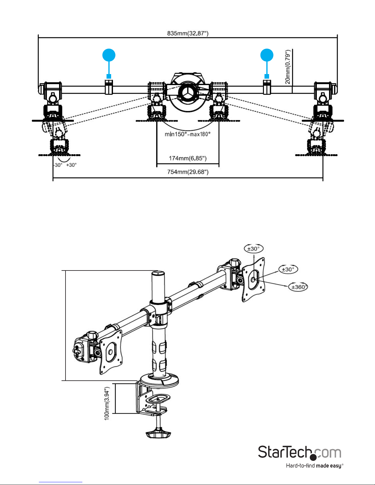
Top View
1. Cable-Management Clips (Monitor Arm)
Angled View (Includes Tilt Angles)
11
368mm (14.49’’)
Page 8
User Manual
4
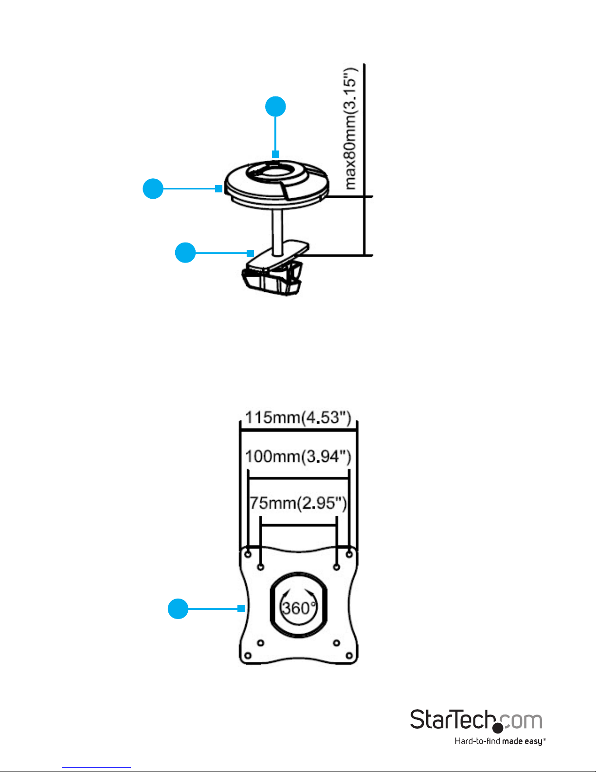
Grommet Mount
1. Mounting Cover
2. Grommet-Mounting Adapter
3. Grommet-Mounting Plate
VESA Mount
1. VESA Adapter
1
2
3
1
Page 9

User Manual
5
Technical Specications
Type of Measurement Measurement
VESA mounting hole pattern
75x75
100x100
Weight capacity
Up to 17.6 lb. (8 kg)
per monitor mount
Tilt
+30 to -30
Screen size
330 to 686 mm
(13 to 27 in.)
Rotate
360
Swivel
+30 to -30
kg
Page 10

User Manual
6
Requirements
• Two People for Installation
• Mounting Surface
• Desk-Mount Clamp (on Desk Edge) or Grommet Mount (in Desktop Grommet)
• Two Monitors
Note: Both Monitors must conform to the size, weight and VESA pattern requirements (see Technical Specications).
• Phillips Head Screwdriver
Page 11

User Manual
7
Installation
Attach the ARMBARDUOG to Your Mounting Surface
There are two ways that you can attach the ARMBARDUOG to a mounting surface:
a Desk-Mount Clamp or a Grommet Mount. The Desk-Mount Clamp ships
preassembled.
Use the Desk Clamp to Attach the ARMBARDUOG
Warning! Ensure that the weight of the Monitors does not exceed the weight capacity
of this product. If you exceed the weight capacity, you may experience personal
injury or damage to your Monitors and ARMBARDUOG. This product can support the
following weight capacities: Up to 8 kg (17.6 lb.) per monitor mount, for a total of 16 kg
(35.2 lb.).
1. Remove the Mounting Cover from the top of the Desk-Mount Clamp. (Figure 1)
Mounting
Cover
Desk-Mount
Clamp
Figure 1
2. Thread the Column through the Mounting Cover that you removed from the DeskMount Clamp.
(Figure 2)
Figure 2
Column
Mounting Cover
Page 12

User Manual
8
3. Screw the Column into the top of the Desk-Mount Clamp. (Figure 3)
4. Use the Hex Key Screwdriver to tighten the screws in the Desk-Mount Clamp.
(Figure 4)
Column
Desk Clamp
Hex Key
Screwdriver
Figure 3 Figure 4
5. Seat the Mounting Cover so that it is ush with the top of the Desk-Mount Clamp.
(Figure 5)
Figure 5
Mounting Cover
Desk-Mount Clamp
Column
Page 13

User Manual
9
6. Remove the backing from the ve Rubber Pads and attach them underneath the
top of the Desk-Mount Clamp, on the surface touching the table. (Figure 6)
7. Turn the knob on the Desk-Mount Clamp counterclockwise until it reaches the
thickness of the Desk.
Note: The Desk-Mount Clamp can accommodate a Mounting Surface that is
between 10 and 80 millimeters (0.4 and 3.1 inches) thick.
8. Slide the Desk-Mount Clamp over the edge of the Mounting Surface (Figure 7).
9. Turn the Knob clockwise to tighten the Desk-Mount Clamp.
Figure 7
Desk-Mount
Clamp
Knob
Figure 6
Page 14

User Manual
10
2. Insert a Phillips Head Screwdriver through the top of the Desk-Mount Clamp and
unscrew the Screw. Remove the Washer, Screw, Plate, and Rod. (Figure 9)
Tip! Keep the Washer, Screw and Plate in a safe place so that you can use them again
if you want to switch back to the Desk-Mount Clamp.
Figure 9
Desk-Mount
Clamp
Plate
Screw
Rod
Screwdriver
Mounting
Cover
Desk-Mount
Clamp
Figure 8
Use the Grommet Mount to Attach the ARMBARDUOG
Warning! Ensure that the weight of the Monitors does not exceed the weight capacity
of this product. If you exceed the weight capacity, you may experience personal
injury or damage to your Monitors and ARMBARDUOG. This product can support the
following weight capacities: Up to 8 kg (17.6 lb.) per monitor mount, for a total of 16 kg
(35.2 lb.).
1. Remove the Mounting Cover from the top of the Desk-Mount Clamp. (Figure 8)
Page 15

User Manual
11
3. Ax the Rubber Pads to the bottom of the Grommet-Mounting Adapter.
(Figure 10)
Figure 10
Grommet-
Mounting
Adapter
Rubber Pads
4. Slide the Mounting Cover over the Column and screw the Column into the top of
the Grommet-Mounting Adapter. (Figure 11)
Figure 11
Grommet-Mounting
Adapter
Mounting
Cover
Column
5. Use the hex side of the Hex Key Screwdriver to tighten the two Hex Screws in the
Grommet-Mounting Adapter, and push down the Mounting Cover so that it sits
ush with the Grommet-Mounting Adapter. (Figure 12)
Figure 12
Grommet-Mounting
Adapter
Mounting
Cover
Column
Hex Key Screwdriver
Page 16

User Manual
12
Attach Monitor Arms to the Column
1. Use the Hex Key Screwdriver to loosen the two screws in the Collar.
2. Slide the Collar to the height that you want the two Monitors to sit at, and use the
Hex Key Screwdriver to tighten the two Screws in the Collar. (Figure 14)
Figure 14
Column
Collar
3 mm hex key
6. Thread the Grommet-Mounting Plate onto the Rod.
7. Place the assembled Column and Grommet-Mounting Adapter over the
grommet hole in the Mounting Surface. On the underside of the Mounting
Surface, insert the Rod up through the grommet hole and into the Column.
Note: The Grommet-Mounting Adapter can accommodate a grommet hole that is
between 10.5 and 50 millimeters (0.41 and 1.96 inches) in diameter.
Note: The Grommet-Mounting Adapter can accommodate a Mounting Surface that
is between 10 and 80 millimeters (0.4 and 3.1 inches) thick.
8. Turn the Knob clockwise to tighten. (Figure 13)
Figure 13
Grommet-
Mounting Plate
Rod
Column
Knob
Page 17

User Manual
13
3. Slide one of the Monitor Arms down the Column so that it sits against the Collar.
4. Slide a second Monitor Arm down the Column so that it sits against the rst
Monitor Arm. (Figure 15)
Note: When you assemble the ARMBARDUOG for the rst time, you need to use the
Hex Key to tighten the Screws in each of the Monitor Arm joints. (Figure 16)
Figure 15
Monitor Arm
Monitor Arm
Column
Hex Key
Figure 16
Collar
Page 18

14
Attach Monitors
Warning! Attaching the Monitors is a two-person job. Do not attempt to complete
this task by yourself.
To accommodate dierent Monitor designs, the ARMBARDUOG comes with two sets
of Screws that are dierent lengths and diameters.
To select the appropriate Screws for the type of Monitors that you’re using, complete
the following:
• Determine whether the back of the Monitors are ush or inset.
• Determine the depth of the mounting holes on the Monitors.
• Determine the diameter of the mounting holes on the Monitors.
1. Position one of the VESA Adapters over the mounting holes on the back of one of
the Monitors.
Note: Make sure that you position the VESA Adapter so that the adjustment
thumbscrew on the VESA Adapter is facing towards the top of the Monitor.
2. Position four of the Flat Washers over the holes on the VESA Adapter.
3. Insert four of the M4x14 mm Screws or the M5x14 mm Screws through the
Washers, the VESA Adapter, and into the Monitor. (Figure 17)
4. Use a Phillips Screwdriver to tighten the Screws.
Warning! Do not over-tighten the Screws. If you encounter resistance while you’re
tightening the Screws, stop tightening. Failure to do so could result in damage to the
Monitor.
Top of monitor
M4x14 mm Screw
OR
M5x14 mm Screw
Flat Washer
Figure 17
VESA Adapter
User Manual
Page 19

15
5. Complete steps 1 to 4 to add a VESA Adapter to a second monitor.
6. Slide one of the VESA Adapters with the Monitor attached over the end of one of
the Monitor Arms attached to the Column.
7. Slide the second VESA Adapter and Monitor onto the other Monitor Arm. (Figure
18)
8. Place an End Cap over the end of each of the Monitor Arms attached to the
Column. (Figure 19)
Note: Ensure that the hole on each of the End Caps with is lined up with the
corresponding hole on the end of each of the Monitor Arms.
Figure 19
Monitor Arm
End Cap
Figure 18
Monitor
Monitor Arm
Monitor Arm
Column
VESA Adapter
VESA Adapter
Monitor
User Manual
Page 20

16
Figure 20
End Cap
Thumbscrew
User Manual
9. Insert an End-Cap Screw through the hole in each of the End Caps and into the
Monitor Arms, and tighten the End-Cap Screws in place. (Figure 20)
Page 21

User Manual
17
Figure 21
Cable-Management
Clip (Monitor Arm)
Cable-Management
Clip (Column)
Attach the Cable-Management Clips
1. Snap one of the Cable-Management Clips (Monitor Arm) over each of the two
Monitor Arms. (Figure 21)
2. Snap the two Cable-Management Clips (Column) over the Column. (Figure 22)
3. Route the Monitor Cables through the Cable-Management Clips on the Monitor
Arms and through the Cable-Management Clips on the Column.
Cable-Management
Clips (Column)
Column
Figure 22
Page 22

18
Operation
Adjust the Position of the Monitors
You can congure the Monitors in many ways: (Figure 23 & 24):
-30
+30
-30
+30
+30 to -30
+30 to -30
360
360
-30
+30
-30
+30
+30 to -30
360
360
Figure 24
User Manual
0 to 30
0 to 30
Figure 23
+30 to -30
Page 23

19
1. To position the Monitors:
• To adjust the angle of the Monitor Arms, use the Hex Key to loosen the two
Screws at each of the Monitor Arm joints. Position the Monitors as desired,
and use the Hex Key to tighten the Screws and lock the Monitors into
position. (Figure 25)
Figure 25
Hex Key
• To tilt the Monitors, use the Hex Key to loosen the Screw in the sides of the
VESA Adapters. Position the Monitors as desired, and use the Hex Key to
tighten the Screws and lock the Monitors into position. (Figure 26)
Figure 26
Hex Key
User Manual
Page 24

Figure 27
Adjustment
Screw
20
• To raise or lower the Monitors minutely, use the Adjustment Screws located
on the top of the VESA Adapters. (Figure 27)
• To move the Monitors along the Monitor Arms, use a Phillips Head
Screwdriver to loosen the Screw located on the underside of each of the
VESA Adapters. Move the Monitors left or right on the Monitor Arms, and
tighten each of the Screws when the Monitors are in the desired locations.
(Figure 28)
Warning! Make sure that you loosen the Screw on the underside of the VESA
Adapters before you move them along the Monitor Arms. If you move the VESA
Adapters without loosening the Screws, you might damage the surface of the
Monitor Arms.
Figure 28
User Manual
Page 25

User Manual
21
Warranty Information
This product is backed by a three-year warranty.
StarTech.com warrants its products against defects in materials and
workmanship for the periods noted, following the initial date of purchase.
During this period, the products may be returned for repair, or replacement with
equivalent products at our discretion. The warranty covers parts and labor costs
only.
StarTech.com does not warrant its products from defects or damages arising
from misuse, abuse, alteration, or normal wear and tear.
Limitation of Liability
In no event shall the liability of StarTech.com Ltd. and StarTech.com USA LLP (or
their ocers, directors, employees or agents) for any damages (whether direct
or indirect, special, punitive, incidental, consequential, or otherwise), loss of
prots, loss of business, or any pecuniary loss, arising out of or related to the use
of the product exceed the actual price paid for the product.
Some states do not allow the exclusion or limitation of incidental or
consequential damages. If such laws apply, the limitations or exclusions
contained in this statement may not apply to you.
Page 26

Hard-to-nd made easy. At StarTech.com, that isn’t a
slogan. It’s a promise.
StarTech.com is your one-stop source for every connectivity part you need.
From the latest technology to legacy products — and all the parts that
bridge the old and new — we can help you nd the parts that connect your
solutions.
We make it easy to locate the parts, and we quickly deliver them wherever
they need to go. Just talk to one of our tech advisors or visit our website.
You’ll be connected to the products you need in no time.
Visit www.startech.com for complete information on all StarTech.com
products and to access exclusive resources and time-saving tools.
StarTech.com is an ISO 9001 Registered manufacturer of connectivity and
technology parts. StarTech.com was founded in 1985 and has operations
in the United States, Canada, the United Kingdom and Taiwan servicing a
worldwide market.
Reviews
Share your experiences using StarTech.com products, including product
applications and setup, what you love about the products, and areas for
improvement.
StarTech.com Ltd.
45 Artisans Cres.
London, Ontario
N5V 5E9
Canada
StarTech.com LLP
2500 Creekside Pkwy.
Lockbourne, Ohio
43137
U.S.A.
StarTech.com Ltd.
Unit B, Pinnacle
15 Gowerton Rd.,
Brackmills
Northampton
NN4 7BW
United Kingdom
FR: fr.startech.com
DE: de.startech.com
ES: es.startech.com
NL: nl.startech.com
IT: it.startech.com
JP: jp.startech.com
 Loading...