

Page 1
10/100Mbps VDSL2 Ethernet Extender Kit over
Single Pair Wire - 1.5km
110VDSLEXT2 / 110VDSLEX2GB / 110VDSLEX2EU
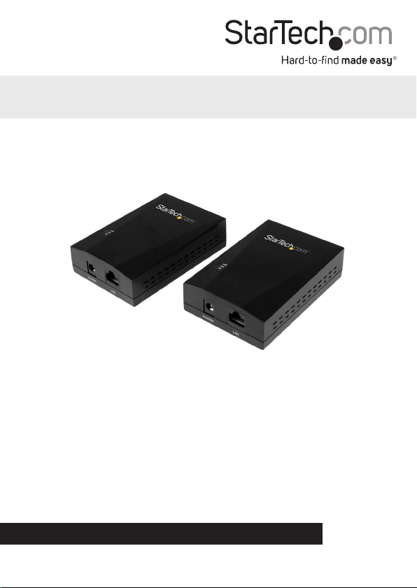
*actual product may vary from photos
DE: Bedienungsanleitung - de.startech.com
FR: Guide de l'utilisateur - fr.startech.com
ES: Guía del usuario - es.startech.com
IT: Guida per l'uso - it.startech.com
NL: Gebruiksaanwijzing - nl.startech.com
PT: Guia do usuário - pt.startech.com
For the most up-to-date information, please visit: www.startech.com
Manual Revision: 01/07/2015
Page 2

FCC Compliance Statement
This equipment has been tested and found to comply with the limits for a Class B digital
device, pursuant to part 15 of the FCC Rules. These limits are designed to provide reasonable
protection against harmful interference in a residential installation. This equipment
generates, uses and can radiate radio frequency energy and, if not installed and used in
accordance with the instructions, may cause harmful interference to radio communications.
However, there is no guarantee that interference will not occur in a particular installation. If
this equipment does cause harmful interference to radio or television reception, which can
be determined by turning the equipment o and on, the user is encouraged to try to correct
the interference by one or more of the following measures:
• Reorient or relocate the receiving antenna.
• Increase the separation between the equipment and receiver.
• Connect the equipment into an outlet on a circuit dierent from that to which the
receiver is connected.
• Consult the dealer or an experienced radio/TV technician for help
This device complies with part 15 of the FCC Rules. Operation is subject to the following
two conditions: (1) This device may not cause harmful interference, and (2) this device must
accept any interference received, including interference that may cause undesired operation.
Changes or modications not expressly approved by StarTech.com could void the user’s
authority to operate the equipment.
Industry Canada Statement
This Class B digital apparatus complies with Canadian ICES-003.
Cet appareil numérique de la classe [B] est conforme à la norme NMB-003 du Canada.
CAN ICES-3 (B)/NMB-3(B)
Use of Trademarks, Registered Trademarks, and other Protected Names and Symbols
This manual may make reference to trademarks, registered trademarks, and other
protected names and/or symbols of third-party companies not related in any way to
StarTech.com. Where they occur these references are for illustrative purposes only and do not
represent an endorsement of a product or service by StarTech.com, or an endorsement of the
product(s) to which this manual applies by the third-party company in question. Regardless
of any direct acknowledgement elsewhere in the body of this document, StarTech.com hereby
acknowledges that all trademarks, registered trademarks, service marks, and other protected
names and/or symbols contained in this manual and related documents are the property of
their respective holders.
Instruction Manual
Page 3

Table of Contents
Introduction ............................................................................................1
Packaging Contents ................................................................................................................................. 1
System Requirements .............................................................................................................................. 1
Product Overview ..................................................................................2
Front View ....................................................................................................................................................2
Rear View ...................................................................................................................................................... 2
Side View ...................................................................................................................................................... 2
LED Indicators .........................................................................................3
Installation .............................................................................................4
Hardware Installation ............................................................................................................................. 4
DIP Switch and Mode Settings .............................................................5
Technical Support ..................................................................................6
Warranty Information ............................................................................6
Instruction Manual
i
Page 4

Introduction
Packaging Contents
• 1x Ethernet VDSL2 - Transmitter
• 1x Ethernet VDSL2 - Receiver
• 2x RJ45 Cables
• 8x Rubber Feet
• 2x Power Adapters
• 1x Instruction Manual
• 2x Wall mount screws and anchors
System Requirements
• 10/100 Mbps Ethernet Network
• Available AC electrical outlets
• RJ11 cable or RJ11 lines in building infrastructure
Instruction Manual
1
Page 5

Product Overview
The Ethernet Extender Kit consists of x2 Ethernet VDSL2 Transmitter/Receiver units.
Either unit can be used at either end of your conguration (transmitting end or
receiving end), however the DIP switch settings should be modied according to your
specic needs based on direction of trac.
By default, all DIP Switch settings on each of the two units are set to the
downward (OFF) position.
See the DIP Switch and Mode Settings section for more information.
Front View
Rear View
Side View
Instruction Manual
DC Power Input
RJ45 Port RJ45 Port
RJ11 VDSL Port RJ11 VDSL Port
LED Indicators
DIP Switch
DIP Switch
DC Power Input
2
Unit 1
Unit 2
Page 6

LED Indicators
LED
(Green)
PWR
(Power)
ETH
(Ethernet)
DSL (VDSL) No VDSL Link/Connection Connected
No RJ45 Link/Connection Connected Activity
OFF ON (Solid) FLASHING
Power O Power On NA
Slow - Establishing
Connection
Fast – Sync / Activity
Instruction Manual
3
Page 7

Installation
Hardware Installation
One of the Ethernet Extender Kits units should be considered a “Transmitting Unit”,
while the other should be considered a “Receiver Unit.”
Transmitter Unit
1. Place one of the units at the local location, this unit will act as the Transmitter Unit.
2. Connect the provided power adapter from an AC electrical outlet to the DC Power
Input on the Transmitter Unit. The “PWR” LED should light up solid.
3. Set all four of the DIP switches to the downward (OFF) position. This places the
Transmitter Unit in CO mode (Central Oce Mode).
4. Connect an RJ45 Ethernet cable to the RJ45 Port on the Transmitter Unit.
5. Connect the other end of the Ethernet cable into your Ethernet network device (eg:
Ethernet switch, modem, etc). The “ETH” LED should light up solid.
6. Connect an RJ11 phone cable into the RJ11 VDSL Port on the Transmitter Unit.
7. Connect the opposite end of the RJ11 cable to the RJ11 VDSL Port on the Receiver
Unit (or to your buildings RJ11 phone line infrastructure, depending on your setup).
Optional: Congure DIP switches 2 through 4 as necessary (see the “DIP Switch and
Mode Settings” section).
Receiver Unit
1. Place the second unit at the remote location, this unit will act as the Receiver Unit.
2. Connect the provided power adapter from an AC electrical outlet to the DC Power
Input on the Receiver Unit. The “PWR” LED should light up solid.
3. Set the DIP switch setting #1 to the upward (ON) position, with the remaining 3
DIP switches set to the downward (OFF) position. This places the Receiver Unit in
CPE mode (Customer Premises Equipment Mode).
4. If previously not completed, connect the RJ11 cable that was inserted into the RJ11
VDSL Port on the Transmitter Unit directly to the RJ11 VDSL Port on the Receiver
Unit (or from your buildings existing RJ11 analog telephone wiring, depending on
the setup from step 7 above.)
5. If the Transmitter and Receiver Units are able to successfully communicate with
each other, the “DSL” LED should ash slow, then fast while establishing a
connection, and eventually light up solid. The “DSL” LED will continue to ash when
there is activity between the Transmitter and Receiver Unit.
6. Connect your Ethernet network device (eg: Ethernet switch, modem, etc) to the
RJ45 Port on the Receiver Unit. The “ETH” LED should light up solid.
Optional: Congure DIP switches 2 through 4 as necessary (see the “DIP Switch and
Mode Settings” section).
Instruction Manual
4
Page 8

DIP Switch and Mode Settings
The Ethernet Extender Kit units have a 4-position DIP switch for conguration of CO/
CPE, Prole, Band, and SNR.
By default, all DIP switch settings for both units are set to the downward “OFF”
position.
DIP1 DIP2 DIP3 DIP4
Function CO/CPE Mode Prole Mode Band Mode SNR Target
ON CPE 17a Symmetric 6dB
OFF CO 30a Asymmetric 9dB
For initial setup, DIP switch 1 is usually set to the downward (OFF) position, ensuring
the unit is set to CO mode, set the 2nd unit to CPE mode by setting DIP switch 1 to the
upward (ON) position.
When using the Ethernet Extender Kit, one end (Transmitter or Receiver) must always
be set to “CO” (Central Oce), mode, while the opposite end must always be set to
“CPE” (Customer Premises Equipment) mode.
To ensure the Ethernet Extender Kit operates as intended with no problems,
errors, or disruptions, DIP switch settings 2 through 4 should be set to the same
position on both your Transmitter and Receiver Units.
CO or CPE Mode
Setting each unit to CO or CPE mode is usually based on which direction you want
the most bandwidth delivered. “Download” bandwidth, data sent from CO to CPE, is
generally higher than “Upload” bandwidth from CPE to CO.
If you need higher bandwidth from the Transmitter Unit to the Receiver Unit, set DIP
switch 1 to the downward (OFF) position at the transmitting end and the upward (ON)
position at the receiving end.
If you need higher bandwidth from the Receiver Unit to the Transmitter Unit, set DIP
switch 1 to the upward (ON) position at the receiving end, and the downward (OFF)
Instruction Manual
5
Page 9

position at the transmitting end.
Prole Mode
Prole Mode is the VDSL2 prole, 17a or 30a, with 30a allowing higher bandwidth
at longer distances. Set this DIP switch to the upward (ON) position for 17a, or the
downward (OFF) position for 30a, depending on your network requirements and
preferences.
Band Mode
Band Mode places the unit in either Symmetric or Asymmetric mode. Set this DIP
switch to the upward (ON) position for Symmetric mode, with both downstream and
upstream transmissions operating on the G.997 band plan, or set to the downward
(OFF) position for or Asymmetric mode, with asymmetric short range transmissions
operating at the highest available line rate.
SNR Target
SNR Target can be set for the unit to operate with ratios up to 6 or 9 dB. Set this DIP
switch to the upward (ON) position for a SNR ratio up to 6dB, or to the downward (OFF)
position for a SNR ratio up to 9dB.
Instruction Manual
6
Page 10

Technical Support
StarTech.com’s lifetime technical support is an integral part of our commitment to
provide industry-leading solutions. If you ever need help with your product, visit
www.startech.com/support and access our comprehensive selection of online tools,
documentation, and downloads.
For the latest drivers/software, please visit www.startech.com/downloads
Warranty Information
This product is backed by a two year warranty.
In addition, StarTech.com warrants its products against defects in materials
and workmanship for the periods noted, following the initial date of purchase.
During this period, the products may be returned for repair, or replacement with
equivalent products at our discretion. The warranty covers parts and labor costs only.
StarTech.com does not warrant its products from defects or damages arising from
misuse, abuse, alteration, or normal wear and tear.
Limitation of Liability
In no event shall the liability of StarTech.com Ltd. and StarTech.com USA LLP (or their
ocers, directors, employees or agents) for any damages (whether direct or indirect,
special, punitive, incidental, consequential, or otherwise), loss of prots, loss of business,
or any pecuniary loss, arising out of or related to the use of the product exceed the
actual price paid for the product. Some states do not allow the exclusion or limitation
of incidental or consequential damages. If such laws apply, the limitations or exclusions
contained in this statement may not apply to you.
Instruction Manual
7
Page 11

Hard-to-nd made easy. At StarTech.com, that isn’t a slogan. It’s a promise.
StarTech.com is your one-stop source for every connectivity part you need. From
the latest technology to legacy products — and all the parts that bridge the old and
new — we can help you nd the parts that connect your solutions.
We make it easy to locate the parts, and we quickly deliver them wherever they need
to go. Just talk to one of our tech advisors or visit our website. You’ll be connected to
the products you need in no time.
Visit www.startech.com for complete information on all StarTech.com products and
to access exclusive resources and time-saving tools.
StarTech.com is an ISO 9001 Registered manufacturer of connectivity and technology
parts. StarTech.com was founded in 1985 and has operations in the United States,
Canada, the United Kingdom and Taiwan servicing a worldwide market.
 Loading...