

Page 1
60W Ultra PoE Injector (Midspan) and Splitter Bundle
Actual product may vary from photos
User Manual
SKU#: UPOESPLT1G
For the latest information and specications visit
www.startech.com/UPOESPLT1G
Manual Revision: 10/02/2018
Page 2

Compliance Statements
FCC Compliance Statement
This equipment has been tested and found to comply
with the limits for a Class A digital device, pursuant to Part
15 of the FCC rules. These limits are designed to provide
reasonable protection against harmful interference when the
equipment is operated in a commercial environment. This
equipment generates, uses and can radiate radio frequency
energy and, if not installed and used in accordance with the
instruction manual, may cause harmful interference to radio
communications. Operation of this equipment in a residential
area is likely to cause harmful interference, in which case the
user will be required to correct the interference at their own
expense.
This device complies with part 15 of the FCC Rules. Operation is
subject to the following two conditions: (1) This device may not
cause harmful interference, and (2) this device must accept any
interference received, including interference that may cause
undesired operation.
For the State of California
WARNING: Cancer and Reproductive Harm
www.P65Warnings.ca.gov
To view manuals, videos, drivers, downloads, technical drawings, and more visit www.startech.com/support
i
Page 3

Use of Trademarks, Registered Trademarks, and other
Protected Names and Symbols
This manual may make reference to trademarks, registered
trademarks, and other protected names and/or symbols of
third-party companies not related in any way to StarTech.com.
Where they occur these references are for illustrative purposes
only and do not represent an endorsement of a product or
service by StarTech.com, or an endorsement of the product(s)
to which this manual applies by the third-party company
in question. Regardless of any direct acknowledgement
elsewhere in the body of this document, StarTech.com hereby
acknowledges that all trademarks, registered trademarks,
service marks, and other protected names and/or symbols
contained in this manual and related documents are the
property of their respective holders.
Warning Statements
Never use this product if parts are missing or damaged.
To view manuals, videos, drivers, downloads, technical drawings, and more visit www.startech.com/support
ii
Page 4

Safety Statements
Safety Measures
• Wiring terminations should not be made with the product and/or electric
lines under power.
• Product installation and/or mounting should be completed by a certied
professional as per the local safety and building code guidelines.
• Cables (including power and charging cables) should be placed and routed
to avoid creating electric, tripping or safety hazards.
Mesures de sécurité
• Les terminaisons de câblâge ne doivent pas être eectuées lorsque le produit
et/ou les câbles électriques sont sous tension.
• L’installation et/ou le montage du produit doit être réalisé par un
professionnel certié et dans le respect des normes locales et du code de
construction local.
• Les câbles (y compris les câbles d’alimentation et de chargement) doivent
être placés et acheminés de façon à éviter tout risque électrique, de chute ou
de sécurité
安全対策
• 電源が入っている状態の製品または電線の終端処理を行わないでください。
• 製品の設置やマウントは、使用地域の安全ガイドラインおよび建築基準に従い、有資格の専門業者が行うようにしてください。
• ケーブル(電源ケーブルと充電ケーブルを含む)は、適切な配置と引き回しを行い、電気障害やつまづきの危険性など、安全上のリスクを回避するよう
にしてください。
Misure di sicurezza
• I terminiali dei li elettrici non devono essere realizzate con il prodotto e/o le
linee elettriche sotto tensione.
• L’installazione e/o il montaggio dei prodotti devono essere eseguiti da un
tecnico professionale certicato che conosca le linee guida locali sulle norme
edilizie e sulla sicurezza.
• I cavi (inclusi i cavi di alimentazione e di ricarica) devono essere posizionati
e stesi in modo da evitare pericoli di inciampo, rischi di scosse elettriche o
pericoli per la sicurezza.
Säkerhetsåtgärder
• Montering av kabelavslutningar får inte göras när produkten och/eller
elledningarna är strömförda.
• Installation och/eller montering får endast göras av behöriga yrkespersoner
och enligt gällande lokala förordningar för säkerhet och byggnormer.
• Kablar (inklusive elkablar och laddningskablar) ska dras och placeras på så
sätt att risk för snubblingsolyckor och andra olyckor kan undvikas.
To view manuals, videos, drivers, downloads, technical drawings, and more visit www.startech.com/support
iii
Page 5

Table of Contents
Compliance Statements ........................................................................i
Warning Statements ..............................................................................ii
Safety Statements ..................................................................................iii
Product Diagram ....................................................................................1
Splitter .......................................................................................................................................................... 1
Injector ......................................................................................................................................................... 2
Product Information ..............................................................................4
Package Contents ..................................................................................................................................... 4
Requirements .........................................................................................5
Installation ..............................................................................................5
Connecting the Splitter to the Injector ............................................................................................. 5
Connecting the Splitter Only ................................................................................................................ 6
Connecting the Injector Only .............................................................................................................. 7
Operation ................................................................................................8
LED Indicators............................................................................................................................................. 8
Switches ........................................................................................................................................................ 9
To view manuals, videos, drivers, downloads, technical drawings, and more visit www.startech.com/support
Page 6
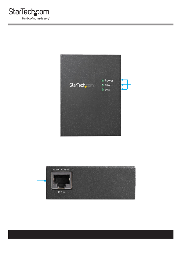
Product Diagram
Splitter
Top View
Input Side View
PoE Input
Port
Power LED
Indicators
To view manuals, videos, drivers, downloads, technical drawings, and more visit www.startech.com/support
1
Page 7

Output Side View
DC Output
Power Port
DC Output
DIP Switch
Ethernet
Data Port
Injector
Top View
Power LED
Indicators
To view manuals, videos, drivers, downloads, technical drawings, and more visit www.startech.com/support
2
Page 8

Input Side View
DC Power
Input Port
Ethernet
Data Port
Output Side View
PoE Output
Port
To view manuals, videos, drivers, downloads, technical drawings, and more visit www.startech.com/support
3
PoE Usage
LED
Indicators
Page 9

Switch Side View
PoE Mode
Switch
Product Information
Package Contents
• PoE Splitter x 1
• PoE Injector x 1
• Universal Power Adapter x 1
• Power Cords (NA/JP, UK, EU, AU) x 4
• DC Plug Cable x 2
• RJ45 Network Cable x 1
• User Manual x 1
To view manuals, videos, drivers, downloads, technical drawings, and more visit www.startech.com/support
4
Page 10

Requirements
For the latest requirements, please visit
www.startech.com/UPOESPLT1G.
Power:
• Available AC Electrical Outlet
Splitter
• Network Device x 1
• Ethernet Cable x 1
Injector
• Network Device x 1
• Ethernet Cable x 2
Installation
Connecting the Splitter to the Injector
Connecting the Injector
1. Toggle the PoE Mode Switch to Standard Mode. See Legacy
for details regarding special applications that require Legacy
Mode to be enabled.
2. Connect an Ethernet Cable to your Network Device.
3. Connect the other end of the Ethernet Cable to the Ethernet
Data Port on the Injector.
4. Connect the Universal Power Adapter to the DC Power Input
Port on the Injector.
5. Connect the other end of the Universal Power Adapter to an
AC Electrical Outlet.
To view manuals, videos, drivers, downloads, technical drawings, and more visit www.startech.com/support
5
Page 11

6. Connect an Ethernet Cable to the PoE Output Port on the
Injector.
Connecting the Splitter
7. Toggle the DC Output Switch to the desired voltage for your
application. Consult the manufacturer’s documentation to
determine the proper input voltage setting for your Network
Device.
Note: Before changing the output voltage, disconnect the
Ethernet Cable from the PoE Input Port on the Splitter.
8. Connect the other end of the Ethernet Cable to the PoE
Input Port on the Splitter.
9. Connect an Ethernet Cable to the Ethernet Data Port on the
Splitter.
10. Connect the other end of the Ethernet Cable to your
Network Device.
11. Connect the appropriate DC Plug Cable for your application
(barrel type M-M or M-N) to the DC Output Power Port on
the Splitter.
12. Connect the other end of the DC Plug Cable to your Network
Device.
Connecting the Splitter Only
1. Connect an Ethernet Cable to your PoE PSE Network Device.
2. Toggle the DC Output Switch to the desired voltage for your
application. Consult the manufacturer’s documentation to
determine the proper input voltage setting for your Network
Device.
To view manuals, videos, drivers, downloads, technical drawings, and more visit www.startech.com/support
6
Page 12

Note: Always disconnect the Ethernet Cable from the PoE
Input Port on the Splitter before changing the output voltage.
3. Connect the other end of the Ethernet Cable to the PoE
Input Port on the Splitter.
4. Connect an Ethernet Cable to the Ethernet Data Port on the
Splitter.
5. Connect the other end of the Ethernet Cable to your non-
PoE Network Device.
6. Connect the appropriate DC Plug Cable for your application
(barrel type M-M or M-N) to the DC Output Power Port on
the Splitter.
7. Connect the other end of the DC Plug Cable to your non-PoE
Network Device.
Connecting the Injector Only
1. Toggle the PoE Mode Switch to Standard Mode. See the
Injector - PoE Mode Switch section for details regarding the
special applications that require Legacy mode to be enabled.
2. Connect an Ethernet Cable to your non-PoE Network Device.
3. Connect the other end of the Ethernet Cable to the Ethernet
Data Port on the Injector.
4. Connect the Universal Power Adapter to the DC Power Input
Port.
5. Connect the other end of the Universal Power Adapter to a
AC Electrical Outlet.
6. Connect an Ethernet Cable to the PoE Output Port on the
Injector.
To view manuals, videos, drivers, downloads, technical drawings, and more visit www.startech.com/support
7
Page 13

7. Connect the other end of the Ethernet Cable to your PoE
Power Delivery Network Device.
Operation
LED Indicators
Splitter LEDs
LED Label Behavior Function
Indicates that that the Splitter is
30W Solid Green
60W+ Solid Green
Power Solid Green
Injector LEDs (Top)
LED Label Behavior Function
Legacy Solid Orange
PoE-in Use Solid Orange Injector is providing PoE power
Power Solid Green
connected to a 2-pair / 30W PoE
Power Source
Indicates that the Splitter is
connected to a 4-pair / Ultra PoE
Power Source
Indicates that the Splitter is
receiving power from a PoE or
Ultra PoE Power Source
Injector is working in *Legacy
Mode
Injector is receiving power from
the Universal Power Adapter
To view manuals, videos, drivers, downloads, technical drawings, and more visit www.startech.com/support
8
Page 14

*Legacy Mode
The legacy detection feature identies connected devices that
do not comply with the IEEE 802.3af/at/bt standard. See Injector
- PoE Mode Switch for details.
Injector LEDs (Side)
LED Label Behavior PoE Usage Indication
O Less than 9W
20W
Blinking Orange 10W to 19W
Solid Orange 20W to 29W
POE
Usage
40W
Blinking Orange 30W to 39W
Solid Orange 40W to 49W
Blinking Orange 50W to 59W
60W+
Solid Orange
Maximum PoE
wattage
Switches
Splitter - DC Output DIP Switch
Warning: Always ensure you are selecting the proper output
voltage. Incorrect voltage selection may cause damage to
your equipment.
The DC Output DIP Switch lets you select the output voltage for
non-PoE Devices. To operate the DC Output Switch, you must
toggle the Switch to the desired output voltage (12V, 19V, or
24V).
To view manuals, videos, drivers, downloads, technical drawings, and more visit www.startech.com/support
9
Page 15

Note: Always disconnect the PoE Input Cable before changing the output voltage.
Injector - PoE Mode Switch
The PoE Mode Switch allows you to switch between Standard
and Legacy PoE modes.
Standard: For all applications that use devices that conform to
the IEEE 802.3af/at/bt standards. Normal use of the Injector will
require this switch setting to be enabled.
Note: Check the manufacturer’s technical documentation
for details regarding the standards followed by the equipment in your application.
Legacy: For all applications that use devices that do not
conform to the IEEE 802.3af/at/bt standards. The Legacy setting
may be required for non-standard PoE Devices, such as some
PTZ cameras.
To view manuals, videos, drivers, downloads, technical drawings, and more visit www.startech.com/support
10
Page 16

Warranty Information
This product is backed by a two-year warranty.
StarTech.com warrants its products against defects in materials and
workmanship for the periods noted, following the initial date of purchase.
During this period, the products may be returned for repair, or replacement with
equivalent products at our discretion. The warranty covers parts and labor costs
only.
StarTech.com does not warrant its products from defects or damages arising
from misuse, abuse, alteration, or normal wear and tear.
Limitation of Liability
In no event shall the liability of StarTech.com Ltd. and StarTech.com USA LLP (or
their ocers, directors, employees or agents) for any damages (whether direct
or indirect, special, punitive, incidental, consequential, or otherwise), loss of
prots, loss of business, or any pecuniary loss, arising out of or related to the use
of the product exceed the actual price paid for the product.
Some states do not allow the exclusion or limitation of incidental or
consequential damages. If such laws apply, the limitations or exclusions
contained in this statement may not apply to you.
To view manuals, videos, drivers, downloads, technical drawings, and more visit www.startech.com/support
11
11
Page 17

Hard-to-nd made easy. At StarTech.com, that isn’t a slogan.
It’s a promise.
StarTech.com is your one-stop source for every connectivity part you need.
From the latest technology to legacy products — and all the parts that bridge
the old and new — we can help you nd the parts that connect your solutions.
We make it easy to locate the parts, and we quickly deliver them wherever they
need to go. Just talk to one of our tech advisors or visit our website. You’ll be
connected to the products you need in no time.
Visit www.startech.com for complete information on all StarTech.com products
and to access exclusive resources and time-saving tools.
StarTech.com is an ISO 9001 Registered manufacturer of connectivity and
technology parts. StarTech.com was founded in 1985 and has operations in the
United States, Canada, the United Kingdom and Taiwan servicing a worldwide
market.
Reviews
Share your experiences using StarTech.com products, including product
applications and setup, what you love about the products, and areas for
improvement.
StarTech.com Ltd.
45 Artisans Cres.
London, Ontario
N5V 5E9
Canada
FR: fr.startech.com
DE: de.startech.com
StarTech.com LLP
2500 Creekside Pkwy.
Lockbourne, Ohio
43137
U.S.A.
ES: es.startech.com
NL: nl.startech.com
StarTech.com Ltd.
Unit B, Pinnacle
15 Gowerton Rd.,
Brackmills
Northampton
NN4 7BW
United Kingdom
IT: it.startech.com
JP: jp.startech.com
To view manuals, videos, drivers, downloads, technical drawings, and more visit www.startech.com/support
 Loading...