

Page 1
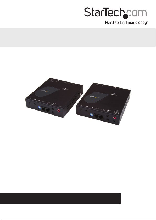
HDMI® Over IP Extender Kit - 4K
ST12MHDLAN4K
FR: Guide de l’utilisateur - fr.startech.com
DE: Bedienungsanleitung - de.startech.com
ES: Guía del usuario - es.startech.com
NL: Gebruiksaanwijzing - nl.startech.com
PT: Guia do usuário - pt.startech.com
IT: Guida per l’uso - it.startech.com
For the latest information, technical specications, and support for
this product, please visit www.StarTech.com/ST12MHDLAN4K.
Manual Revision: 10/26/2017
*actual product may vary from photos
Page 2

FCC Compliance Statement
This equipment has been tested and found to comply with the limits for a Class B digital
device, pursuant to part 15 of the FCC Rules. These limits are designed to provide reasonable
protection against harmful interference in a residential installation. This equipment
generates, uses and can radiate radio frequency energy and, if not installed and used in
accordance with the instructions, may cause harmful interference to radio communications.
However, there is no guarantee that interference will not occur in a particular installation. If
this equipment does cause harmful interference to radio or television reception, which can
be determined by turning the equipment o and on, the user is encouraged to try to correct
the interference by one or more of the following measures:
• Reorient or relocate the receiving antenna.
• Increase the separation between the equipment and receiver.
• Connect the equipment into an outlet on a circuit dierent from that to which the
receiver is connected.
• Consult the dealer or an experienced radio/TV technician for help
This device complies with part 15 of the FCC Rules. Operation is subject to the following
two conditions: (1) This device may not cause harmful interference, and (2) this device must
accept any interference received, including interference that may cause undesired operation.
Changes or modications not expressly approved by StarTech.com could void the user’s
authority to operate the equipment.
Industry Canada Statement
This Class B digital apparatus complies with Canadian ICES-003.
Cet appareil numérique de la classe [B] est conforme à la norme NMB-003 du Canada.
CAN ICES-3 (B)/NMB-3(B)
Use of Trademarks, Registered Trademarks, and other Protected Names and Symbols
This manual may make reference to trademarks, registered trademarks, and other
protected names and/or symbols of third-party companies not related in any way to
StarTech.com. Where they occur these references are for illustrative purposes only and do not
represent an endorsement of a product or service by StarTech.com, or an endorsement of the
product(s) to which this manual applies by the third-party company in question. Regardless
of any direct acknowledgement elsewhere in the body of this document, StarTech.com hereby
acknowledges that all trademarks, registered trademarks, service marks, and other protected
names and/or symbols contained in this manual and related documents are the property of
their respective holders.
Instruction manual
Page 3

Table of Contents
Introduction ......................................................................................................... 1
Packaging contents .................................................................................................................................. 1
System requirements ...............................................................................................................................1
Product diagram ................................................................................................. 2
Transmitter Unit .........................................................................................................................................2
Receiver Unit ............................................................................................................................................... 3
Installation ............................................................................................................ 4
Preparing your site....................................................................................................................................4
Hardware installation .............................................................................................................................. 4
Software installation ................................................................................................................................ 6
Technical support ...............................................................................................7
Warranty information .......................................................................................7
Instruction manual
i
Page 4

Introduction
Packaging contents
• 1 x HDMI over IP transmitter
• 1 x HDMI over IP receiver
• 2 x universal power adapters (NA, EU, UK, ANZ)
• 2 x mounting brackets
• 2 x CAT5 cables
• 2 x RJ11 to RS232 adapters
• 2 x RJ11 cables
• 1 x plastic screwdriver
• 1 x quick-start guide
System requirements
• An HDMI video source with cabling such as a computer or Blu-ray™ player
• An HDMI display with cabling such as televisions or projectors (one for each
receiver)
• A run of Network cabling for the transmitter and each receiver
Instruction manual
1
Page 5
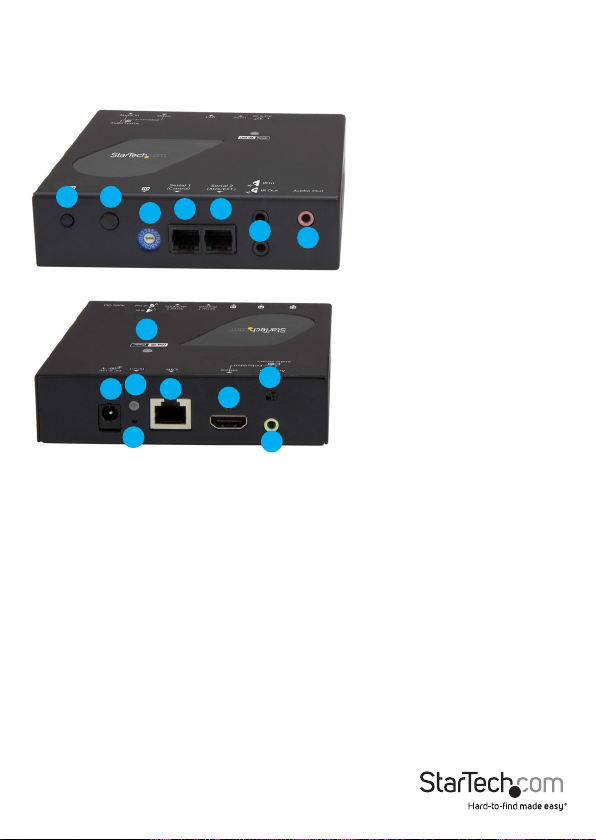
Product diagram
Transmitter unit
Front view
12
4 5
3
6
7
Back view
15
9
8
11
10
1. Function 1 button
2. Function 2 button
3. Dip rotary switch
4. Serial control port (not active)*
5. Serial extension (RS-232 signal)
6. Infrared (in) and (out) ports
7. Audio out port **
8. DC 9-12V power jack
* Serial control port is not active. To control the ST12MHDLAN4K download
our free mobile application. (see Page 6).
**Audio out port is not functional in video wall or point to multi-point
congurations.
14
12
13
9. Network status LED
10. Reset button
11. LAN port (RJ-45)
12. HDMI input port (audio/video)
13. Analog audio source port (3.5 mm stereo)
14. Audio source selection switch
15. Link and power LED
Instruction Manual
2
Page 6
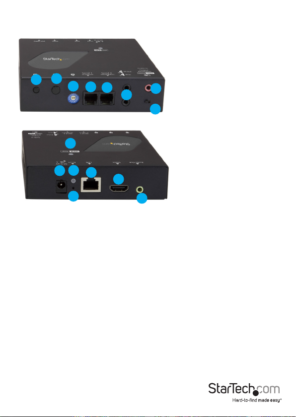
Receiver unit
Front view
1
2
Back view
9
Additional receiver units sold separately:
StarTech.com SKU: ST12MHDLAN4R
3
4
5
7
6
8
15
10
12
13
11
14
1. Function 1 button
2. Function 2 button
3. Dip rotary switch
4. Serial control (not active)*
5. Serial extension (for extending RS-232 signal)
6. Infrared (in) and (out) ports
7. Audio in port**
8. Video resolution selection switch
9. DC 9-12V power jack
10. Network status LED
11. Reset button
12. LAN port (RJ-45)
13. HDMI output port (audio/video)
* Serial control port is not active. To control the
ST12MHDLAN4K download our free mobile
application. (see Page 6).
**Audio in port is not functional in Video Wall or
Point to Multi-Point congurations.
14. Analog audio output (3.5 mm stereo)
15. Link and power LED
Instruction manual
3
Page 7

Installation
Preparing your site
Note: The HDMI extender kit lets you extend your 4K30 video signals over a Gigabit
LAN network, beyond the typical cable length restriction of 330 ft. (100m) of Gigabit
network portals.
Refer to the manufacturer of the network equipment to determine the length
restriction and to ensure the transmitter unit and receiver unit(s) are all within the
restricted range of the nearest network portal.
Note: Ensure the transmitter unit, and receiver unit(s) are all situated near AC electrical
outlets.
1. Determine where the local video source will be located and set up the transmitter
near that location.
2. Determine where the remote display will be located and set up the receiver near
that location.
3. (Optional) If you’re using additional displays, determine where they will be located
and set the additional receiver unit(s) near that location.
Hardware installation
Video wall or point to multi-point installation with a Gigabit LAN network.
1. Install the transmitter unit.
a) Connect your video source to the transmitter’s video input port.
b) Connect the transmitter’s DC 9-12V power jack to an AC electrical outlet, using one
of the included power adapters.
c) (Optional) If you intend to add a separate 3.5 mm audio source that can be
embedded into the HDMI signal and selected as the audio source, connect a 3.5
mm audio cable to your audio source device and to the transmitter’s analog audio
source port.
2. Install the receiver unit(s).
a) Connect a display to the receiver unit’s video output port using an HDMI cable.
b) Connect the receiver unit’s power jack to an AC electrical outlet, using one of the
included power adapters.
c) (Optional) If you are using additional ST12MHDLAN4R receivers (sold separately),
repeat steps [a) through b)] for each additional receiver.
Note: The rotary dip switches on the transmitter and each receiver connected to the
network must be set in the same position for the devices to communicate.
Instruction manual
4
Page 8

3. Connect the devices to a Gigabit LAN network
a) Connect an RJ-45 terminated Cat5e or Cat6 Ethernet cable to the LAN port on the
transmitter unit, and to each of the receiver units.
b) Connect the other end of the Cat5e or Cat6 cable to a Gigabit LAN hub, router or
switch.
Note: Your router must support IGMP snooping and Jumbo frames. Please refer to your
network switch or router documentation to ensure IGMP snooping is supported and
enabled.
b) Connect the other end of the Cat5e or Cat6 cable to a Gigabit LAN hub, router or
switch.
4. Verify that the image from your video source appears on video display(s) attached
to the receiver unit(s).
HDMI over IP receivers
HDMI displays
Gigabit network switch
HDMI over IP transmitter
HDMI video source
(Additional receiver units sold separately, StarTech.com SKU: ST12MHDLAN4R)
Instruction Manual
5
Page 9

5. (Optional) Connect external 3.5 mm speakers to your remote receiver(s) Analog
audio output port.
6. Select your audio source.
a) If you’d like the remote device(s) (external speakers and HDMI displays) to output
the native HDMI audio that’s on your HDMI source, set the transmitter’s audio
selection switch to Video.
b) If you’d like to use the 3.5mm audio source that you connected to the Analog audio
source port, set the transmitter’s audio selection switch to Audio In.
Note: Both the HDMI output port and the Analog audio output will output whatever
audio source is selected.
Software installation
The HDMI distribution kit features video control software that helps you manage your
IP video distribution and video wall conguration. The software is available on iOS
for your iPhone or iPad, Android™ for your smartphone or tablet, and for the Google
Chrome™ browser.
To install the software:
1. Visit http://www.StarTech.com/ST12MHDLAN4K, using the device you intend to
install software on.
2. Under the overview tab, select the link for the store that corresponds with your
device.
Select the option to download and install the software from the store page.
3. Open the software, to verify that it has installed correctly.
Instruction Manual
6
Page 10

Software operation
Connecting your transmitters and receivers to the software
Note: To ensure the application functions properly, your router must support IGMP
snooping. Please refer to your network switch or router documentation to ensure IGMP
snooping is supported and enabled.
1. Ensure your computer, smartphone or tablet that the software has been installed
on is connected to the same network as your transmitter(s) and receiver(s), and
launch the application.
2. Once launched, the application will open on the Devices tab, and will
Instruction Manual
7
Page 11

automatically search for transmitters and receivers on your network and list them
within the Devices tab.
Note: you can re-initiate the device search, by selecting the refresh button in the
top right-hand corner of the Devices tab.
Instruction Manual
8
Page 12

3. By default, each video device will have an IP address in the range of 169.254.x.x
with a subnet mask of 255.255.0.0.
Each transmitter and receiver must have an IP address in the same range, and have
an identical subnet mask as each other, and the tablet, smartphone or computer
you have the software installed on.
For example: If your transmitter has an IP address of 169.254.10.10 with a
subnet mask of 255.255.0.0.
You must ensure the tablet, smartphone or computer you have the software
installed on and each receiver has an IP address that starts with 169.254.x.x
(with a varying last two digits represented here by xx) and a subnet mask of
255.255.0.0.
To adjust the IP address and subnet mask of your transmitter(s) and
receiver(s):
a. Select the transmitter or receiver you’d like to adjust from the Devices tab.
Instruction Manual
9
Page 13

b. Click the edit Icon listed in the IP address section.
c. Select Static IP and type an IP address and mask for the device.
Or
Select DHCP and your network automatically assign an IP address and mask to
Instruction Manual
10
Page 14

Note: DHCP must be enabled on your network to automatically assign an IP address
and mask in that range.
Switching your remote displays between video sources
1. Once the application is launched, select the Switches tab.
2. A list of each connected receiver will be displayed with all available transmitters
displayed beside them. The transmitter that is currently selected for each receiver
will be highlighted in yellow.
Instruction Manual
11
Page 15

Note: if the receiver is part of a video wall it will be indicated with a button that
lists the wall conguration and the location of the receiver.
Instruction Manual
12
Page 16

3. To assign a video source, or change your video source, select the transmitter listed
next to your receiver that you’d like to display.
4. The transmitter will turn yellow and your video source will switch on the remote
display.
Note: If a receiver that was part of a video wall conguration is altered, that
display will no longer be part of the video wall conguration.
Conguring your remote displays
for a video wall application
1. Once the application is launched, select the Walls tab.
2. Select the + icon to launch a wizard that will walk you through your video wall
creation.
3. The rst page in the wizard enables you to specify the walls name as well as the
number of rows and columns you would like to use in your video wall. Each row
and column will represent a display in your video wall. Type your preferred name
and specify the number of rows and columns, then click next.
Instruction Manual
13
Page 17

Note: a Wall Name will be listed by default, once you type a new name the default
name will be overwritten.
4. The next page in the wizard will create an example of the video wall with the
number of rows and columns you specied.
You will need to use this example to specify which receivers are represented
within your video wall conguration. Select the receiver from the video wall
example to display a list of all connected receivers, then choose the receiver that
corresponds with the proper location within your video wall conguration.
Instruction Manual
14
Page 18

Note: If you would like to see the receiver device name on each screen, so you can
easily identify which display is connected to each receiver, please select the show
device names on screen switch. This can be deactivated once you have identied
your displays.
5. (Optional) If the displays in your video wall conguration have large bezels or
empty space between them, you can scale the image on the displays to create a
more natural, seamless look by specifying the bezel compensation. Click the Bezel
Compensation button to open the window.
Instruction Manual
15
Page 19

On the bezel compensation window, enter the following measurements in
millimeters (mm): screen width of each display (ScreenX), screen height of each
display (ScreenY), total width of each display (DisplayX) and total height of each
display (DisplayY). Then click the Save button.
6. The wizard is now complete and your created video wall conguration will appear
on the Walls tab.
You can select or switch your video source for each created video wall
conguration clicking transmitters listed below each created video wall
conguration.
Instruction Manual
16
Page 20

Notes:
• The display indicators will show the status of the current wall. Blue indicates that the
display is active, Grey indicates it is being used for another wall or switch.
• You can adjust the settings dened for each video wall conguration or delete your
video wall conguration by clicking the arrow next to each video wall.
Advanced operation and help
You can access the software menu from any screen by clicking the menu icon in the
top right-hand corner of the application.
From the menu you can access each of the options below.
Instruction Manual
17
Page 21

Help:
Lists information and walk-throughs regarding operation of the application.
Device Search Mode:
Enables you to dene your preferred method of transmitter and receiver identication
over your network that the software uses. You can choose between two methods of
identication: Multicast DNS or Target IP for your transmitters and receivers.
Multicast DNS: is the default setting and will search automatically for devices over
the network.
Target IP: is an advanced setting that enables you to specify an IP address that
the remote devices are set to in order for the software to identify them. This is a
good option if you’d like multiple set ups with dierent displays and transmitters on
dierent subnets and IP address ranges.
Clear All Settings:
Restores your software to default settings.
Demo Mode:
Creates a virtual environment with multiple transmitters and receivers that enables
you to congure a virtual setup without connected transmitters and receivers to test
the functionality of the software.
Instruction Manual
18
Page 22

Technical support
StarTech.com’s lifetime technical support is an integral part of our commitment to
provide industry-leading solutions. If you ever need help with your product, visit
www.startech.com/support and access our comprehensive selection of online tools,
documentation, and downloads.
For the latest drivers/software, please visit www.startech.com/downloads
Warranty information
This product is backed by a two-year warranty.
StarTech.com warrants its products against defects in materials and workmanship
for the periods noted, following the initial date of purchase. During this period,
the products may be returned for repair, or replacement with equivalent
products at our discretion. The warranty covers parts and labor costs only.
StarTech.com does not warrant its products from defects or damages arising from
misuse, abuse, alteration, or normal wear and tear.
Limitation of liability
In no event shall the liability of StarTech.com Ltd. and StarTech.com USA LLP (or their
ocers, directors, employees or agents) for any damages (whether direct or indirect,
special, punitive, incidental, consequential, or otherwise), loss of prots, loss of business,
or any pecuniary loss, arising out of or related to the use of the product exceed the
actual price paid for the product. Some states do not allow the exclusion or limitation
of incidental or consequential damages. If such laws apply, the limitations or exclusions
contained in this statement may not apply to you.
Instruction manual
19
Page 23

Hard-to-nd made easy. At StarTech.com, that isn’t a slogan. It’s a promise.
StarTech.com is your one-stop source for every connectivity part you need. From
the latest technology to legacy products — and all the parts that bridge the old and
new — we can help you nd the parts that connect your solutions.
We make it easy to locate the parts, and we quickly deliver them wherever they need
to go. Just talk to one of our tech advisors or visit our website. You’ll be connected to
the products you need in no time.
Visit www.startech.com for complete information on all StarTech.com products and
to access exclusive resources and time-saving tools.
StarTech.com is an ISO 9001 Registered manufacturer of connectivity and technology
parts. StarTech.com was founded in 1985 and has operations in the United States,
Canada, the United Kingdom and Taiwan servicing a worldwide market.
 Loading...