

Page 1

1 Port RS232 Serial over IP Ethernet Device
Server
Actual product may vary from photos
User Manual
SKU#: NETRS2321P
For the latest information and specications visit
www.startech.com/NETRS2321P
Manual Revision: 09/19/2019
Page 2

Compliance Statements
FCC Compliance Statement
This equipment has been tested and found to comply with the limits for a
Class A digital device, pursuant to Part 15 of the FCC rules. These limits are
designed to provide reasonable protection against harmful interference when
the equipment is operated in a commercial environment. This equipment
generates, uses and can radiate radio frequency energy and, if not installed and
used in accordance with the instruction manual, may cause harmful interference
to radio communications. Operation of this equipment in a residential area is
likely to cause harmful interference in which case the user will be required to
correct the interference at his own expense.
This device complies with part 15 of the FCC Rules. Operation is subject to the
following two conditions: (1) This device may not cause harmful interference,
and (2) this device must accept any interference received, including interference
that may cause undesired operation.
Changes or modications not expressly approved by StarTech.com could void
the user’s authority to operate the equipment.
Industry Canada Statement
This Class A digital apparatus complies with Canadian ICES-003.
Cet appareil numérique de la classe [A] est conforme à la norme NMB-003 du
Canada.
CAN ICES-3 (A)/NMB-3(A)
Use of Trademarks, Registered Trademarks, and other
Protected Names and Symbols
This manual may make reference to trademarks, registered trademarks, and
other protected names and/or symbols of third-party companies not related in
any way to StarTech.com. Where they occur these references are for illustrative
purposes only and do not represent an endorsement of a product or service
by StarTech.com, or an endorsement of the product(s) to which this manual
applies by the third-party company in question. Regardless of any direct
acknowledgement elsewhere in the body of this document, StarTech.com
hereby acknowledges that all trademarks, registered trademarks, service marks,
and other protected names and/or symbols contained in this manual and
related documents are the property of their respective holders.
To view manuals, videos, drivers, downloads, technical drawings, and more visit www.startech.com/support
1
Page 3

Safety Statements
Safety Measures
• Wiring terminations should not be made with the product and/or electric
lines under power.
• Cables (including power and charging cables) should be placed and routed
to avoid creating electric, tripping or safety hazards.
Mesures de sécurité
• Les terminaisons de câblâge ne doivent pas être eectuées lorsque le produit
et/ou les câbles électriques sont sous tension.
• Les câbles (y compris les câbles d’alimentation et de chargement) doivent
être placés et acheminés de façon à éviter tout risque électrique, de chute ou
de sécurité
安全対策
• 電源が入っている状態の製品または電線の終端処理を行わないでくださ
い。
• ケーブル(電源ケーブルと充電ケーブルを含む)は、適切な配置と引き回し
を行い、電気障害やつまづきの危険性など、安全上のリスクを回避するよう
にしてください 。
Misure di sicurezza
• I terminiali dei li elettrici non devono essere realizzate con il prodotto e/o le
linee elettriche sotto tensione.
• I cavi (inclusi i cavi di alimentazione e di ricarica) devono essere posizionati
e stesi in modo da evitare pericoli di inciampo, rischi di scosse elettriche o
pericoli per la sicurezza.
Säkerhetsåtgärder
• Montering av kabelavslutningar får inte göras när produkten och/eller
elledningarna är strömförda.
• Kablar (inklusive elkablar och laddningskablar) ska dras och placeras på så
sätt att risk för snubblingsolyckor och andra olyckor kan undvikas.
To view manuals, videos, drivers, downloads, technical drawings, and more visit www.startech.com/support
2
Page 4

Table of Contents
Compliance Statements ........................................................................1
Safety Statements ..................................................................................2
Product Diagram ....................................................................................5
Top View .......................................................................................................................................................5
Rear View ...................................................................................................................................................... 6
RJ45 Pin Assignment ................................................................................................................................ 7
RS-232 DB9 Pin Assignment .................................................................................................................. 8
Product Information ..............................................................................9
Package Contents ..................................................................................................................................... 9
Installation ..............................................................................................9
DIN Rail Mounting ..................................................................................10
Load Default Settings/System Reset Button......................................10
Load Default Settings .............................................................................................................................. 10
System Reset ............................................................................................................................................... 10
Broadcast Search ....................................................................................................................................... 10
Using the Web Console .........................................................................11
Accessing the Web Console................................................................................................................... 11
Changing/Setting a Login ID and Password....................................................................................11
Conguring System Network Settings .............................................................................................. 12
System Status ............................................................................................................................................. 14
Load Default Setting ................................................................................................................................ 14
To view manuals, videos, drivers, downloads, technical drawings, and more visit www.startech.com/support
3
Page 5

Firmware Update ....................................................................................15
Conguring TCP Mode ..........................................................................16
Conguring UDP Mode .........................................................................18
UART .........................................................................................................20
Resetting the Device ..............................................................................23
Virtual COM Software Operation .........................................................23
Installing the Virtual COM Software ................................................................................................... 23
Conguration the Virtual COM Software ..........................................................................................25
Setting Up COM Mapping ...................................................................................................................... 27
TCP/UDP Settings ...................................................................................29
LED Indicators .........................................................................................31
To view manuals, videos, drivers, downloads, technical drawings, and more visit www.startech.com/support
4
Page 6

Product Diagram
Top View
1
4
3
2
1 LEDs
2 RS-232 DB9 Serial Port
3 Wall Mount Screw Hole
4 DIN Rail Screw Hole
To view manuals, videos, drivers, downloads, technical drawings, and more visit www.startech.com/support
5
Page 7

Rear View
1 32
1 RJ45 Port
2 Load Default/Reset Button
3 DC Jack
To view manuals, videos, drivers, downloads, technical drawings, and more visit www.startech.com/support
6
Page 8

RJ45 Pin Assignment
Pin Description
1 TX+
2 TX-
3 RX+
6 RX-
To view manuals, videos, drivers, downloads, technical drawings, and more visit www.startech.com/support
7
Page 9

RS-232 DB9 Pin Assignment
NOTE: This serial device server performs as a DTE device.
Pin Name IO
1 DCD Input
2 RD Input
3 TD Output
4 DTR Output
5 GND
6 DSR Input
7 RTS Output
8 CTS Input
To view manuals, videos, drivers, downloads, technical drawings, and more visit www.startech.com/support
8
Page 10

Product Information
Package Contents
• Serial over IP Device Server x 1
• Universal Power Adapter (NA/UK/EU/AU) x 1
• User Manual x 1
• DIN Rail Kit x 1
Installation
1. Plug in the power adapter and connect the RJ45 interface to
your LAN.
NOTE: Alternatively, you can also use a crossover cable to
connect the NETRS2321P directly to your system for the initial
conguration.
2. Press and hold the load default button for more than 3
seconds and less than 10 seconds, then release it. This will
return the serial device server to factory default and it will
respond to the IP address 10.1.1.1.
3. Congure the PC to the same IP domain.
4. Open a web browser and connect to http://10.1.1.1 to
open the conguration interface. The default login ID will be
“admin” and the password will be “admin”.
5. Once logged in, you will have access to all conguration
settings including the ability to change the IP address for the
device server.
To view manuals, videos, drivers, downloads, technical drawings, and more visit www.startech.com/support
9
Page 11

DIN Rail Mounting
• Attach the included DIN Rail brackets (one per side) using the
provided screws to the top DIN Rail screw hole (marked in the
above diagram), and clip to your DIN Rail
Load Default Settings/System Reset Button
Load Default Settings
• Press and hold this button for more than 3 seconds, then
release to load the factory default settings.
IP address: 10.1.1.1
Subnet Mask: 255.0.0.0
Login ID / Password: admin
System Reset
• Press and hold this button for more than 10 seconds, then
release to reboot the device (maintains conguration
settings)
Broadcast Search
• The Broadcast Search function is used to locate all
NETRS2321P devices that are connected to the same LAN
as your computer. Since the Broadcast Search function
searches by MAC address and not IP address, all NETRS2321P
connected to the LAN will be located, regardless of whether
or not they are part of the same subnet as the host.
NOTE: Broadcast packet packets are not passed through a
router. The VCom utility can only be used to monitor devices
in the same segment of the LAN.
To view manuals, videos, drivers, downloads, technical drawings, and more visit www.startech.com/support
10
Page 12
Using the Web Console
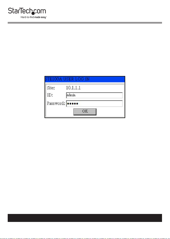
Accessing the Web Console
1. Navigate to an web page and enter the IP Address on the
NETRS2321P device in the Address Bar and press Enter
(default IP Address = 10.1.1.1).
2. The Login screen will appear.
Login in Screen
3. Enter an ID and Password and press the OK button (default
ID = admin and password = admin).
4. The Home screen will appear.
Changing/Setting a Login ID and Password
1. From the Home screen, click the Administrator link on the
left-hand side of the screen.
2. From the drop down menu select the Authentication link.
3. The Authentication screen will appear.
To view manuals, videos, drivers, downloads, technical drawings, and more visit www.startech.com/support
11
Page 13

Authentication Screen
4. Enter a new login ID and Password (The ID and Password
must be a maximum of 15 characters and alphanumeric).
5. Press Update button to store the data.
6. Reset the device to for the new ID and Password to take
eect.
Conguring System Network Settings
1. From the Home screen, click the Administrator link on the
left-hand side of the screen.
2. From the drop down menu select the System IP link.
3. The System IP screen will appear.
To view manuals, videos, drivers, downloads, technical drawings, and more visit www.startech.com/support
12
Page 14
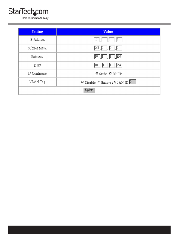
System IP Screen
4. On the System IP screen, you can adjust the network
conguration settings by selecting the Static radio button on
the IP Congure eld,
5. If the IP Congure eld is set to DHCP mode, all other
settings will be ignored, and the IP address will be assigned
by DHCP server after resetting the device.
6. Press the Update button to apply the network changes and
reset the default for the changes to take place.
To view manuals, videos, drivers, downloads, technical drawings, and more visit www.startech.com/support
13
Page 15

System Status
1. From the Home screen, click the Administrator link on the
left-hand side of the screen.
2. From the drop down menu select the System Settings link.
3. The System Settings screen will appear.
System Settings Screen
4. On the System Settings screen, you can display the system
Kernel rmware version and MAC Address.
5. You can also adjust the device alias (Target Name) and Idle
timeout settings. The Target Name eld allows a Max of 12
alphanumeric characters, including underscore, and dash.
6. Press the Update button to store the Target Name data, and
reset the device for the changes to take eect.
Load Default Setting
1. From the Home screen, click the Administrator link on the
left-hand side of the screen.
2. From the drop down menu select the Load Default Settings
link.
3. The Load Default Settings screen will appear.
To view manuals, videos, drivers, downloads, technical drawings, and more visit www.startech.com/support
14
Page 16

4. On the Load Default Settings screen, you can load and store
the factory default settings into EEPROM.
NOTE: Network settings and MAC address will not be
changed.
5. Press Load button to load default settings.
6. Reset the device for the changes to take eect.
Firmware Update
On this page, you can update the rmware via Ethernet.
Note: Pressing the ‘Load’ button will immediately erase the
ash with no further warning
1. From the Home screen, click the Administrator link on the
left-hand side of the screen.
2. From the drop down menu select the Load Default Settings
link.
3. The Load Default Settings screen will appear.
1. Press the Load button to erase ash.
2. Wait for erase process to complete.
3. There are two methods to do the Firmware Update action
(TFTP or Web):
Note: Please avoid loss of network connection, power or
other interruption during the rmware upgrade procedure.
• Web:
• Please type in or browse the target image le in the input
To view manuals, videos, drivers, downloads, technical drawings, and more visit www.startech.com/support
15
Page 17

eld, and then press “update” button to continue.
• TFTP:
• Use Windows Command Prompt window to run the tftp
client program.
• Syntax: tftp -i 10.1.1.1 put FILE_DIRECTORY\FILENAME.bin
• The rmware update should take about 45 seconds to
complete.
• If the update process somehow goes wrong (like power
failure), please connect to http://10.1.1.1 to try and restart
the process (you may have to reset the device rst).
Conguring TCP Mode
Note: When TCP mode is set to Server or Client mode, the
UDP mode will be disabled automatically. When UDP mode
is enabled, the TCP mode will be disabled automatically.
1. From the Home screen, click the TCP Mode link on the left-
hand side of the screen.
2. The TCP Mode screen will appear.
To view manuals, videos, drivers, downloads, technical drawings, and more visit www.startech.com/support
16
Page 18

TCP Mode Screen
3. The following settings can be congured:
• Telnet Server/Client: Set the device to be a Telnet Server.
In server mode, the Telnet port listens and waits for a
host or other client to make a connection. In this case the
Ethernet connected device is the client.
• Reverse Telnet: Reverse Telnet works the same as Telnet
Server mode. The Telnet port is listens for a connection
after booting up. If you encounter errors when using some
Telnet clients, such as the Microsoft interpretation of Telnet
for Windows XP you can try the connection using Reverse
Telnet mode.
• CLI Mode: The Command Line Interface (CLI) allows user
to congure and control NETRS2321P directly through the
UART interface.
To view manuals, videos, drivers, downloads, technical drawings, and more visit www.startech.com/support
17
Page 19

Note: CLI mode is only available when NETRS2321P is in TCP
Server Mode.
• Port Number: This assigns the TCP server port number
that the server will listen on for connecting clients (Only
for TCP Server Mode).
• Remote Server IP Address: When in Client mode, this
device will automatically try to connect to the remote TCP
server with this IP address.
• Client Mode Inactive Timeout: When in Client mode,
this parameter sets the time that device will maintain a
connection until timeout, if there is no data transfer over
the connection. After disconnecting, the device will try to
build a new connection again immediately.
• Server Mode Protect Timeout: When in Server mode,
this parameter sets the time that device will maintain a
connection until timeout, if there is no data transfer over
the connection. Once disconnected, only a Client can
initiate a new connection to the Server.
4. Once you have completed making changes, press the
Update button to store the data.
5. Reset the device for the changes to take eect.
Conguring UDP Mode
1. From the Home screen, click the UDP Mode link on the left-
hand side of the screen.
2. The UDP Mode screen will appear.
To view manuals, videos, drivers, downloads, technical drawings, and more visit www.startech.com/support
18
Page 20

UDP Mode Screen
3. The following settings can be congured:
• Mode:
• Disabled: When UDP mode is enabled, TCP mode will
be disabled automatically. In UDP mode, the Local Port
will be assigned to this device. You can list the remote
connection IP and Port for up to 10 remote devices.
• Listen: When in UDP Listen mode, it can only receive
remote UDP data.
• Normal: When in UDP Normal mode, it can both receive
and send UDP data to
remote units.
• Local Port: Assign the UDP port that this unit listens on.
To view manuals, videos, drivers, downloads, technical drawings, and more visit www.startech.com/support
19
Page 21

• Remote Address: The remote address table allows users
to set several remote site IP addresses and ports. When
sending data, the device will send UDP data to the IP
addresses in the table.
4. Once you have completed making changes, press the
Update button to store the data.
5. Reset the device for the changes to take eect.
UART
UART or Universal Asynchronous Receiver Transmitter refers to
the RS-232 serial port of the device. All of the port settings can
be modied from the UDP screen.
1. From the Home screen, click the UART link on the left-hand
side of the screen.
2. The UART Mode screen will appear.
To view manuals, videos, drivers, downloads, technical drawings, and more visit www.startech.com/support
20
Page 22

UART Screen
3. The following settings can be congured:
• Baud Rate: Set the baud rate of UART interface. The
NETRS2321P supports 110, 300, 1200, 2400, 4800, 9600,
19200, 38400, 57600, 115200 and 230400bps baud rates.
• Character Bits: Set the number of data length of UART
interface. The NETRS2321P supports character bits of 5, 6,
7, or 8 bits.
To view manuals, videos, drivers, downloads, technical drawings, and more visit www.startech.com/support
21
Page 23

• Parity Type: Set the parity of UART interface. The
NETRS2321P supports parity settings of Odd, Even, Space,
Mark or none.
• Stop Bit: Set the stop bit length of UART interface. The
NETRS2321P supports 1, 1.5 or 2 stop bits.
• Hardware Flow Control: Set the ow control mode of
UART interface as enabled or as none.
• UART Memory Overow Count: Shows the number of
overow bytes in network buer.
• UART FIFO Overow Count: Shows the number of
overows counted in the UART RX buer.
• Delimiter: This sets the Character 1 and/or Character 2 to
be used as the delimiter. When sending data from serial to
TCP the data is rst stored in the cache. When set, not until
the value of character 1 or 2 is received from the serial side
is the data released from the cache and sent to TCP.
• Silent time: If there is no data sent or received for the
number of milliseconds specied the connection is
dropped.
• Drop Character: drops the delimiter character of the
serial port when sending to TCP, (the receiver doesn’t
display the character).
4. Once you have completed making changes, press the
Update button to store the data.
5. Reset the device for the changes to take eect.
To view manuals, videos, drivers, downloads, technical drawings, and more visit www.startech.com/support
22
Page 24

Resetting the Device
1. From the Home screen, click the Restart link on the left-hand
side of the screen.
2. The UART Mode screen will appear.
3. Press the Reset button to rest the NETRS2321P.
Virtual COM Software Operation
The Virtual Com application lets you install and congure your
NETRS2321P easily over the network. Five function groups are
provided to ease the installation process, allow COM mapping,
and provide monitoring and IP location server functions.
Installing the Virtual COM Software
1. Using a web browser, navigate to www.startech.com/
NETRS2321P.
2. On the Product page, click the Support tab located in the
middle of the screen.
3. In the Drivers and Downloads section, click on the driver link
that corresponds with the operating system running on the
host computer.
4. When the download is complete, right-click the zip folder
and select Extract All.
5. In the list of extracted les, right-click the vcomsetup.exe le
and select Run as Administrator and follow the on-screen
prompts to complete the installation.
To view manuals, videos, drivers, downloads, technical drawings, and more visit www.startech.com/support
23
Page 25

6. When the VCOM software has been downloaded, navigate to
the Start Menu or Desktop and select VCOM.
7. The Main screen will appear.
Main Screen
8. Select the Search button to locate all Devices that are
connected to the same LAN as your computer. Since the
Search function searches by MAC address and not IP address,
all connected devices to the LAN will be located, regardless
of whether or not they are part of the same subnet as the
host.
To view manuals, videos, drivers, downloads, technical drawings, and more visit www.startech.com/support
24
Page 26

Conguration the Virtual COM Software
1. From the Main screen, select the device you would like to
adjust and click the Congure button.
Main Screen
2. An Authorization screen will appear, you will be prompted to
enter your User ID and Password (Default: admin / admin).
Authorization Screen
3. Click the Update button.
To view manuals, videos, drivers, downloads, technical drawings, and more visit www.startech.com/support
25
Page 27

4. The Congure Dialog screen will appear.
Congure Dialog Screen
5. The port IP and Port number can be congured.
6. Select the OK button to save changes.
To view manuals, videos, drivers, downloads, technical drawings, and more visit www.startech.com/support
26
Page 28

Setting Up COM Mapping
1. From the Main screen, select the Com Mapping link from the
left-side of the screen.
Main Screen
2. The COM Mapping screen will appear.
COM Mapping Screen
To view manuals, videos, drivers, downloads, technical drawings, and more visit www.startech.com/support
27
Page 29

3. Click the Add button.
4. The Add VCON screen will appear.
Add VCON Screen
5. Fill out the following elds to add a VCON:
• TCP/UDP: Choose a network protocol.
• Server/Client: Choose either Server or Client.
• IP Address: Enter the IP Address.
• Local Port: Enter a local port number.
• COM: Enter a Virtual COM port number.
• Remote Port: Enter a remote port number.
6. Click OK to create the COM Mapping
To view manuals, videos, drivers, downloads, technical drawings, and more visit www.startech.com/support
28
Page 30

TCP/UDP Settings
Depending on the protocol you are using, the options below
will enable/disable automatically as applicable.
Server/Client (TCP Mode Only)
• Set the device to be a Telnet Server. In server mode, the
Telnet port listens and waits for a host or other client to make
a connection. In this case the Ethernet connected device is
the client.
• Set the device to be a Telnet Client. In the case the Ethernet
connected device is the Telnet server or other NETRS2321P in
server mode.
IP Address
• Depending on your selections above, there are one of three
scenarios:
• TCP Server - Disabled
• TCP Client - Remote Server Address
• UDP - Remote Target Address
Local Port
• Assigns the local port for the device to listen on TCP Server –
Assigns the TCP server port number that the server will listen
on TCP Client – Disabled UDP – Assign the UDP port that this
unit listens on.
COM
• Assign the desired virtual COM port number
To view manuals, videos, drivers, downloads, technical drawings, and more visit www.startech.com/support
29
Page 31

Remote Port
• TCP Server – Disabled
• TCP Client – Assign the remote TCP port you wish to
communicate on.
• UDP – Assign the remote UDP port you wish to communicate
on
Enable Control Connection (TCP Server or Client Only)
• Enables/Disables control of the serial device on a remote
network. Using the IP address and port number allows the
user to gain control of the receiver from a remote location
when this is enabled.
Second(s) for Reconnection Interval
• Dictates the duration that the software will automatically
attempt to reconnect the COM port to the serial port on
the serial device server, for the purpose of keeping the
connection alive.
To view manuals, videos, drivers, downloads, technical drawings, and more visit www.startech.com/support
30
Page 32

LED Indicators
LED Name Status Description
Power is on and the device is
ready.
Power is o or the device is
not ready.
RS-232 port is transmitting
or receiving data.
No data is transmitting or
receiving in RS-232 port.
Ready
Link/Act
Tx/Rx
On
O
On UTP is link.
Blinking UTP Tx/Rx is activity.
O UTP is not link.
Blinking
O
To view manuals, videos, drivers, downloads, technical drawings, and more visit www.startech.com/support
31
Page 33

Warranty Information
This product is backed by a two-year warranty.
For further information on product warranty terms and conditions, please refer
to www.startech.com/warranty.
Limitation of Liability
In no event shall the liability of StarTech.com Ltd. and StarTech.com USA LLP (or
their ocers, directors, employees or agents) for any damages (whether direct
or indirect, special, punitive, incidental, consequential, or otherwise), loss of
prots, loss of business, or any pecuniary loss, arising out of or related to the use
of the product exceed the actual price paid for the product.
Some states do not allow the exclusion or limitation of incidental or
consequential damages. If such laws apply, the limitations or exclusions
contained in this statement may not apply to you.
To view manuals, videos, drivers, downloads, technical drawings, and more visit www.startech.com/support
32
32
Page 34

Hard-to-nd made easy. At StarTech.com, that isn’t a slogan.
It’s a promise.
StarTech.com is your one-stop source for every connectivity part you need.
From the latest technology to legacy products — and all the parts that bridge
the old and new — we can help you nd the parts that connect your solutions.
We make it easy to locate the parts, and we quickly deliver them wherever they
need to go. Just talk to one of our tech advisors or visit our website. You’ll be
connected to the products you need in no time.
Visit www.startech.com for complete information on all StarTech.com products
and to access exclusive resources and time-saving tools.
StarTech.com is an ISO 9001 Registered manufacturer of connectivity and
technology parts. StarTech.com was founded in 1985 and has operations in the
United States, Canada, the United Kingdom and Taiwan servicing a worldwide
market.
Reviews
Share your experiences using StarTech.com products, including product
applications and setup, what you love about the products, and areas for
improvement.
StarTech.com Ltd.
45 Artisans Cres.
London, Ontario
N5V 5E9
Canada
FR: startech.com/fr
DE: startech.com/de
StarTech.com LLP
2500 Creekside Pkwy.
Lockbourne, Ohio
43137
U.S.A.
ES: startech.com/es
NL: startech.com/nl
StarTech.com Ltd.
Unit B, Pinnacle
15 Gowerton Rd.,
Brackmills
Northampton
NN4 7BW
United Kingdom
IT: startech.com/it
JP: startech.com/jp
To view manuals, videos, drivers, downloads, technical drawings, and more visit www.startech.com/support
 Loading...