

Page 1
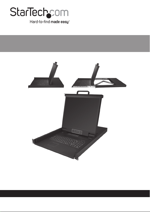
16-Port VGA Rackmount LCD Console
| 19 in. | 1U
User Manual
SKU#: RKCONS1916K
Actual product may vary from photos
For the latest information and specications visit
www.startech.com/RKCONS1916K
Manual Revision: 01/18/2019
Page 2

Compliance Statements
FCC Compliance Statement
This equipment has been tested and found to comply with the limits for a Class
B digital device, pursuant to part 15 of the FCC Rules. These limits are designed
to provide reasonable protection against harmful interference in a residential
installation. This equipment generates, uses and can radiate radio frequency
energy and, if not installed and used in accordance with the instructions, may
cause harmful interference to radio communications. However, there is no
guarantee that interference will not occur in a particular installation. If this
equipment does cause harmful interference to radio or television reception,
which can be determined by turning the equipment o and on, the user is
encouraged to try to correct the interference by one or more of the following
measures:
• Reorient or relocate the receiving antenna
• Increase the separation between the equipment and receiver
• Connect the equipment into an outlet on a circuit dierent from that to
which the receiver is connected
• Consult the dealer or an experienced radio/TV technician for help
Industry Canada Statement
This Class B digital apparatus complies with Canadian ICES-003.
Cet appareil numérique de la classe [B] est conforme à la norme NMB-003 du
Canada.
CAN ICES-3 (B)/NMB-3(B)
This device complies with Industry Canada licence-exempt RSS standard(s).
Operation is subject to the following two conditions:
(1) This device may not cause interference, and (2) This device must accept any
interference, including interference that may cause undesired operation of the
device.
Le présent appareil est conforme aux CNR d’Industrie Canada applicables
aux appareils radio exempts de licence. L’exploitation est autorisée aux deux
conditions suivantes:
(1) l’appareil ne doit pas produire de brouillage, et (2) l’utilisateur de l’appareil
doit accepter tout brouillage radioélectrique subi, même si le brouillage est
susceptible d’en compromettre le fonctionnement.
To view manuals, videos, drivers, downloads, technical drawings, and more visit www.startech.com/support
1
Page 3

Use of Trademarks, Registered Trademarks, and other
Protected Names and Symbols
This manual may make reference to trademarks, registered trademarks, and
other protected names and/or symbols of third-party companies not related in
any way to StarTech.com. Where they occur these references are for illustrative
purposes only and do not represent an endorsement of a product or service
by StarTech.com, or an endorsement of the product(s) to which this manual
applies by the third-party company in question. Regardless of any direct
acknowledgement elsewhere in the body of this document, StarTech.com
hereby acknowledges that all trademarks, registered trademarks, service marks,
and other protected names and/or symbols contained in this manual and
related documents are the property of their respective holders.
To view manuals, videos, drivers, downloads, technical drawings, and more visit www.startech.com/support
2
Page 4

Safety Statements
Safety Measures
• Wiring terminations should not be made with the product and/or electric
lines under power.
• Product installation and/or mounting should be completed by a certied
professional as per the local safety and building code guidelines.
• Cables (including power and charging cables) should be placed and routed
to avoid creating electric, tripping or safety hazards.
Mesures de sécurité
• Les terminaisons de câblâge ne doivent pas être eectuées lorsque le produit
et/ou les câbles électriques sont sous tension.
• L’installation et/ou le montage du produit doit être réalisé par un
professionnel certié et dans le respect des normes locales et du code de
construction local.
• Les câbles (y compris les câbles d’alimentation et de chargement) doivent
être placés et acheminés de façon à éviter tout risque électrique, de chute ou
de sécurité
安全対策
• 電源が入っている状態の製品または電線の終端処理を行わないでくださ
い。
• 製品の設置やマウントは、使用地域の安全ガイドラインおよび建築基準に
従い、有資格の専門業者が行うようにしてください。
• ケーブル(電源ケーブルと充電ケーブルを含む)は、適切な配置と引き回し
を行い、電気障害やつまづきの危険性など、安全上のリスクを回避するよう
にしてください 。
Misure di sicurezza
• I terminiali dei li elettrici non devono essere realizzate con il prodotto e/o le
linee elettriche sotto tensione.
• L’installazione e/o il montaggio dei prodotti devono essere eseguiti da un
tecnico professionale certicato che conosca le linee guida locali sulle norme
edilizie e sulla sicurezza.
• I cavi (inclusi i cavi di alimentazione e di ricarica) devono essere posizionati
e stesi in modo da evitare pericoli di inciampo, rischi di scosse elettriche o
pericoli per la sicurezza.
To view manuals, videos, drivers, downloads, technical drawings, and more visit www.startech.com/support
3
Page 5

Säkerhetsåtgärder
• Montering av kabelavslutningar får inte göras när produkten och/eller
elledningarna är strömförda.
• Installation och/eller montering får endast göras av behöriga yrkespersoner
och enligt gällande lokala förordningar för säkerhet och byggnormer.
• Kablar (inklusive elkablar och laddningskablar) ska dras och placeras på så
sätt att risk för snubblingsolyckor och andra olyckor kan undvikas.
Warning Statements
• Make sure to assemble this product according to the instructions. Failure to
do so might result in personal injury or property damage.
• Never use this product if parts are missing or damaged.
To view manuals, videos, drivers, downloads, technical drawings, and more visit www.startech.com/support
4
Page 6

Table of Contents
Compliance Statements ........................................................................1
Safety Statements ..................................................................................3
Warning Statements ..............................................................................4
Product Diagram (RKCONS1908K) ......................................................8
Front ............................................................................................................................................................... 8
Rear ................................................................................................................................................................ 9
Product Information ..............................................................................10
Packaging Contents ................................................................................................................................. 10
Hardware Kit Contents ............................................................................................................................ 10
Requirements ............................................................................................................................................. 10
Installation ..............................................................................................11
Mounting the Rack Console Drawer .................................................................................................. 11
Grounding the LCD Console .................................................................................................................12
Connecting the LCD Console ................................................................................................................12
Opening the LCD Console ......................................................................................................................13
Closing the LCD Console ........................................................................................................................13
Panel Controls and On-Screen Display (OSD) Functions .................14
Console Panel Menu ................................................................................................................................ 14
OSD ..........................................................................................................15
Accessing the OSD .................................................................................................................................... 15
Operations/Menu Titles .......................................................................................................................... 15
Navigation ................................................................................................................................................... 16
To view manuals, videos, drivers, downloads, technical drawings, and more visit www.startech.com/support
5
Page 7

Administrator (ADM) Menu ..................................................................17
Accessing the Administrator Menu ....................................................................................................17
Setting up a User Account ..................................................................................................................... 18
Setting up User Access ............................................................................................................................ 20
Turning On/O Broadcast (BRC) Mode ............................................................................................. 21
Scanning All Ports ..................................................................................................................................... 22
Scanning All Ports That Are Powered On.......................................................................................... 23
Scanning All Quick View Ports ..............................................................................................................24
Performing an Auto Scan ....................................................................................................................... 24
Conguring the Port ID ........................................................................................................................... 25
Setting a Default HotKey ........................................................................................................................ 27
Setting Logout Time O .........................................................................................................................29
Resetting the Keyboard and Mouse ................................................................................................... 30
Turning the Beeper On/O .................................................................................................................... 31
Turning the Mouse On/O .................................................................................................................... 32
Restoring Factory Settings ..................................................................................................................... 33
Viewing Console Information ............................................................................................................... 34
Editing Port Names ................................................................................................................................... 35
Setting Quick View Ports ........................................................................................................................36
Logging Out of the OSD ......................................................................................................................... 37
Hotkeys ....................................................................................................37
LED Indicator ..........................................................................................38
Conguration ..........................................................................................38
Testing the LCD Console ......................................................................................................................... 38
Conguring Display Settings ................................................................................................................ 39
To view manuals, videos, drivers, downloads, technical drawings, and more visit www.startech.com/support
6
Page 8

Specications ..........................................................................................39
Important Considerations ....................................................................41
To view manuals, videos, drivers, downloads, technical drawings, and more visit www.startech.com/support
7
Page 9
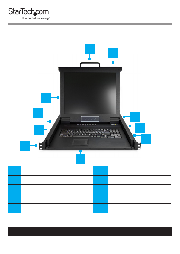
Product Diagram (RKCONS1916K)
Front
5
4
6
3
2
7
8
9
1
10
1 Mounting Bracket x 2 6 Release Switch
2 Current Port 7 Display Menu Buttons
3 Port Select Buttons/LEDs 8 Keyboard LEDs
4 Display 9 Rails x 2
5 Handle 10 Touch pad
To view manuals, videos, drivers, downloads, technical drawings, and more visit www.startech.com/support
8
Page 10
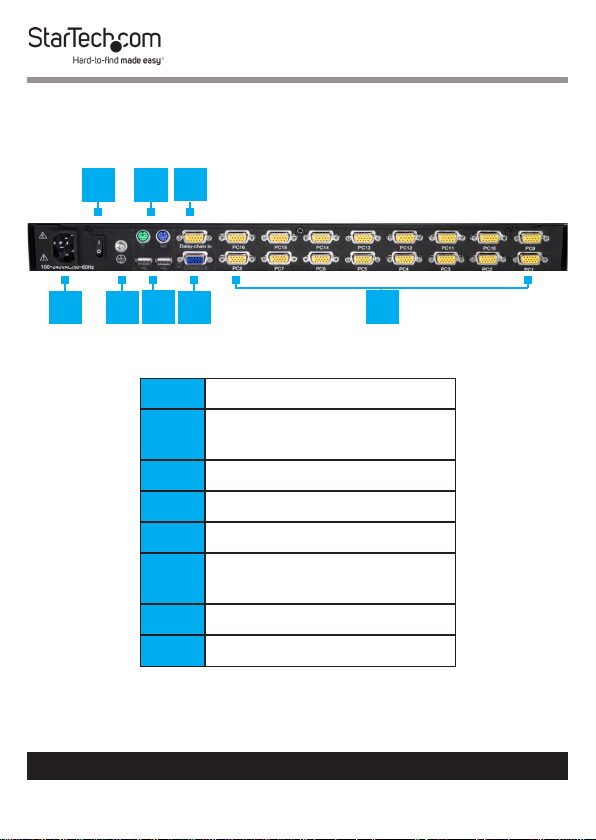
Rear
3
2
1
6
4 5
To view manuals, videos, drivers, downloads, technical drawings, and more visit www.startech.com/support
7
1 Power Switch
2 PS2 Mouse and Keyboard
Ports
3 Daisy Chain Port
4 Power Connection Port
5 Ground Connection Screw
6 USB Mouse and Keyboard
Ports
7 Console Monitor Port
8 Host Port x 8
9
8
Page 11

Product Information
Packaging Contents
• 1U LCD Rack Console Drawer x 1
• Host Cable Kit x 16
• Mounting Rails - Set x 2
• Power Cords (NA, JP, UK, EU, ANZ) x 5
• M5 Cage Nuts x 8
• M5 Screws x 8
• Quick-Start Guide x 1
• Side Rails with Brackets x 2
• Keys x 2
• Screw Kit x 1
Requirements
Requirements are subject to change. For the latest
requirements, please visit www.startech.com/RKCONS1916K.
• 1U of Rack Space
• Grounding Wire
• Power Source
• Computer, Server, or KVM
• Phillips Head Screwdriver
To view manuals, videos, drivers, downloads, technical drawings, and more visit www.startech.com/support
10
Page 12

Installation
Mounting the Rack Console Drawer
Note: It’s easier to install the Rack Console Drawer if an-
other person helps you with the installation.
Warning: Use caution and proper lifting techniques when
installing the Rack Console Drawer.
1. Based on the mounting depth of the server rack that you are
using, select the appropriate length of Mounting Rails.
2. Decide where in the Rack you want to install the Rack
Console Drawer.
3. Insert the M5 Cage Nuts (two per mounting post) into the
square mounting holes on the Rack’s mounting posts.
4. Align the Rear Mounting Brackets (rails) with the M5 Cage
Nuts on the corresponding Rack mounting post.
5. Insert an M5 Screw (two per mounting post) through the
Rear Mounting Bracket (rail) and into the M5 Cage Nut. Do
not tighten the M5 Screws.
6. With assistance, slide the Rack Console Drawer into the
Rack, guiding the Rear Mounting Brackets (rails) into the
rail assembly.
7. Insert an M5 Screw (two per mounting post) through the
Front Mounting Bracket (rail) into the M5 Cage Nut.
8. Use a Phillips Head Screwdriver to tighten the M5 Screws.
To view manuals, videos, drivers, downloads, technical drawings, and more visit www.startech.com/support
11
Page 13

Grounding the LCD Console
Note: Grounding is recommended in environments with
high levels of electromagnetic interference (EMI), or frequent
electrical surges.
1. Using a Phillips Head Screwdriver, loosen the Grounding
Connection Screw.
2. Attach the Grounding Wire to the shaft of the Grounding
Connection Screw.
3. Tighten the Grounding Connection Screw, making sure not
to over-tighten.
4. Attach the other end of the Grounding Wire (not connected
to the LCD Console) to a proper earth-ground connection.
Connecting the LCD Console
To connect the LCD Console to a Computer or KVM, perform
the following steps:
1. Turn o the Computer or KVM Switch.
2. Connect the 15-pin Host/KVM Connector on the KVM
Cable to the Host Port on the LCD Console and to a VGA
port and USB port on the rear panel of the Computer or
KVM Switch.
3. Connect the Power Cable to the Power Connection Port on
the LCD Console and to an AC Electrical Outlet.
4. Power on the LCD Console.
5. Power the Computer or KVM back on.
To view manuals, videos, drivers, downloads, technical drawings, and more visit www.startech.com/support
12
Page 14
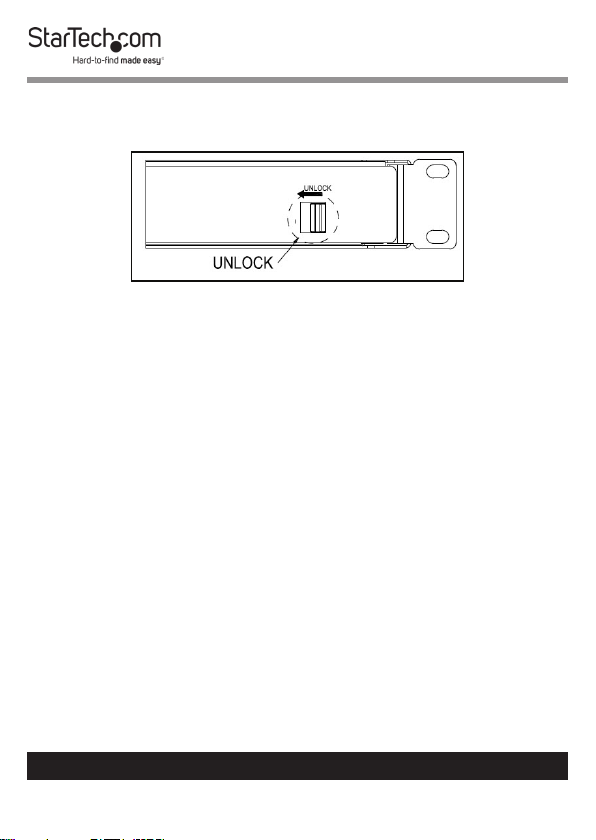
Opening the LCD Console
1. Move the Release Switch to the unlocked position.
Unlocking the LCD Console
2. Use the Handle to pull the LCD Console out of the Rack
until you hear the LCD Console click into place. The LCD
Console will power On.
3. The LED Indicator on the left of the monitor panel changes
from orange to green.
4. Adjust the Display into the desired position.
Closing the LCD Console
1. Lower the Display until it’s ush against the Keyboard.
2. Slide and hold the two Switches located on the sides of the
LCD Console forward and push the LCD Console in towards
the rear of the rack.
3. Release the two Switches and continue pushing the LCD
Console the rest of the way into the Rack, until you hear an
audible click.
To view manuals, videos, drivers, downloads, technical drawings, and more visit www.startech.com/support
13
Page 15

Panel Controls and On-Screen Display (OSD) Functions
Console Panel Menu
The Console Panel buttons are for display adjustments and
OSD navigation:
Button Function
Auto-synchronizes and scales down the
Auto/Exit
SL-
SL+
Menu/
Select
Port
Selection
Buttons
display to any valid factory preset timings.
Exits the OSD.
Press to scroll to the function you want to
adjust.
Press to scroll to the function you want to
adjust.
Open the LCD OSD menu.
Used to select an option on the OSD.
Used to quick select/change ports.
To view manuals, videos, drivers, downloads, technical drawings, and more visit www.startech.com/support
14
Page 16

OSD
Accessing the OSD
There are two ways to access the On Screen Display (OSD):
• Using a Mouse double click the Right Mouse button.
• Using a Keyboard press the Scroll Lock button twice.
Operations/Menu Titles
The following Titles will appear on the operations menus within
the OSD:
Titles Description
SN The level number or port number.
$ The corresponding computers are
powered on and are online.
QV • #: Allows you to quick view the
selected port.
• BC: Indicates that the port is board
casting.
LK • @: Indicates that the port is only
available to view.
Name The name of the port.
To view manuals, videos, drivers, downloads, technical drawings, and more visit www.startech.com/support
15
Page 17

Navigation
Button Description
Left and Right Arrows Used to move left and right
on the screen accessing
menu options.
Up and Down Arrows Used to move up and down
on the screen accessing
menu options.
Enter Select the highlighted
option.
Esc Cancels operation and exits
the current menu.
To view manuals, videos, drivers, downloads, technical drawings, and more visit www.startech.com/support
16
Page 18

Administrator (ADM) Menu
Accessing the Administrator Menu
• On the OSD screen, press the F1 button, the ADM drop-
down menu will appear.
Administrator screen
To view manuals, videos, drivers, downloads, technical drawings, and more visit www.startech.com/support
17
Page 19

Setting up a User Account
The Set User Login option, allows you to setup user accounts.
1. On the OSD screen, press the F1 button.
2. Select Set User Login from the Administrator drop-down
menu and press Enter.
User screen
3. Select the Administrator to setup an administrator user or
User to setup a normal user.
To view manuals, videos, drivers, downloads, technical drawings, and more visit www.startech.com/support
18
Page 20

4. Press the Enter button. The User Name and Password
screen will appear.
User Name and Password screen
5. Enter a user name (max. 16 characters) in either the ADMINI
eld or the USER eld, depending on the type of user you
are creating.
6. Enter a password (max. 16 characters) in the Password eld
and re-enter the same password in the Conrm eld.
7. Press the Enter button.
8. A pop-up screen will appear indicating either “User setup
OK” or “Password not match”. If you see “Password not match”
you need to re-enter the password in both the Password
and Conrm elds and press Enter.
To view manuals, videos, drivers, downloads, technical drawings, and more visit www.startech.com/support
19
Page 21

Setting up User Access
The Set Accessible option, allows you to setup a user’s system
access either Full, View, or Null.
1. On the OSD screen, press the F1 button.
2. Select Set Accessible from the Administrator drop-down
menu and press Enter.
Permissions screen
3. The Permissions screen enables you to set a user’s access to
a corresponding port, either:
• Full: Gives the user full access to perform all operations on
the port.
• View: Gives the user view only access.
To view manuals, videos, drivers, downloads, technical drawings, and more visit www.startech.com/support
20
Page 22

• Null: The user does not have access to the corresponding
port and the port name will not appear on the users list of
ports.
Note: The Administrator has full access to all ports.
4. Use the Left and Right arrow buttons to navigate to the port
and user you want to set permissions for.
5. Use the Space Bar to toggle through the dierent
permissions, F = Full, V = View, and N = Null.
6. Once you have setup the users permissions, press the Enter
button to complete the setup.
Turning On/O Broadcast (BRC) Mode
1. On the OSD screen, press the F1 button.
2. Select BRC Mode from the Administrator drop-down menu
and press Enter and On icon will appear next to BRC Mode.
BRC Mode
To view manuals, videos, drivers, downloads, technical drawings, and more visit www.startech.com/support
21
Page 23

3. The OSD screen will appear listing all available ports.
4. Using the Left and Right arrow buttons select a port you
want to enable broadcasting on.
5. Press the F7 button to enable or disable BRC Mode.
Note: When BRC Mode is active a icon will appear next
to the port.
Scanning All Ports
1. On the OSD screen, press the F2 button.
2. Select All from the Scan drop-down menu and press Enter
to scan all the port.
Scan menu
To view manuals, videos, drivers, downloads, technical drawings, and more visit www.startech.com/support
22
Page 24

Scanning All Ports That Are Powered On
1. On the OSD screen, press the F2 button.
2. Select Power On from the Scan drop-down menu and press
Enter to scan all the port.
Scan menu
To view manuals, videos, drivers, downloads, technical drawings, and more visit www.startech.com/support
23
Page 25

Scanning All Quick View Ports
1. On the OSD screen, press the F2 button.
2. Select Quick View from the Scan drop-down menu and
press Enter to scan all the port.
Scan menu
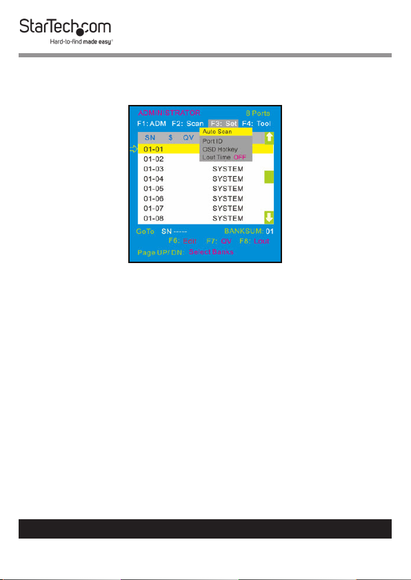
Performing an Auto Scan
1. On the OSD screen, press the F3 button.
To view manuals, videos, drivers, downloads, technical drawings, and more visit www.startech.com/support
24
Page 26

2. Select Auto Scan from the Set drop-down menu and press
Enter to perform an auto scan.
Set Menu
Conguring the Port ID
1. On the OSD screen, press the F3 button.
To view manuals, videos, drivers, downloads, technical drawings, and more visit www.startech.com/support
25
Page 27
2. Select Port ID from the Scan drop-down menu and press
Enter.
Set Menu
3. Select one of the following port ID options:
• 0S: The port ID is not displayed.
• 1-98s: The port ID is displayed for the specied amount of
time in seconds, from 1 - 98 seconds.
• 99s: The port ID is always displayed.
To view manuals, videos, drivers, downloads, technical drawings, and more visit www.startech.com/support
26
Page 28

Setting a Default HotKey
1. On the OSD screen, press the F3 button.
2. Select OSD Hotkey from the Set drop-down menu and
press Enter.
Set Menu
To view manuals, videos, drivers, downloads, technical drawings, and more visit www.startech.com/support
27
Page 29

3. On the OSD HOTKEY screen, select which Hotkey setting you
want to set as the default Hotkey, Scr Lock, CAPS, F12, or Crtl.
Note: When the Ctrl + Ctrl + KVM Hotkey option is select-
ed as the default hotkey, double clicking the Right Mouse
button will no longer bring up the OSD.
OSD HOTKEY screen
4. Press the Enter button while highlighting a Hotkey to set it
as the new default Hotkey.
To view manuals, videos, drivers, downloads, technical drawings, and more visit www.startech.com/support
28
Page 30

Setting Logout Time O
1. On the OSD screen, press the F3 button.
2. Select Lout Time from the Set drop-down menu and press
Enter to scan all the port.
Set Menu
3. Select one of the following logout time options:
• 0: Deactivates the screen saver.
• 01-99m: The screen saver is displayed for the specied
amount of time in minutes, from 01 - 99 minutes.
To view manuals, videos, drivers, downloads, technical drawings, and more visit www.startech.com/support
29
Page 31

Resetting the Keyboard and Mouse
1. On the OSD screen, press the F4 button.
2. Select Reset KM from the Tool drop-down menu and press
Enter to rest the connected Keyboard and Mouse.
Tool Menu
To view manuals, videos, drivers, downloads, technical drawings, and more visit www.startech.com/support
30
Page 32

Turning the Beeper On/O
1. On the OSD screen, press the F4 button.
2. Select Beeper from the Tool drop-down menu and press
Enter to turn the Beeper on/o.
Tool Menu
To view manuals, videos, drivers, downloads, technical drawings, and more visit www.startech.com/support
31
Page 33

Turning the Mouse On/O
1. On the OSD screen, press the F3 button.
2. Select Mouse Hot from the Tool drop-down menu and press
Enter to turn the Mouse on/o.
Tool Menu
To view manuals, videos, drivers, downloads, technical drawings, and more visit www.startech.com/support
32
Page 34

Restoring Factory Settings
1. On the OSD screen, press the F3 button.
2. Select Restore Values from the Tool drop-down menu and
press Enter to reset the setting on the Console to factory
defaults.
Tool Menu
To view manuals, videos, drivers, downloads, technical drawings, and more visit www.startech.com/support
33
Page 35

Viewing Console Information
1. On the OSD screen, press the F3 button.
2. Select About KVM from the Tool drop-down menu and
press Enter to view the Console’s version information.
Tool Menu
To view manuals, videos, drivers, downloads, technical drawings, and more visit www.startech.com/support
34
Page 36

Editing Port Names
1. On the OSD screen, select the port you want to change.
Highlight the Port
2. Press the F6 button.
3. Enter the port’s new name.
4. Press the Enter button to save the new name.
- or -
5. Press the Esc button to cancel and exit.
To view manuals, videos, drivers, downloads, technical drawings, and more visit www.startech.com/support
35
Page 37

Setting Quick View Ports
1. On the OSD screen, select the port you want to change.
Setting a Quick View Port
2. Press the F7 button.
3. A icon will appear in the QV eld, indicating the port is
now set as a quick view port.
4. Press the F7 button on the port a second time to deactivate
the quick view status.
To view manuals, videos, drivers, downloads, technical drawings, and more visit www.startech.com/support
36
Page 38

Logging Out of the OSD
• On the OSD screen, press the F8 button to exit the OSD and
return to the Login screen.
Login screen
Hotkeys
Keys Description
Scr Lck + 1 - 8 Port selection 1 - 8
Scr Lck + F1 - F8 Skip ports from 9 - 16
Scr Lck + S Preform Auto Scan
Scr Lck + Space Bar Brings up the OSD screen
To view manuals, videos, drivers, downloads, technical drawings, and more visit www.startech.com/support
37
Page 39

LED Indicator
LED Indicator Status
Power LED Green: On
Red: Standby, Suspend,
or O
Port Selection LEDs Green: Indicates
that the console
is connected to a
Computer.
Orange: Indicates that
the Computer attached
to the corresponding
port is properly
connected.
Conguration
Testing the LCD Console
To test that the LCD Console is working properly, perform the
following steps:
1. Power up the Rack Console, and then turn on the
Computer.
To view manuals, videos, drivers, downloads, technical drawings, and more visit www.startech.com/support
38
Page 40

2. Make sure that the video image is centered on the screen.
If the image is not centered, use the LCD OSD controls to
adjust the image (see Panel Controls and OSD Functions)
or press the Auto button on the LCD Control Panel.
Note: If the unit does not power up when the Display is
pulled up, try toggling the Power switch on the rear of the
LCD Console.
Conguring Display Settings
When the LCD Console is rst connected you may need to
congure one or more display settings. Use the Computer’s
operating system to congure the following display settings:
• Display mode: also called desktop area or video resolution
• Refresh rate: also called vertical scan rate or vertical sync
• Color depth: also called color palette or number of colors
Specications
Specication Description
Panel Type Active Matrix TFT LCD
Max. Resolution 1280 x 1024
Supported Colors 16M Colors (6-bit with
FRC)
Response Time Rising Time: 8ms
Decay Time: 8ms
To view manuals, videos, drivers, downloads, technical drawings, and more visit www.startech.com/support
39
Page 41

System Cables VGA + USB
Keyboard 99-key
Mouse Touchpad
Sync 50 - 75KHz
Power Source 100 - 240 VAC Input
Operating Temperature Celsius: 0 ° - 50 °
Fahrenheit: 32 ° - 122 °
Storage Temperature Celsius: -20 ° - 60 °
Fahrenheit: -4 ° - 140 °
Humidity 10% - 90% RH
Dimensions 447.5 x 482 x 44 mm
To view manuals, videos, drivers, downloads, technical drawings, and more visit www.startech.com/support
40
Page 42

Important Considerations
• If you’re installing the device in a closed or multi-unit
rack assembly, ensure that the environmental conditions
are within the LCD Console’s maximum and minimum
specications.
• Installing the LCD Console in a rack or cabinet may reduce
airow. Consider your airow requirement when selecting a
location for installation.
• It’s recommended that the LCD Console be connected to a
power source with over-current protection and supply wiring.
Appropriate consideration of equipment nameplate ratings
should be used when addressing this concern.
• The LCD Console should be grounded appropriately during
installation.
To view manuals, videos, drivers, downloads, technical drawings, and more visit www.startech.com/support
41
Page 43

Warranty Information
This product is backed by a two-year warranty.
For further information on product warranty terms and conditions, please refer
to www.startech.com/warranty.
Limitation of Liability
In no event shall the liability of StarTech.com Ltd. and StarTech.com USA LLP (or
their ocers, directors, employees or agents) for any damages (whether direct
or indirect, special, punitive, incidental, consequential, or otherwise), loss of
prots, loss of business, or any pecuniary loss, arising out of or related to the use
of the product exceed the actual price paid for the product.
Some states do not allow the exclusion or limitation of incidental or
consequential damages. If such laws apply, the limitations or exclusions
contained in this statement may not apply to you.
To view manuals, videos, drivers, downloads, technical drawings, and more visit www.startech.com/support
42
42
Page 44

Hard-to-nd made easy. At StarTech.com, that isn’t a slogan.
It’s a promise.
StarTech.com is your one-stop source for every connectivity part you need.
From the latest technology to legacy products — and all the parts that bridge
the old and new — we can help you nd the parts that connect your solutions.
We make it easy to locate the parts, and we quickly deliver them wherever they
need to go. Just talk to one of our tech advisors or visit our website. You’ll be
connected to the products you need in no time.
Visit www.startech.com for complete information on all StarTech.com products
and to access exclusive resources and time-saving tools.
StarTech.com is an ISO 9001 Registered manufacturer of connectivity and
technology parts. StarTech.com was founded in 1985 and has operations in the
United States, Canada, the United Kingdom and Taiwan servicing a worldwide
market.
Reviews
Share your experiences using StarTech.com products, including product
applications and setup, what you love about the products, and areas for
improvement.
StarTech.com Ltd.
45 Artisans Cres.
London, Ontario
N5V 5E9
Canada
StarTech.com LLP
2500 Creekside Pkwy.
Lockbourne, Ohio
43137
U.S.A.
StarTech.com Ltd.
Unit B, Pinnacle
15 Gowerton Rd.,
Brackmills
Northampton
NN4 7BW
United Kingdom
FR: fr.startech.com
DE: de.startech.com
To view manuals, videos, drivers, downloads, technical drawings, and more visit www.startech.com/support
ES: es.startech.com
NL: nl.startech.com
IT: it.startech.com
JP: jp.startech.com
 Loading...