

Page 1
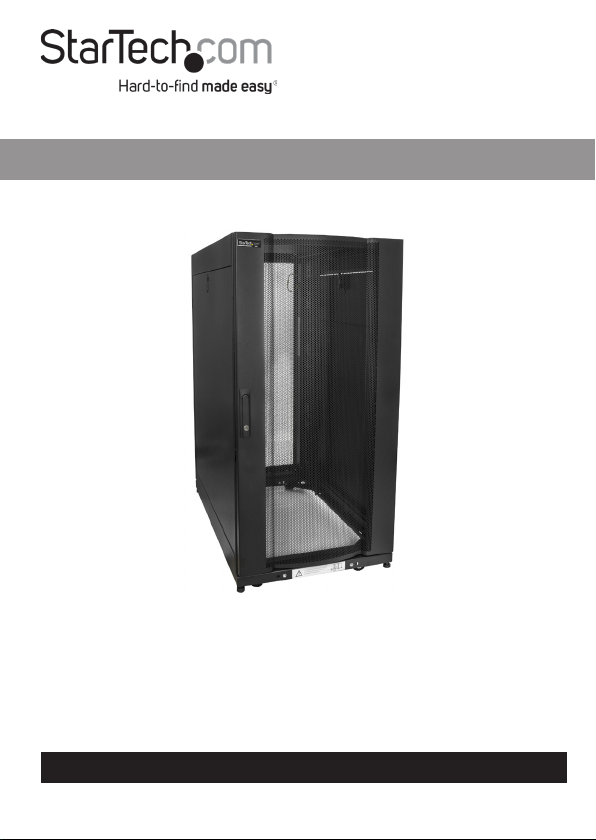
25U Rack Enclosure
User Manual
SKU#: RK2537BKM
Actual product may vary from photos
For the latest information and specications visit
www.startech.com/RK2537BKM
Manual Revision: 09/18/2018
Page 2

Compliance Statements
FCC Compliance Statement
This equipment has been tested and found to comply
with the limits for a Class B digital device, pursuant to part
15 of the FCC Rules. These limits are designed to provide
reasonable protection against harmful interference in a
residential installation. This equipment generates, uses and
can radiate radio frequency energy and, if not installed and
used in accordance with the instructions, may cause harmful
interference to radio communications. However, there is
no guarantee that interference will not occur in a particular
installation. If this equipment does cause harmful interference
to radio or television reception, which can be determined by
turning the equipment o and on, the user is encouraged to
try to correct the interference by one or more of the following
measures:
• Reorient or relocate the receiving antenna
• Increase the separation between the equipment and receiver
• Connect the equipment into an outlet on a circuit dierent
from that to which the receiver is connected
• Consult the dealer or an experienced radio/TV technician for
help
For the State of California
WARNING: Cancer and Reproductive Harm
www.P65Warnings.ca.gov
To view manuals, videos, drivers, downloads, technical drawings, and more visit www.startech.com/support
1
Page 3

Use of Trademarks, Registered Trademarks, and other
Protected Names and Symbols
This manual may make reference to trademarks, registered
trademarks, and other protected names and/or symbols of
third-party companies not related in any way to StarTech.com.
Where they occur these references are for illustrative purposes
only and do not represent an endorsement of a product or
service by StarTech.com, or an endorsement of the product(s)
to which this manual applies by the third-party company
in question. Regardless of any direct acknowledgement
elsewhere in the body of this document, StarTech.com hereby
acknowledges that all trademarks, registered trademarks,
service marks, and other protected names and/or symbols
contained in this manual and related documents are the
property of their respective holders.
To view manuals, videos, drivers, downloads, technical drawings, and more visit www.startech.com/support
2
Page 4

Safety Statements
Safety Measures
• Wiring terminations should not be made with the product and/or electric
lines under power.
• Product installation and/or mounting should be completed by a certied
professional as per the local safety and building code guidelines.
• Cables (including power and charging cables) should be placed and routed
to avoid creating electric, tripping or safety hazards.
Mesures de sécurité
• Les terminaisons de câblâge ne doivent pas être eectuées lorsque le produit
et/ou les câbles électriques sont sous tension.
• L’installation et/ou le montage du produit doit être réalisé par un
professionnel certié et dans le respect des normes locales et du code de
construction local.
• Les câbles (y compris les câbles d’alimentation et de chargement) doivent
être placés et acheminés de façon à éviter tout risque électrique, de chute ou
de sécurité
安全対策
• 電源が入っている状態の製品または電線の終端処理を行わないでください。
• 製品の設置やマウントは、使用地域の安全ガイドラインおよび建築基準に従い、有資格の専門業者が行うようにしてください。
• ケーブル(電源ケーブルと充電ケーブルを含む)は、適切な配置と引き回しを行い、電気障害やつまづきの危険性など、安全上のリスクを回避するよう
にしてください。
Misure di sicurezza
• I terminiali dei li elettrici non devono essere realizzate con il prodotto e/o le
linee elettriche sotto tensione.
• L’installazione e/o il montaggio dei prodotti devono essere eseguiti da un
tecnico professionale certicato che conosca le linee guida locali sulle norme
edilizie e sulla sicurezza.
• I cavi (inclusi i cavi di alimentazione e di ricarica) devono essere posizionati
e stesi in modo da evitare pericoli di inciampo, rischi di scosse elettriche o
pericoli per la sicurezza.
To view manuals, videos, drivers, downloads, technical drawings, and more visit www.startech.com/support
3
Page 5

Säkerhetsåtgärder
• Montering av kabelavslutningar får inte göras när produkten och/eller
elledningarna är strömförda.
• Installation och/eller montering får endast göras av behöriga yrkespersoner
och enligt gällande lokala förordningar för säkerhet och byggnormer.
• Kablar (inklusive elkablar och laddningskablar) ska dras och placeras på så
sätt att risk för snubblingsolyckor och andra olyckor kan undvikas.
Warning Statements
• Make sure that you assemble this product according to the instructions.
• Do not exceed the weight capacity of this product. Overloading this product
might result in injury or property damage. This product can support the
following weight: 2320.5lbs (rolling) and 3315lbs (stationary)
• This product is intended for indoor use only and should not be used
outdoors.
• This enclosure is extremely heavy. Never attempt to move or lift this
enclosure without assistance.
• Tipping hazard! Extending multiple components from this enclosure
increases the chance that the enclosure will tip over. To avoid this risk, do not
extend more than one component from the enclosure.
• Do not place any items on this enclosure and do not stack the enclosure on
top of another enclosure.
• Keep liquid away from this enclosure.
• Make sure that you install the enclosure in an area that can handle the
combined weight of the enclosure and the equipment that you intend to
place inside of the enclosure.
• This product requires an earth ground connection. Do not use this product
without an earth ground connection.
Varningsmeddelanden
• Se till att du monterar produkten i enlighet med instruktionerna.
• Överskrid inte produktens viktkapacitet. Överbelastning av produkten kan
orsaka skada på person eller egendom. Denna produkt har stöd för följande
vikter: 363 kg.
• Produkten är endast avsedd för användning inomhus och ska inte användas
utomhus.
• Detta skåp är extremt tungt. Försök aldrig ytta på skåpet eller lyfta det utan
hjälp.
• Risk för vältning! Att förlänga era komponenter från detta skåp ökar risken
för att det välter. Förläng inte er än en komponent från skåpet för att
To view manuals, videos, drivers, downloads, technical drawings, and more visit www.startech.com/support
4
Page 6

undvika risk.
• Placera inte saker ovanpå skåpet och ställ inte skåpet ovanpå ett annat skåp.
• Håll vätskor borta från skåpet.
• Se till att du installerar skåpet på en plats som kan hantera den kombinerade
vikten av skåpet och utrustningen som du tänker placera inuti.
• Produkten behöver en jordad anslutning. Använd inte produkten utan en
jordad anslutning.
Avertissements
• Assemblez ce produit conformément aux instructions.
• Ne dépassez pas la capacité pondérale du produit. Une surcharge du produit
peut entraîner des blessures ou des dommages matériels. Ce produit peut
supporter 363 kg.
• Ce produit est uniquement destiné à une utilisation en intérieur et ne doit
pas être utilisé à l’extérieur.
• Ce rack de serveur est extrêmement lourd. Ne tentez jamais de le déplacer ou
de le soulever sans aide.
• Risque de basculement! L’extension de plusieurs composants à partir du
rack de serveur augmente le risque de basculement. Pour éviter ce risque,
n’étendez pas plus d’un composant à partir du rack de serveur.
• Ne placez aucun objet sur ce rack de serveur et n’empilez pas le rack sur un
autre rack.
• N’approchez aucun liquide du rack de serveur.
• Veillez à installer le rack de serveur dans un endroit pouvant supporter le
poids combiné du rack et des équipements que vous comptez placer à
l’intérieur.
• Ce produit nécessite un raccordement à la terre. N’utilisez pas ce produit sans
raccordement à la terre.
Warnhinweise
• Beachten Sie bei der Montage dieses Produkts die Montageanweisungen.
• Überschreiten Sie nicht die Tragkraft dieses Produkts. Ein Überladen dieses
Produkts kann zu Verletzungen oder zur Beschädigung des Produkts führen.
Dieses Produkt ist für folgendes Gewicht geeignet: 363 kg.
• Dieses Produkt ist nur zum Gebrauch in Innenräumen vorgesehen und sollte
nicht im Freien verwendet werden.
• Dieses Gehäuse ist extrem schwer. Versuchen Sie niemals, dieses Gehäuse
ohne Hilfe zu bewegen oder anzuheben.
• Kippgefahr! Das Ausziehen mehrerer Komponenten aus diesem Gehäuse
erhöht die Chance, dass das Gehäuse umkippt. Um dies zu vermeiden, ziehen
Sie niemals mehr als eine Komponente aus diesem Gehäuse aus.
To view manuals, videos, drivers, downloads, technical drawings, and more visit www.startech.com/support
5
Page 7

• Platzieren Sie keine Gegenstände auf dem Gehäuse und stapeln Sie das
Gehäuse nicht auf einem anderen Gehäuse.
• Halten Sie Flüssigkeiten von diesem Gehäuse fern.
• Vergewissern Sie sich, dass der Untergrund, auf dem das Gehäuse aufgestellt
wird, in der Lage ist, das Gesamtgewicht des Gehäuses und der Geräte, die
Sie darin platzieren möchten, zu tragen.
• Dieses Produkt erfordert einen Schutzleiteranschluss. Verwenden Sie das
Produkt nicht ohne einen Schutzleiteranschluss.
Dichiarazioni di avvertenza
• Assicurarsi di Assemblare il prodotto secondo le istruzioni.
• Non superare la capacità di carico del prodotto. Il sovraccarico del prodotto
potrebbe causare danni o lesioni. Il prodotto è in grado di supportare i
seguenti pesi: 363 kg.
• Il prodotto è destinato all’uso in ambienti interni. Se ne sconsiglia l’impiego
in ambienti esterni.
• Il box esterno è molto pesante. Non tentare di spostarlo o sollevarlo senza
assistenza.
• Pericolo di ribaltamento! L’estensione di più componenti dal box esterno
aumenta il rischio di ribaltamento del box esterno. Per evitare questo rischio,
non estendere più di un componente dal box esterno.
• Non collocare oggetti sul box esterno e non impilare un box esterno sopra
un altro.
• Tenere il box esterno lontano dai liquidi.
• Assicurarsi di installarlo in un punto che possa sorreggere il peso combinato
del box esterno e dell’apparecchiatura che si intende collocare al suo interno.
• Il prodotto richiede una messa a terra. Non utilizzare il prodotto in assenza di
una messa a terra.
Mensagens de aviso
• Certique-se de que monta este produto de acordo com as instruções.
• Não exceda a capacidade de peso deste produto. Sobrecarregar este produto
pode resultar em ferimentos ou danos de propriedade. Este produto pode
suportar o seguinte peso: 363 kg.
• Este produto destina-se apenas a uma utilização no interior e não deve ser
utilizado no exterior.
• Esta caixa é extremamente resistente. Nunca tente mover ou levantar esta
caixa sem assistência.
• Perigo de queda! Estender vários componentes desta caixa aumenta a
probabilidade desta caixa cair. Para evitar este risco, não expandir mais de
um componente desta caixa.
To view manuals, videos, drivers, downloads, technical drawings, and more visit www.startech.com/support
6
Page 8

• Não colocar nenhum artigo nesta caixa e não empilhar a caixa em cima de
outra caixa.
• Manter líquidos afastados desta caixa.
• Certique-se de que instala a caixa numa área que pode suportar o peso
combinado da caixa e o equipamento que pretende colocar dentro da caixa.
• Este produto requer uma ligação à terra. Não utilize este produto sem uma
ligação à terra.
Advertencias de uso
• Asegúrese de ensamblar este producto según las instrucciones.
• Asegúrese de no exceder la capacidad de peso de este producto. La
sobrecarga de este producto puede causar lesiones personales o daños en la
propiedad. Este producto tiene capicidad para el siguiente peso: 363 kg.
• El uso de este producto es solo para interiores y no debe utilizarse en
exteriores.
• La caja es extremadamente pesada. Nunca intente mover o alzar esta caja sin
la debida asistencia de otra persona.
• ¡Peligro de vuelco! Añadir a esta caja varios componentes aumenta las
posibilidades de peligro de vuelco de la caja. Para evitar dicho riesgo, no
añada más que un solo componente.
• No coloque ningún elemento encima de la caja y no apile la caja encima de
otra caja.
• Mantenga cualquier líquido lejos de la caja.
• Asegúrese de instalar la caja en un área que tenga capacidad para soportar el
peso combinado de la caja y el equipo que va a instalar dentro de la misma.
• Este producto requiere conexión a tierra. No utilice este producto sin
conexión a tierra.
Waarschuwingen
• Zorg dat u dit product volgens de instructies in elkaar zet.
• Overschrijd de maximale capaciteit van dit product niet. Overbelasting
van dit product kan letsel of materiële schade veroorzaken. Dit product
ondersteunt het volgende gewicht: 363 kg.
• Dit product is alleen bedoeld voor binnengebruik en mag niet buiten
worden gebruikt.
• Deze behuizing is enorm zwaar. Probeer nooit deze behuizing te verplaatsen
of op te tillen zonder hulp.
• Kantelgevaar! Wanneer meerdere componenten uit deze behuizing steken,
bestaat de kans dat deze zal kantelen. Om dit risico te voorkomen, mag niet
meer dan één component uit de behuizing steken.
• Plaats geen voorwerpen op deze behuizing en stapel de behuizing niet op
To view manuals, videos, drivers, downloads, technical drawings, and more visit www.startech.com/support
7
Page 9

een andere behuizing.
• Houd vloeistof uit de buurt van deze behuizing.
• Zorg dat u de behuizing installeert op een plaats die geschikt is voor het
gecombineerde gewicht van de behuizing en de apparatuur die u in de
behuizing wilt plaatsen.
• Dit product vereist een geaarde verbinding. Gebruik dit product niet zonder
een geaarde verbinding.
注意
必ず取扱説明書に従って本製品の組み立てを行って下さい。
本製品で定められた最大積載重量を超えないようにして下さい。最大積載重量をオーバーした場合、怪
我をする恐れや器物破損の恐れがあります。
本製品は、室内での使用を想定しています。戸外では使用しないで下さい。
本製品は、非常に重いエンクロージャです。絶対に一人で持ち上げたり動かしたりしないで下さい。
転倒注意!本製品から複数のコンポーネントが突き出した状態にしておくとエンクロージャが転倒する
恐れがあります。転倒リスクを回避するために、エンクロージャからはコンポーネントが突き出ないよう
にして下 さい 。
本製品の上に何も載せないで下さい。複数のエンクロージャを重ねて設置しないで下さい。
液体物をエンクロージャに近づけないようにして下さい。
エンクロージャ自身と中に積載する装置の総重量に耐えられるエリアに設置して下さい。
この製品にはアースが必要です。アース接続をしていない状態で本製品を使用しないでください。
本製品は、モニター1台あたり363kgまで支持できます。
To view manuals, videos, drivers, downloads, technical drawings, and more visit www.startech.com/support
8
Page 10

Table of Contents
Compliance Statements ........................................................................1
Safety Statements ..................................................................................3
Safety Measures ......................................................................................................................................... 3
Warning Statements ..............................................................................4
Product Information ..............................................................................10
Package Contents ..................................................................................................................................... 10
Requirements ............................................................................................................................................. 10
Unpacking the Rack ............................................................................... 11
Installation ..............................................................................................12
Leveling the Rack ...................................................................................................................................... 12
Installing the Cage Nuts ........................................................................13
Removing the Front and/or Rear Door .............................................................................................. 15
Removing the Side Panels ..................................................................................................................... 16
Installing the Side Panels ....................................................................................................................... 18
Removing the Roof Panel ....................................................................................................................... 18
Grounding the Rack ................................................................................................................................. 18
Adjusting the Vertical Mounting Rails or Cable Management Rails ....................................... 19
Baying Multiple Racks Together ........................................................................................................... 22
To view manuals, videos, drivers, downloads, technical drawings, and more visit www.startech.com/support
9
Page 11

Product Information
Package Contents
• Server Rack Cabinet x 1
• M6 Cage Nuts x 104
• M6 Screws x 104
• A Pair of Keys x 1
• Wrench x 1
• 10 ft (3 m) Hook-and-Loop Tape x 1
• User Manual x 1
Requirements
For the latest requirements, please visit www.startech.com/
RK2537BKM
Installation:
The following Items required for installation are sold separately.
• Wrench x 1
• 13 mm Socket x 1
• Level x 1
• Grounding Wire x 1
• Phillips Head Screwdriver x 1
To view manuals, videos, drivers, downloads, technical drawings, and more visit www.startech.com/support
10
Page 12

Unpacking the Rack
Warnings: The Rack is heavy and you should exercise cau-
tion when you remove it from the pallet.
At least three people are required to unpack the Rack. Do not
attempt to unpack the Rack by yourself.
1. Carefully move the shipping pallet to a level surface.
2. Remove the Tie Straps from the shipping carton.
3. Remove the shipping carton from the shipping pallet, being
careful not to tip the Rack.
4. The 1U Cabinet Shelf box will be shipped in the Rack’s
interior.
5. Remove the Tie Straps from 1U Cabinet Shelf box and
carefully lift the 1U Cabinet Shelf box out of the Rack
through either the front or rear door.
6. Using a Socket and Wrench, remove the Bolts from the
Brackets.
Note: Make sure that at least one person is holding the Rack
in place while removing the brackets.
7. Carefully remove the Rack from the pallet and place it on a
rm surface.
To view manuals, videos, drivers, downloads, technical drawings, and more visit www.startech.com/support
11
Page 13

Installation
Leveling the Rack
The Rack will need to be properly level prior to the installation
of any Rack Equipment, to ensure stability. The surface the Rack
is located must also be at and level to support the weight of
the Rack and mounted equipment.
1. Determine the location of the Rack, then use the Level to
ensure that the surface is a at level surface.
To view manuals, videos, drivers, downloads, technical drawings, and more visit www.startech.com/support
12
Page 14

2. Using an 18 mm Open-Ended Wrench, lower one of the
Levelers by turning it clockwise until the base of the Leveler
is tightly pressed against the surface, supporting the weight
of the Rack.
1
Number Description
1 Leveler
3. Place the Level on the top of the Rack to ensure that the
Levelers are adjusted correctly. If the Rack is not level make
the required adjustments to the Levelers until the Rack is
Level.
To view manuals, videos, drivers, downloads, technical drawings, and more visit www.startech.com/support
13
Page 15

Securing the Rack to the Floor
You can use the Brackets and Bolts used to secure the Rack to
the shipping pallet to securely fasten the Rack to the oor.
1. Align the two Brackets with the Bracket Holes on the bottom
of the Rack’s door frame. The Brackets can be mounted on
the exterior or interior of the Rack.
2. Using a 13 mm Socket and Wrench, insert two of the Bolts
through the Bracket and into the Rack.
3. Insert the other two Bolts through the Bracket and into the
surface you are securing the Rack to.
Note: Pilot holes may need to be drilled in the surface you are
securing the Rack to, prior to installing the Bracket.
Installing the Cage Nuts
Note: When installing equipment in the Rack. Start at the
bottom of the Rack with the heaviest equipment and work
your way to the top.
1. Determine the U-space of your equipment and where in the
Rack you want to install the device.
To view manuals, videos, drivers, downloads, technical drawings, and more visit www.startech.com/support
14
Page 16

2. Apply pressure to both sides of the Cage Nut. Insert the Cage
Nut Clamps into the Cage Nut Hole and release the Cage
Nut.
- or -
Use the included Cage Nut Wrench to install the Cage Nuts
into the Rack.
3. Use the M6 Screws to secure the device into place.
4. If your device has mounting brackets with hooks, hook the
bracket to the position where you want your device to go.
To view manuals, videos, drivers, downloads, technical drawings, and more visit www.startech.com/support
15
Page 17

Removing the Front and/or Rear Door
Note: At least two people are required when removing or
reinstalling the door from the Rack.
1. Unplug the Grounding Wire connecting the Door to the
Door Frame. The Grounding Wire is located in the top inside
corner of the door.
1
Number Description
1 Grounding Wire
To view manuals, videos, drivers, downloads, technical drawings, and more visit www.startech.com/support
16
Page 18

2. With the door open at a 90-degree angle to the Rack frame,
lift the door from out of its hinges and pull outward to
remove it from the door frame.
Note: To reinstall the door reverse the steps above.
To view manuals, videos, drivers, downloads, technical drawings, and more visit www.startech.com/support
17
Page 19

Removing the Side Panels
Note: At least two people are required when removing or
reinstalling the Side Panel from the Rack.
1. While supporting the top portion of the Side Panel, pull the
Locking Latch on the Side Panel downward, to release the
Side Panel from the Rack Frame.
1
Number Description
1 Locking Latch
To view manuals, videos, drivers, downloads, technical drawings, and more visit www.startech.com/support
18
Page 20

2. Slowly tilt the top portion of the Side Panel away from the
Rack Frame.
3. While supporting the weight of the Side Panel, pull the
bottom of the Side Panel away from the Rack Frame.
Exposed Side Panels
To view manuals, videos, drivers, downloads, technical drawings, and more visit www.startech.com/support
19
Page 21

Note: The bottom of the Side Panel is hooked onto a lip on
the Rack Frame.
Installing the Side Panels
Note: At least two people are required when removing or
reinstalling the Side Panel from the Rack.
1. While supporting the weight of the Side Panel align the
bottom lip of the Side Panel with the lip on the Rack Frame.
2. Slide the lip of the Side Panel into the lip on the Rack Frame.
3. Push the top of the Side Panel into the Rack Frame until you
hear it click (lock) into place.
Removing the Roof Panel
The Roof Panel can be removed in order to run cabling.
Note: At least two people are required when removing or
reinstalling the Side Panel from the Rack
1. While pulling the two Locking Pins (located at the rear of
the Roof Panel) push the Roof Panel up, to release to back
portion of the Roof Panel from the Rack Frame.
2. While supporting the weight of the Roof Panel, slide the two
Locking Tabs (located at the Front of the Roof Panel) out
from the slots on the Rack Frame.
3. Lift the Roof Panel out of the Rack Frame.
To view manuals, videos, drivers, downloads, technical drawings, and more visit www.startech.com/support
20
Page 22

Grounding the Rack
1. Insert an M6 Screw through the grounding point on the
Grounding Wire (sold separately) and into the Ground Hole,
located on the bottom of the Rack just inside of either the
Front or Rear Door Frame.
2. Run the Grounding Wire under the Rack Frame to prevent
obstructing the Rack Door from closing.
3. Connect the Grounding Wire to an earth-ground connection.
Adjusting the Vertical Mounting Rails
or Cable Management Rails
The Mounting Rail Depth can be adjusted from 7” (180mm)
to 35” (893mm). By default the Mounting Rails are set to a
mounting depth of 20.5 inches.
Note: Follow the steps below to adjust the depth of the Cable
Management Rails.
1. Each Mounting Rail has two M6 Screws and two Cage Nuts
securing the Mounting Rail to two Depth Adjustment Rails.
One M6 Screw and Cage Nut is located at the top and one
M6 Screw and Cage Nut is located at the bottom of the
Mounting Rail.
To view manuals, videos, drivers, downloads, technical drawings, and more visit www.startech.com/support
21
Page 23

2. Using a Phillips Head Screwdriver, remove the two M6
Screws from the Cage Nuts on the Mounting Rail.
1
Number Description
1 M6 Screw
To view manuals, videos, drivers, downloads, technical drawings, and more visit www.startech.com/support
22
Page 24

3. Slide the Mounting Rail to access the Cage Nuts. Remove
the Cage Nuts from the Depth Adjustment Rails by applying
pressure to both sides of the Cage Nut.
- or -
Use a Cage Nut Wrench to remove the Cage Nuts from the
Depth Adjustment Rails.
1
Number Description
1 Mounting Rail
Notes: The distance between each of the Mounting Rail
Adjustment Holes is 1/4 inch.
4. Once you have determined the mounting depth reinsert the
Cage Nuts into the Depth Adjustment Rails.
To view manuals, videos, drivers, downloads, technical drawings, and more visit www.startech.com/support
23
Page 25

5. Slide the Mounting Rail along the Depth Adjustment Rail
until, aligning it with the Cage Nuts inserted in step 3.
Notes: The distance between each of the Mounting Rail
Adjustment Holes is 1/4 inch.
6. Insert the M6 Screws through the Mounting Rail and into the
Cage Nuts. Use a Phillips Head Screwdriver to tighten the M6
Screws.
Baying Multiple Racks Together
Use the Baying Brackets, to connect or Bay the Rack to multiple
racks. There are four Baying Brackets two upper and two lower,
located on the Rack’s inner door frame. Depending on the side
of the Rack you are trying to bay to another rack you may need
to remove the front door in order to access the Baying Brackets
(e.g. baying to the side of the Rack where the door hinges are
located).
1. Align the racks side by side with the rack’s front doors facing
forward.
To view manuals, videos, drivers, downloads, technical drawings, and more visit www.startech.com/support
24
Page 26

2. Open the Rack’s Front Door allowing you access to the inner
door frame where the Baying Brackets are located.
1
Number Description
1 Baying Bracket
3. Move the racks close enough so that the Baying Brackets
when extended can align with the other rack’s Baying Screw
Holes.
To view manuals, videos, drivers, downloads, technical drawings, and more visit www.startech.com/support
25
Page 27

Note: The adjoining rack may have a Baying Bracket screw
already installed in the Baying Screw Hole.
4. Using a Phillips Head Screwdriver, Loosen the Baying Bracket
Screw holding the Baying Bracket in place.
5. Turn the Baying bracket enough to align the Baying Bracket
with the Baying Hole.
6. Insert an M6 Screw, through the Baying Bracket and into the
adjoining rack. Use a Phillips Head Screwdriver to tighten the
M6 Screw.
7. Retighten the Baying Bracket Screw that was loosened in
step 4.
To view manuals, videos, drivers, downloads, technical drawings, and more visit www.startech.com/support
26
Page 28

Technical Support
StarTech.com’s lifetime technical support is an integral part of our commitment
to provide industry-leading solutions. If you ever need help with your product,
visit www.startech.com/support and access our comprehensive selection of
online tools, documentation, and downloads.
For the latest drivers/software, please visit www.startech.com/downloads
Warranty Information
This product is backed by a two-year warranty.
StarTech.com warrants its products against defects in materials and
workmanship for the periods noted, following the initial date of purchase.
During this period, the products may be returned for repair, or replacement with
equivalent products at our discretion. The warranty covers parts and labor costs
only.
StarTech.com does not warrant its products from defects or damages arising
from misuse, abuse, alteration, or normal wear and tear.
Limitation of Liability
In no event shall the liability of StarTech.com Ltd. and StarTech.com USA LLP (or
their ocers, directors, employees or agents) for any damages (whether direct
or indirect, special, punitive, incidental, consequential, or otherwise), loss of
prots, loss of business, or any pecuniary loss, arising out of or related to the use
of the product exceed the actual price paid for the product.
Some states do not allow the exclusion or limitation of incidental or
consequential damages. If such laws apply, the limitations or exclusions
contained in this statement may not apply to you.
To view manuals, videos, drivers, downloads, technical drawings, and more visit www.startech.com/support
27
27
Page 29

Hard-to-nd made easy. At StarTech.com, that isn’t a slogan. It’s a promise.
StarTech.com is your one-stop source for every connectivity part you need.
From the latest technology to legacy products — and all the parts that bridge
the old and new — we can help you nd the parts that connect your solutions.
We make it easy to locate the parts, and we quickly deliver them wherever they
need to go. Just talk to one of our tech advisors or visit our website. You’ll be
connected to the products you need in no time.
Visit www.startech.com for complete information on all StarTech.com products
and to access exclusive resources and time-saving tools.
StarTech.com is an ISO 9001 Registered manufacturer of connectivity and
technology parts. StarTech.com was founded in 1985 and has operations in the
United States, Canada, the United Kingdom and Taiwan servicing a worldwide
market.
Reviews
Share your experiences using StarTech.com products, including product
applications and setup, what you love about the products, and areas for
improvement.
StarTech.com Ltd.
45 Artisans Cres.
London, Ontario
N5V 5E9
Canada
StarTech.com LLP
2500 Creekside Pkwy.
Lockbourne, Ohio
43137
U.S.A.
StarTech.com Ltd.
Unit B, Pinnacle
15 Gowerton Rd.,
Brackmills
Northampton
NN4 7BW
United Kingdom
FR: fr.startech.com
DE: de.startech.com
ES: es.startech.com
NL: nl.startech.com
IT: it.startech.com
JP: jp.startech.com
To view manuals, videos, drivers, downloads, technical drawings, and more visit www.startech.com/support
 Loading...