

Page 1
1 Port RS232 Serial over IP Device Server
Actual product may vary from photos
User Manual
SKU#: NETRS232
For the latest information and specications visit
www.startech.com/NETRS232
Manual Revision: 05/16/2019
Page 2

Compliance Statements
FCC Compliance Statement
This equipment has been tested and found to comply with the limits for a Class
B digital device, pursuant to part 15 of the FCC Rules. These limits are designed
to provide reasonable protection against harmful interference in a residential
installation. This equipment generates, uses and can radiate radio frequency
energy and, if not installed and used in accordance with the instructions, may
cause harmful interference to radio communications. However, there is no
guarantee that interference will not occur in a particular installation. If this
equipment does cause harmful interference to radio or television reception,
which can be determined by turning the equipment o and on, the user is
encouraged to try to correct the interference by one or more of the following
measures:
• Reorient or relocate the receiving antenna
• Increase the separation between the equipment and receiver
• Connect the equipment into an outlet on a circuit dierent from that to
which the receiver is connected
• Consult the dealer or an experienced radio/TV technician for help
Industry Canada Statement
This Class B digital apparatus complies with Canadian ICES-003.
Cet appareil numérique de la classe [B] est conforme à la norme NMB-003 du
Canada.
CAN ICES-3 (B)/NMB-3(B)
Use of Trademarks, Registered Trademarks, and other
Protected Names and Symbols
This manual may make reference to trademarks, registered trademarks, and
other protected names and/or symbols of third-party companies not related in
any way to StarTech.com. Where they occur these references are for illustrative
purposes only and do not represent an endorsement of a product or service
by StarTech.com, or an endorsement of the product(s) to which this manual
applies by the third-party company in question. Regardless of any direct
acknowledgement elsewhere in the body of this document, StarTech.com
hereby acknowledges that all trademarks, registered trademarks, service marks,
and other protected names and/or symbols contained in this manual and
related documents are the property of their respective holders.
To view manuals, videos, drivers, downloads, technical drawings, and more visit www.startech.com/support
1
Page 3

Safety Statements
Safety Measures
• Wiring terminations should not be made with the product and/or electric
lines under power.
• Cables (including power and charging cables) should be placed and routed
to avoid creating electric, tripping or safety hazards.
Mesures de sécurité
• Les terminaisons de câblâge ne doivent pas être eectuées lorsque le produit
et/ou les câbles électriques sont sous tension.
• Les câbles (y compris les câbles d’alimentation et de chargement) doivent
être placés et acheminés de façon à éviter tout risque électrique, de chute ou
de sécurité
安全対策
• 電源が入っている状態の製品または電線の終端処理を行わないでくださ
い。
• ケーブル(電源ケーブルと充電ケーブルを含む)は、適切な配置と引き回し
を行い、電気障害やつまづきの危険性など、安全上のリスクを回避するよう
にしてください 。
Misure di sicurezza
• I terminiali dei li elettrici non devono essere realizzate con il prodotto e/o le
linee elettriche sotto tensione.
• I cavi (inclusi i cavi di alimentazione e di ricarica) devono essere posizionati
e stesi in modo da evitare pericoli di inciampo, rischi di scosse elettriche o
pericoli per la sicurezza.
Säkerhetsåtgärder
• Montering av kabelavslutningar får inte göras när produkten och/eller
elledningarna är strömförda.
• Kablar (inklusive elkablar och laddningskablar) ska dras och placeras på så
sätt att risk för snubblingsolyckor och andra olyckor kan undvikas.
To view manuals, videos, drivers, downloads, technical drawings, and more visit www.startech.com/support
2
Page 4

Table of Contents
Compliance Statements ........................................................................1
Safety Statements ..................................................................................2
Product Diagram ....................................................................................4
Front View ....................................................................................................................................................4
Rear View ...................................................................................................................................................... 5
DB-9 Serial Port Pinout ............................................................................................................................ 6
RJ45 Port Pinout ........................................................................................................................................ 6
Product Information ..............................................................................7
Packaging Contents ................................................................................................................................. 7
System Requirements .............................................................................................................................. 7
Hardware Installation ............................................................................8
DIN-Rail Bracket ......................................................................................................................................... 8
DIN-Rail Mounting .................................................................................................................................... 8
Connecting to Terminal Block Power .................................................................................................9
Software Installation .............................................................................9
Operation ..................................................................................................................................................... 10
Specications ..........................................................................................14
To view manuals, videos, drivers, downloads, technical drawings, and more visit www.startech.com/support
3
Page 5
Product Diagram
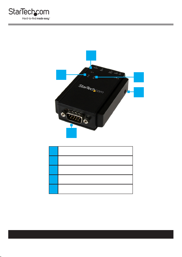
Front View
3
2
4
5
1
1 DB-9 Serial Port
2 Transmit LED
3 Power LED
4 Receive LED
5 Power Jack (10-30V DC)
To view manuals, videos, drivers, downloads, technical drawings, and more visit www.startech.com/support
4
Page 6
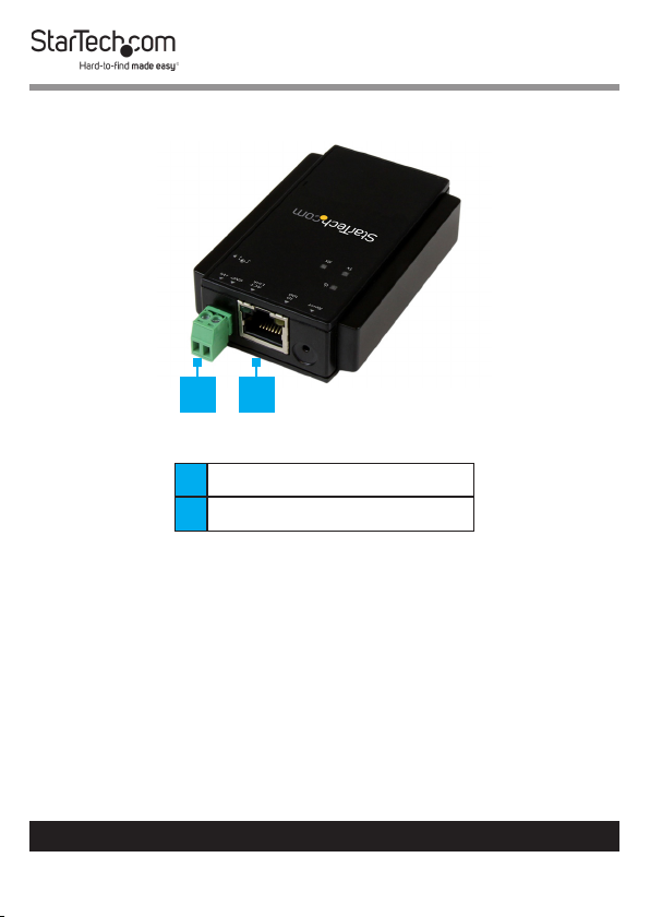
Rear View
1 2
1 Terminal Block (10-30V DC)
2 RJ45 Port
To view manuals, videos, drivers, downloads, technical drawings, and more visit www.startech.com/support
5
Page 7

DB-9 Serial Port Pinout
1 5
6 9
Pin 1 DCD Pin 6 DSR
Pin 2 RXD Pin 7 RTS
Pin 3 TXD Pin 8 CTS
Pin 4 DTR Pin 9 RI
Pin 5 GND
RJ45 Port Pinout
Pin 1 TX+ Pin 3 RX+
Pin 2 TX- Pin 6 RX-
To view manuals, videos, drivers, downloads, technical drawings, and more visit www.startech.com/support
6
Page 8

Product Information
Packaging Contents
• Serial over IP Device Server x 1
• DIN Rail Kit x 1
• Terminal Block x 1
• Universal Power Adapter (NA/UK/EU) and AU in Australia x 1
• Software CD x 1
• User Manual x 1
System Requirements
Cables
• RJ45 terminated Cat5 or higher Ethernet cabling
Network
• 10/100Mbps compatible Ethernet network
Operating System
• Windows® 8, 8.1, 7, Vista, XP, 2000, Windows® Server 2012,
2008 R2, 2003 or Linux (The included software does not
support Linux. To emulate a local COM port Linux users
would need to use Telnet.).
To view manuals, videos, drivers, downloads, technical drawings, and more visit www.startech.com/support
7
Page 9

Hardware Installation
DIN-Rail Bracket
Follow the below procedure to install the DIN-Rail Bracket to
the RS232 Device Server.
1. Align the DIN-Rail Bracket ush onto the back of the Device
Server.
2. Align the DIN-Rail Bracket Mounting Holes with the Pilot
Holes on the Device Server and use the Screws (x 2) to
secure the DIN-Rail Bracket to the Device Server.
Installing the Din Rail Bracket
DIN-Rail Mounting
Follow the below procedure to mount the device server to a
DIN-Rail.
1. Tilt the Device Server, making sure that the Metal Spring
located at the back is positioned on top of the DIN-Rail.
2. Push the Device Server towards the DIN-Rail, until it clicks.
To view manuals, videos, drivers, downloads, technical drawings, and more visit www.startech.com/support
8
Page 10

Connecting to Terminal Block Power
The Device Server is powered by either the Universal Power
Adapter (included), or a 2-wire 10~30V DC Power Source via
the Terminal Block (included).
1. Attach the included Universal Power Adapter to an AC
Electrical Outlet.
- or -
2. To use terminal block power, gently pull the Terminal Block
Connector Housing from the Device Server.
3. Using a Flat Head Screwdriver, loosen the Screws on the
Terminal Block Connectors.
4. Connect the Power and Ground wires from your DC Power
Source to the proper Terminal Block Connectors and
fasten the Screws. The terminals are marked on the device
server housing.
5. Reinsert the Terminal Block Connector Housing into the
Device Server.
Software Installation
1. Using a CAT5e/6 Cable connect the RJ45 Port on the
Device Server to your Local Area Network (LAN).
Note: Alternatively, you can also use a Crossover Cable to
connect the Device Server directly to your system for the
initial conguration.
2. Insert the provided CD into your DVD/CD-ROM drive.
To view manuals, videos, drivers, downloads, technical drawings, and more visit www.startech.com/support
9
Page 11

3. Browse to the folder \VCOM driver and execute the
vcomsetup.exe installer.
Browse to the VCOM Drive Folder
4. Follow the on-screen instructions to complete the
installation of the VCOM and WinPcap software.
Operation
1. Start the software by launching the VCOM shortcut.
2. Click the Search button in the VCOM screen to locate the
device.
To view manuals, videos, drivers, downloads, technical drawings, and more visit www.startech.com/support
10
Page 12

Click the Search Button
Note: If required, allow access to the software through the
Windows Firewall by clicking the Allow access button.
Windows Firewall screen
To view manuals, videos, drivers, downloads, technical drawings, and more visit www.startech.com/support
11
Page 13

3. When the device is found, congure the PC to the same IP
domain by clicking the Congure button. The default IP
address of the device is “192.168.1.1”.
Note: The default Gateway Address is “192.168.1.254”.
4. In the Input Attributes screen, enter the following:
• Account Name: admin
• Password: 00000
Input Attributes screen
5. When the device is connected, the Congure Dialog screen
will open to set your desired IP settings.
To view manuals, videos, drivers, downloads, technical drawings, and more visit www.startech.com/support
12
Page 14

Congure Dialog screen
6. When your settings have been customized, click the OK
button at the bottom of the screen.
To view manuals, videos, drivers, downloads, technical drawings, and more visit www.startech.com/support
13
Page 15

Specications
Interface Serial
Industry Standards IEEE 802.3, IEEE 802.3u
Ports 1
1x DB-9 (9 pin; D-Sub) Male
Connectors
Auto MDIX Yes
Compatible
Networks
Data Bits 5, 6, 7, 8
Flow Control RTS/CTS, None
Max Baud Rate 230.4 Kbps
Parity None, Even, Odd, Space, Mark
Remote
Management Ability
Serial Protocols RS-232
Stop Bits 1, 2, 1.5
Supported Protocols
1x RJ-45 Female
1x Terminal Block (2 wire)
1x DC Power
10/100 Mbps
Yes
Telnet, VCOM, TCP Server,
TCP Client, UDP, HTTP,DHCP,
ICMP(PING), Static IP, ARP
To view manuals, videos, drivers, downloads, technical drawings, and more visit www.startech.com/support
14
Page 16

Enclosure Type Plastic
Product Dimensions
(LxWxH)
86mm x 54mm x 23mm
1x Power
1x Tx
LED Indicator(s)
1x Rx
1x 10/100 Mbps Indicator
1x Link / Activity
Terminal Block: 10~30V DC (2
Power Input
wire)
DC Jack: 10~30V DC 3.5mm
Power Consumption 1.45W Max
Enclosure Material Plastic
Operating
Temperature
0°C to 60°C (32°F to 140°F)
Storage Temperature -10°C to 70°C (-14°F to 158°F)
Humidity 0~90% RH
Product Weight 2.29 oz (65 g)
Windows® 8 / 8.1 (32/64bit),
Compatible
Operating Systems
7 (32/64), Vista(32/64),
XP(32/64), 2000, Windows®
Server 2012, 2008 R2,
2003(32/64)
To view manuals, videos, drivers, downloads, technical drawings, and more visit www.startech.com/support
15
Page 17

Warranty Information
This product is backed by a two-year warranty.
For further information on product warranty terms and conditions, please refer
to www.startech.com/warranty.
Limitation of Liability
In no event shall the liability of StarTech.com Ltd. and StarTech.com USA LLP (or
their ocers, directors, employees or agents) for any damages (whether direct
or indirect, special, punitive, incidental, consequential, or otherwise), loss of
prots, loss of business, or any pecuniary loss, arising out of or related to the use
of the product exceed the actual price paid for the product.
Some states do not allow the exclusion or limitation of incidental or
consequential damages. If such laws apply, the limitations or exclusions
contained in this statement may not apply to you.
To view manuals, videos, drivers, downloads, technical drawings, and more visit www.startech.com/support
16
16
Page 18

Hard-to-nd made easy. At StarTech.com, that isn’t a slogan.
It’s a promise.
StarTech.com is your one-stop source for every connectivity part you need.
From the latest technology to legacy products — and all the parts that bridge
the old and new — we can help you nd the parts that connect your solutions.
We make it easy to locate the parts, and we quickly deliver them wherever they
need to go. Just talk to one of our tech advisors or visit our website. You’ll be
connected to the products you need in no time.
Visit www.startech.com for complete information on all StarTech.com products
and to access exclusive resources and time-saving tools.
StarTech.com is an ISO 9001 Registered manufacturer of connectivity and
technology parts. StarTech.com was founded in 1985 and has operations in the
United States, Canada, the United Kingdom and Taiwan servicing a worldwide
market.
Reviews
Share your experiences using StarTech.com products, including product
applications and setup, what you love about the products, and areas for
improvement.
StarTech.com Ltd.
45 Artisans Cres.
London, Ontario
N5V 5E9
Canada
FR: startech.com/fr
DE: startech.com/de
StarTech.com LLP
2500 Creekside Pkwy.
Lockbourne, Ohio
43137
U.S.A.
ES: startech.com/es
NL: startech.com/nl
StarTech.com Ltd.
Unit B, Pinnacle
15 Gowerton Rd.,
Brackmills
Northampton
NN4 7BW
United Kingdom
IT: startech.com/it
JP: startech.com/jp
To view manuals, videos, drivers, downloads, technical drawings, and more visit www.startech.com/support
 Loading...