

Page 1
A/V Connectivity Module for BOX4MODULE and
BEZ4MOD
Actual product may vary from photos
User Manual
SKU#: MOD4AVHD
For the latest information and specications visit
www.startech.com/MOD4AVHD
Manual Revision: 03/01/2019
Page 2

Compliance Statements
FCC Compliance Statement
This equipment has been tested and found to comply with the limits for a Class
B digital device, pursuant to part 15 of the FCC Rules. These limits are designed
to provide reasonable protection against harmful interference in a residential
installation. This equipment generates, uses and can radiate radio frequency
energy and, if not installed and used in accordance with the instructions, may
cause harmful interference to radio communications. However, there is no
guarantee that interference will not occur in a particular installation. If this
equipment does cause harmful interference to radio or television reception,
which can be determined by turning the equipment o and on, the user is
encouraged to try to correct the interference by one or more of the following
measures:
• Reorient or relocate the receiving antenna
• Increase the separation between the equipment and receiver
• Connect the equipment into an outlet on a circuit dierent from that to
which the receiver is connected
• Consult the dealer or an experienced radio/TV technician for help
Use of Trademarks, Registered Trademarks, and other
Protected Names and Symbols
This manual may make reference to trademarks, registered trademarks, and
other protected names and/or symbols of third-party companies not related in
any way to StarTech.com. Where they occur these references are for illustrative
purposes only and do not represent an endorsement of a product or service
by StarTech.com, or an endorsement of the product(s) to which this manual
applies by the third-party company in question. Regardless of any direct
acknowledgement elsewhere in the body of this document, StarTech.com
hereby acknowledges that all trademarks, registered trademarks, service marks,
and other protected names and/or symbols contained in this manual and
related documents are the property of their respective holders.
To view manuals, videos, drivers, downloads, technical drawings, and more visit www.startech.com/support
i
Page 3

Industry Canada Statement
This Class B digital apparatus complies with Canadian ICES-003.
Cet appareil numérique de la classe [B] est conforme à la norme NMB-003 du
Canada.
CAN ICES-3 (B)/NMB-3(B)
This device complies with Industry Canada licence-exempt RSS standard(s).
Operation is subject to the following two conditions:
(1) This device may not cause interference, and (2) This device must accept any
interference, including interference that may cause undesired operation of the
device.
To view manuals, videos, drivers, downloads, technical drawings, and more visit www.startech.com/support
ii
Page 4

Safety Statements
Safety Measures
• Wiring terminations should not be made with the product and/or electric
lines under power.
• Product installation and/or mounting should be completed by a certied
professional as per the local safety and building code guidelines.
• Cables (including power and charging cables) should be placed and routed
to avoid creating electric, tripping or safety hazards.
Mesures de sécurité
• Les terminaisons de câblâge ne doivent pas être eectuées lorsque le produit
et/ou les câbles électriques sont sous tension.
• L’installation et/ou le montage du produit doit être réalisé par un
professionnel certié et dans le respect des normes locales et du code de
construction local.
• Les câbles (y compris les câbles d’alimentation et de chargement) doivent
être placés et acheminés de façon à éviter tout risque électrique, de chute ou
de sécurité
安全対策
• 電源が入っている状態の製品または電線の終端処理を行わないでくださ
い。
• 製品の設置やマウントは、使用地域の安全ガイドラインおよび建築基準に
従い、有資格の専門業者が行うようにしてください。
• ケーブル(電源ケーブルと充電ケーブルを含む)は、適切な配置と引き回し
を行い、電気障害やつまづきの危険性など、安全上のリスクを回避するよう
にしてください 。
Misure di sicurezza
• I terminiali dei li elettrici non devono essere realizzate con il prodotto e/o le
linee elettriche sotto tensione.
• L’installazione e/o il montaggio dei prodotti devono essere eseguiti da un
tecnico professionale certicato che conosca le linee guida locali sulle norme
edilizie e sulla sicurezza.
• I cavi (inclusi i cavi di alimentazione e di ricarica) devono essere posizionati
e stesi in modo da evitare pericoli di inciampo, rischi di scosse elettriche o
pericoli per la sicurezza.
To view manuals, videos, drivers, downloads, technical drawings, and more visit www.startech.com/support
iii
Page 5

Säkerhetsåtgärder
• Montering av kabelavslutningar får inte göras när produkten och/eller
elledningarna är strömförda.
• Installation och/eller montering får endast göras av behöriga yrkespersoner
och enligt gällande lokala förordningar för säkerhet och byggnormer.
• Kablar (inklusive elkablar och laddningskablar) ska dras och placeras på så
sätt att risk för snubblingsolyckor och andra olyckor kan undvikas.
Warning Statements
Make sure to assemble this product according to the instructions. Failure to do
so might result in personal injury or property damage.
Never use this product if parts are missing or damaged.
To view manuals, videos, drivers, downloads, technical drawings, and more visit www.startech.com/support
iv
Page 6

Table of Contents
Compliance Statements ........................................................................i
Safety Statements ..................................................................................iii
Warning Statements ..............................................................................iv
Product Diagram ....................................................................................1
Top View .......................................................................................................................................................1
Bottom View ................................................................................................................................................2
Side View ...................................................................................................................................................... 3
Product Information ..............................................................................4
Package Contents ..................................................................................................................................... 4
Requirements ............................................................................................................................................. 4
Installation ..............................................................................................5
Mounting ..................................................................................................................................................... 5
Powering the Module .............................................................................................................................. 6
Connecting Devices to the Bottom of the Module ...........................7
RJ45 Passthrough Port ............................................................................................................................ 7
HDMI Out Port ............................................................................................................................................ 7
Audio Out Port ........................................................................................................................................... 8
DC 5V 2A Port ............................................................................................................................................. 8
DisplayPort In Ports .................................................................................................................................. 8
HDMI In Port ................................................................................................................................................ 8
Audio In Port ............................................................................................................................................... 9
VGA In Port .................................................................................................................................................. 9
To view manuals, videos, drivers, downloads, technical drawings, and more visit www.startech.com/support
Page 7

Connecting Devices to the Top of the Module .................................. 9
RJ45 Passthrough Port ............................................................................................................................ 9
VGA In Port .................................................................................................................................................. 10
Audio In Port ............................................................................................................................................... 10
HDMI In Port ................................................................................................................................................ 10
DisplayPort In Port .................................................................................................................................... 10
Operation ................................................................................................11
LED Indicators............................................................................................................................................. 11
Reset Button ................................................................................................................................................ 11
Automatic Video Switching .................................................................................................................. 11
Conguration ..........................................................................................12
Conguring a Display .............................................................................................................................. 12
Display Preferences ..................................................................................................................................13
Maximum Resolution Chart .................................................................. 14
Connectivity Diagram ...........................................................................15
To view manuals, videos, drivers, downloads, technical drawings, and more visit www.startech.com/support
Page 8
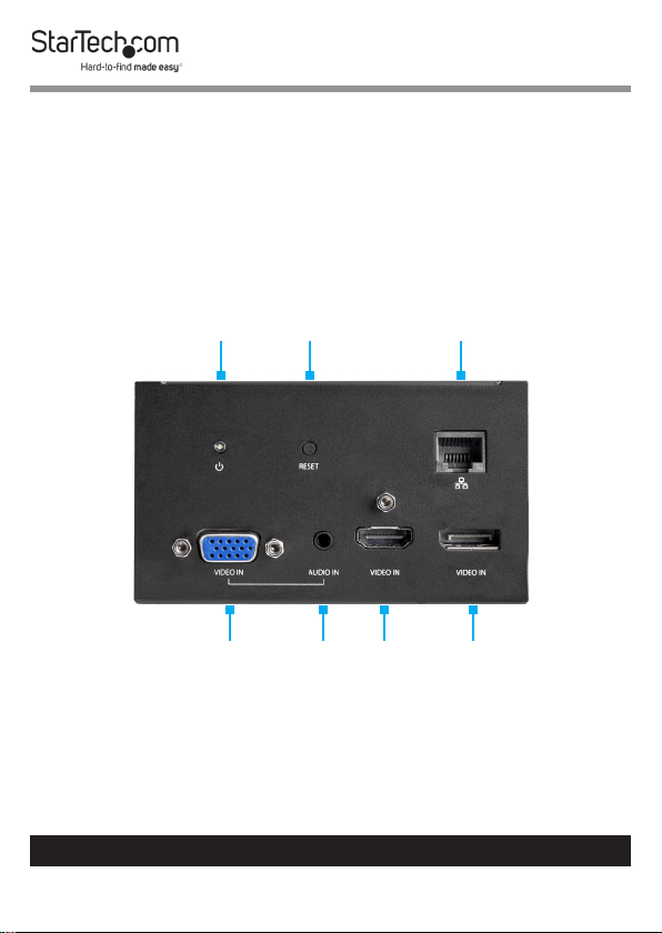
Product Diagram
Actual product may vary from photos.
Top View
Power
LED
VGA In
Port
To view manuals, videos, drivers, downloads, technical drawings, and more visit www.startech.com/support
Reset
Button
Audio
In Port
HDMI
In Port
1
RJ45
Passthrough
Port
DisplayPort
In Port
Page 9

Bottom View
RJ45
Passthrough
Port
DisplayPort
In Port
To view manuals, videos, drivers, downloads, technical drawings, and more visit www.startech.com/support
HDMI
In Port
HDMI
Audio
In Port
2
Out
Port
Audio
Out
Port
VGA In
Port
DC
5V 2A
Port
Page 10

Side View
Mounting Holes
Mounting
Holes
To view manuals, videos, drivers, downloads, technical drawings, and more visit www.startech.com/support
3
Page 11

Product Information
Package Contents
• A/V Module x 1
• Universal Power Adapter x 1
• Power Clips (NA, EU, UK) x 3
• Mounting Bracket x 1
• Mounting Bracket Screws (M5x20 mm) x 4
• Module Screws ( #6-32 x 3/16’’) x 8
• Quick-Start Guide x 1
Requirements
For the latest requirements, please visit
www.startech.com/MOD4AVHD.
Installation:
• Mounting Bracket x 1
• Mounting Bracket Screws (M5x20 mm) x 4
• Module Screws (#6-32 x 3/16”) x 4
• Writing Utensil x 1
• Phillips Head Screwdriver x 1
Laptop:
• HDMI, DisplayPort, or VGA Video Output Devices
Display:
• HDMI Enabled Display Device (up to 4K@30Hz) x 1
• HDMI Cable x 1
To view manuals, videos, drivers, downloads, technical drawings, and more visit www.startech.com/support
4
Page 12

Devices:
• Network Device x 1
• CAT5e/6 Cables x 2
• Audio Input Devices x 2
• Audio Output Device x 1
Power
• Power Source (e.g. Wall Outlet, Power Bar, etc.) x 1
Installation
Warning: Test the functionality of MOD4AVHD with your
equipment to ensure compatibility before installation.
Note: StarTech.com is not responsible for any damages
related to the installation of this product.
See the Installation section in the Modular Table Box
(BOX4MODULE) or Single-Module Table Box (BEZ4MOD)
User Manual for instructions on how to install a Module
(found at www.startech.com/BEZ4MOD or www.startech.com/
BOX4MODULE - Table Boxes are sold separately).
Mounting
Using the Included Mounting Bracket
Note: Before mounting the Module, consider the desired
orientation of the Ports (front and rear).
1. Align the Mounting Bracket with four Mounting Holes on
the Module.
Note: There are four Mounting Holes on each side of the
Module, which allows you to mount the Module in one of
two dierent positions.
To view manuals, videos, drivers, downloads, technical drawings, and more visit www.startech.com/support
5
Page 13

2. Insert the Module Screws (x4) through the Mounting
Bracket and into the Mounting Holes.
3. Tighten the Module Screws using a Phillips Head
Screwdriver. Do not over-tighten the Module Screws.
4. Before installing the Mounting Bracket on or under the
Mounting Surface, measure and position the Mounting
Bracket in the desired location. The Module can be
mounted on a vertical or horizontal Mounting Surface.
5. (Optional) Depending on the Mounting Surface you are
using to install the product, you may need to drill pilot holes
prior to installing the Mounting Bracket Screws into the
Mounting Surface.
6. Mark the location of the Mounting Holes using a Writing
Utensil. These marks can be used as a guide to indicate
where the Mounting Bracket Screws will be installed in the
surface.
7. Install the Mounting Bracket Screws (x4) through the
Mounting Bracket and into the Mounting Surface, using
a Phillips Head Screwdriver. Do not over-tighten the
Mounting Bracket Screws.
Warning: To prevent the Mounting Bracket Screws from
penetrating the opposite side of the Mounting Surface, be
conscious of the length of the Mounting Bracket Screws
compared to the depth of the Mounting Surface.
Powering the Module
1. On the bottom of the A/V Module, connect the Universal
Power Adapter to the DC 5V 2A Port.
To view manuals, videos, drivers, downloads, technical drawings, and more visit www.startech.com/support
6
Page 14

2. Tighten the Lock Screw on the Universal Power Adapter’s
Barrel Connector, to prevent the cable from accidentally
disconnecting from the A/V Module.
3. Connect the other end of the Universal Power Adapter to
an appropriate Power Source.
Connecting Devices to the Bottom of the
Module
Tip: Devices being used in your boardroom can be
connected to the bottom of MOD4AVHD to reduce table
top cable clutter.
RJ45 Passthrough Port
The RJ45 Passthrough Port is used to connect a Network
Device to the A/V Module.
1. Connect a CAT5e/6 Cable’s RJ45 Connector to the RJ45
Passthrough Port on the A/V Module.
2. Connect the other RJ45 Connector on the CAT5e/6 Cable
to an RJ45 Port on a Network Device.
HDMI Out Port
The HDMI Out Port is used to connect an HDMI Enabled
Display Device to the A/V Module.
1. Connect an HDMI Cable to the HDMI Out Port on the AV
Module.
2. Connect the other end of the HDMI Cable to an HDMI Port
on your HDMI Enabled Display Device.
To view manuals, videos, drivers, downloads, technical drawings, and more visit www.startech.com/support
7
Page 15

Audio Out Port
The Audio Out Port is used to connect an Audio Device (e.g.
Headphones, Speakers, etc.) to the A/V Module.
1. Connect a 3.5 mm Audio Cable to the Audio Out Port on
the A/V Module.
2. If connecting speakers, connect the other end of the 3.5 mm
Audio Cable to the Audio In Port on the Audio Device.
DC 5V 2A Port
See Powering the Module.
DisplayPort In Ports
The DisplayPort Ports enable you to connect DisplayPort
Video Source Devices to the A/V Module for use with the
connected Host Computer.
1. Connect a DisplayPort Cable to the DisplayPort Port on
the A/V Module.
2. Connect the other end of the DisplayPort Cable to a
DisplayPort port on the DisplayPort Video Source Devices.
HDMI In Port
The HDMI In Port is used to connect a Video Source Device to
the A/V Module.
1. Connect an HDMI Cable to the HDMI In Port on the A/V
Module.
2. Connect the other end of the HDMI Cable to an HDMI port
on a Source Device.
To view manuals, videos, drivers, downloads, technical drawings, and more visit www.startech.com/support
8
Page 16

Audio In Port
The Audio In Port is used to connect an Audio Source Device
to the A/V Module.
1. Connect a 3.5 mm Audio Cable to the Audio In Port on the
A/V Module.
2. Connect the other end of the 3.5 mm Audio Cable to the
Audio Out Port on the Audio Source Device.
VGA In Port
The VGA In Port is used to connect a Video Source Device to
the A/V Module.
1. Connect a VGA Cable to the VGA In Port on the A/V
Module.
2. Connect the other end of the VGA Cable to a VGA Output
Port on the Video Source Device.
Connecting Devices to the
Top of the Module
RJ45 Passthrough Port
The RJ45 Passthrough Port is used to connect a Network
Device to the A/V Module.
1. Connect a CAT5e/6 Cable’s RJ45 Connector to the RJ45
Passthrough Port on the A/V Module.
2. Connect the other RJ45 Connector on the CAT5e/6 Cable
to an RJ45 Port on a Network Device.
To view manuals, videos, drivers, downloads, technical drawings, and more visit www.startech.com/support
9
Page 17

VGA In Port
The VGA In Port is used to connect a Video Source Device to
the A/V Module.
1. Connect a VGA Cable to the VGA In Port on the A/V
Module.
2. Connect the other end of the VGA Cable to a VGA Output
Port on the Video Source Device.
Audio In Port
The Audio In Port is used to connect an Audio Source Device
to the A/V Module.
1. Connect a 3.5 mm Audio Cable to the Audio In Port on the
A/V Module.
2. Connect the other end of the 3.5 mm Audio Cable to the
Audio Out Port on the Audio Source Device.
HDMI In Port
The HDMI In Port is used to connect a Source Device to the
A/V Module.
1. Connect an HDMI Cable to the HDMI In Port on the A/V
Module.
2. Connect the other end of the HDMI Cable to an HDMI port
on a Source Device.
DisplayPort In Port
The DisplayPort Port enables you to connect a Display Device
to the A/V Module for use with the connected Host Computer.
To view manuals, videos, drivers, downloads, technical drawings, and more visit www.startech.com/support
10
Page 18

1. Connect a DisplayPort Cable to the DisplayPort Port on
the A/V Module.
2. Connect the other end of the DisplayPort Cable to a
DisplayPort port on the Video Source Device.
Operation
LED Indicators
Power
Solid LED (White)
• Indicates that the A/V Module is active (the Universal Power
Adapter is correctly connected to an AC Electrical Outlet).
LED O
• Indicates that the Universal Power Adapter is not correctly
connected to an AC Electrical Outlet or the A/V Module is
not receiving power from the AC Electrical Outlet.
Reset Button
Press and release the Reset Button to reset the EDID settings.
Automatic Video Switching
Automatic video switching allows you to connect an HDMI, DP
or VGA Video Source to an HDMI Display or Projector without
the hassle of menu and input selections by automatically
switching to the most recently connected or powered-on
Source.
To view manuals, videos, drivers, downloads, technical drawings, and more visit www.startech.com/support
11
Page 19

Conguration
Conguring a Display
Video output capabilities are dependent on the video card and
hardware specications of the connected Host Computer and
Displays.
Note: Navigating to the Settings screen will vary depending
on the operating system (OS) or operating system version
running on the host laptop.
Windows:
1. Right-click on the Desktop and select Screen Resolution or
Display Settings (depending on the OS version) from the
pop-up menu.
2. Adjust the Display Order, Screen Resolution, Orientation
and Display Mode as needed.
macOS:
1. Click the Apple Icon and select System Preferences.
2. Click Displays to open the Display Preferences screen.
3. On the Display Preferences screen, you can congure your
system’s display settings.
To view manuals, videos, drivers, downloads, technical drawings, and more visit www.startech.com/support
12
Page 20

Display Preferences
Orientation:
• Landscape: Sets the Display in a horizontal orientation.
• Portrait: Sets the Display in a vertical orientation.
Multiple Displays:
• Extend desktop to this display: Extends your desktop area
across multiple Displays, enabling you to move applications
from one Display to the other.
• Duplicate desktop on: Duplicates the desktop marked as
the main Display onto the selected Display.
• Disconnect this display: Disconnects the selected Display.
Make this my main display:
• Select this check box to mark the current Display as the main
or primary Display. When using the other Display types, the
main Display will either be extended (Extend desktop to this
display) or Duplicated (Duplicate this display).
Resolution:
• The number of pixels rendered on the Display measure as
width x height (e.g. 1920 x 1080).
To view manuals, videos, drivers, downloads, technical drawings, and more visit www.startech.com/support
13
Page 21

Maximum Resolution Chart
Input Port
Top HDMI In
Port
Top
DisplayPort
In Port
Top VGA In
and Audio In
Ports
Bottom
HDMI In Port
Bottom
DisplayPort
In Port
Bottom VGA
In and Audio
In Ports
HDMI Output
Resolution
Up to 3840
x 2160 30Hz
+ 7.1/5.1/2
channel audio
Up to 3840
x 2160 30Hz
+ 7.1/5.1/2
channel audio
1920 X 1080
60Hz + 2
channel audio
Up to 3840
x 2160 30Hz
+ 7.1/5.1/2
channel audio
Up to 3840
x 2160 30Hz
+ 7.1/5.1/2
channel audio
1920 X 1080
60Hz + 2
channel audio
CAT5e/6 Video Output
Resolution
Up to 3840 x 2160 30Hz with
35 m extension / 1920 X 1080
60Hz with 70 m extension +
7.1/5.1/2 channel audio
Up to 3840 x 2160 30Hz with
35 m extension / 1920 X 1080
60Hz with 70 m extension +
7.1/5.1/2 channel audio
1920 X 1080 60Hz with 70 m
extension + 2 channel audio
Up to 3840 x 2160 30Hz with
35 m extension / 1920 X 1080
60Hz with 70 m extension +
7.1/5.1/2 channel audio
Up to 3840 x 2160 30Hz with
35 m extension / 1920 X 1080
60Hz with 70 m extension +
7.1/5.1/2 channel audio
1920 X 1080 60Hz with 70 m
extension + 2 channel audio
To view manuals, videos, drivers, downloads, technical drawings, and more visit www.startech.com/support
14
Page 22

Connectivity Diagram
To view manuals, videos, drivers, downloads, technical drawings, and more visit www.startech.com/support
15
Page 23

Warranty Information
This product is backed by a two-year warranty.
For further information on product warranty terms and conditions, please refer
to www.startech.com/warranty.
Limitation of Liability
In no event shall the liability of StarTech.com Ltd. and StarTech.com USA LLP (or
their ocers, directors, employees or agents) for any damages (whether direct
or indirect, special, punitive, incidental, consequential, or otherwise), loss of
prots, loss of business, or any pecuniary loss, arising out of or related to the use
of the product exceed the actual price paid for the product.
Some states do not allow the exclusion or limitation of incidental or
consequential damages. If such laws apply, the limitations or exclusions
contained in this statement may not apply to you.
To view manuals, videos, drivers, downloads, technical drawings, and more visit www.startech.com/support
16
16
Page 24

Hard-to-nd made easy. At StarTech.com, that isn’t a slogan.
It’s a promise.
StarTech.com is your one-stop source for every connectivity part you need.
From the latest technology to legacy products — and all the parts that bridge
the old and new — we can help you nd the parts that connect your solutions.
We make it easy to locate the parts, and we quickly deliver them wherever they
need to go. Just talk to one of our tech advisors or visit our website. You’ll be
connected to the products you need in no time.
Visit www.startech.com for complete information on all StarTech.com products
and to access exclusive resources and time-saving tools.
StarTech.com is an ISO 9001 Registered manufacturer of connectivity and
technology parts. StarTech.com was founded in 1985 and has operations in the
United States, Canada, the United Kingdom and Taiwan servicing a worldwide
market.
Reviews
Share your experiences using StarTech.com products, including product
applications and setup, what you love about the products, and areas for
improvement.
StarTech.com Ltd.
45 Artisans Cres.
London, Ontario
N5V 5E9
Canada
FR: fr.startech.com
DE: de.startech.com
StarTech.com LLP
2500 Creekside Pkwy.
Lockbourne, Ohio
43137
U.S.A.
ES: es.startech.com
NL: nl.startech.com
StarTech.com Ltd.
Unit B, Pinnacle
15 Gowerton Rd.,
Brackmills
Northampton
NN4 7BW
United Kingdom
IT: it.startech.com
JP: jp.startech.com
To view manuals, videos, drivers, downloads, technical drawings, and more visit www.startech.com/support
 Loading...