

Page 1
10-Port L2 Managed Gigabit Ethernet
Switch with 2 SFP Slots - Rack Mountable
IES101002SFP
*actual product may vary from photos
DE: Bedienungsanleitung - de.startech.com
FR: Guide de l'utilisateur - fr.startech.com
ES: Guía del usuario - es.startech.com
IT: Guida per l'uso - it.startech.com
NL: Gebruiksaanwijzing - nl.startech.com
PT: Guia do usuário - pt.startech.com
For the latest information, technical specications, and support for
this product, please visit www.startech.com/IES101002SFP.
Manual Revision: 05/25/2015
Page 2

FCC Compliance Statement
This equipment has been tested and found to comply with the limits for a Class A digital
device, pursuant to Part 15 of the FCC rules. These limits are designed to provide reasonable
protection against harmful interference when the equipment is operated in a commercial
environment. This equipment generates, uses and can radiate radio frequency energy and,
if not installed and used in accordance with the instruction manual, may cause harmful
interference to radio communications. Operation of this equipment in a residential area is
likely to cause harmful interference in which case the user will be required to correct the
interference at his own expense.
This device complies with part 15 of the FCC Rules. Operation is subject to the following
two conditions: (1) This device may not cause harmful interference, and (2) this device must
accept any interference received, including interference that may cause undesired operation.
Changes or modications not expressly approved by StarTech.com could void the user’s
authority to operate the equipment.
Use of Trademarks, Registered Trademarks, and other Protected Names and Symbols
This manual may make reference to trademarks, registered trademarks, and other
protected names and/or symbols of third-party companies not related in any way to
StarTech.com. Where they occur these references are for illustrative purposes only and do not
represent an endorsement of a product or service by StarTech.com, or an endorsement of the
product(s) to which this manual applies by the third-party company in question. Regardless
of any direct acknowledgement elsewhere in the body of this document, StarTech.com hereby
acknowledges that all trademarks, registered trademarks, service marks, and other protected
names and/or symbols contained in this manual and related documents are the property of
their respective holders.
Instruction Manual
Page 3

Table of Contents
Product diagram ....................................................................................1
Front view ....................................................................................................................................................1
Rear view ...................................................................................................................................................... 1
Introduction ............................................................................................2
Packaging contents .................................................................................................................................. 2
Features ........................................................................................................................................................2
Specications.............................................................................................................................................. 4
Performances .............................................................................................................................................. 4
LED indicators ............................................................................................................................................. 5
Web management ..................................................................................6
Congure the switch for the rst time .............................................................................................. 6
Change your password ........................................................................................................................... 7
About the setting options in the Web management UI..............................................................7
Changing the Conguration settings .................................................23
Change the System Information settings .........................................................................................23
Change the System IP settings ............................................................................................................. 23
Change the System IPv6 settings ........................................................................................................ 24
Change the NTP Conguration settings ........................................................................................... 25
Change the Time settings ......................................................................................................................25
Change the Log settings ........................................................................................................................ 27
Change the LED settings ........................................................................................................................ 27
Change the EEE settings ......................................................................................................................... 28
Change the Port settings ........................................................................................................................ 29
Change the User settings ....................................................................................................................... 30
Change the Privilege Levels settings ................................................................................................. 31
Change the Authentication Method settings ................................................................................. 31
Instruction Manual
i
Page 4

Set up the Secure Shell management interface ............................................................................ 32
Enable HTTPS ............................................................................................................................................. 33
Congure the access management settings ................................................................................... 33
Congure the SNMP settings ................................................................................................................ 34
Change the SNMPv3 community conguration settings ........................................................... 35
Change the SNMPv3 User settings ..................................................................................................... 36
Change the SNMPv3 Group settings ................................................................................................. 37
Change the SNMPv3 View settings .....................................................................................................38
Change the SNMPv3 Access settings ................................................................................................. 38
Change the RMON Statistics settings ................................................................................................ 39
Change the RMON History settings.................................................................................................... 40
Change the RMON Alarm settings ...................................................................................................... 41
Change the RMON Event settings ....................................................................................................... 43
Change the Port Security Limit Control settings ........................................................................... 44
Change the Network Access settings ................................................................................................ 46
Change the Ports settings ...................................................................................................................... 52
Change the Rate Limiters settings ...................................................................................................... 53
Change the Access Control List settings ...........................................................................................54
Change the Snooping Conguration settings ............................................................................... 56
Change the Relay settings ..................................................................................................................... 57
Change the IP Source Guard settings ................................................................................................ 59
Change the Static Table settings ......................................................................................................... 60
Change the Conguration settings .................................................................................................... 60
Change the Static ARP Inspections Table settings ........................................................................61
Change the Authentication Server Conguration settings ....................................................... 61
Change the Static settings ..................................................................................................................... 62
Change the LACP settings ..................................................................................................................... 63
Change the Loop Protection settings ................................................................................................ 65
Change the Spanning Tree settings ................................................................................................... 66
Change the MSTI Mapping settings ................................................................................................... 67
Change the MSTI Priorities settings ................................................................................................... 68
Instruction Manual
ii
Page 5

Change the CIST ports settings ............................................................................................................ 68
Change the MSTI Ports settings ........................................................................................................... 70
Change the MVR settings ....................................................................................................................... 71
Change the IGMP Snooping Conguration settings .................................................................... 73
Change the VLAN Conguration settings ........................................................................................74
Change the Port Group Filtering settings ........................................................................................ 75
Change the Basic Conguration settings ......................................................................................... 76
Change the VLAN Conguration settings ........................................................................................77
Change the MLD Conguration settings .......................................................................................... 78
Change the LLDP settings ...................................................................................................................... 79
Change the LLDP-MED settings ........................................................................................................... 81
Change the MAC Table settings ........................................................................................................... 88
Change the VLAN Memberships settings.........................................................................................89
Change the Ports settings ...................................................................................................................... 89
Change PVLAN Membership settings ............................................................................................... 91
Change the Port Isolation settings ..................................................................................................... 92
Change the MAC-based VLAN settings .............................................................................................92
Change the Protocol to Group settings ............................................................................................93
Change the Group to VLAN settings ..................................................................................................94
Change the IP subnet-based VLAN settings ....................................................................................95
Change the Voice VLAN Conguration settings ............................................................................ 96
Change the OUI settings ........................................................................................................................ 97
Change the Port Classication settings ............................................................................................ 98
Change the Port Policing settings.......................................................................................................99
Change the Port Scheduler settings .................................................................................................. 100
Change the Port Shaping settings ...................................................................................................... 101
Change the Port Tag Remarking settings ......................................................................................... 101
Change the Port DSCP settings ............................................................................................................ 102
Change the DSCP-Based QoS settings .............................................................................................. 103
Change the DSCP Translation settings ..............................................................................................104
Change the DSCP Classication settings .......................................................................................... 105
Instruction Manual
iii
Page 6

Change the QoS Control List settings ................................................................................................ 105
Change the Storm Control settings .................................................................................................... 107
Change the Mirror Conguration settings .......................................................................................108
Change the UPnP settings ..................................................................................................................... 108
Change the sFlow settings.....................................................................................................................109
Changing the Monitor settings ............................................................112
Change the Information settings ........................................................................................................ 112
Change the CPU Load settings .............................................................................................................113
Change the Log settings ........................................................................................................................ 113
Change the Detailed Log settings ...................................................................................................... 114
Change the Detailed Log settings ...................................................................................................... 115
Change the Trac Overview settings ................................................................................................115
Change the QoS Statistics settings ..................................................................................................... 116
Change the QCL Status settings .......................................................................................................... 117
Change the Detailed Statistics settings ............................................................................................ 118
Change the ACL Status settings ...........................................................................................................120
Change the Switch settings................................................................................................................... 121
Change the Port settings ........................................................................................................................ 122
Change the Switch settings................................................................................................................... 123
Change the NAS Statistics Port settings ........................................................................................... 124
Change the ACL Status settings ...........................................................................................................128
Change the Snooping Statistics settings .......................................................................................... 130
Change the Relay Statistics settings...................................................................................................131
Change the ARP Inspection settings .................................................................................................. 132
Change the IP Source Guard settings ................................................................................................ 133
Change the RADIUS Overview settings ............................................................................................ 133
Change the RADIUS Details settings .................................................................................................. 134
Change the RMON Statistics settings ................................................................................................ 135
Change the RMON History settings.................................................................................................... 137
Change the Alarm settings .................................................................................................................... 138
Instruction Manual
iv
Page 7

Change the System Status settings .................................................................................................... 139
Change the Port Status settings .......................................................................................................... 140
Change the Port Statistics settings ..................................................................................................... 141
Change the Loop Protection settings ................................................................................................ 141
Change the Bridge Status settings ..................................................................................................... 142
Change the Port Status settings .......................................................................................................... 144
Change the Port Statistics settings ..................................................................................................... 144
Change the Statistics settings .............................................................................................................. 145
Change the MVR Channel Groups settings ..................................................................................... 146
Change the MVR SFM Information settings .................................................................................... 146
Change the Snooping Status settings ............................................................................................... 147
Change the Groups Information settings ........................................................................................ 148
Change the IPv4 SFM Information settings ..................................................................................... 149
Change the MLD Status settings ......................................................................................................... 150
Change the Groups Information settings ........................................................................................ 151
Change the IPv6 SFM Information settings ..................................................................................... 151
Change the Neighbours settings ........................................................................................................ 152
Change the LLDP-MED Neighbours settings .................................................................................. 153
Change the EEE settings ......................................................................................................................... 157
Change the Port Statistics settings ..................................................................................................... 159
Change the MAC Table settings ........................................................................................................... 160
Change the VLAN Membership settings .......................................................................................... 160
Change the VLAN Port settings ............................................................................................................ 162
Change the MAC-Based VLAN settings .............................................................................................163
Change the sFlow settings.....................................................................................................................164
Testing the connectivity of the network ............................................166
Change the Ping settings ....................................................................................................................... 166
Change the Ping6 settings.....................................................................................................................166
About device maintenance...................................................................167
Restart the device ..................................................................................................................................... 167
Instruction Manual
v
Page 8

Restore the factory default settings ................................................................................................... 167
Update your rmware .............................................................................................................................167
Change the Image Select settings ...................................................................................................... 168
Save the switch conguration to an XML le..................................................................................168
Restore the switch to a backup conguration ................................................................................168
Technical Support .................................................................................. 169
Warranty Information ............................................................................169
Instruction Manual
vi
Page 9
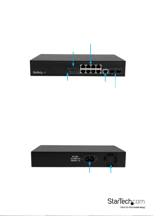
Product diagram
Front view
Gigabit Ethernet RJ45 ports
LED indicators
Rear view
Instruction Manual
Reset button
Console RJ45 port
DC power
1
Gigabit Open SFP slots
Cooling fan
Page 10

Introduction
This switch is a Web Smart switch equipped with 8 ports 10/100/1000BaseT(X)
and 2 ports Gigabit SFP open slots, and provides a broad range of features for
Layer2 switching. It was designed for easy installation and high performance in an
environment where the trac is on the network and the number of users increases
continuously. The smart and ecient power design is designed to improve power
usage.
Packaging contents
• 1 x 10-port Gigabit Ethernet switch with 2 open SFP slots
• 2 x mounting brackets (1 set)
• 3 x power cords (NA/UK/EU)
• 1 x instruction manual
Features
Feature Description
Dual images Prevents any kind of upgrading process failure
IPv4 Supports IPv4 addressing, management, and Quality of
IPv6 Supports IPv6 addressing, management, and Multicast
Power saving LED power management
Security Private VLAN (static)
Service (QoS)
Listener Discovery (MLD) snooping
Supports local and remote Syslog Server with 3 levels (Info,
Warning, and Error)
802.3az EEE
Access Control Lists (ACLs) for ltering, policing, and port
copy, including an ACL wizard
Instruction Manual
2
Page 11

Authentication Telnet, Web - user name and password
Telnet - Secure Shell (SSH)
Simple Network Management Protocol (SNMP) v1/v2c community strings
SNMP version 3 - MD5 or SHA password
Port-based 802.1x
Port limiting Input rate limiting per port (manual setting or ACL)
Port conguration Speed, duplex mode, ow control, maximum transmission
unit (MTU), and power saving mode
Port mirroring 1 session, up to 10 source port to 1 analysis port per session
Port aggregation IEEE 802.3ad link aggregation, static, and Link Aggregation
Control Protocol (LACP)
Spanning Tree
Algorithm
Supports standard Spanning Tree Protocol (STP), Rapid
Spanning Tree Protocol (RSTP), and Multiple Spanning Tree
Protocol (MSTP)
IEEE 802.1D bridge Supports dynamic data switching and learning addresses
Quality of Service Trac classes (1, 2, or 4/8 active priorities)
Storm control for UC, MC, and BC
DHCP Client
Conguration Save and restore conguration
Firmware Supports upgrade and rmware image switch using Web and
console port
CLI command Supports command line interface (CLI) commands with
console port (Baudrate: 115200, DataBit: 8, Parity: N, StopBit1)
Instruction Manual
3
Page 12

Specications
Standard
• IEEE 802.3ad link aggregation
• IEEE 802.3x ow control
• IEEE 802.1x Port-based Network Access Control
• IEEE 802.1Q VLAN tagging
• IEEE 802.1D Spanning Tree Protocol
• IEEE 802.1w Rapid Spanning Tree Protocol
• 24 integrated IEEE 802.3ab-compliant 10/100/1000BASE-T Ethernet
MIBs
• RFC 1213 MIB-II
• RFC 3411 SNMP Management Frameworks
• RFC 3621 LLEP-MED power
• RFC 3635 Ethernet-like MIB
• RFC 4188 Bridge MIB
• IEEE 802.1AB LLDP MIB
• RFC 3621 Power Ethernet
Performances
Information
• MAC address: 8 K, 4 K VLAN support
• Packet memory: 4 Mb of integrated shared memory
• Jumbo frame: 9.6 K
• Transmission method: Store and forward
Instruction Manual
4
Page 13

LED indicators
The LED indicators present real-time information about systematic operation status.
The following table provides descriptions of LED statuses and meanings.
LED Status Description
Power On System is on
O System is o
Link or activity Blinking Activating link and data
O Port is disabled or
disconnected
Instruction Manual
5
Page 14

Web management
The following section describes the features of the Web Smart switch, including
instructions on how to congure each feature using the Web interface.
Congure the switch for the rst time
Note: You can use the LED activity to check the status of the switch while you
congure it.
To congure the switch, complete the following steps:
1. Place the switch close to the computer that you’re using to complete the
conguration.
2. Connect an Ethernet cable from the port of your computer to any of the ports on
the front panel of the switch.
3. Turn on the switch and observe the LED activity to conrm that the switch is
connected.
4. Change your computer’s IP address so that it’s the same subnet as the switch’s.
The following table describes the default login information:
IP address 192.168.2.1
IP mask 255.255.255.0
IP router 0.0.0.0
Username admin
Password
5. On your computer, open a Web browser and navigate to 192.168.2.1.
6. In the Username eld, type admin.
7. Leave the Password eld blank, and click OK.
Instruction Manual
6
Page 15

Change your password
After you set up the switch for the rst time, before you congure the switch, you
should change the password.
To change your password, complete the following steps:
1. On your computer, open a Web browser and navigate to 192.168.2.1.
2. In the Username eld, type admin.
3. Leave the Password eld blank, and click OK.
4. Click Security.
5. Click Switch.
6. On the Password tab, enter the old and new passwords.
About the setting options in the Web management UI
The Web management UI includes several elements that you can use to congure the
settings for your switch. These UI elements include text elds, drop-down lists, radio
buttons, and check boxes.
Note: When you change any of the setting options, remember to click Save to apply
your changes.
The following table describes some of the options that are available on the main
screen of the Web management UI:
Button Description
Save Apply your changes to the switch.
Reset Restore the settings to what they were before you saved the changes.
View the Help information for the screen that you’re currently on.
Log out of the Web management UI.
Instruction Manual
7
Page 16
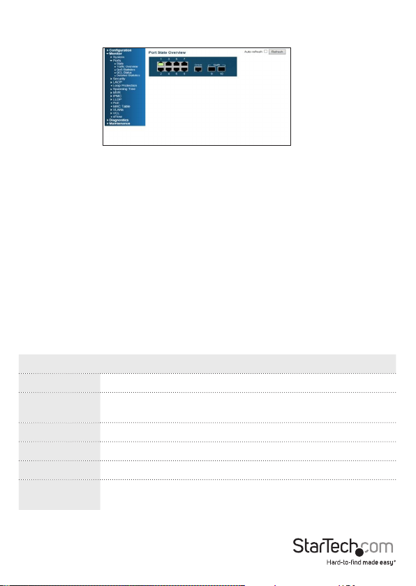
When you log in to the Web management UI, the default screen that you see is the Port
State Overview screen:
Ports 1 to 8 are Gigabit Ethernet ports, and ports 9 and 10 are the SFP slots. When the
port image is green, it means that the port is connected.
By default, Auto-refresh mode is turned o. When Auto-refresh mode is turned on, the
state of the ports is automatically refreshed every 5 seconds. To turn on Auto-refresh
mode, select the Auto-refresh check box. To manually update the state of the ports,
click Refresh.
To view detailed statistics about any of the ports, click the corresponding image of the
port.
There is a menu located on the left side of the main Web management screen that
includes numerous menu options organized under four categories: Conguration,
Monitor, Diagnostic, and Maintenance.
About the menu options in the Conguration drop-down list
To access the menu options, on the left side of the main screen of the Web
management UI, click Conguration > System > <menu option>.
Menu option Description
Information Specify the system contact, name, location, and time zone oset.
IP Congure the IPv4 (static IP address and DHCP client), and the
VLAN ID settings.
IPv6 Congure the IPv6 (static IP address and DHCP client) settings.
NTP Congure the NTP server setting (maximum: 5).
Time Set the time zone and daylight saving time.
Log Congure the Remote System Log Server, including the 3 levels:
Info, Warning, and Error.
Instruction Manual
8
Page 17

To access the menu options, on the left side of the main screen of the Web
management UI, click Conguration > Power Reduction > <menu option>.
Menu option Description
LED Reduce the LED intensity during specied hours, and
congure the link change at error settings.
EEE (Energy Ecient
Ethernet)
Turn on and turn o EEE, and congure the EEE urgent
queues.
To access the menu options, on the left side of the main screen of the Web
management UI, click Conguration > <menu option>.
Menu option Description
Ports Congure the connection settings of the ports.
Loop Protection Set the ports to shut down if the ports are stuck in a loop.
MVR Congure the Multicast VLANs Registration.
MAC Table Congure the aging time, dynamic learning, and static
addresses.
Mirroring Specify the source and destination port for mirroring.
UPnP Turn on and turn o the UPnP, and congure the TTL and AD
settings.
sFlow Turn on sFlow and congure the ow and counter samplers
for each port.
To access the menu options, on the left side of the main screen of the Web
management UI, click Conguration > Security > Switch <menu option>.
Menu option Description
Users Create user accounts and passwords, and set privilege levels.
Aud Method Congure the authentication method for console and web
access using the local database and RADIUS.
SSH Turn on and turn o SSH.
Instruction Manual
9
Page 18

HTTPS Turn on and turn o HTTPS and specify the auto-redirect
setting.
Access Management Turn on and turn o Access Management, set the IP address
range for HTTP and HTTPS, and specify the SNMP and
TELNET/SSH access.
To access the menu options, on the left side of the main screen of the Web
management UI, click Conguration > Security > Switch > SNMP > <menu option>.
Menu option Description
System Congure SNMP, version (v1, v2c, and v3), read and write
community, and Trap.
Communities Specify the community for SNMPv3 and the source IP
address.
Users Congure the SNMPv3 user.
Groups Congure the SNMP group.
Views Congure the View Name and type.
Access Congure the access authority.
To access the menu options, on the left side of the main screen of the Web
management UI, click Conguration > Security > Switch > RMON > <menu option>.
Menu option Description
Statistics Congure the RMON statistics table.
History Congure the RMON history table.
Alarm Congure the RMON alarm table.
Event Congure the RMON event table.
Instruction Manual
10
Page 19

To access the menu options, on the left side of the main screen of the Web
management UI, click Conguration > Security > Network > <menu option>.
Menu option Description
Limit Control Limit the numer of users on a specic port.
NAS Congure the Network Access Server.
To access the menu options, on the left side of the main screen of the Web
management UI, click Conguration > Security > Network > ACL > <menu option>.
Menu option Description
Ports Specify the ACL parameters of each switch port.
Rate Limiters Specify the rate limiters for the switch ACL.
Access Control List View the Access Control List.
To access the menu options, on the left side of the main screen of the Web
management UI, click Conguration > Security > Network > DHCP > <menu option>.
Menu option Description
Snooping Turn on and turn o DHCP snooping.
Relay Turn on and turn o DHCP relay and set up the relay server.
To access the menu options, on the left side of the main screen of the Web
management UI, click Conguration > Security > Network > IP Source Guard >
<menu option>.
Menu option Description
Conguration Turn on and turn o the IP Source guard and set up the
maximum number of dynamic clients for each port.
Static Table Manually insert the IP Source guard table.
Instruction Manual
11
Page 20

To access the menu options, on the left side of the main screen of the Web
management UI, click Conguration > Security > Network > ARP Inspection >
<menu option>.
Menu option Description
Conguration Turn on and turn o the Global ARP inspection.
Static Table Manually insert the ARP Inspection table.
To access the menu option, on the left side of the main screen of the Web
management UI, click Conguration > Security > AAA.
Menu option Description
AAA Congure the Authentication Servers.
To access the menu options, on the left side of the main screen of the Web
management UI, click Conguration > Aggregation > <menu option>.
Menu option Description
Static Congure the aggregation mode and group.
LACP View the current LACP port congurations and if neccesary,
change them.
To access the menu options, on the left side of the main screen of the Web
management UI, click Conguration > Spanning Tree > <menu option>.
Menu option Description
Bridge Settings Congure the global bridge setting for STP and RSTP, and
congure the edge port setting for BPDU ltering, BPDU
guard, and port error recovery.
MSTI Mapping Map VLANs to a specic MSTP instance.
MSTI Priorities Specify the priority for each MSTI.
VLAN Membership Congure the VLAN groups.
Instruction Manual
12
Page 21

Ports Specify the default PVID and VLAN attributes.
CIST Ports Congure the interface settings for STA.
MSTI Ports Congure the interface settings for an MST instance.
To access the menu options, on the left side of the main screen of the Web
management UI, click Conguration > IPMC > IGMP Snooping > <menu option>.
Menu option Description
Basic conguration Congure the global and port settings for multicast ltering.
VLAN Conguration Congure the IGMP Snooping for each VLAN interface.
Port Group Filtering Congure ports to a specic ltering group.
To access the menu options, on the left side of the main screen of the Web
management UI, click Conguration > IPMC > MLD Snooping > <menu option>.
Menu option Description
Basic conguration Congure the global and port settings for multicast ltering.
VLAN Conguration Congure the IGMP Snooping for each VLAN interface.
Port Group Filtering Congure ports to a specic ltering group.
To access the menu options, on the left side of the main screen of the Web
management UI, click Conguration > LLDP > <menu option>.
Menu option Description
LLDP Congure the global parameters and the optional TLVs for
a port.
LLDP-MED Congure the LLDP-MED attributes.
Instruction Manual
13
Page 22

To access the menu options, on the left side of the main screen of the Web
management UI, click Conguration > VLANs > <menu option>.
Menu option Description
VLAN Memberships Specify the VLAN groups.
Ports Congure the VLAN setting for each port.
To access the menu options, on the left side of the main screen of the Web
management UI, click Conguration > Private VLANs > <menu option>.
Menu option Description
PVLAN Membership Specify the PVLAN groups.
Port isolation Congure the port isolation.
To access the menu option, on the left side of the main screen of the Web
management UI, click Conguration > VCL > <menu option>.
Menu option Description
MAC-based VLANs Map a specic source MAC Address to a VLAN.
IP Subnet-based
Assign a subnet IP to a specic VLAN.
VLAN
To access the menu options, on the left side of the main screen of the Web
management UI, click Conguration > VCL > Protocol-based VLAN > <menu
option>.
Menu option Description
Protocol to Group Create a specic protocol group.
Group to VLAN Map a specic protocol group to a VLAN.
Instruction Manual
14
Page 23

To access the menu options, on the left side of the main screen of the Web
management UI, click Conguration > Voice VCL > <menu option>.
Menu option Description
Conguration Congure the global settings, allow or block Voice VLAN by
port setting.
OUI Congure the Voice VLAN and OUI mapping table.
To access the menu options, on the left side of the main screen of the Web
management UI, click Conguration > QoS > <menu option>.
Menu option Description
Port Classication Congure the QoS Ingress Classication settings for all ports.
Port Policing Congure the QoS Ingress Port policers to limit trac ows
by a specic rate.
Port Scheduler See an overview of the egress priority status for each port,
and set the egress queue mode and sharper.
Port Shaping See an overview of the egress sharper for each port, and set
the egress queue mode and sharper.
Port Tag Remarking See an overview of the egress tag remarking, and set the tag
remarking mode.
Port DSCP Congure the egress translation and classication, and set
the egress DSCP rewrite value.
DSCP-Based QoS Congure the Ingress classication setting for DSCP-based
QoS.
DSCP Translation Set the translation of Ingress classication and the egress
DP Iv.
DSCP Classication Map the DSCP value to the QoS class and DP level.
QoS Control List Congure the QoS Control Entry based on parameters such
as VLAN ID, UDP/TCP port, IPv4 DSCP, or tag priority.
Storm Control Set the limitation for broadcast, unicast, and multicast trac.
Instruction Manual
15
Page 24

About the menu options in the Monitor drop-down list
To access the menu options, on the left side of the main screen of the Web
management UI, click Monitor > System > <menu option>.
Menu option Description
Information View the system contact, name, location, system time, rmware
version, and the MAC address for the switch.
CPU load View the CPU load by realtime SVG graph.
Log View logged messages with the selected level (Info, Warning,
Error, and All).
Detailed Log View the fully logged message.
To access the menu options, on the left side of the main screen of the Web
management UI, click Monitor > Ports > <menu option>.
Menu option Description
State View a graphic image of the front panel of the switch to see the
current port states.
Trac Overview View the basic port statistics.
QoS Statistics View the total of incoming and outgoing egress queues.
QCL Status View the status of the QoS Control Lists.
Detailed Statistics View the detailed port statistics.
To access the menu option, on the left side of the main screen of the Web
management UI, click Monitor > Security > <menu option>.
Menu option Description
Access Management
Statistics
View the incoming management packets, including HTTP,
HTTPS, SNMP, TELNET, and SSH.
Instruction Manual
16
Page 25

To access the menu options, on the left side of the main screen of the Web
management UI, click Monitor > Security > Network > Port Security > <menu
option>.
Menu option Description
Switch View the module legend and the status of each port, including the
MAC address learning and the maximum allowed MAC count.
Port View the MAC address, VLAN ID, state, time of addition, and the age
and hold of the timer for each port.
To access the menu options, on the left side of the main screen of the Web
management UI, click Monitor > Security > Network > NAS > <menu option>.
Menu option Description
Switch View the authentication service status and information for
each port.
Port View the authentication statistics, port status, and
authentication method.
To access the menu options, on the left side of the main screen of the Web
management UI, click Monitor > Security > Network > <menu option>.
Menu option Description
ACL Status View the ACL status by dierent ACL users.
ARP Inspection View the dynamic ARP inspection table, sorted by port
number, VLAN ID, MAC address, and IP address.
IP Source Guard View the IP Source Guard table, sorted by port number,
VLAN ID, and IP address.
To access the menu options, on the left side of the main screen of the Web
management UI, click Monitor > Security > Network > DHCP > <menu option>.
Menu option Description
Snooping Statistics View the statistics for each packet type.
Relay Statistics View the DHCP relay statistics.
Instruction Manual
17
Page 26

To access the menu options, on the left side of the main screen of the Web
management UI, click Monitor > Security > AAA > <menu option>.
Menu option Description
RADIUS Overview View the status of the associated authentication RADIUS
servers.
RADIUS Details View the trac and status of each of the associated
RADIUS servers.
To access the menu options, on the left side of the main screen of the Web
management UI, click Monitor > Security > Switch > RMON > <menu option>.
Menu option Description
Statistics View an overview of the RMON Statistics entries.
History View an overview of the RMON History entries.
Alarm View an overview of the RMON Alarm entries.
Event View an overview of the RMON Event table entries.
To access the menu options, on the left side of the main screen of the Web
management UI, click Monitor > LACP > <menu option>.
Menu option Description
System Status View the LACP information for each local port, including
the Aggr ID, Partner system ID, and Partner key.
Port Status View the key, Aggr ID, Partner system ID, and Partner port
for each local port.
Port Statistics View the statistics for LACP protocol messages.
Instruction Manual
18
Page 27

To access the menu options, on the left side of the main screen of the Web
management UI, click Monitor > <menu option>.
Menu option Description
Loop Protection View the loop status for each port.
MAC Table View the Dynamic and Static MAC address table.
sFlow View the receiver and per-port sFlow statistics.
To access the menu options, on the left side of the main screen of the Web
management UI, click Monitor > Spanning Tree > <menu option>.
Menu option Description
Bridge Status View the STP detailed bridge status, CIST Ports, and
Aggregations state.
Port Status View the CIST role, State, and uptime for each port.
Port Statistics View the statistics for the RSTP, STP, and TCN packets.
To access the menu options, on the left side of the main screen of the Web
management UI, click Monitor > MVR > <menu option>.
Menu option Description
Statistics View the IGMP/MLD statistics used by the MVR.
MVR Channel Groups View the MVR channel information, including the VLAN ID
groups and port members.
MVR SFM Information View the Source-Filtered Multicast information, including
the Source-Specic Multicast information.
Instruction Manual
19
Page 28

To access the menu options, on the left side of the main screen of the Web
management UI, click Monitor > IPMC > IGMP Snooping > <menu option>.
Menu option Description
Status View the statistics related to IGMP packets passed
upstream to the IGMP Querier or downstream to multicast
clients.
Groups Information View information about the IGMP snooping groups.
IPv4 SFM Information View information about the IGMP Source-Filtered
Multicast, including Source-Specic Multicast.
To access the menu options, on the left side of the main screen of the Web
management UI, click Monitor > IPMC > MLD Snooping > <menu option>.
Menu option Description
Status View the MLD snooping status and statistics.
Groups Information View the MLD group table, which is sorted by VLAN ID and
then by group.
IPv6 SFM Information View the MLD Source-Filtered Multicast information table,
including the Source-Specic Multicast information.
To access the menu options, on the left side of the main screen of the Web
management UI, click Monitor > LLDP > <menu option>.
Menu option Description
Neighbours View the LLDP information for the remote device that is
connected to a port on the switch.
LLDP-MED Neighbours View the information for the remote device that is
advertising LLDP-MED.
EEE View an overview of the EEE information exchanged by
LLDP.
Port Statistics See an overview of all of the LLDP trac.
Instruction Manual
20
Page 29

To access the menu options, on the left side of the main screen of the Web
management UI, click Monitor > VLANs > <menu option>.
Menu option Description
VLAN Membership View the port members for a specic VLAN ID.
VLAN Port View the VLAN Port Status for a Static user.
To access the menu options, on the left side of the main screen of the Web
management UI, click Monitor > VCL > <menu option>.
Menu option Description
MAC-based VLAN View the MAC-based VLAN entries congured by various
MAC-based VLAN users.
About the menu options in the Diagnostics drop-down list
To access the menu options, on the left side of the main screen of the Web
management UI, click Diagnostics > <menu option>.
Menu option Description
Ping Test a specic IP address by using the ping function.
Ping6 Test a specic IPv6 address by using the ping function.
About the menu options in the Maintenance drop-down list
To access the menu options, on the left side of the main screen of the Web
management UI, click Maintenance > <menu option>.
Menu option Description
Restart Device Restart the switch.
Factory Defaults Restore all of the settings to the factory default settings.
Instruction Manual
21
Page 30

About the menu options in the Maintenance drop-down list
To access the menu options, on the left side of the main screen of the Web
management UI, click Maintenance > Software > <menu option>.
Menu option Description
Upload Use the Web UI to update the rmware for the switch.
Image Select Select a recovery rmware to use to start the switch.
About the menu options in the Maintenance drop-down list
To access the menu options, on the left side of the main screen of the Web
management UI, click Maintenance > Conguration > <menu option>.
Menu option Description
Save Save the conguration to your local PC.
Upload Restore the previous conguration from a le.
Instruction Manual
22
Page 31

Changing the Conguration settings
Change the System Information settings
1. On the main screen of the Web management UI, click Conguration > System >
Information.
2. Do any of the following:
• To specify an administrator for the switch, in the System Contact eld, enter a
name (maximum length is 255 characters).
• To specify a name for the switch, in the System Name eld, enter a name
(maximum length is 255 characters).
• To specify the location that the switch is in, in the System Location eld, enter a
location (maximum length is 255 characters).
Change the System IP settings
The following table describes the System IP settings that you can change:
Option Description
DHCP Client Enable the DHCP client or disable the DHCP client and use a static
IP Address Sets the static IP address of the switch, if not acting as a DHCP
IP Mask The mask used to determine which subnet the switch belongs to.
IP Router The IP address of the gateway.
VLAN ID The VLAN that the switch is associated with. The VLAN ID needs to
DNS Server A domain name server that resolves client host name to IP address
DNS Proxy Enable this feature to maintain a DNS database.
Renew Use to renew a DHCP lease.
IP address.
client. The default IP is 192.168.2.1.
match your management’s PC/NB VLAN ID. The range is between 1
and 4096 and the default VLAN ID is 1.
requests.
Instruction Manual
23
Page 32

To congure the static IP address and enable the DHCP client, do the following:
1. On the main screen of the Web management UI, click Conguration > System > IP.
2. Do one of the following:
• To enable the DHCP client, select the DHCP check box.
• To disable the DHCP client and use a static IP address, clear the DHCP check box.
3. In the Congured column, complete the IP Address, IP Mask, IP Router, and SNTP
Server IP elds.
4. To renew the IP Address, click Renew.
5. To maintain a local DNS database, select the DNS Proxy check box.
6. To apply the changes that you made, click Save.
To restore the previous settings, click Restore.
Change the System IPv6 settings
The following table describes the System IPv6 settings that you can change:
Option Description
Auto Conguration Enable the DHCP client, or disable the DHCP client and use a
Address The IPv6 address must adhere to the IPv6 Addressing
Prex Specify the IPv6 prex for your switch. The allowed range is
Router Specify the IPv6 gateway for your switch.
static IP address.
Architecture format. The IPv6 address is in 128-bit records
represented as 8 elds of up to 4 hexadecimal digits with a
colon separating each eld.
between 1 and 128.
1. On the main screen of the Web management UI, click Conguration > System >
IPv6.
2. Do one of the following:
• To enable Auto Conguration, select the Auto Conguration check box.
• To disable Auto Conguration, clear the Auto Conguration check box.
3. In the Congured column, complete the Address eld.
Instruction Manual
24
Page 33

4. If necessary, complete the Router eld.
5. To renew the IPv6 Address, click Renew.
6. To apply the changes that you made, click Save.
To restore the previous settings, click Restore.
Change the NTP Conguration settings
The following table describes the NTP Conguration settings that you can change:
Option Description
Mode Enable or disable NTP Client mode.
Server 1 to 5 Specify the IPv4 or IPv6 of up to 5 NTP servers.
1. On the main screen of the Web management UI, click Conguration > System >
NTP.
2. Do one of the following:
• To enable NTP Client mode, in the Mode drop-down list, click Enabled.
• To disable NTP Client mode, in the Mode drop-down list, click Disabled.
3. In the Server elds, enter the IP address of the NTP Server.
4. To save your changes, click Save.
To restore the previous settings, click Reset.
Change the Time settings
The following table describes the Time settings that you can change:
Option Description
Time Zone Select a time zone from a list of world-wide time zones.
Acronym Enter an acronym for the time zone that you selected. You
Daylight Saving Time Set the daylight saving time to recur every year or to just
Month Specify the month to start and end daylight saving time.
can use up to 16 alphanumeric characters and the acronym
can contain “-”, “_”, and “.”.
occur once.
Instruction Manual
25
Page 34

Date Specify the day to start and end daylight saving time.
Year Specify the year to start and end daylight saving time.
Hours Specify the hour to start and end daylight saving time.
Minutes Specify the minute to start and end daylight saving time.
Oset Specify the number of minutes to add during daylight
saving time. The range is between 1 and 1440 minutes.
To congure the time settings, do the following:
1. On the main screen of the Web management UI, click Conguration > System >
Time.
2. In the Time Zone drop-down list, click a time zone.
3. In the Acronym eld, enter an acronym to describe the time zone that you selected.
4. To enable daylight saving time, in the Daylight Saving Time drop-down list, click
Enabled.
5. Do one of the following:
• To set the daylight saving time to repeat every year, in the Daylight Saving Time
drop-down list, click Recurring.
• To set the daylight saving time to only occur once, click Non-Recurring.
6. To congure the date to start daylight saving time, do the following:
• In the Month drop-down list, click a month.
• In the Date drop-down list, click a day of the month.
• In the Year drop-down list, click a year.
• In the Hours drop-down list, click an hour.
• In the Minutes drop-down list, click a numeric value.
7. To congure the date to end daylight saving time, repeat step 6.
8. To enter the number of minutes to add during daylight saving time, in the Oset
eld, enter a numeric value.
9. To save your changes, click Save.
To restore the previous settings, click Reset.
Instruction Manual
26
Page 35

Change the Log settings
The following table describes the Log settings that you can change:
Option Description
Server Mode Enable or disable remote system logging.
Server Address Specify the IP address of the server used for remote system
Syslog Level Select one of the following logging event levels: Info, Warning,
1. On the main screen of the Web management UI, click Conguration > System >
Log.
2. Do one of the following:
• To enable Server mode, in the Server Mode drop-down list, click Enabled.
• To disable Server mode, in the Server Mode drop-down list, click Disabled.
3. In the Server Address eld, enter the IP address of the server.
4. Do one of the following:
• To send info, warnings, and errors, in the Syslog Level drop-down list, click Info.
• To send warnings and errors, in the Syslog Level drop-down list, click Warning.
• To send errors, in the Syslog Level drop-down list, click Error.
5. To save your changes, click Save.
To restore the previous settings, click Reset.
logging.
or Error.
Change the LED settings
The following table describes the LED settings that you can change to reduce the LED
intensity during specied hours to save power.
Option Description
Time Specify the length of time to change the LED itensity for.
Intensity Set the LED intensity percentage level. There are 10 levels of
Instruction Manual
LED intensity, increasing by 10% intensity with each level. 0%
intensity level means the LED is turned o and 100% intensity
means the LED is at full power.
27
Page 36

On time at link
change
On at errors Set the LED to operate at full power when an error occurs.
1. On the main screen of the Web management UI, click Conguration > Power
Reduction > LED.
2. In the Time drop-down list, click a time.
3. In the Intensity drop-down list, click a percentage value.
4. To add the LED rule to the switch, click Add.
5. To set the duration of time that the LED operates at full power when a link change
occurs, in the Sec. eld, enter a numeric value.
6. To set the LED to operate at full power when an error occurs, select the On at errors
check box.
7. To save your changes, click Save.
To restore the previous settings, click Reset.
Set the duration of time that the LED operates at full power
when a link change occurs.
Change the EEE settings
The following table describes the EEE (Energy Ecient Ethernet) settings that you can
change:
Option Description
Enable Enable or disable EEE for each port.
EEE Urgent Queue Set queues to activate the transmission of frames as soon as
Note: If a port is greyed out on the EEE Conguration screen, it means that the port
isn’t EEE capable and can’t be set.
1. On the main screen of the Web management UI, click Conguration > Power
Reduction > EEE.
2. To enable EEE for a port, select the Enabled check box next to the port that you
want to enable.
3. If necessary, select the EEE Urgent Queues check box next to a port.
4. To save your changes, click Save.
To restore the previous settings, click Reset.
Instruction Manual
any data is available. If not set, the queue will postpone the
transmission until 3 000 bytes are ready to be transmitted.
28
Page 37

Change the Port settings
On the Port Conguration screen, you can specify the parameters for each port,
including enabling and disabling ports, setting port speeds such as auto, half-duplex,
full-duplex, and more. You can also set the frame size, specify the collision policy and
power control. See the table below for more information about the settings that you
can change.
Option Description
Link View the status of each port.
Speed View the current speed in the Current column. Choose
Flow Control View the ow control state of Rx and Tx in the Current
Maximum Frame Size Specify the maximum frame size allowance to transfer for
Excessive Collision
Mode
Power Control Set the options for automatic power saving mode.
1. On the main screen of the Web management UI, click Conguration > Ports.
2. Do one of the following:
• To disable the port interface, in the Congured drop-down list, click Disabled.
• To enable auto-negotiation, in the Congured drop-down list, click Auto.
• To set the switch to support 10 Mbps half-duplex, in the Congured drop-down
list, click 10Mbps HDX.
• To set the switch to support 10 Mbps full-duplex, in the Congured drop-down
list, click 10Mbps FDX.
• To set the switch to support 100 Mbps half-duplex, in the Congured dropdown list, click 100Mbps HDX.
• To set the switch to support 100 Mbps full-duplex, in the Congured drop-down
list, click 100Mbps FDX.
• To set the switch to support 1 Gbps full-duplex, in the Congured drop-down
list, click 1Gbps FDX.
between seven options in the Congured column.
columns. You can also enable Flow Control to eliminate
packet loss.
each port.
Congure the behavior for port transmit collisions.
Instruction Manual
29
Page 38

3. To enable ow control, select the Congured check box.
4. To specify the maximum frame size allowance to transfer for each port, in the
Maximum Frame Size eld, enter a numeric value.
5. To change the settings for the excessive collision mode, in the Excessive Collision
Mode drop-down list, click an option.
6. To change the options for the automatic power saving mode, do one of the
following:
• To set the switch to detect unused Ethernet ports on network devices and power
them down, in the Power Control drop-down list, click ActiPHY.
• To use an intelligent algorithm that actively adjusts the power level needed
based on cable length, in the Power Control drop-down list, click PerfectReach.
• To enable both ActiPHY and PerfectRead, in the Power Control drop-down list,
click Enabled.
• To disable the power saving mode, in the Power Control drop-down list, click
Disabled.
7. To save your changes, click Save.
8. To manually reload the information on the screen, click Refresh.
To restore the previous settings, click Reset.
Change the User settings
On the User Conguration screen, you can congure the user name and password
authority for dierent privilege levels. See the table below for more information about
the settings that you can change.
Option Description
User Name Enter a user name that is up to 31 characters long (letters,
Password Enter a password that is up to 31 characters long for a
Privilege Level Set a privilege level for a user between the range of 1 and
numbers, and underscores are allowed).
user.
15.
1. On the main screen of the Web management UI, click Conguration > Security >
Switch > Users.
2. Complete the User Name, Password, and Password (again) elds.
Instruction Manual
30
Page 39

3. In the Privilege Level drop-down list, click a level option.
4. To save your changes, click Save.
5. To cancel your changes, click Cancel.
To restore the previous settings, click Reset.
Change the Privilege Levels settings
On the Privilege Levels screen, you can set the privilege level required to read
or congure a software module or system setting. See the table below for more
information about the settings that you can change.
Option Description
Group Name The name used to identify the privilege group.
Privilege Level Set a privilege level for a user between the range of 1 and
1. On the main screen of the Web management UI, click Conguration > Security >
Switch > Privilege Levels.
2. Do any of the following:
• For any of the group names, in the Conguration Read-only drop-down list,
click a privilege level.
• For any of the group names, in the Conguration/Execute Read/Write drop-
down list, click a privilege level.
• For any of the group names, in the Status/Statistics Read-only drop-down list,
click a privilege level.
• For any of the group names, in the Status/Statistics Read/Write drop-down list,
click a privilege level.
3. To save your changes, click Save.
To restore the previous settings, click Reset.
15.
Change the Authentication Method settings
On the Authentication Method Conguration screen, you can specify the
authentication method for access management using console, telnet, ssh, and Web.
Access can be controlled by local (password) or remote access authentication (RADIUS
server). See the table below for more information about the settings that you can
change.
Instruction Manual
31
Page 40

Option Description
Client Specify the authentication method for the administrator.
Authentication Method Select 1 of 4 authentication methods.
Fallback Set the switch to check by local password if fallback is
1. On the main screen of the Web management UI, click Conguration > Security >
Switch > Auth Methods.
2. For any of the client types, do the following:
• To disable access via specied management interface, in the Authentication
Method drop-down list, click None.
• To check by password, in the Authentication Method drop-down list, click
Local.
• To authenticate using the RADIUS server, in the Authentication Method dropdown list, click RADIUS.
• To authenticate using the TACACS+ server, in the Authentication Method dropdown list, click TACACS+.
3. If necessary, select the Fallback check box for any of the client types.
4. To save your changes, click Save.
To restore the previous settings, click Reset.
checked when radius server authentication fails.
Set up the Secure Shell management interface
On the SSH Conguration screen, you can enable SSH. SSH service on this switch only
supports password authentication. It can be authenticated by RADIUS, TACACS+, or
locally.
1. On the main screen of the Web management UI, click Conguration > Security >
Switch > SSH.
2. Do one of the following:
• To enable SSH, in the Mode drop-down list, click Enabled.
• To disable SSH, in the Mode drop-down list, click Disabled.
3. To save your changes, click Save.
To restore the previous settings, click Reset.
Instruction Manual
32
Page 41

Enable HTTPS
On the HTTPS Conguration screen, you can enable or disable HTTPS and Automatic
Redirect mode. When Automatic Redirect mode is enabled, the Web browser is
automatically redirected to an HTTPS connection when both HTTPS and Automatic
Redirect modes are enabled.
1. On the main screen of the Web management UI, click Conguration > Security >
Switch > HTTPS.
2. Do one of the following:
• To enable HTTPS, in the Mode drop-down list, click Enabled.
• To disable HTTPS, in the Mode drop-down list, click Disabled.
3. If HTTPS is enabled, do one of the following:
• To enable Automatic Redirect, in the Mode drop-down list, click Enabled.
• To disable Automatic Redirect, in the Mode drop-down list, click Disabled.
4. To save your changes, click Save.
To restore the previous settings, click Reset.
Congure the access management settings
On the Access Management Conguration screen, you can create a list of up to 16
IP addresses or IP address groups that allow access management through the HTTP/
HTTPS/SNMP/TELNET/SSH.
1. On the main screen of the Web management UI, click Conguration > Security >
Switch > Access Management.
2. Do one of the following:
• To enable access management, in the Mode drop-down list, click Enabled.
• To disable access management, in the Mode drop-down list, click Disabled.
3. If access management is enabled, click Add New Entry.
4. Set up a list of rules for HTTP/HTTPS, SNMP, TELNET/SSH.
5. To save your changes, click Save.
To restore the previous settings, click Reset.
Instruction Manual
33
Page 42

Congure the SNMP settings
On the SNMP System Conguration screen, you can congure the SNMP settings,
including community name, trap host, public traps, and so on. See the table below for
more information about the settings that you can change.
Option Description
Mode Enable or disable the SNMP service.
Version Specify the SNMP version (SNMP v1, SNMP v2c, or SNMP
Read Community Specify the community that has read access.
Write Community Specify the community that has read/write access.
Engine ID View the SNMP v3 engine ID (only available for SNMP v3).
Trap Mode Enable or disable the SNMP traps.
Trap Version Specify the trap version (SNMP v1, SNMP v2c, or SNMP v3).
Trap Community Specify the community string for SNMP trap packets.
Trap Destination
Address
Trap Authentication
Failure
Trap Link-up and Linkdown
Trap Inform Mode Enable trap inform mode to send a notication as
Trap Inform Timeout Set the length of time in seconds to wait for ACK.
Trap Inform Retry
Times
Trap Probe Security
Engine ID
v3).
Specify the IP address of the server to receive trap packets.
Enable trap authentication failure to issue a notication
message to the trap destination address whenever a
SNMP request fails.
Enable trap link-up and link-down to issue a notication
message to the trap destination address whenever a port
link is established or broken.
an inform message (only available for SNMP v2c and
SNMP v3). This mode can guarantee that the message is
received.
Set the maximum number of retry times before timeout.
Specify whether or not to use the engine ID of the SNMP
trap probe in trap and inform messages (only available for
SNMP v3).
Instruction Manual
34
Page 43

Trap Security Engine ID View the SNMP trap security engine ID (only available for
Trap Security Name View the trap security name (only available for SNMP v3).
1. On the main screen of the Web management UI, click Conguration > Security >
Switch > SNMP > System.
2. To enable SNMP mode, in the Mode drop-down list, click Enabled.
3. In the Version drop-down list, click a version.
4. If required, in the Read Community and Write Community elds, change the
community access.
5. To enable the switch to send SNMP traps, in the Trap Mode drop-down list, click
Enabled.
6. In the Trap Version drop-down list, click a version.
7. Complete the Trap Community, Trap Destination Address, and Trap Destination
IPv6 Address elds.
8. To enable the switch to send a notication message to trap destination address
when an SNMP request fails, in the Trap Authentication Failure drop-down list,
click Enabled.
9. To enable the switch to send a notication message to trap destination address
when a port link is established or broken, in the Trap Link-up and Link-down dropdown list, click Enabled.
10. To enable the switch to send a notication as an inform message, in the Trap
Inform Mode drop-down list, click Enabled.
11. Complete the Trap Inform Timeout (seconds) and Trap Inform Retry Times elds.
12. To save your changes, click Save.
To restore the previous settings, click Reset.
SNMP v3).
Change the SNMPv3 community conguration settings
The table below describes the settings that you can change on the SNMPv3
Community Conguration screen.
Option Description
Community Specify the community string to allow access to the SNMP
Instruction Manual
agent (range is between 1 and 32).
35
Page 44

Source IP Specify the IP address of the SNMP client.
Source Mask Specify the subnet mask of the SNMP client.
1. On the main screen of the Web management UI, click Conguration > Security >
Switch > SNMP > Communities.
2. Do any of the following:
• Complete the Source IP and Source Mask elds.
• To delete a community, select the Delete check box next to the community that
you want to remove.
• To add a new community string, click Add New Entry and complete the
instructions on the screen.
3. To save your changes, click Save.
To restore the previous settings, click Reset.
Change the SNMPv3 User settings
On the SNMPv3 User Conguration screen, you can specify an engine ID, user name,
and security level, as well as set the authentication and privacy level for each SNMPv3
user. See the table below for more information about the settings that you can change.
Option Description
Engine ID View the engine identier for the SNMP agent (only
User Name Specify a unique user name (between 1 and 32
Security Level Set 1 of 3 security levels:
Authentication Protocol Set the method for authentication (None, MD5, or SHA).
Authentication Password Set a password between 1 and 32 text characters long.
available for SNMPv3).
characters long) for the SNMP.
• NoAuth, NoPriv (no authentication and encryption
applied during the communication).
• Auth, NoPriv (the communication has authentication
applied to it, but not encryption).
• Auth, Priv (both authentication and encryption are
applied during the communication).
Instruction Manual
36
Page 45

Privacy Protocol Set the encryption algorithm (none or 56-bit DES).
Privacy Password Set a privacy passphrase between 8 and 40 characters
1. On the main screen of the Web management UI, click Conguration > Security >
Switch > SNMP > Users.
2. Click Add New User.
3. In the Engine ID eld, enter a remote engine ID.
4. Complete the User Name, Security Level, Authentication Password, Privacy
Protocol, and Privacy Password elds.
5. To save your changes, click Save.
6. To delete a user conguration, in the Delete column, select the check box next to
the entry that you want to remove.
To restore the previous settings, click Reset.
long).
Change the SNMPv3 Group settings
On the SNMPv3 Group Conguration screen, you can dene a specic SNMPv3 group
and restrict the access policy to read and write views. See the table below for more
information about the settings that you can change.
Option Description
Security Model Select 1 of 3 user security models: v1, v2, and USM
Security Name Set a security name between 1 and 32 characters in
Group Name Enter a name for the SNMP group.
1. On the main screen of the Web management UI, click Conguration > Security >
Switch > SNMP > Groups.
2. To create a new group, click Add New Entry.
3. In the Security Model column, select a model type.
4. In the Security Name column, select a name.
5. In the Group Name eld, enter a name for the group.
6. To save your changes, click Save.
To restore the previous settings, click Reset.
Instruction Manual
(User-based Security Model).
length that is used to connect to the SNMP agent.
37
Page 46

Change the SNMPv3 View settings
On the SNMPv3 View Conguration screen, you can dene the restricts access policy
for a specic MIB tree. The default_view includes access ability for the whole MIB tree.
See the table below for more information about the settings that you can change.
Option Description
View Name Specify a name between 1 and 32 characters long for the SNMP
View Type Set whether the OID is included or excluded for a specic SNMP
OID Subtree Specify the object identiers of branches within the MIB tree.
1. On the main screen of the Web management UI, click Conguration > Security >
Switch > SNMP > Views.
2. To create a new view, click Add New Entry.
3. In the View Name column, enter a name for the SNMP view.
4. In the View Type drop-down list, click a view type.
5. In the OID Subtree column, enter an identier of the OID subtree.
6. To save your changes, click Save.
To restore the previous settings, click Reset.
view.
view.
Change the SNMPv3 Access settings
On the SNMPv3 Access Conguration screen, you can dene the access rights for a
portion of the MIB tree. See the table below for more information about the settings
that you can change.
Option Description
Group Name Specify a name between 1 and 32 characters long for the SNMP
Security Model Select 1 of 3 user security models: v1, v2, and USM (User-based
group.
Security Model).
Instruction Manual
38
Page 47

Security Level Set 1 of 3 security levels:
• NoAuth, NoPriv (no authentication and encryption applied
during the communication).
• Auth, NoPriv (the communication has authentication applied
to it, but not encryption).
• Auth, Priv (both authentication and encryption are applied
during the communication).
Read View Name Select a view name for read access.
Write View Name Select a view name for write access.
Note: You can have more than one access policy for an SNMPv3 group.
1. On the main screen of the Web management UI, click Conguration > Security >
Switch > SNMP > Access.
2. To create a new access prole, click Add New Entry.
3. In the Group Name column, enter a name for the SNMP group.
4. In the Security Model column, select a security model type.
5. In the Security Level column, select a security level type.
6. In the Read View Name drop-down list, click a view name.
7. In the Write View Name drop-down list, click a view name.
8. To save your changes, click Save.
9. To delete an access conguration, in the Delete column, select the check box next
to the conguration that you want to remove.
To restore the previous settings, click Reset.
Change the RMON Statistics settings
On the RMON Statistics Conguration screen, you can congure the page to set the
ID for MIBs and to store real-time LAN statistics, including utilization, collisions, and
CRC errors. See the table below for more information about the settings that you can
change.
Option Description
Delete Delete the entry of MIBs.
ID Congure the index for the statistics. The index range is
Data Source View the port ID that you want to monitor. The number
Instruction Manual
between 1 and 65535.
corresponds to the port number.
39
Page 48

1. On the main screen of the Web management UI, click Conguration > Security >
Switch > RMON > Statistics.
2. To create a new MIBs, click Add New Entry.
3. In the ID eld, enter an ID number.
4. In the Data Source eld, enter a port number.
5. To delete the MIBs entry, click Delete next to the MIBs that you want to delete.
6. To save your changes, click Save.
To restore the previous settings, click Reset.
Change the RMON History settings
On the RMON History Conguration screen, you can see an overview of the history of
selected LAN statistics, including utilization, collisions, and CRC errors. See the table
below for more information about the settings that you can change.
Option Description
Delete Delete the History conguration entry.
ID Congure the index for the group of statistics. The index range
Data Source View the port ID that you want to monitor. The number
Interval Specify the interval in seconds for sampling the History
Buckets The maximum number of entries to collect.
1. On the main screen of the Web management UI, click Conguration > Security >
Switch > RMON > History.
2. To create a new rule, click Add New Entry.
3. In the ID eld, enter an ID number.
4. In the Data Source eld, enter the port ID of the port that you want to monitor.
5. In the Interval eld, enter a numeric value.
6. In the Buckets eld, enter a numeric value.
7. To save your changes, click Save.
8. To delete a rule, click Delete next to the rule that you want to delete.
To restore the previous settings, click Reset.
Instruction Manual
is between 1 and 65535.
corresponds to the port number.
statistics data. The range is from 1 to 3600 and the default value
is 1800 seconds.
40
Page 49

Change the RMON Alarm settings
On the RMON Alarm Conguration screen, you can set the threshold to use for sending
the SNMP trap. See the table below for more information about the settings that you
can change.
Option Description
ID Congure index of the entry. The index range is between 1 and 65535.
Interval Set the interval in seconds for sampling and comparing the rising and
Variable Specify the variable to be sampled. Choose from the following variables:
falling threshold. The range is 1 to 2^31-1.
• InOctets (the number of the octets received on the interface, including
framing characters).
• InUcastPkts (the number of the unicast packets delivered to a highlayer protocol).
• InNUcastPkts (the number of the broadcast and multicast packets
delivered to a higher-layer protocol).
• InDiscards (the number of inbound packets that are discarded, even if
the packets are normal).
• InErrors (the number of inbound packets that contained errors
preventing them from being deliverable to a higher-layer protocol).
• InUnknown Protocols (the number of the inbound packets that were
discarded because of the unknown or unsupported protocols).
• OutOctets (the number of octets transmitted out of the interface,
including framing characters).
• OutUcastPakts (the number of unicast packets that request to
transmit).
• OutNUcastPkts (the number of broadcast and multicast packets that
request to transmit).
• OutDiscards (the number of outbound packets that are discarded even
if the packets are normal).
• OutErrors (the number of outbound packets that couldn’t be
transmitted because of errors).
• OutQlen (the length, in packets, of the output packet queue).
Instruction Manual
41
Page 50

Delete Delete the RMON Alarm conguration entry.
Sample
Type
Select the method of sampling the selected variable and calculating
the value to be compared against the threshold. Possible sample types
include Absolute (directly get the sample) and Delta (calculate the
dierence between samples).
Value View the value of the statistic during the last sampling period.
Startup
Alarm
Specify the method of sampling the selected variable and calculating the
value to be compared against the thresholds.
Sample types include the following:
• Rising (the alarm is triggered when the rst value is larger than the
rising threshold).
• Falling (the alarm is triggered when the rst value is less than the
falling threshold).
• RisingOrFalling (the alarm is triggered when the rst value is larger
than the rising threshold or less than the falling threshold).
1. On the main screen of the Web management UI, click Conguration > Security >
Switch > RMON > Alarm.
2. To create a new rule, click Add New Entry.
3. Complete the ID, Interval, Variable, Rising Threshold, Rising Index, Falling
Threshold, and Falling Index elds.
4. In the Sample Type drop-down list, click a sample type.
5. In the Startup Alarm drop-down list, click a sample type.
6. To save your changes, click Save.
7. To delete a rule, click Delete next to the rule that you want to delete.
To restore the previous settings, click Reset.
Instruction Manual
42
Page 51

Change the RMON Event settings
On the RMON Event Conguration screen, you can set up a trigger when an alarm
trigger occurs. See the table below for more information about the settings that you
can change.
Menu option Description
Delete Delete the Event conguration entry.
ID Congure the index of the entry. The index range is between 1
Desc View the event identier. The string length is between 0 and
Type Indicates the notication of the event.
Community Specify the community when the trap is sent. The string length
Event Last Time View the value of sysUpTime at the time the event entry last
1. On the main screen of the Web management UI, click Conguration > Security >
Switch > RMON > Event.
2. To create a new rule, click Add New Entry.
3. Complete the ID, Desc, and Community elds.
4. In the Type drop-down list, click an event type.
5. To save your changes, click Save.
6. To delete a rule, click Delete next to the rule that you want to delete.
To restore the previous settings, click Reset.
Instruction Manual
and 65535.
127, and the default is null string.
Notication types include the following:
• none (the total number of octets received on the interface,
including framing characters).
• log (the number of unicast packets delivered to a higherlayer protocol).
• snmtrap (the number of broadcast and multicast packets
delivered to a higher-layer protocol).
• logandtrap (the number of inbound packets that are
discarded even if the packets are normal).
is from 0 to 127 and the default is Public.
generated an event.
43
Page 52

Change the Port Security Limit Control settings
On the Port Security Limit Control Conguration screen, you can limit the number of
users who are accessing a specic port. Users are identied by a MAC address or VLAN
ID. If Limit Control is enabled on a port, the limit species the maximum number of
users that can be on a port, and if the number is exceeded, action is taken. See the
table below for more information about the settings that you can change.
Menu option Description
Mode Enable or disable limit control.
Aging Enabled When selected, secure MAC addresses are subject to aging.
Aging Period Specify the aging period. Set a value between 10 and 10,000,000
Port View the port number.
Mode Enable or disable Limit Control for a specic port. Note: This eld
Limit Set the maximum number of MAC addresses that can be secured
Action If the limit is reached, the switch can take one of the following
Instruction Manual
seconds.
and the Global Mode must be set to Enabled for Limit Control to
be enabled.
on the port. The number can’t exceed 1024 and if the limit is
exceeded, the corresponding action is taken. The switch is “born”
with a total number of MAC addresses from which all ports draw
whenever a new MAC address is seen on a port enabled with Port
Security. Since all ports draw from the same pool, it may happen
that a congured maximum can’t be granted if the remaining ports
have already used all of the available MAC addresses.
actions:
• none (doesn’t allow more than Limit MAC addresses on the port,
but takes no further action).
• Trap (if Limit +1 MAC addresses is seen on the port, send an
SNMP trap. If Aging is disabled, only one SNMP trap will be sent,
but with Aging enabled, new SNMP traps will be sent every time
the limit is exceeded.)
• Shutdown (if Limit+1 MAC addresses is seen on the port, shut
down the port. This implies that all secured MAC addresses will
be removed from the port, and no new address will be learned.
Even if the link is physically disconnected and reconnected on
the port by disconnecting the cable, the port will remain shut
down.)
44
Page 53

Action There are three ways to reopen a port:
1. Turn on the switch.
2. Disable and enable the Limit Control on the port or the switch
again.
3. Click the Re-open button.
• Trap&Shutdown (if Limit+ 1 MAC address is seen on the port,
both the Trap and the Shutdown actions described above will
be taken).
State View the current state of the port as seen from the Limit Control’s
point of view. The state can be one of four values:
• Disabled (Limit Control is either globally disabled or disabled on
the port).
• Ready (the limit isn’t reached yet). This can be shown for all
actions.
• Limit Reached (indicates that the limit is reached on this port,
and this state can only be shown if Action is set to None or
Trap).
• Shutdown (indicates that the port is shut down by the Limit
Control module, and this state can only be shown if Action is set
to Shutdown or Trap & Shutdown).
Re-open
button
If a port is shut down by this module, you can reopen it by clicking
this button. For other methods, refer to the Shutdown in the
Action section.
Note: Clicking the Re-open button refreshes the page and any
unsaved changes will be lost.
1. On the main screen of the Web management UI, click Conguration > Security >
Network > Limit Control.
2. In the Mode drop-down list, click a mode.
3. Select the Aging Enabled check box.
4. In the Aging Period eld, enter an aging period in seconds.
5. Set each port’s conguration, including Mode, Limit, and Action.
6. If the state of a port is Shutdown, to enable the port again, click Reopen.
7. To save your changes, click Save.
To restore the previous settings, click Reset.
Instruction Manual
45
Page 54

Change the Network Access settings
On the Network Access Server Conguration screen, you can congure network
authentication settings. See the table below for more information about the settings
that you can change.
Menu option Description
Mode Indicates if Network Access Server (NAS) is globally
Re-authentication Enabled If checked, successfully authenticated supplicants/
Re-authentication Period If Re-authentication is enabled, this value determines
EAPOL Timeout Determines the time for re-transmission of Request
enabled or disabled on the switch. If disabled, all
ports are allowed forwarding of frames.
clients are re-authenticated after the interval
specied by the Re-authentication Period.
For 802.1X-enabled ports, re-authentication can be
used to detect if a new device is plugged into a switch
port, or if a supplicant/client is no longer attached.
For MAC-based ports, re-authentication is only useful
if the RADIUS server conguration has changed. It
doesn’t involve communication between the switch
and the client, and therefore doesn’t imply that a
client is still present on a port.
the length of time after which a connected client
must be re-authenticated. Values are in the range of 1
to 3600 seconds.
Identity EAPOL frames. Valid values are in the range
1 to 65535 seconds. This setting is not applicable for
MAC-based ports
Instruction Manual
46
Page 55

Aging Period This setting applies to the following modes:
1) Single 802.1X
2) Multi 802.1X
3) MAC-Based Auth.
The Port Security Module scans for activity on the
MAC addresses at regular intervals and frees up
resources if no activity is seen within a given period
of time. This parameter controls the interval at which
the ports are scanned, and can be set to a number
between 10 and 1000000 seconds.
If re-authentication is enabled and the port is in an
802.1X-based mode, the Aging Period isn’t relevant
since clients that are no longer attached to the port
will be removed upon the next re-authentication. If
re-authentication is not enabled, the only way to free
resources is by aging the entries.
Hold Time For ports in MAC-based Auth. mode, re-
authentication doesn’t initiate direct communication
between the switch and the client. As such, reauthentication won’t detect whether or not the client
is still attached, and the only way to free up resources
is to age the entry.
This setting applies to the following modes, when
Port Security is used to secure MAC addresses:
1) Single 802.1X
2) Multi 802.1X
3) MAC-Based Auth.
If a client is denied access or the RADIUS server
request times out (according to the timeout specied
on the Conguration > Security > AAA page), the
client is put on hold in the Unauthorized state.
The hold timer doesn’t count during an on-going
authentication.
In MAC-based Auth. Mode, the switch will ignore new
frames coming from the client during the hold time.
The Hold Time can be set to a number between 10
and 1000000 seconds
Instruction Manual
47
Page 56

RADIUS-Assigned QoS
Enable
RADIUS-assigned QoS lets you centrally control the
trac class to which trac coming from a successfully
authenticated client is assigned on the switch. The
RADIUS server must be congured to transmit special
RADIUS attributes to take advantage of this feature.
The RADIUS-Assigned QoS Enabled check box
provides a quick way to globally enable/disable
RADIUS-server assigned QoS class functionality.
When checked, the individual port’s ditto setting
determines whether RADIUS-assigned QoS is enabled
on that port. When unchecked, RADIUS-server
assigned QoS Class is disabled on all ports.
RADIUS-Assigned VLAN
Enabled
RADIUS-assigned VLAN lets you centrally control the
VLAN on which a successfully authenticated client
is placed on the switch. Incoming trac will be
classied to and switched on the RADIUS-assigned
VLAN. The RADIUS server must be congured to
transmit special RADIUS attributes, to take advantage
of this feature.
The RADIUS-Assigned VLAN Enabled check box
provides a quick way to globally enable/disable
RADIUS-server assigned VLAN functionality.
When checked, the individual port’s ditto setting
determines whether RADIUS-assigned VLAN is
enabled on that port. When unchecked, RADIUSserver assigned VLAN is disabled on all ports.
Guest VLAN Enabled A Guest VLAN is a special VLAN, typically with limited
network access, on which 802.1X-unaware clients
are placed after a timeout as set by the network
administrator.
The switch follows a set of rules for entering and
leaving the Guest VLAN as listed below.
The Guest VLAN Enabled check box provides a
quick way to globally enable or disable Guest VLAN
functionality. When checked, the individual port’s
ditto setting determines whether the port can be
moved into Guest VLAN. When unchecked, the ability
to move to the Guest VLAN is disabled on all ports.
Instruction Manual
48
Page 57

Guest VLAN ID This is the value that a Port VLAN ID is set to if the port
is moved into the Guest VLAN. This value can only be
changed if the Guest VLAN option is enabled globally.
Valid values are in the range of 1 to 255.
Allow Guest VLAN if EAPOL
Seen
The switch remembers if an EAPOL frame has been
received on the port. Once the switch considers
whether to enter the Guest VLAN, it will rst check
if this option is enabled or disabled. If disabled
(unchecked by default), the switch will only enter the
Guest VLAN if an EAPOL frame has been received on
the port. If enabled (checked), the switch will consider
entering the Guest VLAN even if an EAPOL frame has
been received on the port.
This value can only be changed if the Guest VLAN
option is enabled globally.
Port Conguration
Port The port number to which the conguration below
applies.
Admin State If NAS is enabled globally, this selection controls the
port’s authentication mode.
The following modes are available:
[Force Authorized] In this mode, the switch will send one EAPOL Success
frame when the port link comes up, and any client
on the port will be allowed network access without
authentication.
[Force Unauthorized] In this mode, the switch will send one EAPOL failure
frame when the port link comes up, and deny
network access to any client on the port.
[Port-Based 802.1X] In 802.1X terminology, the user is called the
‘supplicant’, the switch is the ‘authenticator’, and
the RADIUS server is the ‘authentication server’. The
authenticator forwards requests and responses
between the supplicant and the authentication
server.
Instruction Manual
49
Page 58

[Single 802.1x] Only one supplicant can be authenticated on the port
at any time. If more than one supplicant is connected
to a port, the one that comes rst when the port’s link
comes up will be the rst one considered. If the rst
supplicant fails to authenticate, the second supplicant
is then considered.
[Multi 802.1X] One or more supplicants can be authenticated
on the same port at any time. Each supplicant is
authenticated individually and secured in the MAC
table using the Port Security module.
In Multi 802.1X it is not possible to use the multicast
BPDU MAC address as destination MAC address
for EAPOL frames sent from the switch toward the
supplicant, since that would cause all supplicants
attached to the port to reply to the requests sent from
the switch.
[MAC-based Auth] Unlike port-based 802.1X, MAC-based authentication
is not a standard, rather a best-practice method
adopted by the industry. In MAC-Based
authentication terminology, users are called “clients”,
and the switch acts as the supplicant on behalf of
clients. The initial frame sent by a client is snooped
by the switch, which in turn uses the client’s MAC
address as both user name and password in the
subsquent EAP exchanged with the RADIUS server.
The 6-byte MAC address is converted to a string of
hexadecimal digits, formatted as “xx-xx-xx-xx-xxxx”. The switch only supports the MD5-Challenge
authentication method, so the RADIUS server must be
congured accordingly.
When authentication is complete, the RADIUS server
sends a success or failure indication, which in turn
causes the switch to open or block trac for that
particular client, using the Port Security module. Only
then will frames from the client be forwarded on the
switch.
[RADIUS-Assigned QoS
Enabled]
[RADIUS-Assigned VLAN
Enabled]
This feature can be enabled or disabled for a given
port.
This feature can be enabled or disabled for a given
port.
Instruction Manual
50
Page 59

[Guest VLAN Enabled] This feature can be enabled or disabled for a given
port.
Port State The current state of the port:
[Globally Disabled] 802.1X and MAC-based authentication are globally
disabled.
[Link Down] 802.1X and MAC-based authentication is enabled, but
no link on the given port.
[Authorized] The port is in Force Authorized mode, or a single-
supplicant mode and the supplicant is authorized.
[Unauthorized] The port is in Force Unauthorized mode, or a
single-supplicant mode and the supplicant is not
successfully authorized by the RADIUS Server.
[X Auth/Y Unauth] The port is in a multi-supplicant mode, X clients are
currently authorized and Y are unauthorized.
Restart Restart client authentication using the following
methods:
[Reauthenticate] Schedules reauthentication to whenever the
quiet period of the port runs out (EAPOL-based
authentication). For MAC-based authentication,
reauthentication will be attempted immediately.
This setting only aects authenticated clients on the
port and will not deauthorize clients.
[Reinitialize] Forces a reinitialization of the clients on the port and
immediately reauthenticates. The clients will transfer
to the unauthorized state while the reauthentication
is in progess.
1. On the main screen of the Web management UI, click Conguration > Security >
Network > NAS.
2. Congure the System Conguration settings as needed.
3. Congure the Port Conguration settings as needed.
4. To save your changes, click Save.
To restore the previous settings, click Reset.
Instruction Manual
51
Page 60

Change the Ports settings
On the ACL Ports Conguration screen, you can specify the assigned port reactions
when specic frames are matched. These behaviors include Port Redirect, Mirror,
Logging, and Shutdown.
To access the ACL Ports Conguration screen, click Conguration > Security >
Network > ACL > Ports.
Menu option Description
Port Identies the port to which the settings contained in the same
Policy ID Specify the Policy ID to apply to this port (range: 0 to 255).
Action Permit or deny the forwarding if policy is Matched. (Permit
Rate Limiter ID Specify a Rate Limiter ID. The mapping table is on the Rate
Port Redirect Select the port to which frames are redirected. Allowed values are
Mirror Specify the operation of this port. The allowed values are:
[Enabled] Frames received on the port are mirrored.
[Disabled] Frames received on the port are not mirrored. The default value
Shutdown Specify the operation of this port. The allowed values are:
[Enabled] If a frame is received on the port. The port will be disabled.
[Disabled] Port shutdown is disabled. The default value is Disabled.
State Specify the port state of this port. The allowed values are:
[Enabled] To reopen ports by changing the volatile port conguration of
[Disabled] To close ports by changing the volatile port conguration of the
Counter Counts the number of frames that match this ACE.
row will apply.
selected by default.)
Limiters page. Disabled by default. Value range: 1 to 16.
Disabled (default value) or a specic port number. This value
can’t be set when Action is permitted.
is Disabled.
the ACL user module.
ACL user module. The default value is Enabled.
Instruction Manual
52
Page 61

1. On the main screen of the Web management UI, click Conguration > Security >
Network > ACL > Ports.
2. Assign a Policy ID to a given port and set the related ACE parameters. Options
include Action, Rate Limiter ID, Port Redirect, Mirror, Logging, Shutdown, and
State.
3. Do any of the following:
• To refresh the counter of frames tht matched the policy, click Refresh.
• To clear the counter of frames matching the policy, click Clear.
4. To save your changes, click Save.
To restore the previous settings, click Reset.
Change the Rate Limiters settings
On the ACL Rate Limiter conguration screen, you can congure up to 16 Rate Limit
options. See the table below for more information about the settings that you can
change.
To access the Rate Limiter conguration screen, click Conguration > Security >
Network > ACL > Rate Limiters.
Menu option Description
Rate Limiter ID The rate limiter ID for the settings contained in the same row
Rate The dropping threshold. Allowed values include 0 to 3276700 in
Unit Specify the rate unit. The allowed values are:
[pps] Packets per second
[kbps] Kbits per second
1. On the main screen of the Web management UI, click Conguration > Security >
Network > ACL > Rate Limiter.
2. Congure the Rate Limiter settings as needed.
3. To save your changes, click Save.
To restore the previous settings, click Reset.
(range is 1 to 16).
pps or 0, 100, 2*100, 3*100…100000 in kbps.
Instruction Manual
53
Page 62

Change the Access Control List settings
You can use the Access Control List screen to dene the ACE settings on the switch.
Each row describes the ACE that is dened. You can dene ltering rules for an ACL
policy, for a specic port, or for all ports. See the table below for more information
about the settings that you can change.
To access the Access Control List screen, click Conguration > Security > Network >
ACL > Access Control List.
Menu option Description
Ingress Port Indicates the ingress port of the ACE. Possible values are:
[All] The ACE will match all ingress ports.
[Port] The ACE will match a specic ingress port.
Policy/Bitmask Indicates the Policy and Bitmask of the ACE.
Frame Type Indicates the frame type of the ACE. Possible values include:
[Any] The ACE will match any frame type.
[Etype] The ACE will match Ethernet Type frames. Note that an Ethernet
[ARP] The ACE will match ARP/RARP frames.
[IPv4] The ACE will match all IPv4 frame.
[IPv4/ICMP] The ACE will match IPv4 frames with ICMP protocol.
[IPv4/UDP] The ACE will match IPv4 frames with UDP protocol.
[IPv4/TCP] The ACE will match IPv4 frames with TCP protocol.
[IPv4/Other] The ACE will match IPv4 frames, which are not ICMP/UDP/TCP.
[IPv6] The ACE will match all IPv6 standard frames.
Action Indicates the forwarding action of the ACE.
[Permit] Frames matching the ACE may be forwarded and learned.
[Deny] Frames matching the ACE are dropped.
Rate Limiter Indicates the rate limiter number of the ACE. The allowed range
Type based ACE will not get matched by IP and ARP frames.
is 1 to 16. When set to Disabled, the rate limiter operation is
disabled.
Instruction Manual
54
Page 63

Port Redirect Indicates the port redirect operation of the ACE. Frames
matching the ACE are redirected to the port number. The allowed
values are Disabled or a specic port number. When Disabled is
displayed, the port redirect operation is disabled
Mirror Speciy the mirror operation of this port. Frames matching the
ACE are mirrored to the destination mirror port. The allowed
values are:
[Enabled] Frames received on the port are mirrored.
[Disabled] Frames received on the port are not mirrored.The default value
is Disabled.
Counter The counter indicates the number of times the ACE was hit by a
frame.
Modication
Buttons
You can modify each ACE (Access Control Entry) in the table,
using the following buttons:
[+] Inserts a new ACE before the current row.
[e] Edits the ACE row.
[ ] Moves the ACE up the list.
[ ] Moves the ACE down the list
[X] Deletes the ACE.
[+] The lowest plus sign adds a new entry at the botton of the ACE
listings.
1. On the main screen of the Web management UI, click Conguration > Security >
Network > ACL > Access Control List.
2. Do any of the following:
• To add a new ACE, click the plus button.
• To modify the ACE row, click the e button.
• To clean the counter of frames matching the policy, click the Clear button.
• To delete all of the ACE rows, click the Remove All button.
• To automatically refresh the page, click the Auto-refresh button.
3. To save your changes, click Save.
To restore the previous settings, click Reset.
Instruction Manual
55
Page 64

Change the Snooping Conguration settings
You can use the DHCP Snooping Conguration screen to lter IP trac on insecure
ports for which the source address can’t be identied using DHCP snooping.
To access the DHCP Snooping Conguration screen, click Conguration > Security
> Network > DHCP > Snooping.
Menu option Description
Snooping mode
Snooping mode Indicates the status of DHCP snooping mode operation. Possible
[Enabled] Enables DHCP snooping mode operation. When DHCP snooping
[Disabled] Disables DHCP snooping mode operation.
Port mode conguration
Port mode Indicates the DHCP snooping port mode.
Conguration Possible port modes are:
[Trusted] Congures the port as a trusted source of the DHCP messages.
[Untrusted] Congures the port as an untrusted source of the DHCP
1. On the main screen of the Web management UI, click Conguration > Security >
Network > DHCP Snooping.
2. Do one of the following:
• Select Enabled Snooping Mode.
• Select Disabled Snooping port.
3. Select either Trusted or Untrusted for each port.
4. To save your settings, click Save.
To restore the previous settings, click Reset
modes are:
mode operation is enabled, the DHCP request messages will be
forwarded to trusted ports and only allow packets from trusted
ports.
messages.
Instruction Manual
56
Page 65

Change the Relay settings
Using the DHCP Relay Conguration screen, you can congure DHCP relay service for
attached host devices. If a subnet doesn’t include a DHCP server, you can relay DHCP
client requests to a DHCP server on another subnet.
To access the DHCP Relay Conguration screen, click Conguration > Security >
Network > DHCP > Relay.
Menu option Description
Relay mode Indicates the DHCP relay mode operation.
Possible modes are:
[Enable] Enables DHCP relay mode operation. When DHCP relay mode
[Disable] Disables DHCP relay mode operation.
Relay Server Indicates the DHCP relay server IP address. A DHCP relay agent is
Relay
Information
mode
[Enable] Enables DHCP relay information mode. When DHCP relay
[Disable] Disables DHCP relay information mode.
operation is enabled, the agent forwards and transfers DHCP
messages between the clients and the server when they are not
in the same subnet domain. The DHCP broadcast message won’t
be ooded for security considerations.
used to forward and transfer DHCP messages between the clients
and the server when they are not in the same subnet domain.
DHCP Option 82 is the “DHCP Relay Agent Information Option”.
Option 82 was designed to allow a DHCP Relay Agent to insert
circuit specic information into a request that is being forwarded
to a DHCP server. The option works by setting two sub-options:
Circuit ID and Remote ID.
Possible modes are:
information mode operation is enabled, the agent inserts specic
information (option 82) into a DHCP message when forwarding
to DHCP server, and removes it from a DHCP message when
transferring to a DHCP client. It only works when DHCP relay
operation mode is enabled.
Instruction Manual
57
Page 66

Relay
Information
Policy
Indicates the DHCP relay information policy option. When DHCP
relay information mode operation is enabled, if an agent receives
a DHCP message that already contains relay agent information,
it will enforce the policy. The Replace option is invalid when relay
information mode is disabled.
Possible policies are:
[Replace] Replace the original replay information when a DHCP message
that already contains it is received.
[Keep] Keep the original relay information when a DHCP message that
already contains it is received.
[Drop] Drop the package when a DHCP message that already contains
replay information is received.
1. On the main screen of the Web management UI, click Conguration > Security >
Network > DHCP > Relay.
2. Set the Relay Mode to either Enabled or Disabled.
3. Specify the Relay Server address.
4. Set Relay Information Mode to either Enabled or Disabled.
5. Specify Policy Settings.
6. To save your settings, click Save.
To restore the previous settings, click Reset.
Instruction Manual
58
Page 67

Change the IP Source Guard settings
You can use the IP Source Guard table (manually insert MAC Address table) or DHCP
Snooping table (dynamic MAC address table) to lter IP trac on switch ports.
To access the IP Source Guard screen, click Conguration > Security > Network > IP
Source Guard.
Menu option Description
IP Source Guard mode
Mode Enable or Disable the Global IP Source Guard. All congured ACEs
Port mode conguration
Port mode Species the ports on which IP Source Guard is enabled. Only
Max Dynamic Specify the maximum number of dynamic clients that can be
1. On the main screen of the Web management UI, click Conguration > Security >
Network > IP Source Guard > Conguration.
2. Set the IP Source Guard mode to either Enabled or Disabled.
3. Set the IP Source Guard mode for each port, as well as the Max Dynamic Clients
allowed.
4. To save your settings, click Save.
To restore the previous settings, click Reset.
will be lost when Mode is set to Enabled.
when both Global Mode and Port Mode are enabled on a given
port is IP Source Guard enabled on that port.
learned on a given port. This value can be 0, 1, 2, or Unlimited. If
the port mode is enabled and the value of max dynamic client is
equal to 0, it means only the IP packets that are matched in static
entries on the specic port are forwarded.
Instruction Manual
59
Page 68

Change the Static Table settings
You can create a Static Port-VLAN-IP Address-MAC address mapping table for IP Source
Guard usage. The following table describes the options for conguring the mapping
table:
Menu option Description
Delete Select to delete the entry. It will be deleted during the next save.
Port The logical port of the settings.
VLAN ID The VLAN ID for the setting.
IP address Allowed source IP address.
Mac address Allowed source Mac address.
1. On the main screen of the Web management UI, click Conguration > Security >
Network > IP Source Guard > Static Table.
2. Select Add New Entry.
3. Enter the desired information for the following elds: Port number, VLAN ID, IP
Address, and Mac Address.
4. To save your settings, click Save.
To restore the previous settings, click Reset.
Change the Conguration settings
ARP Inspection is a method of protecting against certain man-in-the-middle attacks.
It will validate the ARP request and response packet by intercepting with information
from the MAC-to-IP database (dynamic: DHCP Snooping table, static: Static table).
Menu option Description
Mode Enable the Global ARP Inspection or disable the Global ARP
Port mode
conguration
Inspection.
Specify which ports ARP Inspection is enabled on. ARP will only
be enabled on ports on which Global Mode and Port Mode are
enabled.
1. On the main screen of the Web management UI, click Conguration > Security >
Network > ARP Inspection > Conguration.
2. Set the ARP Inspection Conguration mode to either Enabled or Disabled.
Instruction Manual
60
Page 69

3. Select Enabled or Disabled for each port.
4. To save your settings, click Save.
To restore the previous settings, click Reset.
Change the Static ARP Inspections Table settings
Use the Static ARP Inspection table to create a database for validation.
The switch rst compares ARP packets to any entries specied in the static ARP table.
If no static entry matches the packets, then the DHCP snooping bindings database
determines their validity.
Menu option Description
Delete Clicking the Delete button will remove the entry during the next
Port The logical port for the settings.
VLAN ID The VLAN ID for the settings.
Mac address Designates the Allowed Source MAC address in ARP request
IP address Designates the Allowed Source IP address in ARP request packets.
1. On the main screen of the Web management UI, click Conguration > Security >
ARP Inspection > Static Table.
2. To create a new Static ARP inspection record for a given port, click Add New Entry.
3. Enter the appropriate values for Port number, VLAN ID, IP Address, and Mac
Address.
4. To save your settings, click Save.
To restore the previous settings, click Reset.
save.
packets.
Change the Authentication Server Conguration settings
Use the Authentication Server Conguration screen to build up an authenticated
mechanism with RADIUS server.
To access the Authentication Server Conguration screen, click Conguration >
Security > AAA.
Instruction Manual
61
Page 70

Menu option Description
Common Server Conguration
Timeout The maximum waiting time to wait for a reply from server (range
Dead time The time after which the switch considers an authentication
RADIUS Authentication Server Conguration
Enable Enable the RADIUS Authentication Server by selecting this check
IP Adress IP address of the RADIUS server.
Port The UDP port to use on the RADIUS authentication Server.
Secret Encryption key (maximum characters is 29).
1. On the main screen of the Web management UI, click Conguration > Security >
AAA.
2. Specify the parameters of the Radius Authentication Server.
3. To save your settings, click Save.
To restore the previous settings, click Reset.
is 3 to 3600 seconds).
server to be dead if it does not reply (range is 0 to 3600 seconds).
box.
Change the Static settings
You can create a static trunk group (multiple links between devices to work as one
virtual aggregated link), using the Aggregation Mode Conguration screen.
To locate the screen, click Conguration > Port Trunking > Static.
Menu option Description
Hash Code contributors
Source MAC
address
Destination
MAC address
The Source MAC address can be used to calculate the destination
port for the frame. Select to enable the use of the Source MAC
address, or unselect to disable. By default, Source MAC address
is enabled.
The Destination MAC Address can be used to calculate the
destination port for the frame. Select to enable the use of the
Destination MAC Address, or unselect to disable. By default,
Destination MAC Address is disabled.
Instruction Manual
62
Page 71

IP address The IP Address can be used to calculate the destination port for
TCP/IP port
number
Aggregation Group Conguration
Group ID Indicates the group ID for the settings contained in the same row.
Port members Each switch port is listed for each group ID. Select a radio button
1. On the main screen of the Web management UI, click Conguration >
Aggregation > Static.
2. In the section titled Hash Code Contributors, congure the desired load-balancing
method using the provided check boxes. Parameters include Source MAC Address,
Destination MAC Address, IP Address, and TCP/UDP Port Number.
3. Assign port members to their specic trunking group.
4. To save your settings, click Save.
To restore the previous settings, click Reset.
the frame. Select to enable the use of the IP Address, or unselect
to disable. By default, IP Address is enabled.
The TCP/IP port number can be used to calculate the destination
port for the frame. Select to enable the use of the TCP/IP Port
Number, or unselect to disable. By default, TCP/UDP Port Number
is enabled.
Group ID “Normal” indicates there is no aggregation. Only one
group ID is valid per port.
to include a port in an aggregation, or clear the radio button
to remove the port from the aggregation. By default, no ports
belong to any aggregation group. Only full duplex ports can join
an aggregation and ports must be in the same speed in each
group.
Change the LACP settings
Using the LACP Port Conguration screen, you can enable LACP on selected ports,
and also congure key and LACP mode.
To locate the screen, click Conguration > Port Trunking > Static.
Menu option Description
Port Port identier.
Instruction Manual
63
Page 72

LACP enabled Controls whether LACP is enabled on this switch port. LACP will
form an aggregation when two or more ports are connected to
the same partner. LACP can have up to 12 LLAGs per switch and
GLAGs per stack..
Key The Key value incurred by the port.(Range is 1 to 65535.) The
“Auto” setting will set the key as appropriate by the physical link
speed, 10Mb=1, 100Mb=2, 1Gb=3. Using the specic setting, a
user-dened value can be entered. The same key setting ports
can participate in the same aggregation group.
Role The Role shows the LACP activity status. The “Active” will transmit
LACP packets each second, while “Passive” will wait for a LACP
packet from a partner.
Timeout The Timeout controls the period between BPDU transmissions.
“Fast” will transmit LACP packets each seconds, while “Slow” will
wait for 30 seconds before sending an LACP Packet.
Prio The Prio controls the priority of the port. If the LACP partner
wants to form a larger group than is supported by this device,
then this parameter will control which ports will be active and
which ports will be in a backup role. Lower number means
greater priority.
1. On the main screen of the Web management UI, click Conguration >
Aggregation > LACP.
2. Enable LACPS on all of the ports in an LAG.
3. Divide the LAG by a dierent key.
4. Set the Role of at least one port to Active.
5. To save your settings, click Save.
To restore the previous settings, click Reset.
Instruction Manual
64
Page 73

Change the Loop Protection settings
You can access the Loop Protection screen by clicking Conguration > Loop
Protection.
Menu option Description
General Settings
Enable loop
protection
Transmission
time
Shutdown time The period (in seconds) for which a port will be kept disabled in
Port Conguration
Port Port identier.
Enable Control whether loop protection is enabled on this switch port.
Action Congure the action performed when a loop protection is
Tx mode Control whether the port is actively generating loop protection
1. On the main screen of the Web management UI, click Conguration > Loop
Protection.
2. Enable Loop Protection, congure Transmission Time and Shutdown Time.
3. Specify the reaction for each port when loop protection is detected.
4. To save your settings, click Save.
To restore the previous settings, click Reset.
Controls whether loop protection is enabled.
The interval between each loop protection PDU sent on each
port. Valid values are 1 to 10 seconds.
the event of loop is detected (and the port action shuts down the
port). Valid values are 0 to 604800 seconds (7 days). A value of
zero will keep a port disabled (until next device restart).
detected on a port. Valid values are Shutdown Port, Shutdown
Port and Log, or Log only.
PDUs, or whether it is just passively looking for looped PDUs.
Instruction Manual
65
Page 74

Change the Spanning Tree settings
The Spanning Tree algorithm enables the switch to cooperate with other bridging
devices by detecting and disabling network loops and providing backup links between
switches, bridges, and routers.
You can access the Spanning Tree screen by clicking Conguration > Spanning Tree
> Bridge Settings.
Menu option Description
Basic Settings
Protocol version The STP protocol version setting, the Valid values are STP(IEEE
Bridge priority Controls the bridge priority; low numeric values have higher
Forward delay The delay used by STP Bridges to transit Root and Designated
Max age The Maximum age of information transmitted by the Bridge
Maximum hop
count
Advanced settings
Edge Port BPDU
ltering
Edge Port BPDU
Guard
Port Error
Recovery
Port Error
Recovery
Timeout
802.1D) and RSTP(IEEE 802.1w).
priority.
Ports to forwarding (used in STP compatible mode). (Range is 4
to 30 seconds.)
when it is the Root Bridge. (Range is 6 to 40 seconds.)
Max Age must be ≤ (Forward delay -1) x 2.
This setting denes the initial value of remaining Hops for MSTI
information generated at the boundary of an MSTI region. (Range
is 6 to 40 hops.)
Control whether the port explicitly congured as Edge will
transmit and receive BPDUs.
Control whether a port explicitly congured as Edge will disable
itself upon reception of a BPDUs. The port will enter the errordisables state and will be removed from the active topology.
Control whether a port in the error-disable state will
automatically be enabled after a certain time. If recovery is not
enabled, ports have to be disabled and re-enabled from normal
STP operation. The condition is also cleared by a system reboot.
The time to pass before a port in the error-disabled state can be
enabled. (Range is 30 to 86400 seconds.)
Instruction Manual
66
Page 75

1. On the main screen of the Web management UI, click Conguration > Spanning
Tree > Bridge Settings.
2. Congure the required attributes.
3. To save your settings, click Save.
To restore the previous settings, click Reset.
Change the MSTI Mapping settings
Use the MSTI Mapping screen to inspect the current STP MSTI bridge instance
priorities conguration and change them if necessary.
You can access the screen by clicking Conguration > Spanning Tree > MSTI
Mapping.
Menu option Description
Conguration Identication
Conguration
name
Conguration
revision
MSTI Mapping
MSTI The bridge instance. The CIST is not available for explicit
VLANs mapped The list of VLANs mapped to the MSTI. The VLANs can be given as
The name identifying the VLAN-to-MSTI mapping. Bridges must
share the name and revision (see below), as well as VLAN-to-MSTI
mapping conguration, in order to share spanning trees for
MSTIs (intra-region). The name can be at most 32 characters.
The revision of the MSTI conguration named above. This must
be an integer between 0 and 65535.
mapping, as it will receive the VLANs that aren’t explicitly
mapped.
a single VLAN (xx, xx being between 1 and 4094), or a range(xxyy), each of which must be separated with a comma and/or
space. A VLAN can only be mapped to one MSTI. An unused MSTI
should just be left empty.(i.e. not having any VLANs mapped to
it). Example 2, 5, 20 to 40.
1. On the main screen of the Web management UI, click Conguration > Spanning
Tree > MSTI > Mapping.
2. Congure the Identication and MSTI Mapping tables.
3. Specify the reaction for each port when loop protection is detected.
4. To save your settings, click Save.
To restore the previous settings, click Reset.
Instruction Manual
67
Page 76

Change the MSTI Priorities settings
Use the MSTI Priorities screen to congure the bridge priority for the CIST and any
congured MSTI. RSTP recognizes each MST Instance as a single bridge node.
You can access the screen by clicking Conguration > Spanning Tree > MSTI
Priorities.
Menu option Description
MSTI The bridge instance. The CIST is the default instance, which is
Priorities Controls the bridge priority, lower numeric values have better
1. On the main screen of the Web management UI, click Conguration > Spanning
Tree > MSTI Priorities.
2. Set the Priority value for CIST and MSTI1-MSTI7.
3. To save your settings, click Save.
To restore the previous settings, click Reset.
always active.
priority. The bridge priority plus the MSTI instance number,
concatenated with the 6-byte MAC address of the switch forms a
Bridge Identier.
Change the CIST ports settings
Using the STP CIST Ports Conguration screen, you can congure STA attributes
for interfaces when the Spanning Tree mode is set to STP or RSTP, or for Interfaces
in the CIST. STA interface attributes include Path Cost, Priority, Edge Port, Automatic
Detection of an edge port, and PtP link type.
You can access the screen by clicking Conguration > Spanning Tree > Bridge Ports.
Menu option Description
CIST Aggregation Port Conguration
STP Enable Controls whether STP is enabled on this switch port.
Instruction Manual
68
Page 77

Path Cost Control the Path Cost incurred by this port. The “Auto” setting
will set the path cost as appropriate by physical link speed, using
the 802.1D recommended values. Using “specic” settings, a
user-dened value can be entered. The path cost is used when
establishing the active topology of the network. Low path cost
ports are chosen as forwarding ports in favour of higher path cost
ports. (Range is 1 to 200000000.)
Priority Control the port priority. This can be used to control priority of
the ports having identical port cost.
Admin Edge Enable this option if this port is connected to an end node or at
the end of the bridge.
Auto Edge Control whether automatic edge detection is enabled on a
bridge port.
Restricted role If enabled, cause the port not to be selected as Root port for the
CIST, even if it has the best spanning tree priority vector. This
features is also known as Root Guard.
Restricted TCN If enabled, this causes the port not to propagate received
topology change notications and topology changes to other
ports. If set, it can cause temporary loss of connectivity after
changes in a spanning tree’s active topology as a result of
persistently incorrect learned station location information. It is set
by a network administrator to prevent external bridges to a core
region of the network, causing address ushing in that region,
possibly because those bridges are not under the full control of
the administrator or the physical link state of the attached LANs
transits frequently.
BDPU Guard If enabled, causes the port to disable itself upon receiving valid
BPDUs. Contrary to the similar bridge setting, the port Edge
status doesn’t aect this setting.
Point-to-Point Controls whether the port connects to a point-to-point LAN
rather than a shared medium. This can be automatically
determined, or forced either true or false. The transition to the
forwarding state is faster for point-to-point LANs than for shared
media.
1. On the main screen of the Web management UI, click Conguration > Spanning
Tree > CIST Ports.
2. Congure the required attributes.
Instruction Manual
69
Page 78

3. To save your settings, click Save.
To restore the previous settings, click Reset.
Change the MSTI Ports settings
The MSTI ports conguration screen allows the user to inspect the current STP MSTI
port congurations and possibly change them as well. An MSTI port is a virtual port,
which is instantiated separately for each active CIST(physical) port for each MSTI
instance congured on and applicable to the port.The MSTI instance must be selected
before displaying actual MSTI port conguration options.
Menu option Description
MSTI Aggregated Ports Conguration
Port The switch port number of the corresponding STP CIST(and MSTI)
Path Cost Control the Path Cost incurred by this port. The “Auto” setting
Priority Controls the port priority. This can be used to control priority of
1. On the main screen of the Web management UI, click Conguration > Spanning
Tree > MSTI Ports.
2. Select MSTI and then click the get button.
3. Set the STA parameters for ports.
4. To save your settings, click Save.
To restore the previous settings, click Reset.
port.
will set the path cost as appropriate by physical link speed, using
the 802.1D recommended values. Using “specic” settings, a
user-dened value can be entered. The path cost is used when
establishing the active topology of the network. Low path cost
ports are chosen as forwarding ports in favour of higher path cost
ports.
(Range is 1 to 200000000.)
ports having identical port cost.
Instruction Manual
70
Page 79

Change the MVR settings
You can enable multicast trac forwarding on the multicast VLANs by using the MVR
conguration screen. In a multicast television application, a PC, a network television,
or set-top box can receive the multicast stream. Multiple set-top boxes or PCs can be
connected to one subscriber port, which is a switch port congured as an MVR receiver
port.
When a subscriber selects a channel, the set-top box or PC sends an IGMP/MLD report
message to Switch A to join the appropriate multicast group address. Uplink ports that
send and receive multicast VLAN are called MVR source ports. It allows you to create at
maximum eight MVR VLANs, with corresponding channel settings for each Multicast
VLAN. At maximum, there will be a total of 256 group addresses for channel settings.
Menu option Description
MVR Mode Enable or Disable the Global MVR. The Unregistered Flooding
Delete Check to delete the entry. The designated entry will be deleted
MVR VID Specify the Multicast VLAN ID.
MVR Name MVR Name is an optional attribute to indicate the name of the
Mode Specify the MVR mode of operation. In Dynamic mode, MVR
Tagging Specify whether the traversed IGMP/MLD control frames will be
Priority Specify how the traversed IGmP/mld control frames will be sent
control depends on the current conguration in IGMP/MLD
snooping. It is suggested to enable Unregistered Flooding control
when the MVR group table is full.
during the next save.
Warning: It’s not recommended to have MVR source ports
overlapped with management VLAN ports.
specic MVR VLAN. Maximum length of the MVR VLAN Name
string is 32. MVR VLAN Name can only contain alphanumeric
characters. When the optional MVR VLAN name is given, it should
contain at least one letter. MVR VLAN name can be edited for the
existing MVR VLAN entries or it can be added to the new enteries.
allows dynamic MVR membership reports on source ports. In
Compatible mode, MVR memership reports are forbidden on
source ports. The default is Dynamic mode.
sent as Untagged or Tagged with MVR VID. The default is Tagged.
in prioritized manner. The default Priority is 0.
Instruction Manual
71
Page 80

LLQI Denes the maximum time to wait for IGMP/MLD report
memberships on a receiver port before removing the port from
multicast group membership. The value is in units of tenths of a
seconds. The range is from 0 to 31744. The default LLQI is 5 tenths
or one-half second.
Interface
Channel Setting
When the MVR VLAN is created, click the Edit symbol to expand
the corresponding multicast channel settings for the specic
MVR VLAN. Summary about the Interface Channel Setting (of the
MVR VLAN) will be shown beside the Edit symbol.
Port The logical port for the setting.
Port Role Congure an MVR port of the designated MVR VLAN as one of the
following roles.
[Inactive] The designated port does not participate in MVR operations.
[Source] Congure uplink ports that receive and send multicast data as
source ports. Subscribers cannot be directly connected to source
ports.
[Receiver] Congure a port as a receiver port if it is a subscriber port and
should only receive multicast data. It does not receive data unless
it becomes a member of the multicast group by issuing IGMP/
MLD messages.
[Be Caution] MVR source ports are not recommended to be overlapped with
management VLAN ports. Select the port rule by clicking the Role
symbol to switch the setting.
“I” indicates Inactive, “S” indicates source, and ”R” indicates
Receiver. The default Role is Inactive.
1. On the main screen of the Web management UI, click Conguration > MVR.
2. Enable MVR globally on the switch, and select MVR VLAN.
3. Set the VLAN interface setting.
4. If necessary, you can select Enable “fast leaving” for each port.
5. To save your settings, click Save.
To restore the previous settings, click Reset.
Instruction Manual
72
Page 81

Change the IGMP Snooping Conguration settings
Multicasting is used to support real-time applications such as video-conferencing or
streaming audio. A multicast server doesn’t have to establish a separate connection
to each client; it only broadcasts its service to the network. Using this approach will
signicantly increase broadcast trac on the network. This switch can use IGMP to
lter multicast trac. IGMP snooping can be used to passively monitor or snoop the
packets exchanging between multicast hosts and clients. Then it can set its lters. You
can use the IGMP Snooping Conguration page to congure Global and Port Related
settings to control the forwarding of multicast trac. This can decrease broadcast
trac to improve the network performance.
You can access the screen by clicking Conguration > IPMC > IGMP Snooping >
Basic Conguration.
Menu option Description
Global Conguration
Snooping
Enabled
Unregistered
IPMCv4
Flooding
Enabled
IGMP SSM
Range
Leave Proxy
Enable
Proxy Enabled Enable IGMP Proxy. This feature can be used to avoid forwarding
Port Related Conguration
Port Port identier.
Router Port Specify which ports act as router ports. A router port is a port
Fast Leave Enable the fast leave on the port.
Control whether the IGMP snooping is enabled.
Enable unregistered IPMCv4 trac ooding. The ooding control
takes eect only when IGMP Snooping is enabled. When IGMP
Snooping is disabled, unregistered IPMCv4 trac ooding is
always active in spite of this setting.
SSM (Source-Specic Multicast) Range allows the SSM-aware
hosts and routers to run the SSM service model for the groups in
the address range.
Enable IGMP Leave Proxy. This feature can be used to avoid
forwarding unnecessary leave messages to the router side.
unnecessary join and leave messages to the router side.
on the Ethernet switch that leads towards the Layer 3 multicast
device or IGMP querier. If an aggregation member port is
selected as a router port, the whole aggregation will act as a
router port.
Instruction Manual
73
Page 82

Throttling Set this to Enable to limit the number of multicast groups to
1. On the main screen of the Web management UI, click Conguration > IPMC >
IGMP Snooping > Basic Conguration.
2. Specify the required IGMP Snooping settings.
3. To save your settings, click Save.
To restore the previous settings, click Reset.
which a switch port can belong.
Change the VLAN Conguration settings
Each page shows up to 99 entries from the VLAN table, the default being 20, selected
through the “entries per page” input eld. When rst visited, the web page will show
the rst 20 entries from the beginning of the VLAN table. The one with the lowest VLAN
ID found in the VLAN table will be displayed rst.
You can access the screen by clicking Conguration > IPMC > IGMP Snooping >
VLAN.
Menu option Description
Delete Select to delete the entry. The desginated entry will be deleted
VLAN ID The VLAN ID of the entry.
IGMP Snooping
Enabled
IGMP Querier Enable the IGMP Querier in the VLAN.
Compatibility Compatibility is maintained by hosts and routers taking
RV Robustness Variable. The Robustness Variable allows tuning for
QI Query Interval. The Query Interval is the interval between General
during the next save.
Enable the per-VLAN IGMP Snooping. Up to 32 VLANs can be
selected for IGMP Snooping.
appropriate actions depending on the versions of IGMP
operating on hosts and routers within a network. The allowed
selection is IGMP-Auto, Forced IGMPv1, Forced IGMPv2, and
Forced IGMPv3. The default compatibility value is IGMP-Auto.
the expected packet loss on a network. The allowed range is 1 to
255, and the default robustness variable is 2.
Queries sent by the Querier. The allowed range is 1 to 31744
seconds. Default query interval is 125 seconds.
Instruction Manual
74
Page 83

QRI Query Response Interval. The maximum Response Delay used to
LLQI(LMQI for
IGMP)
URI Unsolicited Report Interval. The Unsolicited Report Interval is the
1. On the main screen of the Web management UI, click Conguration > IPMC >
IGMP Snooping > VLAN Conguration.
2. To add a new entry, click Add New IGMP VLAN.
3. To update the displayed table starting from that or the next closest VLAN table
match, click Refresh.
4. To save your settings, click Save.
To restore the previous settings, click Reset.
calculate the Maximum Response Code inserted into the periodic
General Queries. The allowed range is 0 to 31744 in tenths of
seconds, and the default query response interval is 100 in tenths
of seconds(10 seconds).
Last Member Query Interval. The last Member Query Time is
the time value represented by the Last Member Query Interval,
multiplied by the Last Member Query Count. The allowed range
is 0 to 31744 in tenths of seconds, and the default last member
query intervall is in tenths of seconds (1 second).
time between repetitions of a host’s initial report of membership
in a group. The allowed range is 0 to 31744 seconds, and the
default unsolicited report interval is 1 second.
Change the Port Group Filtering settings
Use the Port Group Filtering Conguration screen to lter specic multicast trac.
You can access the screen by clicking Conguration > IPMC > IGMP Snooping >
VLAN Conguration.
Menu option Description
Delete Check to delete the entry. It will be deleted during the next save.
Port The logical port for the settings.
Filtering Groups The IP Multicast Group that will be ltered.
Add New
Filtering Group
Click Add New Filtering Group to add a new entry to the Group
Filtering table. Specify the Port, and Filtering Group of the new
entry.
Instruction Manual
75
Page 84

1. On the main screen of the Web management UI, click Conguration > IPMC >
IGMP Snooping > Port Group Filtering.
2. Click Add New Filtering Group.
3. To save your settings, click Save.
To restore the previous settings, click Reset.
Change the Basic Conguration settings
Multicast Listener Discovery snooping is available on IPv6 network and performs a
similar function to IGMP for IPv4.
You can access the screen by clicking Conguration > IPMC > MLD Snooping >
Basic.
Menu option Description
Snooping Enabled Enable the Global MLD Snooping.
Unregistered
IPMCv6 Flooding
Enabled
MLD SSM Range SSM (Source-Specic Multicast) Range allows the SSM-aware
Leave Proxy
Enabled
Proxy Enabled Enable MLD Proxy. This feature can be used to avoid
Router Port Specify which ports act as router ports. A router port is a
Fast Leave
Throttling
Enable unregistered IPMCv6 trac ooding. The ooding
control takes eect only when MLD Snooping is enabled.
When MLD Snooping is disabled, unregistered IPMCv6 trac
ooding is always active in spite of this setting.
hosts and routers to run the SSM service model for the groups
in the address range.
Enable MLD leave Proxy. This feature can be used to avoid
fowarding unnecessary leave messages to the router side.
forwarding unnecessary join and leave messages to the router
side.
port on the Ethernet switch that leads towards the Layer 3
multicast device or MLD querier. If an aggregation member
port is selected as a router port, the whole aggregation will
act as a router port.
Enable the fast leave on the port. Enable to limit the number
of multicast groups to which a switch port can belong.
1. On the main screen of the Web management UI, click Conguration > IPMC > MLD
Snooping > Basic Conguration.
Instruction Manual
76
Page 85

2. Compile the MLD-related parameters.
3. To save your settings, click Save.
To restore the previous settings, click Reset.
Change the VLAN Conguration settings
Use the MLD Snooping VLAN Conguration screen to congure MLD snooping and
query for a VLAN interface.
You can access the screen by clicking Conguration > IPMC > MLD Snooping >
VLAN Conguration.
Menu option Description
Delete Check to delete the entry. The designated entry will be
VLAN ID The VLAN ID of the entry.
MLD Snooping
Enabled
MLD Querier
Compatibility
RV Robustness Variable. The Robustness Variable allows tuning
QI Query Interval. The Query Interval is the interval between
QRI Query Response Interval. The maximum Response Delay used
deleted during the next save.
Enable per-VLAN MLD Snooping. Up to 32 VLANs can be
selected for MLD Snooping.
Enable the IGMP Querier in the VLAN
Compatibility is maintained by hosts and routers taking
appropriate actions depending on the versions of MLD
operating on hosts and routers within a network. The allowed
selection is “MLD-Auto”, “Forced-MLDv1”, and “Forced MLDv2”.
The default compatibility value is “MLD-auto”.
for the expected packet loss on a link. The allowed range is 1
to 255, default robustness variable value is 2.
General Queries sent by the Querier. The allowed range is 1 31744 seconds, default query interval is 125 seconds.
to calculate the Maximum Response Code inserted into the
periodic General Queries. The allowed range is 0 to 31744 in
tenths of seconds, default query response interval is 100 in
tenths of seconds (10 seconds).
Instruction Manual
77
Page 86

LLQI Last listener Query Interval. The Last Listener Query Interval is
URI Unsolicited Report Interval. The Unsolicited Report Interval
1. On the main screen of the Web management UI, click Conguration > IPMC > MLD
Snooping > VLAN Conguration.
2. To create a new MLD VLAN entry, click Add New MLD VLAN.
3. To update the displayed table starting from that or the next closest VLAN table
match, click Refresh.
4. To save your settings, click Save.
To restore the previous settings, click Reset.
the Maximum Response Delay used to calculate the Maximum
Response Code inserted into Multicast Address Specic
Queries sent in response to Version 1 Multicast Listener
Done messages. It is also the Maximum Response Delay
used to calculate the Maximum Response Code inserted into
Multicast Address and Source Specic query message. The
allowed range is 0 to 31744 in tenths of seconds, default last
listener query interval is 10 in tenths of seconds(1 second).
is the time between repetitions of a node’s initial report of
interest in a multicast address. The allowed range is 0 to 31744
seconds, default unsolicited report interval is 1 second.
Change the MLD Conguration settings
Use the MLD Snooping Port Group Filtering Conguration screen to lter specic
multicast trac.
You can access the screen by clicking Conguration > IPMC > MLD Snooping > Port
Group Filtering.
Menu option Description
Delete Select to delete the entry. The designated entry will be
Port The logical port for the settings.
Add New Filtering
Group
deleted during the next save.
Add a new ltering group.
Instruction Manual
78
Page 87

1. On the main screen of the Web management UI, click Conguration > IPMC > MLD
Snooping > Port Group Filtering.
2. To add a new entry, click Add New Filtering Group.
3. To save your settings, click Save.
To restore the previous settings, click Reset.
Change the LLDP settings
Use the LLDP Conguration screen to set the timing parameters for LLDP
advertisements and the device information which is advertised.
You can access the screen by clicking LLDP > LLDP.
Menu option Description
LLDP Parameters
Tx Interval The switch periodically transmits LLDP frames to its
Tx Hold Each LLDP frame contains information about how long the
Tx Delay If some conguration is changed (e.g. the IP address) a new
Tx Reinit When a port is disabled, LLDP is disabled or the switch is
LLDP Port Conguration
Port The switch port number of the logical LLDP port.
Mode Select LLDP mode.
neighbours for having the network discovery information up
to date. The interval between each LLDP frame is determined
by the Tx Interval value. Valid values are restricted to 5 to
32768 seconds.
information in the LLDP frame will be considered valid. The
LLDP information valid period is set to Tx Hold multiplied by
Tx Interval seconds. Valid values are restricted to 2 to 10 times.
LLDP frame is transmitted, but the time between the LLDP
frames will always be at least the value of Tx Delay seconds. Tx
Delay cannot be larger than 1/4 of the Tx Interval value. Valid
values are restricted to 1 to 8192 seconds.
rebooted, an LLDP shutdown frame is transmitted to the
neighbouring units, signalling that the LLDP information
isn’t valid anymore. Tx Reinit controls the amount of seconds
between the shutdown frame and a new LLDP initialization.
Valid values are restricted to 1 to 10 seconds.
Instruction Manual
79
Page 88

[Rx only] The switch will not send out LLDP information, but LLDP
information from neighbour units is analyzed.
[Tx only] The switch will drop LLDP information received from
neighbours, but will send out LLDP information.
[Disabled] The switch will not send out LLDP information, and will drop
LLDP information received from neighbours.
[Enabled] The switch will send out LLDP information, and will analyze
LLDP information received from neighbours.
CDP Aware Select CDP awareness.
The CDP operation is restricted to decoding incoming CDP
frames (the switch doesn’t transmit CDP frames). CDP frames
are only decoded if LLDP on the port is enabled.
Only CDP TLVs that can be mapped to a corresponding eld
in the LLDP neighbours’ table are decoded. All other TLVs are
discarded (unrecognized CDP TLVs and discarded CDP frames
are not shown in the LLDP statistics). CDP TLVs are mapped
onto LLDP neighbours’ table as shown below.
CDP TLV “Device ID” is mapped to the LLDP “Chassis ID” eld.
CDP TV “Address” is mapped to the LLDP “Management
Address” eld. The CDP address TLV can contain multiple
addresses, but only the rst address is shown in the LLDP
neighbours’ table.
CDP TLV “Port ID” is mapped to the LLDP “Port ID” eld.
CDP TLV “Version and Platform” is mapped to the LLDP
“System Description” eld.
Both the CDP and LLDP support “system capabilities”, but the
CDP capabilities cover capabilities that are not part of the
LLDP. These capabilities are shown as “others” in the LLDP
neighbours table. If all ports have CDP awareness disabled,
the switch forwards CDP frames received from neighbour
devices. If at least one port has CDP awareness enabled all
CDP frames are terminated by the switch.
Note: When CDP awareness on a port is disabled the CDP
information isn’t removed immediately, but gets removed
when the hold time is exceeded.
Port Descr Optional TLV: When selected, the “port description” is included
in LLDP information transmitted.
Instruction Manual
80
Page 89

Sys Name Optional TLV: When selected, the “system name” is included in
Sys Capa Optional TLV: When selected, the “system capability” is
Mgmt Addr Optional TLV: When selected, the “management address” is
1. On the main screen of the Web management UI, click Conguration > LLDP >
LLDP.
2. Set the LLDP Parameters.
3. Congure the LLDP Mode, CDP aware, and Optional TLVs parameters.
4. To save your settings, click Save.
To restore the previous settings, click Reset.
LLDP information transmitted.
included in LLDP information transmitted.
included in LLDP information transmitted.
Change the LLDP-MED settings
Use the LLDP-MED Conguration screen to set the device information which is
advertised for other devices.
You can access the screen by clicking LLDP > LLDP-MED.
Menu option Description
Fast start repeat count
Fast start repeat
count
Rapid startup and Emergency Call Service Location
Identication Discovery of endpoints is a critically important
aspect of VoIP systems in general. In addition, it is best
to advertise only those pieces of information which are
specically relevant to particular endpoint types (for example
only advertise the voice network policy to permitted voicecapable devices), both in order to conserve the limited LLDPU
space and to reduce security and system integrity issues that
can come with inappropriate knowledge of the network
policy.
Instruction Manual
81
Page 90

Fast start repeat
count
With this in mind, LLDP-MED denes an LLDP-MED Fast Start
interaction between the protocol and the application layers
on top of the protocol, in order to achieve these related
properties. Initially, a Network Connectivity Device will only
transmit LLDP TLVs in an LLDPDU. Only after an LLDP-MED
Endpoint Device is detected, will an LLDP-MED capable
Network Connectivity Device start to advertise LLDP-MED
TLVs in outgoing LLDPDUs on the associated port. The LLDPMED application will temporarily speed up the transmission
of the LLDPDU to start within a second, when a new LLDPMED neighbour has been detected in order share LLDP-MED
information as fast as possible to new neighbours. Because
there is a risk of an LLDP frame being lost during transmission
between neighbours, it is recommended to repeat the fast
start transmission multiple times to increase the possibility
of the neighbours receiving the LLDP frame. With Fast start
repeat count it is possible to specify the number of times the
fast start transmission would be repeated. The recommended
value is 4 times, given that 4 LLDP frames with a 1 second
interval will be transmitted, when an LLDP frame with new
information is received. It should be noted that LLDP-MED
and the LLDP-MED Fast Start mechanism is only intended
to run on links between LLDP-MED Network Connectivity
Devices and Endpoint Devices, and as such does not apply
to links between LAN infrastructure elements, including
Network Connectivity Devices, or other types of links.
Coordinates Location
Latitude Latitude SHOULD be normalized to within 0-90 degrees with
a maximum of 4 digits.It is possible to specify the direction to
either North of the equator or South of the equator.
Longitude Longitude SHOULD be normalized to within 0-180 degrees
with a maximum of 4 digits. It is possible to specify the
diretion to either East of the prime meridian or West of the
prime meridian.
Instruction Manual
82
Page 91

Altitude Altitude SHOULD be normalized to within -32767 to 32767
with a maximum of 4 digits.It is possible to select between
two altitude types (oors or meters). Meters: Representing
meters of Altitude dened by the vertical datum specied.
Floors: Representing altitude in a form more relevant in
buildings which have dierent oor-to-oor dimensions.
An altitude = 0.0 is meaningful even outside a building, and
represents ground level at the given latitude and longitude.
Inside a building, 0.0 represents the oor level associated
with ground level at the main entrance.
Map Datum The Map Datum is used for the coordinates given in these
options:
WGS84: (Geographical 3D)-World Geodesic System 1984, CRS
Code 4327, Prime Meridian Name: Greenwich.
NAD83/NAVD88: North American Datum 1983, CRS Code
4269, Prime Meridian Name: Greenwich; The associated
vertical datum is the North American Vertical Datum
of 1988(NAVD88). This datum pair is to be used when
referencing locations on land, not near tidal water(which
would use Datum= NAD83/MLLW).
NAD83/MLLW: North American Datum 1983, CRS Code 4269,
Prime Meridian Name: Greenwich; The associated vertical
datum is Mean Lower Low Water(MLLW). This datum pair is to
be used when referencing locations on water/sea/ocean.
Civic Address Location
Country Code The two-letter ISO 3166 country code in capital ASCII letters-
Example: DK, DE or US.
State National subdivisions (state, canton, region, province,
prefecture).
County County, parish, gun ( Japan), district.
City City, township, shi (Japan) - Example: Copenhagen.
City district City division, borough, city district, ward, chou (Japan).
Block
Neighbourhood, block.
(neighbourhood)
Street Street - Example: Artisans.
Instruction Manual
83
Page 92

Leading street
Leading street direction – Example : N
direction
Trailing street sux Trailing street sux – Example: SW
Street sux Street sux – Example: Ave, Platz.
House no. House number – Example : 21
House no. sux House number sux. Examples: A, 1/2
Landmark Landmark or vanity address – Example: Columbia University
Additional location
Additional location info. Example: South Wing.
info
Name Name (residence and oce occupant) – Example: Flemming
Jahn.
Zip Code Postal/zip code – Example: 2791
Building Building (structure) – Example: Low Library
Apartment Unit( Apartment, suit) – Example: Apt 42.
Floor Floor – Example: 4
Room no. Room number – Example: 450F
Place type Place type – Example: Oce
Postal community
Postal community name – Example: Leonia
name
P.O. Box Post oce box(P.O.BOX)- Example – 12345
Additional code Additional code – Example: 1320300003
Emergency Call Service
Emergency Call
Service
Emergency Call Service ELIN identier data format is dened
to carry the ELIN identier as used during emergency call
setup to a traditional CMAM or ISDN trunk-based PSAP. This
format consists of a numerical digit string, corresponding to
the ELIN to be used for emergency calling.
Policies
Instruction Manual
84
Page 93

Policies Network Policy Discovery enables the ecient discovery and
diagnosis of mismatch issues with the VLAN conguration,
along with the associated Layer 2 and Layer 3 attributes.
Policies are only intended for use with applications that have
specic “real-time” network policy requirements, such as
interactive voice and/or video service.
The network policy attributes advertised are:
1. Layer 2 VLAN ID (IEEE 802.1Q)
2. Layer 2 priority value (IEEE 802.1D)
3. Layer 3 Diserv code point (DSCP) value (IETF RFC 2474)
This network policy is potentially advertised and associated
with multiple sets of application types supported on a given
port. The application types specically addressed are:
1. Voice
2. Guest Voice
3. Softphone Voice
4. Video Conferencing
5. Streaming Video
6. Control/Signalling (conditionally support a separate
network policy for the media type above)
Delete Select to delete the policy, it will be deleted during the next
save.
Policy ID ID for the policy. This is auto generated and will be used
when selecting the policies that will be mapped to the
specic ports.
Instruction Manual
85
Page 94

Application Type
1. Voice
2. Voice signalling
(conditional)
3. Guest Voice
4. Guest Voice
Signalling
(conditional)
5. Softphone Voice
6. Video
Conferencing
7. Streaming Video
Intended use of the application types:
For use by dedicated IP Telephony handsets and other similar
appliances supporting interactive voice services. These
devices are typically deployed on a separate VLAN for ease
of deployment and enhanced security by isolation from data
applications.
For use in network topologies that require a dierent
policy for the voice signalling than for the voice media. This
application type should not be advertised if all of the same
network policies apply as those advertised in the Voice
application policy.
Support a separate “limited feature-set” voice service for
guest users and visitors with their own IP Telephony handsets
and other similar appliances supporting interactive voice
services.
For use in network topologies that require a dierent policy
for the guest voice signalling than for the guest voice media.
This application type should not be advertised if all of the
same network policies apply as those advertised in the Guest
Voice application policy.
For use by softphone application on typical data-centric
devices, such as PCs or laptops. This class of endpoints
frequently does not support multiple VLANs, if at all, and
are typically congured to use an “untagged” VLAN or a
single “tagged” data specic VLAN. When a network policy
is dened for use with an “untagged” VLAN (see Tagged ag
below), then the L2 priority eld is ignored and only the DSCP
value has relevance.
For use by dedicated Video Conferencing equipment and
other similar appliance supporting real-time interactive
video/audio services.
For use by broadcast or multicast based video content
distribution and other similar applications supporting
streaming video services that require specic network policy
treatment. Video applications relying on TCP with buering
would not be an intended use of this application type.
Instruction Manual
86
Page 95

8. Video Signalling
(conditional)
For use in network topologies that require a separate policy
for the video signalling than for the video media. This
application type should not be advertised if all of the same
network policies apply as those advertised in the Video
Conferencing application policy.
Tag Tag indicating whether the specied application type is using
a “Tagged” or an “untagged” VLAN.
Untagged indicates that the device is using an untagged
frame format and as such does not include a tag header as
dened by IEEE 802.1Q-2003. In this case, both the VLAN ID
and Layer 2 priority elds are ignored and only the DSCP
value has relevance.
Tagged indicates that the device is using the IEEE 802.1Q
tagged frame format, and that both the VLAN ID and the
Layer 2 priority values are being used, as well as the DSCP
value. The tagged format includes an additional eld, known
as the tag header. The tagged frame format also includes
priority tagged frames as dened by IEEE 802.1Q-2003.
VLAN ID VLAN identier (VID) for the port as dened in IEEE 802.1Q-
2003.
L2 Priority L2 Priority is the Layer 2 priority to be used for the specied
application type. L2 Priority may specify one of eight priority
levels (0 through 7), as dened by IEEE 802.1D-2004. A value
of 0 represents the default priority as dened in IEEE 802.1D-
2004.
DSCP DSCP value to be used to provide Diserv node behaviour
for the specied application type as dened in IETF RFC2474.
DSCP may contain one of 64 code point values (0 through
63). A value of 0 represents the default DSCP value as dened
in RFC 2475.
Instruction Manual
87
Page 96

Change the MAC Table settings
Use the MAC Address Table Conguration screen to congure dynamic address
learning or to assign static addresses to specic ports.
You can access the screen by clicking Conguration > MAC Table.
Menu option Description
Aging Conguration
Disable Automatic
Aging
Aging Time Specify the number of seconds for the aging time (range is
MAC Table Learning
Auto If the learning mode for a port is greyed out, then another
Disable Do not perform learning.
Secure Only static MAC entries are learned; all other frames are
1. On the main screen of the Web management UI, click Conguration > MAC Table.
2. Congure the MAC Table.
3. If necessary, change the aging time.
4. Specify the learning method for each port.
5. To save your settings, click Save.
To restore the previous settings, click Reset.
Do not automatically remove default dynamic entries from
the MAC Table after the Aging Time expires.
from 10 to 1000000).
module is in control of the mode and you can’t change it. For
example, one possible module is MAC-Based Authentication
under 802.1X.
Perform learning automatically as soon as a frame with an
unknown SMAC is received.
dropped.
Note: Make sure that the link that manages the switch is
added to the Static MAC Table before you change to secure
learning mode. Otherwise, the management link is lost and
can only to restored by using another non-secure port or by
connecting to the switch via the serial interface.
Instruction Manual
88
Page 97

Change the VLAN Memberships settings
VLAN provides greater network performance by reducing broadcast trac. It
also provides a high level of network security because trac must pass through a
congured Layer 3 link to reach a dierent VLAN.
You can monitor and modify the VLAN Membership Conguration for the switch here.
Up to 4096 VLANs are supported.
You can access the screen by clicking Conguration > VLANs > VLAN Membership.
Menu option Description
Delete Delete a VLAN entry during the next save.
VLAN ID Specify the ID of this particular VLAN (range is from 1 to 4096).
VLAN Name Specify the name of the VLAN. The VLAN name can be null.
Port Members A row of check boxes for each port appears for each VLAN ID.
1. On the main screen of the Web management UI, click Conguration > VLANs >
VLAN Membership.
2. If necessary, change the default VLAN ID=1.
3. To create a new VLAN group with ID, name, and port members, click Add New
Entry.
4. To refresh the display table starting from the rst entry of the VLAN table, click
Refresh.
5. To save your settings, click Save.
To restore the previous settings, click Reset.
If it is not null, it must contain letters or numbers. You must
include at least one letter in a non-null VLAN name. You can
edit the VLAN name for the existing VLAN entries or you can
add it to the new entries. (Range is from 0 to 32 characters.)
Check the box to include a port in a VLAN. Place an X in the
box to include a port in a forbidden port list. Uncheck the box
to remove a port from a VLAN.
Change the Ports settings
Use the VLAN Port Conguration page to set VLAN attributes for specic interfaces,
including processing frames with embedded tags, ingress ltering, accepted frame
types, and the Port VLAN ID.
You can access the screen by clicking Conguration > VLANs > Ports.
Instruction Manual
89
Page 98

Menu option Description
EtherType for
Custom S-ports
Specify the EtherType used for Custom S-ports. This is a global
setting for all the Custom S-ports.
Port Specify the logical port number of this row.
Port Type Specify the port type: Unaware, Customer port (C-port),
Service Port (S-port), Or Custom Service port (S-custom-port).
If the Port Type is Unaware, all frames are classied to the Port
VLAN ID and tags are not removed.
Ingress ltering Enable ingress ltering on a port. This parameter aects
VLAN ingress processing. If you enable ingress ltering and
the ingress port is not a member of the classied VLAN of the
frame, the frame is discarded. By default, ingress ltering is
disabled.
Frame Type Specify whether the port accepts all frames or only tagged
or untagged frames. This parameter aects VLAN ingress
processing. If the port only accepts tagged frames, untagged
frames received on this port are discarded.
Port VLAN mode Congure VLAN mode to “None” or Specic.”
None: a VLAN tag with classied VLAN ID is inserted in frames
transmitted on the port.This mode is normally used for ports
connected to VLAN-aware switches.
Specic: a Port VLAN ID can be congured.
Untagged frames received on the port are classied to
the Port VLAN ID. If VLAN awareness is disabled, all frames
received on the port are classied to the Port VLAN ID. If
the classied VLAN ID of a frame transmitted on the port is
dierent from the Port VLAN ID, a VLAN tag with the classied
VLAN ID is inserted in the frame.
Port VLAN ID Specify the VLAN identier for the port (range is from 1 to
4095, and the default is 1).
Note: The port must be a member of the same VLAN as the
Port VLAN ID.
Tc Tag Specify the egress tagging of a port. Untag_pvid - All VLANs
except the congured PVID are tagged. Tag_all - All VLANs are
tagged. Untag_all - All VLANs are untagged.
Instruction Manual
90
Page 99

1. On the main screen of the Web management UI, click Conguration > VLANs >
Ports.
2. Congure the required settings for each interface.
3. To refresh the display table starting from the rst entry of the VLAN table, click
Refresh.
4. To save your settings, click Save.
To restore the previous settings, click Reset.
Change PVLAN Membership settings
A private VLAN provides port-base security and isolation between ports within an
assigned VLAN. Data trac on ports assigned to a private VLAN can only be forwarded
to or from uplink ports. Ports isolated in the private VLAN are designated as downlink
ports and can only communicate to uplink ports with the same private VLAN.
Use the private VLAN Membership Conguration page to assign ports to a specic
private VLAN.
You can access the screen by clicking Conguration > Private VLANs > PVLAN
Membership.
Menu option Description
Delete Delete a private VLAN entry. The entry is deleted during the
Private VLAN ID Specify the ID of this particular private VLAN.
Port Members Specify whether ports are members of a private VLAN. A row
1. On the main screen of the Web management UI, click Conguration > Private
VLANs > PVLAN Membership.
2. To add or delete members of any existing PVLAN, or to create a new PVLAN, click
Add New Private VLAN.
3. To save your settings, click Save.
To restore the previous settings, click Reset.
next save.
of check boxes for each port appears for each private VLAN
ID. To include a port in a private VLAN, check the box. To
remove or exclude the port from the private VLAN, uncheck
the box. By default, no ports are members, and all boxes are
unchecked.
Instruction Manual
91
Page 100

Change the Port Isolation settings
Use the Port Isolation Conguration screen to prevent communications between
customer ports within the same private VLAN.
You can access the screen by clicking Conguration > Private VLANs > Port Isolation.
Menu option Description
Port Members Enable port isolation for ports. A check box appears for each
1. On the main screen of the Web management UI, click Conguration > Private
VLANs > Port Isolation.
2. Make sure that the checked ports are isolated from each other.
3. To save your settings, click Save.
To restore the previous settings, click Reset.
port of a private VLAN. When you check a box, port isolation
is enabled for the corresponding port. When you uncheck a
box, port isolation is disabled for the corresponding port. By
default, port isolation is disabled on all ports.
Change the MAC-based VLAN settings
Use MAC-Based VLAN Membership Conguration to congure VLAN based on MAC
addresses. It assigns a VLAN ID for the ingess untagged frame by the source MAC
address. If it doesn’t match the database, it is assigned by Port VLAN ID.
You can access the screen by clicking Conguration > VCL > MAC-based VLAN.
Menu option Description
Delete To delete a MAC-based VLAN entry, check this box and press
MAC Address Specify the MAC Address.
VLAN ID Specify the VLAN ID.
Port Members Specify whether to include a port in a MAC-based VLAN. A
save. The entry is deleted in the stack.
row of check boxes for each port appears for each MAC-based
VLAN entry. To include a port in a MAC-based VLAN, check
the box. To remove or exclude the port from the MAC-based
VLAN, uncheck the box. By default, no ports are members,
and all boxes are unchecked.
Instruction Manual
92
 Loading...