

Page 1
Instruction manual
8-Port Industrial USB to Serial Adapter Hub - RS-232/RS-422/RS-485
DIN Rail and Wall Mountable
ICUSB234858I
FR: Guide de l’utilisateur - fr.startech.com
DE: Bedienungsanleitung - de.startech.com
ES: Guía del usuario - es.startech.com
NL: Gebruiksaanwijzing - nl.startech.com
PT: Guia do usuário - pt.startech.com
IT: Guida per l’uso - it.startech.com
Package contents
• 1 x USB serial hub
• 1 x USB-B with screw lock to USB-A cable
• 1 x DIN rail kit
• 1 x universal power adapter (NA/JP, UK, EU, ANZ)
• 1 x instruction manual
Requirements
• USB-enabled computer with an available USB 2.0 port
• Any of the following operating systems:
• Microsoft Windows® 10, 8/8.1, 7
• Microsoft Windows Server® 2012, 2008, 2003
• macOS High Sierra (10.13), Sierra (10.12) El Capitan (10.11),
Yosemite (10.10), Mavericks (10.9), Mountain Lion (10.8)
• Linux® kernel 3.5 to 4.11.x, LTS versions only
• Phillips type screwdriver
Operating system requirements are subject to change. For the latest
requirements, please visit www.StarTech.com/ICUSB234858I.
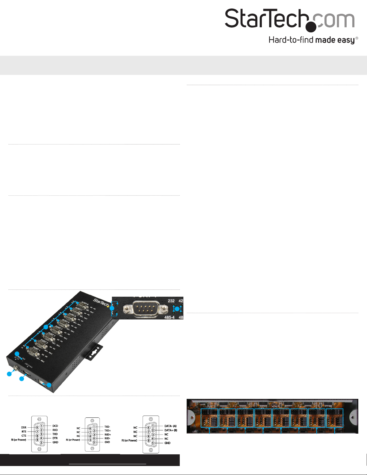
Product diagram
*actual product may vary from photos
Installation
Notes:
• You may need to restart your computer during the software
installation process. Be sure to save any unsaved material before
you install the software.
• Congure your port settings before installing the serial adapter
hub.
1. Download the latest software from the StarTech.com website:
www.StarTech.com/ICUSB234858I.
2. The software that corresponds with your operating system will be
compressed in a .zip folder. Download and extract the contents
of that folder to a location on your computer that’s easy to access,
such as your Desktop or Downloads folder.
3. Open the folder that corresponds with your specic operating
system and launch the installer le.
4. Follow the on-screen prompts to complete the installation, and if
instructed to do so, restart your computer.
5. Connect each of your serial devices to the port you’ve congured
for their connection.
6. Connect the USB-A to USB-B cable to the USB 2.0 port on the
serial adapter hub and to a USB port on your computer.
7. (Optional) If you require AUX power (fully loaded) connect your
power adapter to an AC outlet and the Power adapter port or the
serial adapter hub.
8. (Optional) If you’d like to connect a USB peripheral, like an
additional USB serial hub, to the USB hub port, connect the
peripheral’s USB cable to the USB hub port.
6
1
2
3
4
5
1. RS-232/422/485 ports
2. Power LED
3. Power adapter port
4. USB hub port
5. USB 2.0 port
6. Port send/receive LED
7. Port mode LED
Pinouts
RS-232 mode
For the latest information, technical specications, and support for
this product, please visit www.StarTech.com/ICUSB234858I.
RS-422/RS-485
4-wire mode
RS-485 2-wire
mode
7
Congure port settings
The serial adapter hub supports four dierent modes (RS-232, RS422, RS-485 2-wire, and RS-485 4-wire) with dierent power and
termination options. You can set the mode and settings for each
individual port by adjusting the jumpers inside the serial adapter
hub’s housing. To access the jumpers, open the access panel on the
back of the housing using a Phillips type screwdriver to remove the
two screws.
Jumper groups for each port
Each port has its own set of jumpers that enable you to assign the
settings for each individual port.
Port 1 Port 2 Port 3 Port 4 Port 5 Port 6 Port 7 Port 8
Manual Revision: 03/07/2018
Page 2
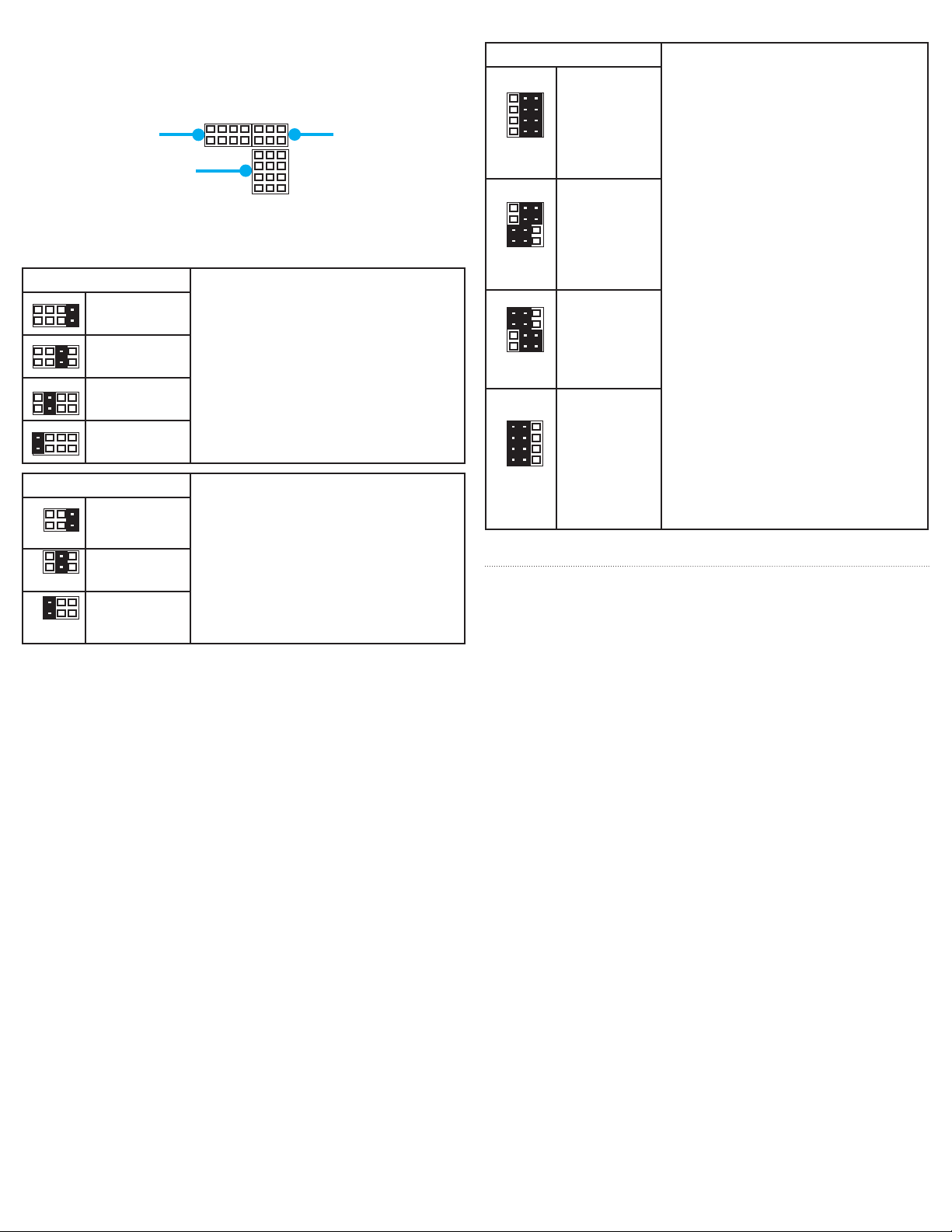
Jumper group settings
There are dierent settings that you can dene for each port: Mode,
Power and Termination. Each setting has its own jumper group used
to dene each port set.
485-2
485-4
422
232RI+5V
Mode group
AUX
Terminators group
ON OFF
The tables below outline the available settings for each jumper
group.
Mode (COM Standard) Use the Mode jumper group to dene
RS-232
(default)
RS-422
the serial communication standard each
port uses.
Note: If the mode is set to RS-232 it’s
important to set all terminations to
RS-485
4-wire
RS-485
2-wire
the o position (see Jumper group
settings, Terminations for details).
Power (Pin-9) Use the Power jumper group to dene
AUX
power adapter
on pin-9
+5V DC
on Pin-9
No power
on pin-9
(default)
the pin-9 power requirements for each
port.
Note: AUX outputs power consistent
with the power adapter connected to
the Power adapter port on the USB to
serial adapter hub.
RX+
RXTX+
TX-
Power group
Jumper group settings cont’d
Terminations Use the Terminations jumper group to
dene which of your send and receive
communication pins are on and o for
each port.
Notes:
• Because RS-232 utilizes dierent
communication pins and additional
signals can cause interference, it’s
recommended that all terminators
be set to o in RS-232 mode.
• While standard terminations for
each mode are recommended, your
termination requirements may vary
depending on your application
and the specic device you’re
ON OFF
ON OFF
ON OFF
Both RX+/
RX- and TX+/TX-
terminators are
disabled
(Terminators for
RS-232 mode)
(default)
TX+/TX-
terminators are
enabled
(Standard
terminators for
RS-485 2-wire
mode)
RX+/RX-
terminators are
enabled
communicating.
Both RX+/
RX- and TX+/TX
ON OFF
terminators are
enabled
(Standard
terminators for
RS-422 and
RS-485 4-wire
mode)
About the LED indicators
The adapter features two sets of LED indicators for each port:
• The Port mode LEDs illuminate solid to indicate what mode each
port is set to.
• The Port send/receive LEDs blink to indicate that data is being sent
or received.
FCC Compliance Statement
This equipment has been tested and found to comply with the limits for a Class B digital device, pursuant to part 15 of the FCC Rules. These limits are designed to provide reasonable protection against
harmful interference in a residential installation. This equipment generates, uses and can radiate radio frequency energy and, if not installed and used in accordance with the instructions, may cause
harmful interference to radio communications. However, there is no guarantee that interference will not occur in a particular installation. If this equipment does cause harmful interference to radio or
television reception, which can be determined by turning the equipment o and on, the user is encouraged to try to correct the interference by one or more of the following measures:
• Reorient or relocate the receiving antenna.
• Increase the separation between the equipment and receiver.
• Connect the equipment into an outlet on a circuit dierent from that to which the receiver is connected.
• Consult the dealer or an experienced radio/TV technician for help
This device complies with part 15 of the FCC Rules. Operation is subject to the following two conditions: (1) This device may not cause harmful interference, and (2) this device must accept any
interference received, including interference that may cause undesired operation. Changes or modications not expressly approved by StarTech.com could void the user’s authority to operate the
equipment.
Industry Canada Statement
This Class B digital apparatus complies with Canadian ICES-003.
Cet appareil numérique de la classe [B] est conforme à la norme NMB-003 du Canada.
CAN ICES-3 (B)/NMB-3(B)
Use of Trademarks, Registered Trademarks, and other Protected Names and Symbols
This manual may make reference to trademarks, registered trademarks, and other protected names and/or symbols of third-party companies not related in any way to
StarTech.com. Where they occur these references are for illustrative purposes only and do not represent an endorsement of a product or service by StarTech.com, or an endorsement of the product(s)
to which this manual applies by the third-party company in question. Regardless of any direct acknowledgement elsewhere in the body of this document, StarTech.com hereby acknowledges that all
trademarks, registered trademarks, service marks, and other protected names and/or symbols contained in this manual and related documents are the property of their respective holders. Phillips is a
registered trademark of the Phillips Screw Company in the United States and other countries. Linux® is the registered trademark of Linus Torvalds in the U.S. and other countries. Windows® is a registered
trademark of Microsoft Corporation in the United States and/or other countries. macOS is a trademarks of Apple Inc., registered in the U.S. and other countries.
Technical Support
StarTech.com’s lifetime technical support is an integral part of our commitment to provide industry-leading solutions. If you ever need help with your product, visit www.startech.com/support and
access our comprehensive selection of online tools, documentation, and downloads.
For the latest drivers/software, please visit www.startech.com/downloads
Warranty Information
This product is backed by a two-year warranty.
StarTech.com warrants its products against defects in materials and workmanship for the periods noted, following the initial date of purchase. During this period, the products may be returned for
repair, or replacement with equivalent products at our discretion. The warranty covers parts and labor costs only. StarTech.com does not warrant its products from defects or damages arising from
misuse, abuse, alteration, or normal wear and tear.
Limitation of Liability
In no event shall the liability of StarTech.com Ltd. and StarTech.com USA LLP (or their ocers, directors, employees or agents) for any damages (whether direct or indirect, special, punitive, incidental,
consequential, or otherwise), loss of prots, loss of business, or any pecuniary loss, arising out of or related to the use of the product exceed the actual price paid for the product. Some states do not
allow the exclusion or limitation of incidental or consequential damages. If such laws apply, the limitations or exclusions contained in this statement may not apply to you.
 Loading...