

Page 1
Sit-Stand Workstation Wall Mount
- Single Monitor
ARMSTSCP1
*actual product may vary from photos
FR: Guide de l’utilisateur - fr.startech.com
DE: Bedienungsanleitung - de.startech.com
ES: Guía del usuario - es.startech.com
NL: Gebruiksaanwijzing - nl.startech.com
PT: Guia do usuário - pt.startech.com
IT: Guida per l’uso - it.startech.com
For the latest information, technical specications, and support for
this product, please visit www.StarTech.com/ARMSTSCP1.
Manual Revision: 09/15/2017
Page 2

Use of Trademarks, Registered Trademarks, and other Protected Names and Symbols
PHILLIPS® is a registered trademark of Phillips Screw Company in the United States or other
countries.
This manual may make reference to trademarks, registered trademarks, and other
protected names and/or symbols of third-party companies not related in any way to
StarTech.com. Where they occur these references are for illustrative purposes only and do not
represent an endorsement of a product or service by StarTech.com, or an endorsement of the
product(s) to which this manual applies by the third-party company in question. Regardless
of any direct acknowledgement elsewhere in the body of this document, StarTech.com hereby
acknowledges that all trademarks, registered trademarks, service marks, and other protected
names and/or symbols contained in this manual and related documents are the property of
their respective holders.
Instruction manual
Page 3

Warning statements
Make sure that you assemble this product according to the instructions.
Read the entire manual and make sure that you understand the instructions before you start to assemble
and use this product.
Never operate this product if parts are missing or damaged.
This product is intended for indoor use only and should not be used outdoors.
When you assemble this product, do not over-tighten the screws. If you encounter resistance while you
are tightening the screws, stop tightening.
Make sure that the weight of the display does not exceed the weight capacity of this product. If you
exceed the weight capacity, you might experience personal injury or damage to the equipment.
Weight capacity of the monitor arm when you use the grommet mount: 4.4 to 17.6 lb. (2 to 8 kg).
Weight capacity of the keyboard tray when you use the grommet mount: 5.6 lb. (2.5 kg).
Weight capacity of the monitor arm when you use the desk clamp assembly: 4.4 to 13.2 lb. (2 to 6 kg.
Weight capacity of the keyboard tray when you use the desk clamp assembly: 3.3 lb. (1.5 kg).
Dichiarazioni di avvertenza
Assicurarsi di Assemblare il prodotto secondo le istruzioni.
Leggere l’intero manuale e assicurarsi di aver compreso tutte le istruzioni prima di iniziare ad assemblare
e a utilizzare questo prodotto.
Non utilizzare il prodotto in presenza di parti mancanti o danneggiate.
Il prodotto è destinato all’uso in ambienti interni. Se ne sconsiglia l’impiego in ambienti esterni.
Durante l’assemblaggio del prodotto, non stringere troppo le viti. Se si incontra resistenza mentre si
stringono le viti, interrompere l’operazione.
Vericare che il peso del display non sia superiore alla capacità di carico del prodotto. Il superamento
della capacità di carico potrebbe causare lesioni personali o danni all’apparecchiatura.
Capacità di carico del monitor quando si usa foro scrivania o morsettiera: 2 a 8 kg.
Capacità di carico della tastiera quando si usa foro scrivania o morsettiera: 2.5 kg.
Capacità di carico del monitor quando si usa morsettiera: 2 a 6 kg.
Capacità di carico della tastiera quando si usa morsettiera: 1.5 kg.
Varningsmeddelanden
Se till att du monterar produkten i enlighet med instruktionerna.
Läs hela manualen och se till att du förstår instruktionerna innan du börjar montera och använda
produkten.
Använd aldrig produkten om delar saknas eller är skadade.
Produkten är endast avsedd för användning inomhus och ska inte användas utomhus.
Dra inte åt skruvarna för hårt när du monterar produkten. Om du måste ta i när du skruvar åt kan
du sluta skruva åt.
Se till att skärmens vikt inte överstiger produktens viktkapacitet. Om viktkapaciteten överstigs kan skada
på person eller utrustning uppstå.
Monitorarms viktkapacitet när du använder kabelhål montering: 2 till 8 kg.
Tangentbordsfackets viktkapacitet när du använder kabelhål montering: 2.5 kg.
Monitorams viktkapacitet när du använder skrivbordsklämma montering: 2 till 6 kg.
Tangentbordsfackets viktkapacitet när du använder skrivbordsklämma montering: 1.5 kg.
Waarschuwingen
Zorg dat u dit product volgens de instructies in elkaar zet.
Lees de gehele handleiding en zorg dat u de instructies begrijpt voordat u dit product in elkaar
zet en gebruikt.
Gebruik dit product nooit als er onderdelen ontbreken of beschadigd zijn.
Dit product is alleen bedoeld voor binnengebruik en mag niet buiten worden gebruikt.
Draai de schroeven niet te strak vast wanneer u dit product in elkaar zet. Als u weerstand voelt tijdens
het vastdraaien van de schroeven, stop dan.
Zorg dat het gewicht van het scherm de maximale capaciteit van dit product niet overschrijdt.
Als u de gewichtscapaciteit overschrijdt, kunt u lichamelijk letsel oplopen of kan schade aan de
apparatuur ontstaan.
Gewichtscapaciteit van de monitor arm wanneer het doorvoergat van uw bureau wordt gebruikt bij
het monteren: 2 til 8 kg.
Gewichtscapaciteit van de toetsenbordhouder wanneer doorvoergat van uw bureau wordt gebruikt
bij het monteren: 2.5 kg.
Gewichtscapaciteit van de monitor arm wanneer de bureau klem wordt gebruikt bij het monteren:
2 til 6 kg.
Gewichtscapaciteit van de toetsenbordhouder wanneer de bureau klem wordt gebruikt bij het
monteren: 1.5 kg.
Warnhinweise
Beachten Sie bei der Montage dieses Produkts die Montageanweisungen.
Bevor Sie dieses Produkt montieren und verwenden, lesen Sie das gesamte Handbuch und vergewissern
Sie sich, dass Sie die Anweisungen verstanden haben.
Das Produkt darf nicht bedient werden, wenn Teile fehlen oder beschädigt sind.
Dieses Produkt ist nur zum Gebrauch in Innenräumen vorgesehen und sollte nicht im Freien
verwendet werden.
Achten Sie bei der Montage des Produkts darauf, die Schrauben nicht zu fest anzuziehen. Sobald Sie
beim Anziehen der Schrauben auf Widerstand stoßen, stellen Sie das Anziehen ein.
Vergewissern Sie sich, dass das Gewicht des Displays die Tragkraft des Produkts nicht überschreitet. Ein
Überschreiten der Tragkraft kann zu Verletzungen oder zur Beschädigung des Produkts führen.
Gewichtskapazität des Monitorarm wenn die kabeldurchführung verwendet wird: 2 nach 8 kg.
Gewichtskapazität der Tastaturhalterung wenn die Kabeldurchführung verwendet wird: 2.5 kg.
Gewichtskapazität des Monitorarm wenn die Tischklemme verwendet wird: 2 nach 6 kg.
Gewichtskapazität der Tastaturhalterung wenn die Tischklemme verwendet wird: 1.5 kg.
Advertencias de uso
Asegúrese de ensamblar este producto según las instrucciones.
Lea todo el manual y asegúrese de haber comprendido bien las instrucciones antes de proceder con el
ensamblaje y el uso de este producto.
Nunca opere o ponga en funcionamiento este producto si faltan piezas o hay daños en las mismas.
El uso de este producto es solo para interiores y no debe utilizarse en exteriores.
Cuando ensamble este producto, no apriete los tornillos más de lo debido. Si al apretar los tornillos
siente resistencia, no los apriete más.
Asegúrese de que el peso del monitor no exceda la capacidad de peso de este producto. Si se excede la
capacidad del peso podrían producirse lesiones personales o daños del equipo.
Capacidad de carga del brazo de monitor cuando se utiliza el soporte de ojal: 2 a 8 kg.
Capacidad de carga de la bandeja de teclado cuando se utiliza el soporte de ojal: 2.5 kg.
Capacidad de carga del brazo de monitor cuando se utiliza el soporte por mordaza: 2 a 6 kg.
Capacidad de carga de la bandeja de teclado cuando se utiliza el soporte por mordaza: 1.5 kg.
Mensagens de aviso
Certique-se de que monta este produto de acordo com as instruções.
Leia todo o manual e certique-se de que entende as instruções antes de começar a montar e a
utilizar este produto.
Nunca opere este produto se faltarem peças ou estas estiverem danicadas.
Este produto destina-se apenas a uma utilização no interior e não deve ser utilizado no exterior.
Quando montar este produto, não aperte demasiado os parafusos. Se encontrar resistência enquanto
aperta os parafusos, pare de apertar.
Certique-se de que o peso do ecrã não excede a capacidade de peso deste produto. Se exceder a
capacidade de peso, poderá sofrer ferimentos pessoais ou danos no equipamento.
Capacidade de carga do braço para monitor quando se monta através de um oricio de ilhó: 2 para 8 kg.
Capacidade de carga do bandeja de teclado quando se monta através de um oricio de ilhó: 2.5 kg.
Capacidade de carga do braço para monitor quando se monta através de uma abraçadeira de
secretária: 2 para 6 kg.
Capacidade de carga do bandeja de teclado quando se monta através de uma abraçadeira de
secretária: 1.5 kg.
Avertissements
Assemblez ce produit conformément aux instructions.
Lisez tout le manuel et assurez-vous que vous comprenez les instructions avant de commencer à
assembler et utiliser ce produit.
N’utilisez pas ce produit si des pièces sont endommagées ou manquantes.
Ce produit est uniquement destiné à une utilisation en intérieur et ne doit pas être utilisé à l’extérieur.
Ne serrez pas trop les vis lors de l’assemblage de ce produit. Si vous rencontrez une résistance lors du
serrage des vis, cessez de serrer.
Vériez que le poids de l’écran ne dépasse pas la capacité pondérale du produit. Si vous dépassez la
capacité pondérale, vous risquez de vous blesser ou d’endommager le matériel.
Capacité de poids pour le bras d’écran quand vous utilisez l’assemblage de passe-ls: 2 à 8 kg.
Capacité de poids pour le le support de clavier quand vous utilisez l’assemblage de passe-ls: 2.5 kg.
Capacité de poids pour le bras d’écran quand vous utilisez l’assemblage de pince de bureau: 2 à 6 kg.
Capacité de poids pour le le support de clavier quand vous utilisez l’assemblage de pince de
bureau: 1.5 kg.
Instruction manual
i
Page 4

注意
必ず取扱説明書に従って本製品の組み立てを行って下さい。
最初に取扱説明書を最後まで読み、本製品の組み立て方をすべて理解してから組み立て作業を
始めて下さい。
本製品は、室内での使用を想定しています。戸外では使用しないで下さい。
本製品は、二人がかりでの組み立てを想定しています。手助けなしに単独で組み立てと設置を行
わないで下さい。
モニタの重量が本製品の最大積載重量を超えないようにして下さい。最大積載重量をオーバーした場
合、怪我をする恐れや器物破損の恐れがあります。
グロメット固定方式を使用した場合のモニタアームの耐荷重 : 2-8 kg.
グロメット固定方式を使用した場合のキーボードトレイの耐荷重 : 2.5 kg.
クランプ固定方式を使用した場合のモニタアームの耐荷重 : 2-6 kg.
クランプ固定方式を使用した場合のキーボードトレイの耐荷重 : 1.5 kg.
Instruction manual
ii
Page 5

Table of Contents
Warnings ...................................................................................................................................................... i
Product dimensions ...............................................................................1
Product diagram ....................................................................................4
Technical specications ........................................................................5
Package contents ...................................................................................7
Requirements .........................................................................................11
Assembly .................................................................................................12
About the attachment options ............................................................................................................ 12
Assemble the base attachment ........................................................................................................... 13
Attach the monitor arm to the base ...................................................................................................27
Attach the column to the keyboard tray ..........................................................................................28
Attach the column to the monitor arm ............................................................................................. 31
Attach the VESA monitor mount to a monitor ...............................................................................34
Attach the monitor to the column ...................................................................................................... 36
Attach the adhesive strip ....................................................................................................................... 38
Route cables ................................................................................................................................................ 39
Remove the monitor ..............................................................................40
Adjusting the ARMSTSCP1....................................................................41
Adjust the tilt angle of the monitor .................................................................................................... 41
Adjust the tilt angle of the keyboard tray ........................................................................................ 42
Counterbalance the weight of the monitor ....................................................................................43
Counterbalance the weight of the workstation .............................................................................44
Adjust the swivel eort of the monitor arm .................................................................................... 45
Extend the keyboard tray ....................................................................................................................... 46
Instruction manual
iii
Page 6

Clean the keyboard tray ........................................................................47
Technical support ................................................................................... 48
Warranty information ............................................................................48
Instruction manual
iv
Page 7
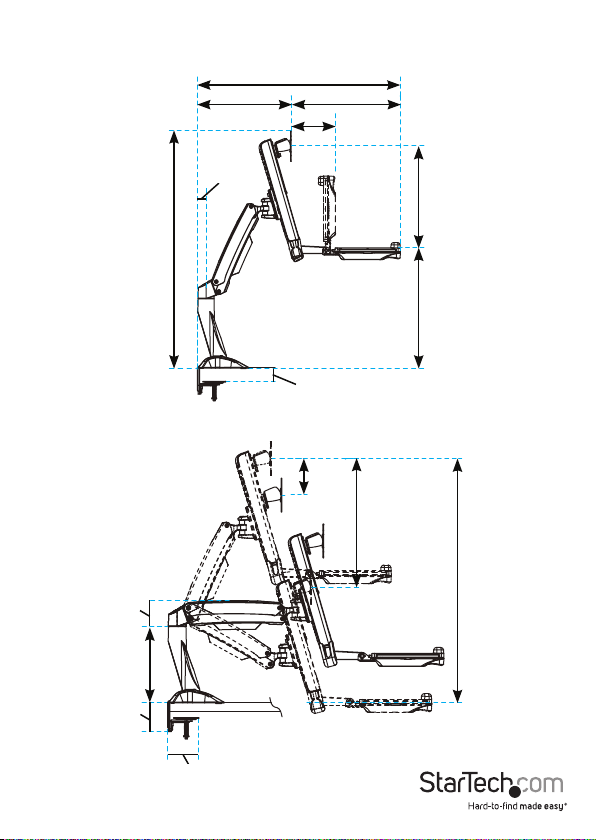
Product dimensions
Max 940 mm (37 in.)
351 mm to 530 mm
(13.8 in. to 20.9 in.)
32.5 mm (1.3 in.)
890 mm (35 in.)
408.7 mm (16.1 in.)
166 mm (6.5 in.)
8 mm to 50 mm
(0.3 in. to 19.6 in.)
124 mm
(4.9 in.)
436 mm
(17.2 in.)
258 mm to 382 mm
14 mm to 450 mm
(10.1 in. to 15 in.)
(0.5 in. to 17.7 in.)
Instruction manual
88 mm
(3.5 in.)
98 mm
(3.9 in.)
260 mm
(10.2 in.)
105.5 mm
(4.1 in.)
396 mm to 832 mm
(15.6 in. to 32.8 in.)
1
Page 8
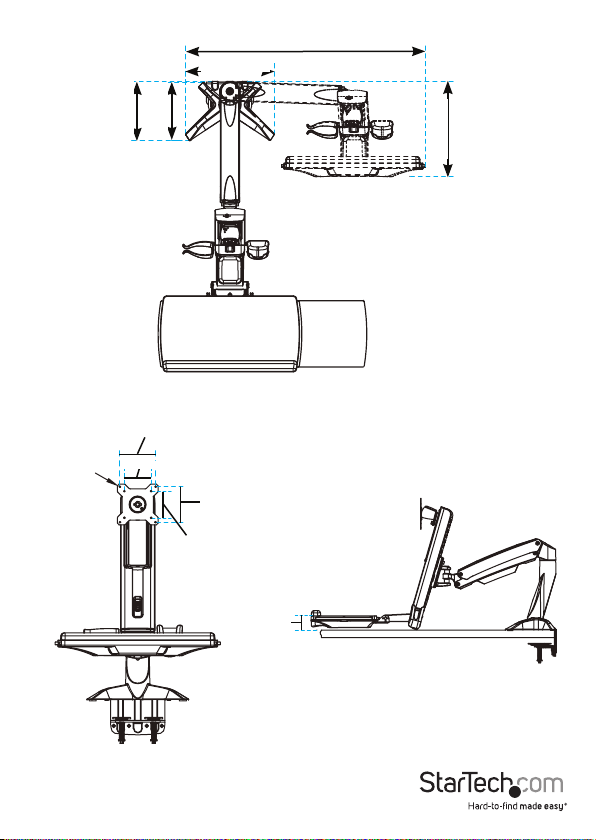
4.5 mm (0.2 in.)
190 mm (7.5 in.)
100 mm (3.9 in.)
75 mm (2.9 in.)
773.2 mm (30.4 in.)
285 mm (11.2 in.)
186 mm (7.3 in.)
308 mm (12.1 in.)
100 mm (3.9 in.)
75 mm (2.9 in.)
Instruction manual
52 mm (2 in.)
2
Page 9

64 mm (2.5 in.)
44 mm (1.7 in.)
8 to 217 mm
(0.3 in. to 8.5 in.)
207 mm
530 mm (20.9 in.)
351 mm (13.8 in.)
(8.1 in.)
449 mm (17.7 in.)
668 mm (26.3 in.)
8 to 217 mm
(0.3 in. to 8.5 in.)
213 mm
255 mm
(8.4 in.)
489 mm (19.2 in.)
(10 in.)
Instruction manual
3
Page 10
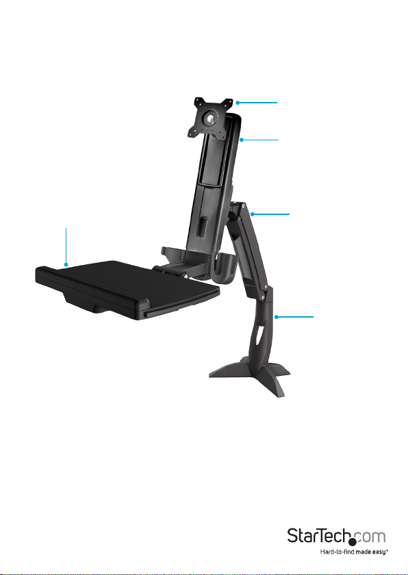
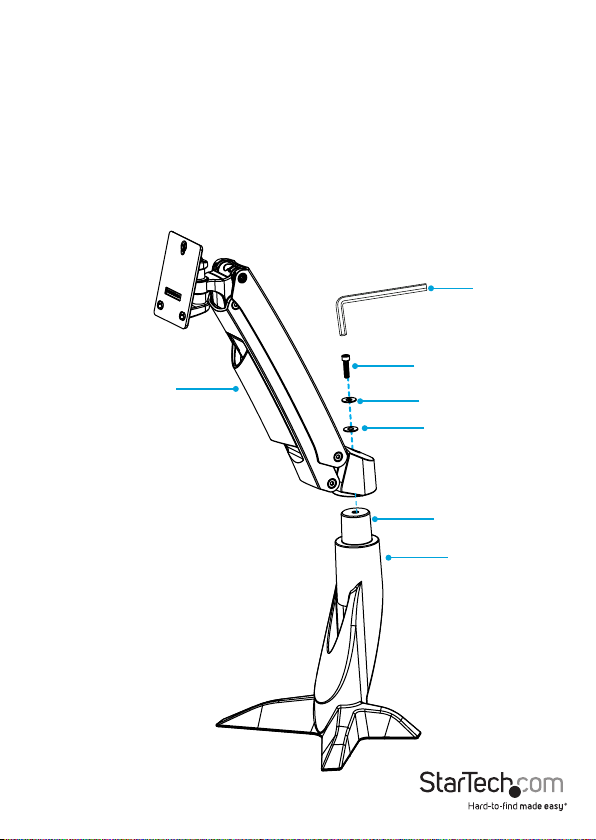
Product diagram
Grommet feature pictured
VESA monitor mount
Column
Keyboard tray
Instruction manual
Monitor arm
Base
4
Page 11
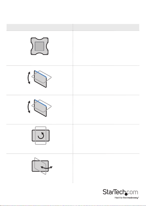
Technical specications
Type of measurement Measurement
VESA
Tilt (monitor)
Tilt (keyboard)
Pivot (monitor)
75 x 75 mm
100 x 100 mm
-5° to +35°
0° to +90°
360°
Swivel (monitor arm)
Instruction manual
+/-90°
5
Page 12
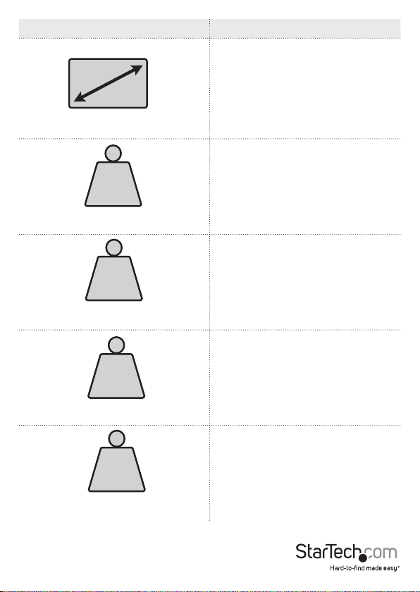
Type of measurement Measurement
24 in. or less
Supported monitor size
LB
kg
Supported weight of the monitor arm
when you use the desk clamp
LB
kg
Supported weight of the keyboard tray
when you use the desk clamp
LB
kg
Supported weight of the monitor arm
when you use the grommet mount
LB
kg
Supported weight of the keyboard tray
when you use the grommet mount
Instruction manual
4.4 to 13.2 lb. (2 to 6 kg)
3.3 lb. (1.5 kg)
4.4 to 17.6 lb. (2 to 8 kg)
5.6 lb. (2.5 kg)
6
Page 13
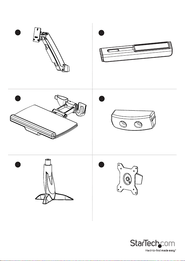
Package contents
1
Monitor arm
Qty: One
3
Keyboard tray
Qty: One
5 6
Base
Qty: One
2
Column
Qty: One
4
Keyboard tray cap
Qty: One
VESA monitor mount
Qty: One
Instruction manual
7
Page 14
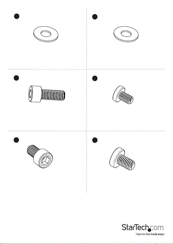
7
8
9
11
Plastic washer
Qty: One
M8x20 mm screw
Qty: One
M6x12 mm screws
Qty: Four
Metal washer
Qty: One
10
M6x25 mm screws
Qt y: Two
12
M6x10 mm screws
Qty: Three
Instruction manual
8
Page 15
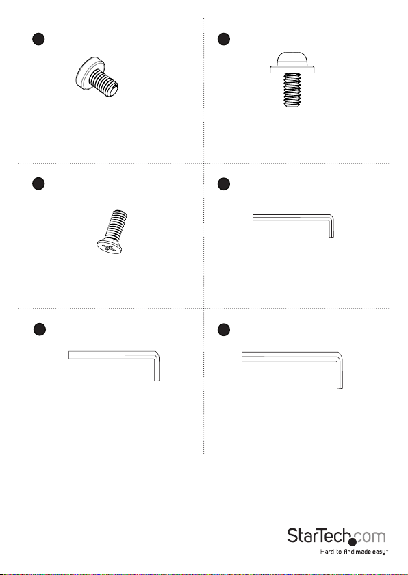
13
14
M6x8 mm screw
Qty: One
15
Base screws
Qty: Four
17
5 mm hex key
Qty: One
M4x10 mm screws
Qty: Four
16
2.5 mm hex key
Qty: One
18
6 mm hex key
Qty: One
Instruction manual
9
Page 16
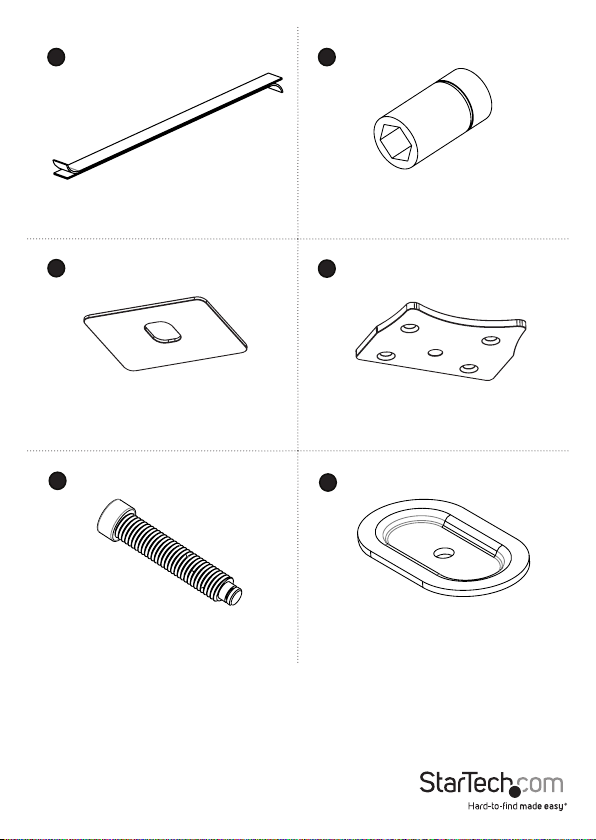
2019
Adhesive strip
Qty: One
21
22
Base pad
Qty: One
23
24
M8x65 screw
Qty: One
Socket driver
Qty: One
Base plate
Qty: One
Grommet plate
Qty: One
Instruction manual
10
Page 17
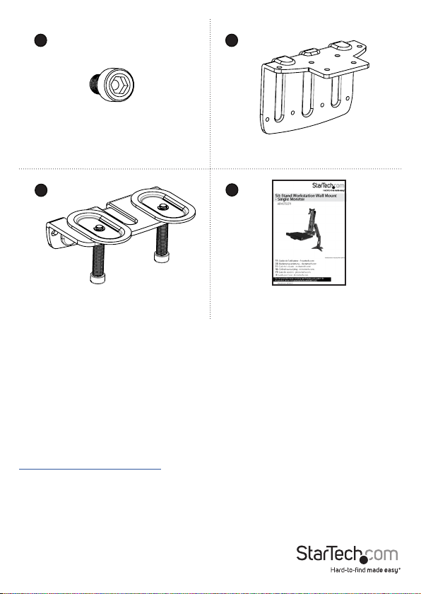
25 26
Clamp screws
Qty: Four
27
Clamp screw assembly
Qty: One
28
Clamp L bracket
Qty: One
Instruction manual
Qty: One
Requirements
• A monitor that is compatible with one of the VESA mounting hole patterns that
ARMSTSCP1 supports
• A Phillips type screwdriver
Requirements are subject to change. For the latest requirements, please visit
www.StarTech.com/ARMSTSCP1.
Instruction manual
11
Page 18

Assembly
About the attachment options
The ARMSTSCP1 features a grommet assembly and a desk clamp option for attaching
the ARMSTSCP1 to a desk or table.
Requirements to use the grommet assembly to attach the ARMSTSCP1:
• Table or desk with a grommet hole
• Table or desk that is between 0.3 and 2 inches (8 to 50 mm) thick
• Monitor that weighs between 4.4 and 17.6 lb. (2 to 8 kg)
Note: When you use the grommet assembly to attach the ARMSTSCP1, the keyboard
tray supports up to 5.6 lb. (2.5 kg) of weight.
Requirements to use the desk clamp to attach the ARMSTSCP1:
• A table or desk that is between 0.3 and 2 inches (8 to 50 mm) thick
• At least 0.3 inches (8 mm) of clearance between the table or desk and the wall
• Monitor that weighs between 4.4 and 13.2 lb. (2 to 6 kg)
Note: When you use the grommet assembly to attach the ARMSTSCP1, the keyboard
tray supports up to 3.3 lb. (1.5 kg) of weight.
Instruction manual
12
Page 19

Assemble the base attachment
Based on your setup, follow the steps to attach the grommet assembly or the desk
clamp.
Attach the grommet assembly
1. Line up the base plate with the assembly holes on the underside of the base.
2. Insert the four base screws through the base plate and into the base. (gure 1)
3. Use a Phillips type screwdriver to tighten the screws.
gure 1
Base
Base plate
Instruction manual
Base screws
Screwdriver
13
Page 20

4. Remove the adhesive backing from the base pad and ax the base pad to the
underside of the base. (gure 2)
gure 2
Base
Base pad
Instruction manual
14
Page 21

5. Position the base over the grommet hole in your desk or table.
6. Thread the M8x65 screw up through the underside of the grommet plate.
7. Place the grommet plate and screw assembly against the grommet hole on the
underside of your desk or table.
8. Insert the M8x65 screw through the grommet plate and into the base.
9. Use the 6 mm hex key to tighten the M8x65 screw until the plate is tight against
your desk or table. (gure 3)
gure 3
Base
8 and 50 mm
Instruction manual
Grommet plate
M8x65 screw
6 mm hex key
15
Page 22

Attach the desk clamp to a desk or table against a wall
To attach the desk clamp to a desk or table that is against a wall, you need at least
8 mm of space between the edge of the surface that you’re attaching the ARMSTSCP1
to and the wall.
1. Line up the clamp L bracket with the assembly holes on the underside of the base.
2. Insert the four base screws through the clamp L bracket and into the base. (gure 4)
3. Use a Phillips type screwdriver to tighten the screws.
gure 4
Base
Base screws
Clamp L bracket
Instruction manual
Screwdriver
16
Page 23

4. Remove the adhesive backing from the base pad and ax the base pad to the
underside of the clamp L bracket. (gure 5)
gure 5
Base
Clamp L bracket
Instruction manual
Base pad
17
Page 24

5. Slide the base between the desk or table and the wall. (gure 6)
gure 6
Base
Min 8 mm
Instruction manual
18
Page 25

6. Line up the clamp screw assembly with the assembly holes in the clamp L bracket.
(gure 7)
gure 7
Clamp L bracket
Instruction manual
Clamp screw assembly
19
Page 26

7. Insert the four clamp screws through the clamp screw assembly and into the clamp
L bracket.
8. Use the 5 mm hex key to tighten the screws. (gure 8)
gure 8
Clamp screws
5 mm hex key
Instruction manual
20
Page 27

9. Use the 6 mm hex key to tighten the screws in the clamp screw assembly until the
plates are tight against your desk or table. (gure 9)
gure 9
Plate
Screw
6 mm hex key
Instruction manual
21
Page 28

Attach the desk clamp to a desk or table
1. Line up the clamp L bracket with the assembly holes on the underside of the base.
2. Insert the four base screws through the base plate and into the base. (gure 10)
3. Use a Phillips type screwdriver to tighten the screws.
gure 10
Base
Base screws
Clamp L bracket
Instruction manual
Screwdriver
22
Page 29

4. Remove the adhesive backing from the base pad and ax the base pad to the
underside of the base. (gure 11)
gure 11
Base
Clamp L bracket
Instruction manual
Base pad
23
Page 30

5. Line up the clamp screw assembly with the assembly holes in the clamp L bracket.
6. Insert the four clamp screws through the clamp screw assembly and into the clamp
L bracket.
7. Use the 5 mm hex key to tighten the screws. (gure 12)
gure 12
Base
Clamp L bracket
Instruction manual
Clamp screws
5 mm hex key
Clamp screw assembly
24
Page 31

8. Slide the assembly over the edge of your desk or table. (gure 13)
gure 13
Base
8 and 50 mm
Instruction manual
25
Page 32

9. Use the 6 mm hex key to tighten the screws in the clamp screw assembly until the
plates are tight against your desk or table. (gure 14)
gure 14
Plate
Instruction manual
Screw
6 mm hex key
26
Page 33
Attach the monitor arm to the base
1. Place the monitor arm onto the projection on the base.
2. Place the plastic washer into the joint in the monitor arm.
3. Place the metal washer onto the plastic washer.
4. Insert the M8x20 mm screw through the washers and into the joint in the monitor
arm.
5. Use the 6 mm hex key to tighten the screw. (gure 15)
gure 15
6 mm hex key
M8x20 mm screw
Monitor arm
Metal washer
Plastic washer
Projection
Base
Instruction manual
27
Page 34

Attach the column to the keyboard tray
1. Position the column with the cutout at the bottom half of the column.
2. Line up the assembly holes on the bottom of the column with the assembly holes
between the holders on the keyboard tray. (gure 16)
gure 16
Column
Holder
Holder
Keyboard tray
Instruction manual
28
Page 35

3. On the underside of the keyboard tray, insert the four M6x12 mm screws through
the keyboard tray and into the column. (gure 17)
4. Use the 5 mm hex key to tighten the screws in place.
gure 17
5 mm hex key
Instruction manual
M6x12 mm screw
Keyboard tray
29
Page 36

5. On the underside of the keyboard tray, place the keyboard tray cap over the
assembly holes.
6. Insert the two M6x25 mm screws into the keyboard tray cap and keyboard tray.
(gure 18)
7. Use the 6 mm hex key to tighten the screws in place.
gure 18
6 mm hex key
M6x25 mm screw
Keyboard tray cover
Instruction manual
30
Page 37

Attach the column to the monitor arm
1. Insert one of the M6x10 mm screws into the top hole in the plate on the back of the
column. (gure 19)
Note: Do not tighten the M6x10 mm screw and make sure that you leave between 4
and 5 mm of space between the plate and the screw.
gure 19
Column
M6x10 mm screw
Instruction manual
31
Page 38

2. Hook the M6x10 mm screw attached to the column into the key-shaped hole at the
top of the plate on the monitor arm. (gure 20)
gure 20
M6x10 mm screw
Key-shaped hole
Monitor arm
Instruction manual
32
Page 39

3. Insert the M6x10 mm screws into the lower two holes on the plate on the monitor
arm. (gure 21)
4. Use the 5 mm hex key to tighten all three of the screws.
gure 21
Monitor arm
M6x10 mm screw
5 mm hex key
Instruction manual
33
Page 40

Attach the VESA monitor mount to a monitor
1. If you want to be able to rotate your monitor 360°, use a Phillips type screwdriver to
remove the screw from the VESA monitor mount. (gure 22)
gure 22
VESA monitor mount
Screw
Screwdriver
Instruction manual
34
Page 41

2. Position the VESA monitor mount so that the projection on the back of the VESA
monitor mount is pointing towards the bottom of the monitor.
3. Line up the VESA monitor mount with the mounting holes on the back of the
monitor.
4. Insert the M4x10 mm screws through the VESA monitor mount and into the back of
the monitor.
5. Use a Phillips type screwdriver to tighten the screws. (gure 23)
Warning! Do not over-tighten the screws. If you encounter resistance while you’re
tightening the screws, stop tightening. Failure to do so could result in damage to the
monitor.
gure 23
Screwdriver
M4x10 mm screw
Bottom of
monitor
Instruction manual
VESA monitor mount
35
Page 42

Attach the monitor to the column
1. Carefully hook the back of the VESA monitor mount onto the plate on the column.
(gure 24)
gure 24
VESA monitor mount
Column
Instruction manual
36
Page 43

2. Insert the M6x8 mm screw through the bottom of the VESA monitor mount and into
the plate on the column. (gure 25)
3. Use the 5 mm hex key to tighten the screw.
gure 25
VESA monitor mount
M6x8 mm screw
5 mm hex key
Instruction manual
37
Page 44

Attach the adhesive strip
1. If necessary, cut the adhesive strip to t the length of your keyboard.
2. Separate the two sides of the adhesive strip.
3. Remove the backing from one half of the adhesive strip and stick it to the back of
your keyboard.
4. Remove the backing from the other half of the adhesive strip and stick it to the
surface of the keyboard tray so that it lines up with the strip that you attached to
your keyboard. (gure 26)
gure 26
Keyboard
Instruction manual
Adhesive strip
38
Page 45

Route cables
1. Run your cable along the column and through the slot at the bottom of the column.
2. At the top of the cable cover, squeeze the tabs and gently pull the cable cover from
the monitor arm.
3. Slide the cable cover up to unhook the tabs at the bottom of the cable cover from
the slots in the monitor arm, and lift the cable cover o of the monitor arm.
Caution! Be careful not to snap o the tabs from the cable cover when you remove it.
4. Run the cable along the inside of the cable cover. (gure 27)
5. Hook the tabs at the bottom of the cable cover into the slots in the monitor arm,
and push the tabs at the top of the cable cover into the corresponding slots.
gure 27
Monitor arm
Cable
Tab
Cable cover
Instruction manual
Tab
39
Page 46

Remove the monitor
Warning: Stored energy hazard! The column contains a lift mechanism that could
move up quickly when you remove the monitor from the product. Before you remove
the monitor, move the ARMSTSCP1 to the highest position. Failure to do so could result
in injury or property damage.
1. Move the ARMSTSCP1 to the highest position it can go. (gure 28)
2. Use the M5 hex key to remove the M6x8 mm screw from the bottom of the VESA
monitor mount.
3. Carefully lift the monitor o of the monitor mount.
gure 28
Monitor
ARMSTSCP1 in upright position
5 mm hex key
Instruction manual
40
Page 47

Adjusting the ARMSTSCP1
Adjust the tilt angle of the monitor
• To increase or decrease the tilt, use the 2.5 mm hex key and adjust the screw in the
top of the VESA monitor mount. (gure 29)
gure 29
VESA monitor mount
Adjustment screw
2.5 mm hex key
Instruction manual
41
Page 48

Adjust the tilt angle of the keyboard tray
• Pull up or push down on the keyboard tray to adjust it from 0 to 90°. (gure 30)
gure 30
Keyboard tray
Instruction manual
42
Page 49

Counterbalance the weight of the monitor
The ARMSTSCP1 features a one-touch height adjustment design that enables you to
easily raise or lower your monitor. To use the one-touch height adjustment feature, you
need to counterbalance the weight of your monitor.
• If the monitor doesn’t stay in position when you move it or it’s dicult to raise or
lower it, use the 5 mm hex key to turn the screw in the top of the column to the
right or the left. (gure 31)
gure 31
Column
Instruction manual
Adjustment screw
5 mm hex key
43
Page 50

Counterbalance the weight of the workstation
The ARMSTSCP1 features a one-touch height adjustment design that enables you to
easily raise or lower the entire workstation, including the keyboard tray. To use the
one-touch height adjustment feature, you need to counterbalance the weight of the
workstation.
• If the workstation doesn’t stay in position when you move it or it’s dicult to raise
or lower it, use the socket driver to adjust the screw in the hinge of the monitor arm.
(gure 32)
gure 32
Adjustment screw
Instruction manual
44
Page 51

Adjust the swivel eort of the monitor arm
• To increase or decrease the swivel eort of the monitor arm, use the 6 mm hex key
to turn the screw in the plate on the back of the column to the right or left.
(gure 33)
Caution! When you loosen the screw, make sure that you don’t remove the screw from
the joint. If you remove the screw, the column will fall o of the monitor arm and your
equipment could be damaged or you could be injured.
gure 33
6 mm hex key
Adjustment screw
Instruction manual
45
Page 52
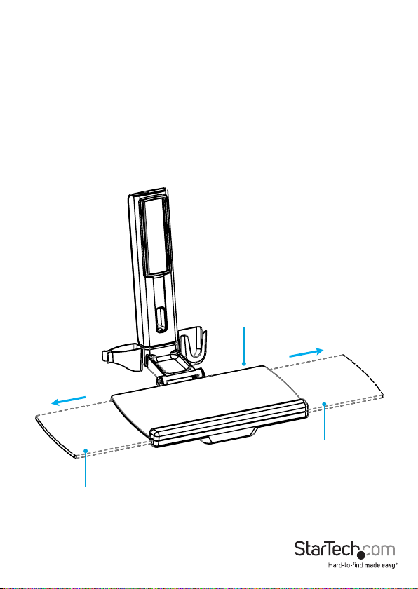
Extend the keyboard tray
You can adjust the keyboard tray so that it extends to the left or right.
• Pull the extension to the left or right.
(gure 34)
gure 34
Keyboard tray
Extension
Instruction manual
Extension
46
Page 53

Clean the keyboard tray
You can remove the extension and the plastic cover from the wrist rest to clean them.
1. To remove the plastic cover from the wrist rest, carefully peel it o of the keyboard
tray. (gure 35)
2. To remove the keyboard tray extension, pull the extension all of the way out. On the
underside of the keyboard tray, insert a blunt pin into one of the two holes, depress
the clip, and pull the extension out of the keyboard tray. (gure 36)
3. Clean the keyboard tray components with warm water and a non-abrasive cleaner.
gure 35
Wrist rest
gure 36
Instruction manual
Extension
Hole
Extension
Hole
47
Page 54

Technical support
StarTech.com’s lifetime technical support is an integral part of our commitment to
provide industry-leading solutions. If you ever need help with your product, visit
www.startech.com/support and access our comprehensive selection of online tools,
documentation, and downloads.
For the latest drivers/software, please visit www.startech.com/downloads
Warranty information
This product is backed by a two-year warranty.
StarTech.com warrants its products against defects in materials and workmanship
for the periods noted, following the initial date of purchase. During this period,
the products may be returned for repair, or replacement with equivalent
products at our discretion. The warranty covers parts and labor costs only.
StarTech.com does not warrant its products from defects or damages arising from
misuse, abuse, alteration, or normal wear and tear.
Limitation of liability
In no event shall the liability of StarTech.com Ltd. and StarTech.com USA LLP (or their
ocers, directors, employees or agents) for any damages (whether direct or indirect,
special, punitive, incidental, consequential, or otherwise), loss of prots, loss of business,
or any pecuniary loss, arising out of or related to the use of the product exceed the
actual price paid for the product. Some states do not allow the exclusion or limitation
of incidental or consequential damages. If such laws apply, the limitations or exclusions
contained in this statement may not apply to you.
Instruction manual
48
Page 55

Hard-to-nd made easy. At StarTech.com, that isn’t a slogan. It’s a promise.
StarTech.com is your one-stop source for every connectivity part you need. From
the latest technology to legacy products — and all the parts that bridge the old and
new — we can help you nd the parts that connect your solutions.
We make it easy to locate the parts, and we quickly deliver them wherever they need
to go. Just talk to one of our tech advisors or visit our website. You’ll be connected to
the products you need in no time.
Visit www.startech.com for complete information on all StarTech.com products and
to access exclusive resources and time-saving tools.
StarTech.com is an ISO 9001 Registered manufacturer of connectivity and technology
parts. StarTech.com was founded in 1985 and has operations in the United States,
Canada, the United Kingdom and Taiwan servicing a worldwide market.
 Loading...