

Page 1
Single-Monitor Arm - One-Touch Height
Adjustment - Heavy Duty
Actual product may vary from photos
User Manual
SKU#: ARMPIVOTHD & ARMPIVOTHDB
For the latest information and specications visit
www.startech.com/ARMPIVOTHD
Manual Revision: 06/27/2018
Page 2

Compliance Statements
FCC Compliance Statement
This equipment has been tested and found to comply
with the limits for a Class B digital device, pursuant to part
15 of the FCC Rules. These limits are designed to provide
reasonable protection against harmful interference in a
residential installation. This equipment generates, uses and
can radiate radio frequency energy and, if not installed and
used in accordance with the instructions, may cause harmful
interference to radio communications. However, there is
no guarantee that interference will not occur in a particular
installation. If this equipment does cause harmful interference
to radio or television reception, which can be determined by
turning the equipment o and on, the user is encouraged to
try to correct the interference by one or more of the following
measures:
• Reorient or relocate the receiving antenna
• Increase the separation between the equipment and receiver
• Connect the equipment into an outlet on a circuit dierent
from that to which the receiver is connected
• Consult the dealer or an experienced radio/TV technician for
help
Use of Trademarks, Registered Trademarks, and other
Protected Names and Symbols
This manual may make reference to trademarks, registered
trademarks, and other protected names and/or symbols of
third-party companies not related in any way to StarTech.com.
Where they occur these references are for illustrative purposes
only and do not represent an endorsement of a product or
To view manuals, videos, drivers, downloads, technical drawings, and more visit www.startech.com/support
1
Page 3

service by StarTech.com, or an endorsement of the product(s)
to which this manual applies by the third-party company
in question. Regardless of any direct acknowledgement
elsewhere in the body of this document, StarTech.com hereby
acknowledges that all trademarks, registered trademarks,
service marks, and other protected names and/or symbols
contained in this manual and related documents are the
property of their respective holders.
To view manuals, videos, drivers, downloads, technical drawings, and more visit www.startech.com/support
2
Page 4

Safety Statements
Safety Measures
• Wiring terminations should not be made with the product and/or electric
lines under power.
• Product installation and/or mounting should be completed by a certied
professional as per the local safety and building code guidelines.
• Cables (including power and charging cables) should be placed and routed
to avoid creating electric, tripping or safety hazards.
Mesures de sécurité
• Les terminaisons de câblâge ne doivent pas être eectuées lorsque le produit
et/ou les câbles électriques sont sous tension.
• L’installation et/ou le montage du produit doit être réalisé par un
professionnel certié et dans le respect des normes locales et du code de
construction local.
• Les câbles (y compris les câbles d’alimentation et de chargement) doivent
être placés et acheminés de façon à éviter tout risque électrique, de chute ou
de sécurité
安全対策
• 電源が入っている状態の製品または電線の終端処理を行わないでください。
• 製品の設置やマウントは、使用地域の安全ガイドラインおよび建築基準に従い、有資格の専門業者が行うようにしてください。
• ケーブル(電源ケーブルと充電ケーブルを含む)は、適切な配置と引き回しを行い、電気障害やつまづきの危険性など、安全上のリスクを回避するよう
にしてください。
Misure di sicurezza
• I terminiali dei li elettrici non devono essere realizzate con il prodotto e/o le
linee elettriche sotto tensione.
• L’installazione e/o il montaggio dei prodotti devono essere eseguiti da un
tecnico professionale certicato che conosca le linee guida locali sulle norme
edilizie e sulla sicurezza.
• I cavi (inclusi i cavi di alimentazione e di ricarica) devono essere posizionati
e stesi in modo da evitare pericoli di inciampo, rischi di scosse elettriche o
pericoli per la sicurezza.
Säkerhetsåtgärder
• Montering av kabelavslutningar får inte göras när produkten och/eller
elledningarna är strömförda.
• Installation och/eller montering får endast göras av behöriga yrkespersoner
och enligt gällande lokala förordningar för säkerhet och byggnormer.
• Kablar (inklusive elkablar och laddningskablar) ska dras och placeras på så
sätt att risk för snubblingsolyckor och andra olyckor kan undvikas.
To view manuals, videos, drivers, downloads, technical drawings, and more visit www.startech.com/support
3
Page 5

Warning Statements
Make sure to assemble this product according to the instructions. Failure to do
so might result in personal injury or property damage.
Make sure that the weight of the monitor doesn’t exceed the weight capacity of
this product. If you exceed the weight capacity, you might experience personal
injury or damage to the equipment. This product can support the following
weight: 19.8 lb. (9 kg).
Never operate this product if parts are missing or damaged.
Allowing any part of your component cables to get caught between moveable
parts might result in personal injury or damage to your equipment.
Varningsmeddelanden
Se till att du monterar produkten i enlighet med instruktionerna. Om du inte gör
det kan skada på person eller egendom uppstå.
Se till att skärmens vikt inte överstiger produktens viktkapacitet. Om
viktkapaciteten överstigs kan skada på person eller utrustning uppstå. Denna
produkt har stöd för följande vikter: 9 kg.
Använd aldrig produkten om delar saknas eller är skadade.
Om någon del av dina komponentkablar fastnar mellan rörliga delar kan skada
på person eller utrustning uppstå.
Avertissements
Assemblez ce produit conformément aux instructions. Si vous ne respectez pas
ces instructions, vous risquez de vous blesser ou d’endommager l’équipement.
Vériez que le poids du moniteur ne dépasse pas la capacité pondérale du
produit. Si vous dépassez la capacité pondérale, vous risquez des blessures
corporelles ou des dommages matériels. Ce produit peut supporter 9 kg.
N’utilisez pas ce produit si des pièces sont endommagées ou manquantes.
Si les câbles des composants se coincent entre des parties mobiles, vous risquez
des blessures corporelles ou des dommages matériels.
Warnhinweise
Montieren Sie dieses Produkt gemäß den Anweisungen. Anderenfalls kann dies
zu Verletzungen von Personen oder Schäden an Eigentum führen.
Das Gewicht des Monitors darf die zulässige Traglast des Produkts nicht
übersteigen. Wenn die Traglast überschritten wird, kann dies zu Verletzungen
von Personen oder Schäden an Geräten führen. Dieses Produkt ist für folgendes
To view manuals, videos, drivers, downloads, technical drawings, and more visit www.startech.com/support
4
Page 6

Gewicht geeignet: 9 kg.
Das Produkt darf nicht bedient werden, wenn Teile fehlen oder beschädigt sind.
Wenn sich Komponentenkabel in beweglichen Teilen verfangen, kann dies zu
Verletzungen von Personen oder Schäden an Geräten führen.
Dichiarazioni di avvertenza
Assemblare il prodotto rispettando le istruzioni. Il mancato rispetto delle
istruzioni potrebbe causare danni a persone o proprietà.
Vericare che il peso del monitor non superi la capacità di supporto del
prodotto. In caso di superamento della capacità di supporto potrebbero
vericarsi danni a persone o apparecchiature. Il prodotto è in grado di
supportare i seguenti pesi: 9 kg.
Non utilizzare il prodotto in presenza di parti mancanti o danneggiate.
L’eventuale intrappolamento dei cavi del componente fra elementi in
movimento potrebbe causare danni a persone o apparecchiature.
Mensagens de aviso
Certique-se de que monta este produto de acordo com as instruções. O
incumprimento pode resultar em ferimentos pessoais ou danos de propriedade.
Certique-se de que o peso do monitor não excede a capacidade de peso deste
produto. Se exceder a capacidade de peso, pode sofrer ferimentos pessoais ou
danos no equipamento. Este produto pode suportar o seguinte peso: 9 kg.
Nunca opere este produto se faltarem peças ou estas estiverem danicadas.
Ao permitir que qualquer parte dos cabos do seu componente que preso
entre partes móveis, pode resultar em ferimentos pessoais ou danos no seu
equipamento.
Advertencias de uso
Asegúrese de ensamblar este producto según las instrucciones. De lo contrario,
pueden producirse lesiones personales o daños de propiedad.
Asegúrese de que el peso del monitor no exceda la capacidad de carga de
este producto. Si se excede dicha capacidad se podrían producirse lesiones
personales o daños al equipo. Este producto tiene capicidad para el siguiente
peso: 9 kg.
Nunca opere o ponga en funcionamiento este producto si faltan piezas o hay
daños en las mismas.
En caso de que los cables de su componente queden atascados en piezas en
To view manuals, videos, drivers, downloads, technical drawings, and more visit www.startech.com/support
5
Page 7

movimiento se pueden producir lesiones personales o daños en el equipo.
Waarschuwingen
Zorg dat dit product volgens de instructies in elkaar wordt gezet. Indien dit niet
goed gebeurt kan lichamelijk letsel of materiële schade ontstaan.
Zorg dat het gewicht van het scherm de maximale capaciteit van dit product
niet overschrijdt. Als u de gewichtscapaciteit overschrijdt, kan persoonlijk letsel
of schade aan de apparatuur ontstaan. Dit product ondersteunt het volgende
gewicht: 9 kg.
Gebruik dit product nooit als er onderdelen ontbreken of beschadigd zijn.
Als uw componentkabels tussen bewegende delen vast komen te zitten, kan dit
lichamelijk letsel of schade aan de apparatuur veroorzaken.
注意
必ず取扱説明書に従って本製品の組み立てを行って下さい。取り扱いを誤った場
合に、傷害を負う恐れや物的損害が発生する恐れがあります。
取り付けるモニターの重量が、本製品で定められた最大積載重量を超えないよう
にして下さい。最大積載重量をオーバーした場合、傷害を負う恐れやモニターや
本製品に損害が発生する恐れがあります。本製品は、モニター1台あたり9kgまで
支持できます。
本製品で使用している部品の一部が紛失していたり損傷している状態で使用す
るのは絶対に止めて下さい。
ケーブルの一部が本製品の可動部に引っ掛かってしまった場合、傷害を負う恐れ
やモニターや本製品に損害が発生する恐れがあります。
To view manuals, videos, drivers, downloads, technical drawings, and more visit www.startech.com/support
6
Page 8

Table of Contents
Compliance Statements ........................................................................1
Safety Statements ..................................................................................3
Warning Statements ..............................................................................4
Technical Specication ..........................................................................8
Package Contents...................................................................................10
Requirements .........................................................................................13
Assembly .................................................................................................13
Use the Desk Clamp to Attach the Arm Mount .............................................................................. 13
Use the Grommet Mount to Attach the Arm Mount .................................................................... 14
Attach a Monitor........................................................................................................................................15
Adjust the Spring Arm ...........................................................................17
Routing the Cables ................................................................................................................................... 17
Adjust the Position of the Arm Mount ................................................18
To view manuals, videos, drivers, downloads, technical drawings, and more visit www.startech.com/support
7
Page 9
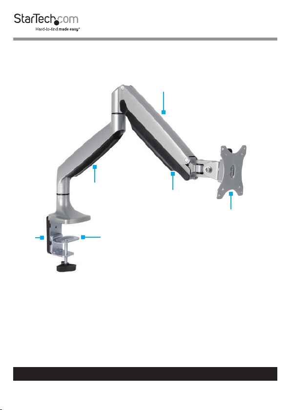
Product Diagram
Spring Arm
Lower Cable
Cover
Upper Cable
Cover
VESA Monitor
Hex
Key
Desk Clamp
Mount
Holder
To view manuals, videos, drivers, downloads, technical drawings, and more visit www.startech.com/support
8
Page 10
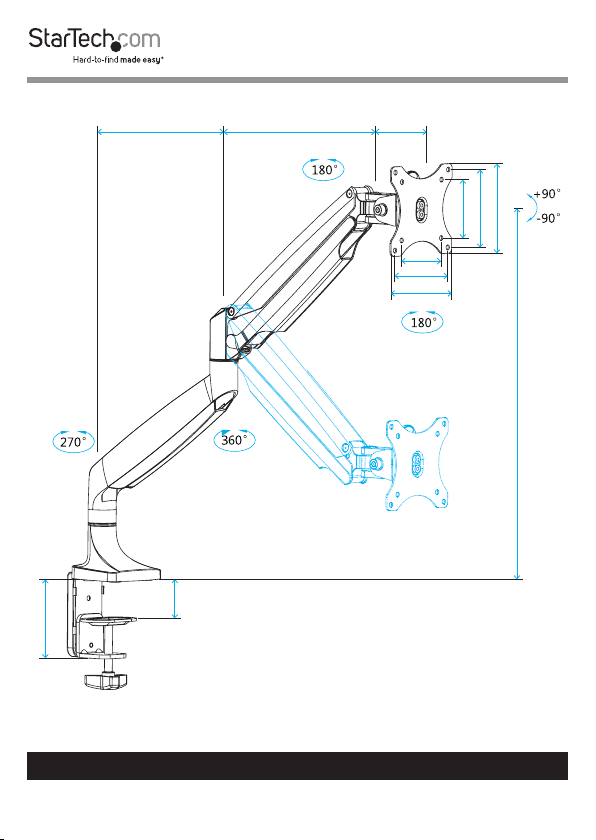
Product Dimensions
100 mm
80 mmmin 255 mm to max 315 mm210 mm
75 mm
100 mm
115 mm
75 mm
100 mm
115 mm
min 170 mm to max 505 mm
min 10 mm to max 85 mm
To view manuals, videos, drivers, downloads, technical drawings, and more visit www.startech.com/support
9
Page 11
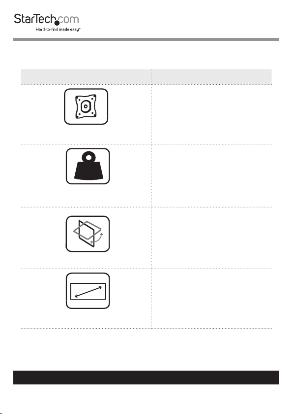
Technical Specication
Type of Measurement Measurement
VESA Mounting Hole Pattern
Up to 9 kg (19.8 lb.)
kg
Weight Capacity
Tilt
Max 813 mm (32 in.)
Screen Size
75x75
100x100
+90 to -90
To view manuals, videos, drivers, downloads, technical drawings, and more visit www.startech.com/support
10
Page 12
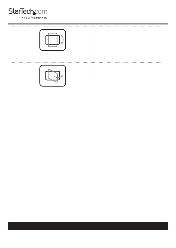
Rotate
Swivel
180
180
To view manuals, videos, drivers, downloads, technical drawings, and more visit www.startech.com/support
11
Page 13
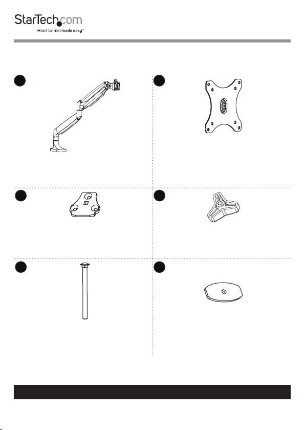
Package Contents
1
Spring Arm
Qty: One
3
Grommet Base Plate
Qty: One
5
Grommet Screw
Qty: One
2
VESA Monitor Mount
Qty: One
4
Grommet Knob
Qty: One
6
Grommet Plate
Qty: One
To view manuals, videos, drivers, downloads, technical drawings, and more visit www.startech.com/support
12
Page 14

7
8
Rubber Pads
Qt y: Two
Desk Clamp
Qty: One
9 10
L Bracket
Qty: One
Clamp Screws
Qty: Five
11 12
Hex Key Holder
Qty: One
To view manuals, videos, drivers, downloads, technical drawings, and more visit www.startech.com/support
4 mm Hex Key
Qty: One
13
Page 15

13 14
5 mm Hex Key
Qty: One
6 mm Hex Key
Qty: One
15 16
M4x12 mm Thumbscrews
Qty: Four
17
Washers
Qty: Four
M5x12 mm Screws
Qty: Four
18
Spacers
Qty: Four
19
User Manual
Qty: One
To view manuals, videos, drivers, downloads, technical drawings, and more visit www.startech.com/support
14
Page 16

Requirements
Requirements are subject to change. For the latest
requirements, please visit www.StarTech.com/ARMPIVOTHD.
• Monitor/Display that is compatible with a VESA mount
• Phillips Screwdriver
Assembly
You can use either the desk clamp or grommet mount to attach
the Arm Mount to your mounting surface.
Use the Desk Clamp to Attach the Arm Mount
Warning! Make sure that the weight of the monitor doesn’t
exceed the weight capacity of this product, up to 9 kg (19.8
lb.). If you exceed the weight capacity, you might experience
personal injury or damage to the product.
1. Align the three holes on the top of the L Bracket (9) with the
holes on the underside of the Spring Arm’s (1) base.
2. Insert three of the Clamp Screws (10) through the L Bracket
and into the bottom of the Spring Arm.
To view manuals, videos, drivers, downloads, technical drawings, and more visit www.startech.com/support
15
Page 17

3. Use the 4 mm Hex Key (12) to tighten the Clamp Screws.
(Figure 1)
Spring Arm
Base
L Bracket
Clamp Screw
4 mm Hex
Figure 1
Key
To view manuals, videos, drivers, downloads, technical drawings, and more visit www.startech.com/support
16
Page 18

4. Remove the backing from the two Rubber Pads (7) and ax
the Rubber Pads to the tops of two of the Clamp Screws on
the underside of the L Bracket and Spring Arm. (Figure 2)
Rubber Pad
L Bracket
Figure 2
5. Depending on the thickness of your mounting surface, do
Clamp Screw
Spring Arm
Base
one of the following:
• If your mounting surface is between 10 and 55 mm (0.4
and 2.2 in)
a. Position the Desk Clamp (8) so that the holes on the Desk
Clamp line up with the top two holes in the L Bracket.
b. Insert two of the Clamp Screws through the L Bracket
and into the Desk Clamp.
To view manuals, videos, drivers, downloads, technical drawings, and more visit www.startech.com/support
17
Page 19

c. Use the 4 mm Hex Key to tighten the Clamp Screws.
(Figure 3)
4 mm Hex
Key
10 to 55 mm
Clamp
Screw
Desk
Clamp
L Bracket
Figure 3
To view manuals, videos, drivers, downloads, technical drawings, and more visit www.startech.com/support
18
Page 20

• If your mounting surface is between 50 and 85 mm (1.9
and 3.3 in)
a. Position the Desk Clamp (8) so that the holes on the Desk
Clamp line up with the bottom two holes in the L Bracket.
b. Insert two of the clamp screws through the L Bracket and
into the Desk Clamp.
c. Use the 4 mm Hex Key to tighten the Clamp Screws.
(Figure 4)
Clamp
Screw
50 to 85 mm
4 mm Hex
Key
L Bracket
Figure 4
To view manuals, videos, drivers, downloads, technical drawings, and more visit www.startech.com/support
19
Desk
Clamp
Page 21

6. Snap the Hex Key Holder (11) onto the L Bracket. (Figure 5)
Hex
Key
Holder
7. Turn the knob on the Desk Clamp counterclockwise until
L Bracket
Figure 5
you reach the thickness of the mounting surface that the
Arm Mount is attached to.
8. Slide the Desk Clamp over the edge of the mounting
surface.
To view manuals, videos, drivers, downloads, technical drawings, and more visit www.startech.com/support
20
Page 22

9. Turn the knob clockwise to tighten the Desk Clamp. (Figure
6)
Desk
Clamp
Figure 6
To view manuals, videos, drivers, downloads, technical drawings, and more visit www.startech.com/support
21
Page 23

Use the Grommet Mount to Attach the Arm Mount
Warning! Make sure that the weight of the monitor doesn’t
exceed the weight capacity of this product. If you exceed the
weight capacity, you might experience personal injury or
damage to the product. This product can support the following
weight: Up to 9 kg (19.8 lb.).
1. Insert the Grommet Screw (5) through the Grommet Base
Plate (3). (Figure 7)
Grommet Base
Plate
Grommet
Screw
Figure 7
To view manuals, videos, drivers, downloads, technical drawings, and more visit www.startech.com/support
22
Page 24

2. Line up the three holes on the top of the Grommet Base
Plate with the holes on the bottom of the Spring Arm (1).
3. Insert three of the Clamp Screws (10) through the Grommet
Base Plate and into the bottom of the Spring Arm.
4. Use the 4 mm Hex Key (12) to tighten the Clamp Screws.
(Figure 8)
Spring Arm
Grommet Base
Plate
Clamp
Grommet
Screw
Figure 8
Screw
4 mm
Hex Key
To view manuals, videos, drivers, downloads, technical drawings, and more visit www.startech.com/support
23
Page 25

5. Remove the backing from the two Rubber Pads (7) and ax
the Rubber Pads to the tops of two of the Clamp Screws on
the underside of the Spring Arm. (Figure 9)
Grommet Screw
Rubber Pad
Spring Arm
Figure 9
To view manuals, videos, drivers, downloads, technical drawings, and more visit www.startech.com/support
24
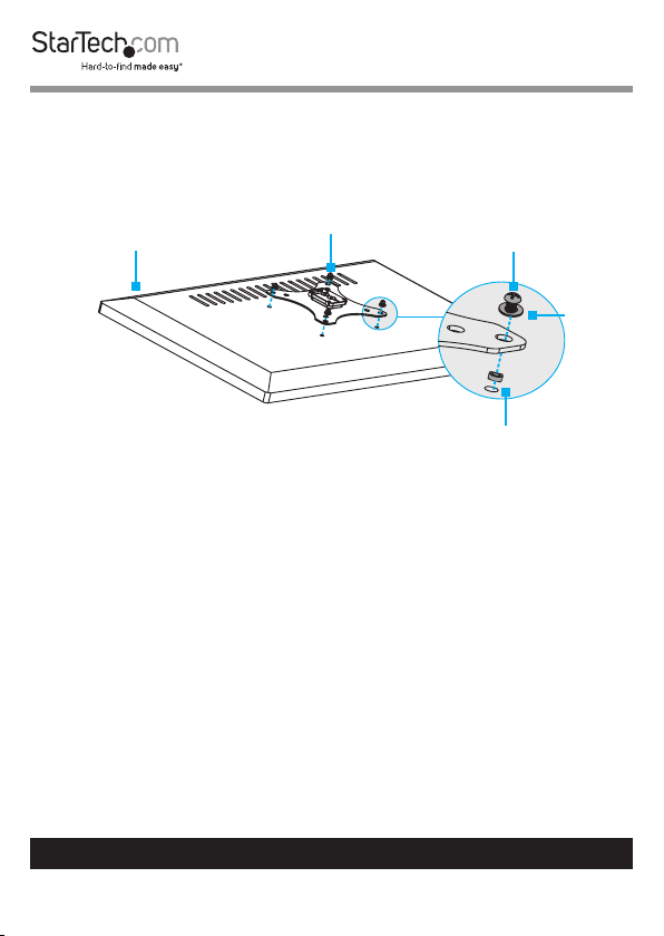
Page 26

6. Place the assembled spring arm and grommet screw over
the grommet hole in your mounting surface.
7. On the underside of the mounting surface, thread the
Grommet Plate (6) through the Grommet Screw so that the
Grommet Plate is ush against the mounting surface.
8. Screw the Grommet Knob (4) onto the Grommet Screw and
turn the Grommet Knob clockwise to tighten it ush against
the Grommet Plate. (Figure 10)
Grommet Screw
Grommet Plate
Grommet Knob
Figure 10
To view manuals, videos, drivers, downloads, technical drawings, and more visit www.startech.com/support
25
Page 27

Attach a Monitor
Warning! Attaching a monitor is a two-person job. Do not
attempt to complete this task by yourself.
To accommodate dierent monitor designs, the Arm Mount
comes with two sets of screws that are dierent lengths and
diameters, and a set of spacers.
To select the appropriate screws for the type of monitor that
you’re using, complete the following:
• Determine whether the back of the monitor is ush or inset.
• Determine the depth of the mounting holes on the monitor.
• Determine the diameter of the mounting holes on the
monitor.
1. Do one of the following:
• If required, place the Spacers (18) over the mounting holes
on the back of your monitor, and position the VESA Monitor
Mount (2) over the spacers. Make sure that you position
the VESA Monitor Mount so that the arrow on the back of
the VESA Monitor Mount is pointed towards the top of the
monitor.
• Position the VESA Monitor Mount (2) over the mounting
holes on the back of your monitor. Make sure that you
position the VESA Monitor Mount so that the arrow on the
back of the VESA Monitor Mount is pointed towards the top
of the monitor.
2. Position the four Washers (17) over the holes on the VESA
Monitor Mount.
To view manuals, videos, drivers, downloads, technical drawings, and more visit www.startech.com/support
26
Page 28
3. Insert the four M4x12 mm Thumbscrews (15) or the four
M5x12 mm Screws (16) through the Washers, the VESA
Monitor Mount, and into the back of the monitor. (gure 11)
VESA Monitor
Top of
Monitor
Mount
M4 Thumbscrew or
M5 Screw
Washer
Figure 11
To view manuals, videos, drivers, downloads, technical drawings, and more visit www.startech.com/support
27
Spacer
Page 29

4. Use a Phillips screwdriver to tighten the screws.
Warning! Do not over-tighten the screws. If you encounter
resistance while you’re tightening the screws, stop tightening.
Failure to do so could result in damage to the monitor.
5. Pull the tab on the Spring Arm (1), and slide the VESA
Monitor Mount and monitor into the mount on the Spring
Arm. (Figure 12)
VESA Monitor
Mount
Spring Arm
Figure 12
To view manuals, videos, drivers, downloads, technical drawings, and more visit www.startech.com/support
28
Page 30

Adjust the Spring Arm
You need to adjust the spring arm in two places.
1. To increase or decrease the tension in the Spring Arm (1),
hold down the Spring Arm so that it is straight, and use
the 6 mm Hex Key (14) to turn the screw in the joint of the
Spring Arm counterclockwise or clockwise. (Figure 13)
6 mm Hex
Key
Figure 13
To view manuals, videos, drivers, downloads, technical drawings, and more visit www.startech.com/support
29
Page 31

2. To change the angle that the monitor is tilted at, use the
6 mm Hex Key to turn the screw in the side of the mount
counterclockwise. When the screw is loose, position the
monitor at the angle that works best for you. Use the 6 mm
Hex Key to turn the screw clockwise to tighten it. (Figure 14)
6 mm Hex
Key
Figure 14
To view manuals, videos, drivers, downloads, technical drawings, and more visit www.startech.com/support
30
Page 32

Tip! If you used the Desk Mount to mount the Arm Mount,
when you’re done adjusting the Arm Mount, you can store the
hex keys in the Hex Key Holder (11) on the side of the L Bracket
(9). (Figure 15)
6 mm Hex
Key
4 mm Hex
Key
Hex Key
Holder
Figure 15
To view manuals, videos, drivers, downloads, technical drawings, and more visit www.startech.com/support
31
Page 33

Routing the Cables
1. On the bottom portion of the Spring Arm (1), slide the Cable
Cover up and away from the Spring Arm. (Figure 16)
Spring
Arm
Cable
Cover
Figure 16
To view manuals, videos, drivers, downloads, technical drawings, and more visit www.startech.com/support
32
Page 34

2. On the upper portion of the Spring Arm, pull the ends of
the Cable Cover away from the Spring Arm, and remove the
Cable Cover from the Spring Arm. (Figure 17)
Spring
Arm
Cable
Cover
Figure 17
To view manuals, videos, drivers, downloads, technical drawings, and more visit www.startech.com/support
33
Page 35

3. Run the cables along the inside of the Cable Cover that you
removed from the upper portion of the Spring Arm.
4. To reattach the Cable Cover, pull out the ends of the Cable
Cover and insert the Tabs on the inside of the Cable Cover
into the holes on the Spring Arm. (Figure 18)
Hole
Spring
Arm
Hole
Tab
Tab
Cable
Cover
Figure 18
To view manuals, videos, drivers, downloads, technical drawings, and more visit www.startech.com/support
34
Page 36

5. Run the cables along the inside of the Cable Cover that you
removed from the bottom portion of the Spring Arm. (Figure
19)
Cable
Cable
Cover
Figure 19
To view manuals, videos, drivers, downloads, technical drawings, and more visit www.startech.com/support
35
Page 37

6. Place the Cable Cover slightly higher than the cavity in the
lower part of the Spring Arm, and slide the Cable Cover
down so that the Hooks on the Cable Cover slide into the
Clips in the Spring Arm. (Figure 20)
Spring
Arm
Cable
Cover
Figure 20
Hook
Hook
To view manuals, videos, drivers, downloads, technical drawings, and more visit www.startech.com/support
36
Page 38

Adjust the Position of the Arm Mount
You can adjust the Arm Mount in the following ways:
180°
180°
360°
270°
To view manuals, videos, drivers, downloads, technical drawings, and more visit www.startech.com/support
+90°
-90°
37
Page 39

Technical Support
StarTech.com’s lifetime technical support is an integral part of our commitment
to provide industry-leading solutions. If you ever need help with your product,
visit www.startech.com/support and access our comprehensive selection of
online tools, documentation, and downloads.
For the latest drivers/software, please visit www.startech.com/downloads
Warranty Information
This product is backed by a two-year warranty.
StarTech.com warrants its products against defects in materials and
workmanship for the periods noted, following the initial date of purchase.
During this period, the products may be returned for repair, or replacement with
equivalent products at our discretion. The warranty covers parts and labor costs
only.
StarTech.com does not warrant its products from defects or damages arising
from misuse, abuse, alteration, or normal wear and tear.
Limitation of Liability
In no event shall the liability of StarTech.com Ltd. and StarTech.com USA LLP (or
their ocers, directors, employees or agents) for any damages (whether direct
or indirect, special, punitive, incidental, consequential, or otherwise), loss of
prots, loss of business, or any pecuniary loss, arising out of or related to the use
of the product exceed the actual price paid for the product.
Some states do not allow the exclusion or limitation of incidental or
consequential damages. If such laws apply, the limitations or exclusions
contained in this statement may not apply to you.
To view manuals, videos, drivers, downloads, technical drawings, and more visit www.startech.com/support
38
38
Page 40

Hard-to-nd made easy. At StarTech.com, that isn’t a slogan.
It’s a promise.
StarTech.com is your one-stop source for every connectivity part you need.
From the latest technology to legacy products — and all the parts that bridge
the old and new — we can help you nd the parts that connect your solutions.
We make it easy to locate the parts, and we quickly deliver them wherever they
need to go. Just talk to one of our tech advisors or visit our website. You’ll be
connected to the products you need in no time.
Visit www.startech.com for complete information on all StarTech.com products
and to access exclusive resources and time-saving tools.
StarTech.com is an ISO 9001 Registered manufacturer of connectivity and
technology parts. StarTech.com was founded in 1985 and has operations in the
United States, Canada, the United Kingdom and Taiwan servicing a worldwide
market.
Reviews
Share your experiences using StarTech.com products, including product
applications and setup, what you love about the products, and areas for
improvement.
StarTech.com
Ltd.
45 Artisans Cres.
London, Ontario
N5V 5E9
Canada
FR: fr.startech.com
DE: de.startech.com
StarTech.com
LLP
2500 Creekside Pkwy.
Lockbourne, Ohio
43137
U.S.A.
ES: es.startech.com
NL: nl.startech.com
StarTech.com Ltd.
Unit B, Pinnacle 15
Gowerton Rd., Brackmills
Northampton
NN4 7BW
United Kingdom
IT: it.startech.com
JP: jp.startech.com
To view manuals, videos, drivers, downloads, technical drawings, and more visit www.startech.com/support
 Loading...