

Page 1
Desk Mount Dual Monitor Arm | Crossbar
Design | Articulating
Actual product may vary from photos
User Manual
SKU#: ARMDUAL2
For the latest information and specications visit
www.startech.com/AMRDUAL2
Manual Revision: 09/23/2019
Page 2

Use of Trademarks, Registered Trademarks, and other
Protected Names and Symbols
This manual may make reference to trademarks, registered trademarks, and
other protected names and/or symbols of third-party companies not related in
any way to StarTech.com. Where they occur these references are for illustrative
purposes only and do not represent an endorsement of a product or service
by StarTech.com, or an endorsement of the product(s) to which this manual
applies by the third-party company in question. Regardless of any direct
acknowledgement elsewhere in the body of this document, StarTech.com
hereby acknowledges that all trademarks, registered trademarks, service marks,
and other protected names and/or symbols contained in this manual and
related documents are the property of their respective holders.
To view manuals, videos, drivers, downloads, technical drawings, and more visit www.startech.com/support
1
Page 3

Warning Statements
• Make sure that you assemble this product according to the instructions.
• Do not exceed the weight capacity of this product. Overloading this product
might result in injury or property damage. This product can support the
following weight: 35.2 lb. (2 x 8 kg).
• This product is intended for indoor use only and should not be used
outdoors.
Varningsmeddelanden
• Se till att du monterar produkten i enlighet med instruktionerna.
• Överskrid inte produktens viktkapacitet. Överbelastning av produkten kan
orsaka skada på person eller egendom. Denna produkt har stöd för följande
vikter: 2 x 8 kg.
• Produkten är endast avsedd för användning inomhus och ska inte användas
utomhus.
Avertissements
• Assemblez ce produit conformément aux instructions.
• Ne dépassez pas la capacité pondérale du produit. Une surcharge du produit
peut entraîner des blessures ou des dommages matériels. Ce produit peut
supporter 2 x 8 kg.
• Ce produit est uniquement destiné à une utilisation en intérieur et ne doit
pas être utilisé à l’extérieur.
Warnhinweise
• Beachten Sie bei der Montage dieses Produkts die Montageanweisungen.
• Überschreiten Sie nicht die Tragkraft dieses Produkts. Ein Überladen dieses
Produkts kann zu Verletzungen oder zur Beschädigung des Produkts führen.
Dieses Produkt ist für folgendes Gewicht geeignet: 2 x 8 kg.
• Dieses Produkt ist nur zum Gebrauch in Innenräumen vorgesehen und sollte
nicht im Freien verwendet werden.
Dichiarazioni di avvertenza
• Assicurarsi di Assemblare il prodotto secondo le istruzioni.
• Non superare la capacità di carico del prodotto. Il sovraccarico del prodotto
potrebbe causare danni o lesioni. Il prodotto è in grado di supportare i
seguenti pesi: 2 x 8 kg.
• Il prodotto è destinato all’uso in ambienti interni. Se ne sconsiglia l’impiego
in ambienti esterni.
To view manuals, videos, drivers, downloads, technical drawings, and more visit www.startech.com/support
2
Page 4

Mensagens de aviso
• Certique-se de que monta este produto de acordo com as instruções.
• Não exceda a capacidade de peso deste produto. Sobrecarregar este produto
pode resultar em ferimentos ou danos de propriedade. Este produto pode
suportar o seguinte peso: 2 x 8 kg.
• Este produto destina-se apenas a uma utilização no interior e não deve ser
utilizado no exterior.
Advertencias de uso
• Asegúrese de ensamblar este producto según las instrucciones.
• Asegúrese de no exceder la capacidad de peso de este producto. La
sobrecarga de este producto puede causar lesiones personales o daños en la
propiedad. Este producto tiene capicidad para el siguiente peso: 2 x 8 kg.
• El uso de este producto es solo para interiores y no debe utilizarse en
exteriores.
Waarschuwingen
• Zorg dat u dit product volgens de instructies in elkaar zet.
• Overschrijd de maximale capaciteit van dit product niet. Overbelasting
van dit product kan letsel of materiële schade veroorzaken. Dit product
ondersteunt het volgende gewicht: 2 x 8 kg.
• Dit product is alleen bedoeld voor binnengebruik en mag niet buiten
worden gebruikt.
注意
• 必ず取扱説明書に従って本製品の組み立てを行って下さい。
• 本製品で定められた最大積載重量を超えないようにして下さい。最大積載重量をオーバーした
場合、怪我をする恐れや器物破損の恐れがあります。
支持 できます。
• 本製品は、室内での使用を想定しています。戸外では使用しないで下さい。
本製品は、モニター1台あたり2x8kgまで
To view manuals, videos, drivers, downloads, technical drawings, and more visit www.startech.com/support
3
Page 5

Table of Contents
Warning Statements ..............................................................................2
Product Diagram ....................................................................................5
Product Dimensions ..............................................................................6
Product Information ..............................................................................7
Package Contents ..................................................................................................................................... 7
Product Specications .............................................................................................................................11
Requirements ............................................................................................................................................. 12
Mounting the Monitor Arm Using the C-Clamp ................................13
Using the Grommet Mount ...................................................................17
Attaching the Monitors (Flush) ............................................................24
Attaching the Monitors (Recessed) .....................................................26
Mounting the Monitors .........................................................................28
Adjusting the Monitors .........................................................................30
Tilt Adjustment .......................................................................................................................................... 30
Micro Adjustments ................................................................................................................................... 31
Routing the Cables .................................................................................33
To view manuals, videos, drivers, downloads, technical drawings, and more visit www.startech.com/support
4
Page 6
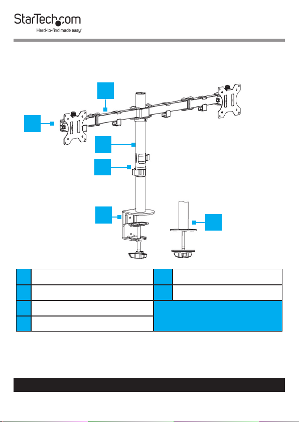
Product Diagram
1
2
3
4
5
1 Swivel Arm Assembly 5 C- Clamp
2 VESA Mount x 2 6 Grommet
3 Pole
4 Cable Management Clips
To view manuals, videos, drivers, downloads, technical drawings, and more visit www.startech.com/support
5
6
Page 7
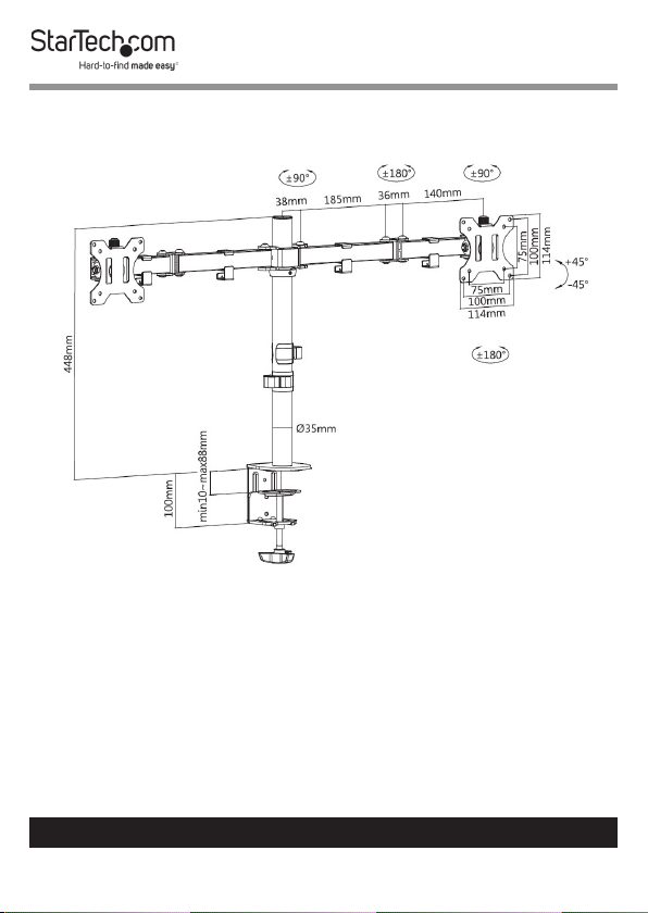
Product Dimensions
To view manuals, videos, drivers, downloads, technical drawings, and more visit www.startech.com/support
6
Page 8
Product Information
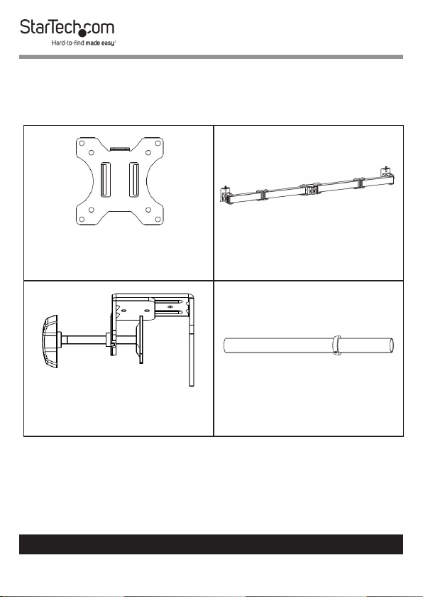
Package Contents
VESA Mounts
Qty: Two
C-Clamp Assembly
Qty: One
To view manuals, videos, drivers, downloads, technical drawings, and more visit www.startech.com/support
Swivel Arm Assembly
Qty: One
Pole
Qty: One
7
Page 9
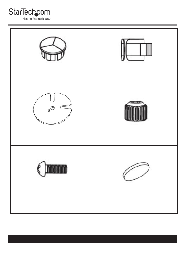
Pole Cap
Qty: One
Cable Management Clip
Qty: Two
Grommet Base Plate
Qty: One
Micro-Adjustment Knobs
Qty: Two
Micro-Adjustment Knob
Screws
Qty: Two
To view manuals, videos, drivers, downloads, technical drawings, and more visit www.startech.com/support
8
Rubber Pads
Qty: Five
Page 10
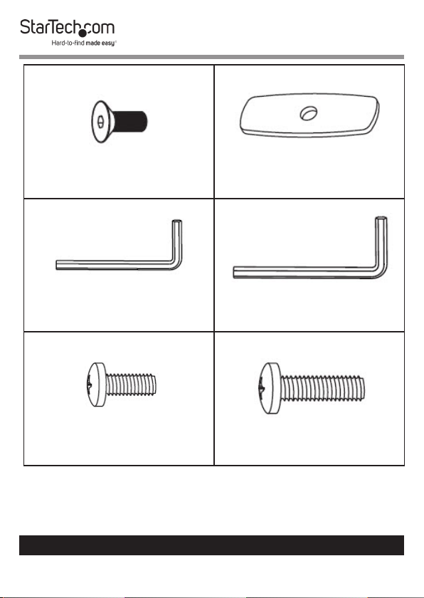
Pole Assembly Screw
Qty: Three
Grommet Plate
Qty: One
4 mm Hex Key
Qty: One
M4 x 12 mm Screws
Qty: Eight
To view manuals, videos, drivers, downloads, technical drawings, and more visit www.startech.com/support
9
6 mm Hex Key
Qty: One
M4 x 16 mm Screws
Qty: Eight
Page 11
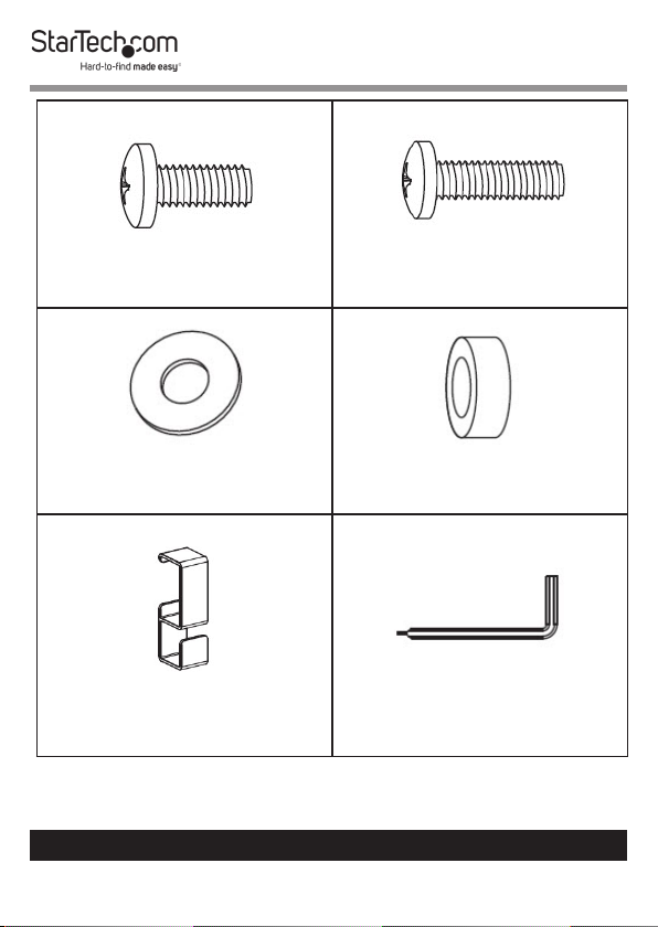
M5 x 12 mm Screws
Qty: Eight
M5 x 16 mm Screws
Qty: Eight
Washers
Qty: Eight
Swivel Arm Cable Clip
Qty: Four
To view manuals, videos, drivers, downloads, technical drawings, and more visit www.startech.com/support
10
Spacers
Qty: Sixteen
3 mm Hex Key
Qty: One
Page 12
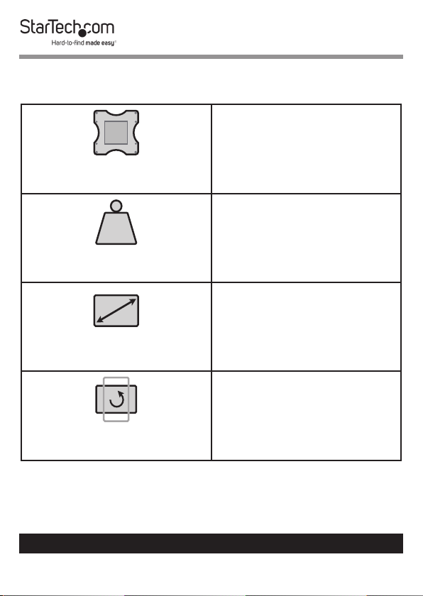
Product Specications
VESA
75 x 75
100 x 100
LB
kg
35.2 lb. (2 x 8 kg)
Total Weight (two monitors)
Max. 32 “
Screen Size
o
360
Rotation
To view manuals, videos, drivers, downloads, technical drawings, and more visit www.startech.com/support
11
Page 13

Tilt
- 450 to +45
0
- 900 to +90
0
Swivel
Requirements
• Phillips Head Screwdriver x 1
• Monitors x 2
• Mounting Surface x 1
To view manuals, videos, drivers, downloads, technical drawings, and more visit www.startech.com/support
12
Page 14

Mounting the Monitor Arm Using the C-Clamp
1. Insert the Pole Cap into the top of the Pole.
Installing the Pole Cap
2. Slide the Cable Management Clips onto of the pole.
- or -
Clip the Cable Management Clip onto the Pole.
Installing Cable Management Clip
3. Align the three Screw Holes on the top of the C-Clamp with
the three Screw Holes on the bottom of the Pole.
4. Insert the three Pole Assembly Screws through the Screw
Holes on the top of the C-Clamp and into the Screw Holes
on the bottom of the Pole.
To view manuals, videos, drivers, downloads, technical drawings, and more visit www.startech.com/support
13
Page 15

5. Using the 4 mm Hex Key, tighten the three Pole Assembly
Screws. Being careful not to over-tighten the Pole Assembly
Screws.
6. Remove the backing from the Rubber Pads (x 5).
7. Apply the adhesive side of the Rubber Pads to the under
side of the top of the C-Clamp.
Attaching the C-Clamp to the Pole
8. While supporting the weight of the Monitor Arm, slide the
C-Clamp over the edge of the Mounting Surface.
9. Using your hand, tighten the Knob until the C-Clamp is
pressed tightly against the Mounting Surface.
To view manuals, videos, drivers, downloads, technical drawings, and more visit www.startech.com/support
14
Page 16

10. Using the 3 mm Hex Key, loosen the Adjustment Screw on
the Collar.
11. Position the Collar at the height you want the Monitors to
sit.
12. Using the 3 mm Hex Key, tighten the Adjustment Screw on
the side of the Collar, securing the Collar to the Pole.
13. Clip the Arm Assembly Clips (x 4) into place along the
Swivel Arm Assembly.
Installing the Arm Assembly Clips
14. Slide the Swivel Arm Assembly over-top of the Pole, until
the Swivel Arm Assembly comes in contact with the Collar.
To view manuals, videos, drivers, downloads, technical drawings, and more visit www.startech.com/support
15
Page 17

Installing the Swivel Arm Assembly
15. While holding the weight of the Swivel Arm Assembly, use
the 6 mm Hex Key to tighten the Adjustment Screw on the
Swivel Arm Assembly to secure the Swivel Arm Assembly
in place.
To view manuals, videos, drivers, downloads, technical drawings, and more visit www.startech.com/support
16
Page 18

Tightening the Swivel Arm
Using the Grommet Mount
1. Insert the Pole Cap into the top of the Pole.
Installing the Pole Cap
To view manuals, videos, drivers, downloads, technical drawings, and more visit www.startech.com/support
17
Page 19

2. Slide the Cable Management Clips onto of the pole.
- or -
Clip the Cable Management Clip onto the Pole.
Installing Cable Management Clip
3. Align the three Screw Holes on the top of the C-Clamp with
the three Screw Holes on the bottom of the Pole.
4. Using a Phillips Head Screw Driver, remove the small screw
attached to the Knob onto the C-Clamp.
Removing the Knob
5. Remove the backing from the Rubber Pads (x 5).
To view manuals, videos, drivers, downloads, technical drawings, and more visit www.startech.com/support
18
Page 20

6. Apply the adhesive side of the Rubber Pads to the side of
the Grommet Base Plate without the protrusion.
7. Align the Protrusion on the Grommet Base Plate with the
Notch on the bottom of the Pole.
Aligning the Grommet Base Plate
8. Insert the Protrusion on the Grommet Base Plate into the
Notch on the bottom of the Pole.
9. While holding the Grommet Base Plate against the bottom
of the Pole, align the center hole on the Grommet Base
Plate with the Grommet Hole in the Mounting Surface.
10. On the under side of the Mounting Surface, align the
Grommet Plate with the Grommet Hole.
11. Insert the Knob through the Grommet Plate and Grommet
Hole and into the Grommet Base Plate and Pole.
To view manuals, videos, drivers, downloads, technical drawings, and more visit www.startech.com/support
19
Page 21

Installing the Grommet
12. Tighten the Knob, until the Grommet Plate and Knob
are pushing tightly against the bottom of the Mounting
Surface.
To view manuals, videos, drivers, downloads, technical drawings, and more visit www.startech.com/support
20
Page 22

Tightening the Knob
13. Using the 3 mm Hex Key, loosen the Adjustment Screw on
the Collar.
14. Position the Collar at the height you want the Monitors to
sit.
15. Using the 3 mm Hex Key, tighten the Adjustment Screw on
the side of the Collar, securing the Collar to the Pole.
16. Clip the Arm Assembly Clips (x 4) into place along the
Swivel Arm Assembly.
To view manuals, videos, drivers, downloads, technical drawings, and more visit www.startech.com/support
21
Page 23

Installing the Arm Assembly Clips
17. Slide the Swivel Arm Assembly over-top of the Pole, until
the Swivel Arm Assembly comes in contact with the Collar.
To view manuals, videos, drivers, downloads, technical drawings, and more visit www.startech.com/support
22
Page 24

Installing the Swivel Arm Assembly
18. While holding the weight of the Swivel Arm Assembly, use
the 6 mm Hex Key to tighten the Adjustment Screw on the
Swivel Arm Assembly to secure the Swivel Arm Assembly
in place.
To view manuals, videos, drivers, downloads, technical drawings, and more visit www.startech.com/support
23
Page 25

Tightening the Swivel Arm
Attaching the Monitors (Flush)
Note: It is recommend that two people are used to mount
the Monitors to the Monitor Mounts.
1. Determine the size and length of screw to use to mount the
Monitors to the Monitor Mounts (M4 x 12 mm or M5 x 12
mm, if appropriate).
To view manuals, videos, drivers, downloads, technical drawings, and more visit www.startech.com/support
24
Page 26

2. Lay the Monitor face down on a at, level surface.
3. Align the Mounting Holes on the VESA Mount with the
Screw Holes on the back of the Monitor, making sure that
the Mounting Flange on the VESA Mount is at the top.
4. Align the Washers (x 4) with the Mounting Holes on the
VESA Mount.
5. Insert the Screws (x 4) through the Washers and Mounting
Holes and into the Screw Holes in the back of the Monitor.
Installing the VESA Mount
6. Using a Phillips Head Screwdriver (sold separately) tighten
the Screws, being careful not to over-tighten.
To view manuals, videos, drivers, downloads, technical drawings, and more visit www.startech.com/support
25
Page 27

Note: Do not over-tighten the Screws. If you encounter resistance while you’re tightening the Screws, stop tightening.
Failure to do so could result in damage to the monitor.
7. Repeat steps 1 - 6 to mount the second Monitor.
Attaching the Monitors (Recessed)
Note: It is recommend that two people are used to mount
the Monitors to the Monitor Mounts.
1. Determine the size and length of screw to use to mount the
Monitors to the Monitor Mounts (M4 x 12 mm or M5 x 12
mm, if appropriate).
2. Lay the Monitor face down on a at, level surface.
3. Align the Spacers (x 4) with the Screw Holes on the back of
the Monitor.
4. Align the Mounting Holes on the VESA Mount with the
Spacers on the back of the Monitor, making sure that the
Mounting Flange on the VESA Mount is at the top.
5. Align the Washers (x 4) with the Mounting Holes on the
VESA Mount.
6. Insert the Screws (x 4) through the Washers and Mounting
Holes and into the Screw Holes in the back of the Monitor.
To view manuals, videos, drivers, downloads, technical drawings, and more visit www.startech.com/support
26
Page 28

Installing the VESA Mount
7. Using a Phillips Head Screwdriver (sold separately) tighten
the Screws, being careful not to over-tighten.
Note: Do not over-tighten the Screws. If you encounter resistance while you’re tightening the Screws, stop tightening.
Failure to do so could result in damage to the monitor.
8. Repeat steps 1 - 6 to mount the second Monitor.
To view manuals, videos, drivers, downloads, technical drawings, and more visit www.startech.com/support
27
Page 29

Mounting the Monitors
1. While supporting the weight of the Monitor, slide the VESA
Mount down onto the Swivel Arm Assembly, aligning the
hole on the Mounting Flange (located on the VESA Mount)
with the Micro-Adjustment Screw Protrusion on the
Monitor Holder.
Installing the Monitors
2. When the Mounting Flange on the VESA Mount is sitting
on the Micro-Adjustment Screw Protrusion, mount
the Micro-Adjustment Knob on the top of the Micro-
Adjustment Screw Protrusion.
3. Insert the Micro-Adjustment Screw through the center
of the Micro-Adjustment Knob and into the Micro-
Adjustment Screw Protrusion.
To view manuals, videos, drivers, downloads, technical drawings, and more visit www.startech.com/support
28
Page 30

4. Using a Phillips Head Screwdriver, tighten the Micro-
Adjustment Screw.
Installing the Micro-Adjustment Knob
5. Adjust the Monitor tilt until it is in the desired position.
6. Using the 6 mm Hex Key, tighten the Adjustment Screw
on the side of the Monitor Holder, securing the Monitor in
place.
To view manuals, videos, drivers, downloads, technical drawings, and more visit www.startech.com/support
29
Page 31

Tightening the Monitor Adjustment Screw
7. Repeat steps 1 - 6 to mount the second Monitor.
Adjusting the Monitors
Tilt Adjustment
1. Using the 6 mm Hex Key, loosen the Adjustment Screw
that is located on the side of the Monitor Mount.
To view manuals, videos, drivers, downloads, technical drawings, and more visit www.startech.com/support
30
Page 32

Adjusting the Monitor Tilt
2. Adjust the tilt of the Monitor.
3. Once the Monitor is in the desired position, tighten the
Adjustment Screw, securing the Monitor in place.
Micro Adjustments
Making micro adjustments will slightly move the monitor up
and down.
• Insert the 6 mm Hex Key into the center- top of the Micro-
Adjustment Knob and turn the Hex Key clockwise or
counter-clockwise to just the Monitor up and down.
To view manuals, videos, drivers, downloads, technical drawings, and more visit www.startech.com/support
31
Page 33

Making Micro Adjustments
To view manuals, videos, drivers, downloads, technical drawings, and more visit www.startech.com/support
32
Page 34

Routing the Cables
• Monitor Cables can be routed along the Swivel Arm
Assembly through the Cable Management Clips along the
Swivel Arm Assembly and down along the Pole through the
Cable Management Clip.
Routing Cables
• Once the Monitor Arm is assembled the Hex Keys can be
placed in the front of the Cable Management Clip on the
Pole.
To view manuals, videos, drivers, downloads, technical drawings, and more visit www.startech.com/support
33
Page 35

Hex Key Holder
To view manuals, videos, drivers, downloads, technical drawings, and more visit www.startech.com/support
34
Page 36

Warranty Information
This product is backed by a ve-year warranty.
For further information on product warranty terms and conditions, please refer
to www.startech.com/warranty.
Limitation of Liability
In no event shall the liability of StarTech.com Ltd. and StarTech.com USA LLP (or
their ocers, directors, employees or agents) for any damages (whether direct
or indirect, special, punitive, incidental, consequential, or otherwise), loss of
prots, loss of business, or any pecuniary loss, arising out of or related to the use
of the product exceed the actual price paid for the product.
Some states do not allow the exclusion or limitation of incidental or
consequential damages. If such laws apply, the limitations or exclusions
contained in this statement may not apply to you.
To view manuals, videos, drivers, downloads, technical drawings, and more visit www.startech.com/support
35
35
Page 37

Hard-to-nd made easy. At StarTech.com, that isn’t a slogan.
It’s a promise.
StarTech.com is your one-stop source for every connectivity part you need.
From the latest technology to legacy products — and all the parts that bridge
the old and new — we can help you nd the parts that connect your solutions.
We make it easy to locate the parts, and we quickly deliver them wherever they
need to go. Just talk to one of our tech advisors or visit our website. You’ll be
connected to the products you need in no time.
Visit www.startech.com for complete information on all StarTech.com products
and to access exclusive resources and time-saving tools.
StarTech.com is an ISO 9001 Registered manufacturer of connectivity and
technology parts. StarTech.com was founded in 1985 and has operations in the
United States, Canada, the United Kingdom and Taiwan servicing a worldwide
market.
Reviews
Share your experiences using StarTech.com products, including product
applications and setup, what you love about the products, and areas for
improvement.
StarTech.com Ltd.
45 Artisans Cres.
London, Ontario
N5V 5E9
Canada
FR: startech.com/fr
DE: startech.com/de
StarTech.com LLP
2500 Creekside Pkwy.
Lockbourne, Ohio
43137
U.S.A.
ES: startech.com/es
NL: startech.com/nl
StarTech.com Ltd.
Unit B, Pinnacle
15 Gowerton Rd.,
Brackmills
Northampton
NN4 7BW
United Kingdom
IT: startech.com/it
JP: startech.com/jp
To view manuals, videos, drivers, downloads, technical drawings, and more visit www.startech.com/support
 Loading...