

Starr Instruments TGD-100 Instructions Manual

TGD-100
Ultrasonic Thickness Gauge
Instruction Manual
VER:3.1

1
Contents
1 INTRODUCTION .................................................................................... 3
1.1 SCOPE OF APPLICATIONS ........................................................................... 3
1.2 PRIMARY THEORY ................................................................................... 3
1.3 MEASURING PRINCIPLE ............................................................................ 3
1.4 APPEARANCE ......................................................................................... 4
1.5 KEYBOARD ............................................................................................ 4
1.6 DISPLAY SYMBOLS ................................................................................... 4
2 PRODUCT SPECIFICATIONS ................................................................... 5
2.1 TECHNOLOGY PARAMETER ........................................................................ 5
2.2 MAIN FUNCTIONS ................................................................................... 5
3 OPERATION .......................................................................................... 6
3.1 PREPARATION FOR MEASUREMENT ............................................................. 6
3.2 ADJUSTING SOUND VELOCITY ..................................................................... 6
3.3 SETTING PROBE FREQUENCY ...................................................................... 7
3.4 MEASUREMENT OF THICKNESS ................................................................... 8
3.5 ZERO CALIBRATION .................................................................................. 8
3.6 MEASUREMENT OF SOUND VELOCITY .......................................................... 9
3.7 SETTING ALARM THICKNESS LIMITS ............................................................ 10
3.8 MENU OPTION ..................................................................................... 10
3.8.1 SYSTEM SETUP .................................................................................. 10
3.8.2 PRINT FUNCTION ............................................................................... 12
3.8.3 MEMORY MANAGE ............................................................................ 14
4 DATA LOGGER OPERATION................................................................. 14
4.1 LOGGING READINGS INTO MEMORY .......................................................... 14
4.2 REVIEWING STORED THICKNESS READINGS .................................................. 15
4.3 CLEARING CURRENT THICKNESS VALUE ...................................................... 15
5. MEASURING TECHNOLOGY ............................................................... 15
5.1 CLEANING SURFACE ............................................................................... 15
5.2 IMPROVING REQUIREMENT ON ROUGHNESS ................................................ 15
5.3 ROUGH MACHINED SURFACE ................................................................... 15
5.4 MEASURING CYLINDRICAL SURFACE ........................................................... 16
5.5 COMPOUND PROFILE ............................................................................. 16

2
5.6 UN-PARALLEL SURFACE .......................................................................... 16
5.7 INFLUENCE OF MATERIAL’S TEMPERATURE .................................................. 16
5.8 MATERIAL WITH LARGE ATTENUATION ....................................................... 16
5.9 REFERENCE TEST PIECE ........................................................................... 17
5.10 SEVERAL MEASURING METHODS ............................................................. 18
5.12 CHANGING PROBE ............................................................................... 19
5.13 MEASURING CASTING .......................................................................... 19
6 PREVENTING ERRORS IN MEASUREMENT ........................................... 20
6.1 ULTRA-THIN MATERIAL .......................................................................... 20
6.2 RUST, CORROSION AND PIT .................................................................... 21
6.3 ERROR IN IDENTIFYING MATERIAL ............................................................ 21
6.4 WEARNESS OF PROBE ............................................................................ 21
6.5 OVERLAPPED MATERIAL AND COMPOUND MATERIAL ................................... 21
6.6 INFLUENCE OF OXIDATION LAYER AT METAL’S SURFACE ................................ 21
6.7 ABNORMAL READOUT OF THICKNESS ........................................................ 22
6.8 UTILIZATION AND SELECTION OF COUPLING AGENT ...................................... 22
7. ATTENTION ....................................................................................... 22
7.1 CLEANING THE TEST PIECE ...................................................................... 22
7.2 CLEANING THE INSTRUMENT’S CASE ......................................................... 23
7.3 PROTECTING THE PROBE ........................................................................ 23
7.4 REPLACING BATTERIES ........................................................................... 23
7.5 ABSOLUTELY AVOID COLLISION AND MOISTURE. ........................................... 23
8. MAINTENANCE .................................................................................. 23
9. OPERATION TO RESTORE THE FACTORY PARAMETERS ...................... 25
10.CONFIGURATION .............................................................................. 26

3
1 Introduction
1.1 Scope of applications
Ultrasonic Thickness Gauge measuring with ultrasonic wave is
applicable for measuring the thickness of any material in which ultrasonic
wave can be transmitted and reflected back from the other face.
The gauge can provide quick and accurate measurement to various
work pieces such as sheets of board and processing parts. Another
important application of the gauge is to monitor various pipes and
pressure vessels in production equipment, and monitor the thinning
degree during using. It can be widely used in petroleum, chemical,
metallurgy, shipping, aerospace, aviation and other fields.
1.2 Primary Theory
The primary theory of measuring thickness with ultrasonic wave is
similar to that of measuring thickness with optical wave. The ultrasonic
wave emitted from the probe reaches the object and transmits in it.
When the ultrasonic wave reaches the bounding surface of the material, it
is reflected back to the probe. The thickness of the material can be
determined by accurately measuring the time of the ultrasonic wave
transmitting in it.
1.3 Measuring Principle
The digital ultrasonic thickness gauge determines the thickness of a part
or structure by accurately measuring the time required for a short
ultrasonic pulse generated by a transducer to travel through the thickness
of the material, reflect from the back or inside surface, and be returned to
the transducer. The measured two-way transit time is divided by two to
account for the down-and-back travel path, and then multiplied by the
velocity of sound in the material.
The result is expressed in the well-known relationship:
Where: H- Thickness of the test piece.
v- Sound Velocity in the material.
t- The measured round trip transit time.
v × t
H =
2

4
1.4 Appearance
1.5 Keyboard
Power ON/OFF ☼ LCD backlight on/off
Sound velocity Save data / Browse data
Calibration standard block of 4.00mm Function selector
Adjusting sound velocity and thickness; key for moving menu cursor
Adjusting sound velocity and thickness; key for moving menu cursor
2-point calibration; to be used together with function keys.
1.6 Display symbols
THICKNESS GUAGE
Ultrasonic

5
2 Product Specifications
2.1 Technology parameter
Display: 128×64 LCD with LED backlight.
Measuring range: 0.75mm~300.0mm (0.03inch~11.8 inch)
Sound Velocity Range: 1000m/s~9999m/s (0.039~0.394in/µs
Display resolution: 0.01mm or 0.1mm (lower than 100.0mm)
0.1mm (more than 99.99mm)
Accuracy: ±(0.5%Thickness +0.02)mm, depends on Materials and
conditions
Units: Metric/Imperial unit selectable.
Lower limit for steel pipes:
5MHz probe: 20mm3.0mm (0.8 0.12 inch)
10MHz probe: 20mm3.0mm (0.6 0.08 inch)
Power Source: 2pcs 1.5V AA size, batteries.100 hours typical operating
time (LED backlight off).
Communication: RS232 serial port
Outline Dimensions: 150mm×74mm×32mm
Weight: 238 g
Four measurements readings per second for single point measurement,
Memory for up to 5 files(up to 100 values for each file) of stored values
2.2 Main Functions
1) Capable of performing measurements on a wide range of material,
including metals, plastic, ceramics, composites, epoxies, glass and other
ultrasonic wave well-conductive materials.
2) Transducer models are available for special application, including for
coarse grain material and high temperature applications.
3) Probe-Zero function, Sound-Velocity, Calibration function.
4) Two-Point Calibration function.
5) Coupling status Indicator showing the coupling status.
6) Battery information indicates the rest capacity of the battery.
7) Auto sleep and auto power off function to conserve battery life.
8) Optional software to process the memory data on the PC.
9) Optional thermal mini-printer to print the measured data via RS232
port.
6
3 Operation
3.1 Preparation for measurement
3.1.1 Insert the probe plug into the socket for the probe on the main
unit,
3.1.2
Press to turn on the instrument.
3.1.3 LCD will Display software editions information about the
instrument. And then display
Latest sound velocity.
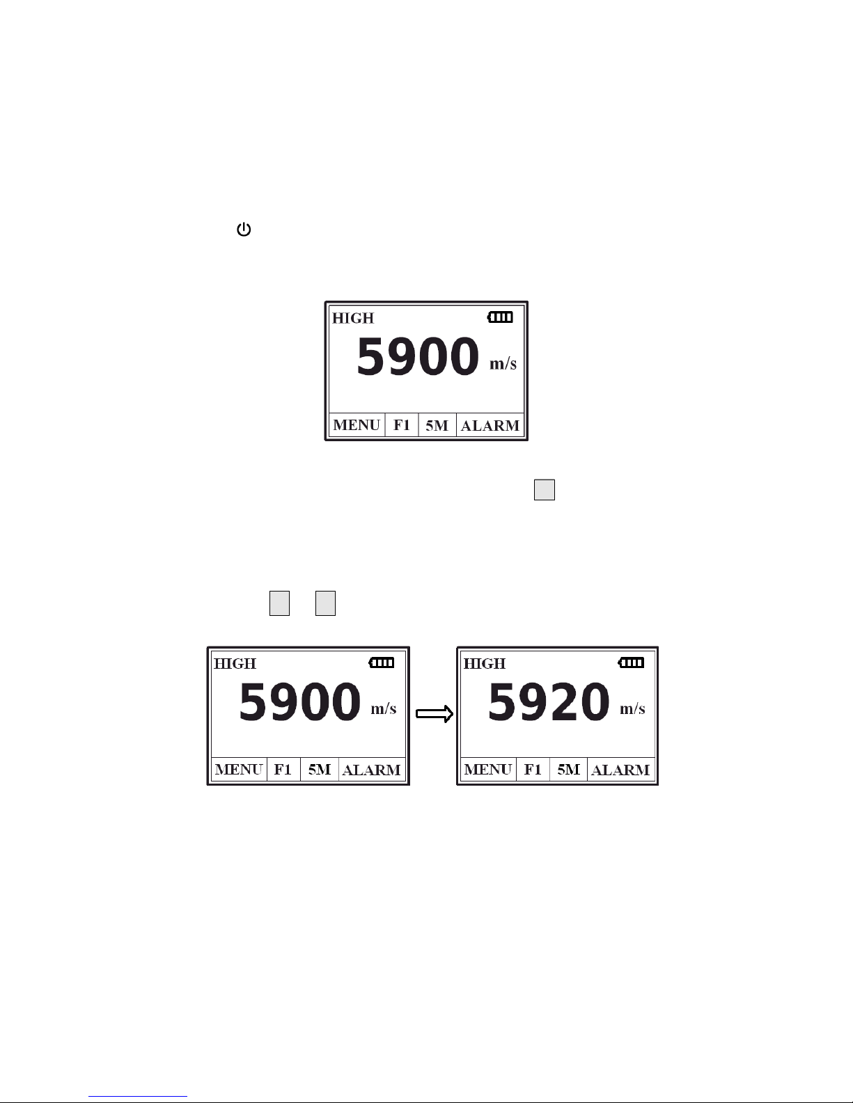
3.2 Adjusting sound velocity
If the current display is thickness, by pressing , you can come into
speed-of-sound state, and it will display content in current sound velocity
memory unit. The sound velocity memory unit will change once every time
when you press the VEL key, it can display 5 sound velocities alternatively. If
you hope to change the contents in the current sound velocity unit, you can
adjust that with or till reach the desired value, and then the value be
saved to memory.
7
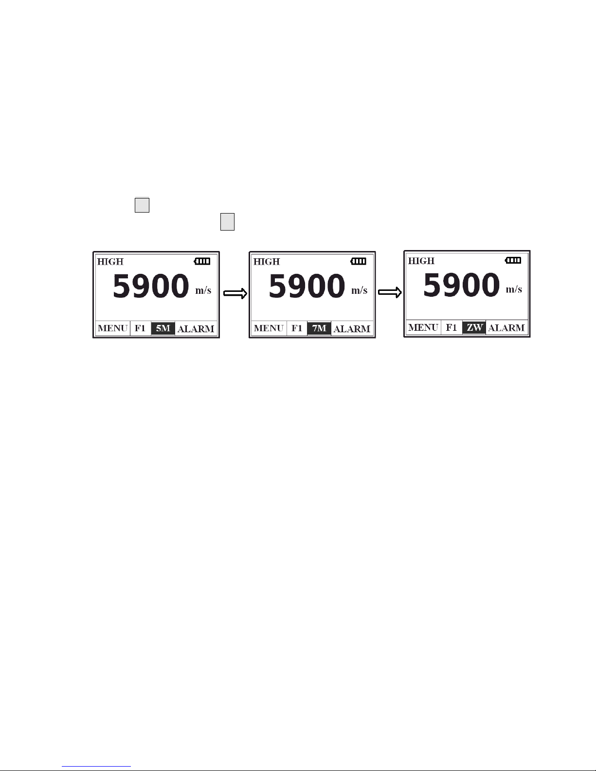
3.3 Setting probe frequency
Press key to move the cursor to the position as that shown in the
following figure. Press to change the frequency setting. LCD will display in
sequence the probe frequency to be set 5M, 7M or ZW.

8
3.4 Measurement of thickness
First, set the sound velocity and then coat the coupling agent at the place
to be measured, couple the probe with the material to be measured, now
you can begin the measurement. The screen will display the thickness of
material to be measured. After you remove the probe, the thickness value
will be maintained, while the coupling indicator will disappear.
Note: when the probe is coupled with the material to be measured, the
instrument will display the coupling indicator; if the indicator flashes or
doesn't appear, it means that the coupling is not so good.
3.5 Zero calibration
Select the correct transducer frequency,The sound velocity adjusted to
5900m / s,While the gain is set to use when measuring the gain,Then the
probe with the case on 4mm standard test block and displayed good
coupling signs,Zero point calibration by the key. Instruments buzzer
about the same time, the screen instructions to complete the
calibration: calibrate zero done, That the calibration is complete, while
calibration data is stored in the instrument, If want to erase the
calibration data, please operate according to memory manage,
If the instrument before the keys are not well coupled with the
standard test block completion instructions or display calibration is not
succeed, the calibration instrument will retain the original value, the
screen display process as shown below:
 Loading...