

Page 1

DOT MATRIX PRINTER
SP200F SERIES
USERS MANUAL
MODE D’EMPLOI
BEDIENUNGSANLEITUNG
MANUALE DI ISTRUZIONI
Page 2

Federal Communications Commission
Radio Frequency Interference
Statement
This equipment has been tested and found to comply with the limits for a Class A digital
device, pursuant to Part 15 of the FCC Rules. These limits are designed to provide
reasonable protection against harmful interference when the equipment is operated in a
commercial environment. This equipment generates, uses and can radiate radio frequency
energy and, if not installed and used in accordance with the instruction manual, may cause
harmful interference to radio communications. Operation of this equipment in a residential
area is likely to cause harmful interference in which case the user will be required to correct
the interference at his own expense.
For compliance with the Federal Noise Interference Standard, this equipment requires a
shielded cable.
This statement will be applied only for the printers marketed in U.S.A.
Statement of
The Canadian Department of Communications
Radio Interference Regulations
This digital apparatus does not exceed the Class A limits for radio noise emissions from
digital apparatus set out in the Radio Interference Regulations of the Canadian Department
of Communications.
Le présent appareil numérique n’émet pas de bruits radioélectriques dépassant les limites
applicables aux appareils numériques de la classe A prescrites dans le Règlement sur le
brouillage radioélectrique édicté par le ministère des Communications du Canada.
The above statement applies only to printers marketed in Canada.
Manufacturer’s Declaration of Conformity
CE
EC Council Directive 89/336/EEC of 3 May 1989
This product, has been designed and manufactured in accordance with the International
Standards EN 50081-1/01.92 and EN 50082-1/01.92, following the provisions of the
Electro Magnetic Compatibility Directive of the European Communities as of May 1989.
EC Council Directive 73/23/EEC and 93/68/EEC of 22 July 1993
This product, has been designed and manufactured in accordance with the International
Standards EN 60950, following the provisions of the Low Voltage Directive of the
European Communities as of July 1993.
The above statement applies only to printers marketed in EU.
Trademark acknowledgments
SP200F Series: Star Micronics Co. Ltd.
VeriFone: VeriFone, Inc.
ESC/POS: Seiko Epson Corporation
Notice
• All rights reserved. Reproduction of any part of this manual in any form whatsoever,
without STAR’s express permission is forbidden.
• The contents of this manual are subject to change without notice.
• All efforts have been made to ensure the accuracy of the contents of this manual at the
time of going to press. However, should any errors be detected, STAR would greatly
appreciate being informed of them.
• The above notwithstanding, STAR can assume no responsibility for any errors in this
manual.
©
Copyright 1994, 1999 Star Micronics Co., LTD.
Page 3

TABLE OF CONTENTS
1. Outline ...............................................................................................................1
2. Unpacking and Installation................................................................................2
2-1. Unpacking ..............................................................................................2
2-2. Locating the printer ................................................................................3
2-3. Handling Care ........................................................................................3
2-4. Maintenance ........................................................................................... 3
3. Parts Identification and Nomenclature ..............................................................4
4. Loading the Ribbon Cartridge and Paper ..........................................................6
4-1. SP210 type .............................................................................................6
4-2. SP240 type .............................................................................................9
4-3. Removing the Paper .............................................................................14
4-4. Connecting the Interface Cable............................................................14
5. Control Panel ...................................................................................................16
5-1. Basic Operation....................................................................................16
5-2. Switch Operation (Combined Switch Operation) ................................17
6. Control Codes ..................................................................................................19
STAR mode..................................................................................................19
6-1. Control Codes Used in Character Setting ............................................19
6-2. Control Codes Used in Print Mode Setting..........................................19
6-3. Control Codes Used in Line Spacing...................................................19
6-4. Control Codes Used for Peripheral Units ............................................20
6-5. Auto Cutter Control .............................................................................20
6-6. Other Control Codes ............................................................................20
Appendix A: Serial Interface...............................................................................87
A-1. Connectors and Signals ........................................................................87
A-2. Interface Connections ..........................................................................88
A-3. Dip Switch Setting ...............................................................................89
A-4. Communication Protcol .......................................................................90
Appendix B: Parallel Interface ............................................................................92
B-1. Interface Specifications........................................................................92
B-2. Interface Timing...................................................................................92
B-3. Connectors and Signals ........................................................................93
B-4. Dip Switch Setting ...............................................................................94
Appendix C: Peripheral Unit Drive Circuit.........................................................95
Appendix D: General Specifications ...................................................................97
Appendix E: Character Font Table....................................................................100
E-1. U.S.A..................................................................................................100
E-2. Europe ................................................................................................102
E-3. International Character Sets ...............................................................104
E-4. VeriFone ............................................................................................105
Page 4

1. Outline
ENGLISH
The SP200 Series Serial Impact Dot Matrix Printer is designed for use with
electronic instruments such as POS, banking equipment, computer peripheral
equipment, etc.
The major features of the SP200 Series are as follows:
1. Bi-directional printing at approx. 2.5 lines/sec.
2. Serial interface or Parallel interface.
3. The data buffer allows the unit to receive print data even during printing.
4. Peripheral unit drive circuit enables control of external devices such as cash
drawers.
SP2 1 2 F D 42 – 120
Voltage
120 : 120VAC
230 : 230VAC
240 : 240VAC
No. of print columns
42 : 42 columns (16 CPI)
Interface
D : Serial interface (RS-232C)
K : Serial interface (RS-422A)
C : Parallel interface
Paper feed
F : Friction paper feed method
Mechanism
2 : Single color, 42 columns (16 CPI)
6 : Two color, 42 columns (16 CPI)
Printer type
1 : Standard type
4 : Auto cutter equipped type
SP200 Series printer
– 1 –
Page 5

2. Unpacking and Installation
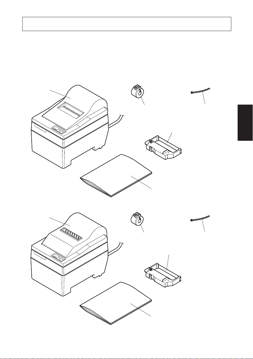
2-1. Unpacking
After unpacking the unit, check that all the necessary accessories are included in
the package.
SP210 type
Printer
ENGLISH
SP240 type
Printer
Ferrite core
(EU only)
User´s manual
Ferrite core
(EU only)
Fastener
(EU only)
Ribbon cartridge
Fastener
(EU only)
Ribbon cartridge
Fig. 2-1 Unpacking
– 2 –
User´s manual
Page 6

2-2. Locating the printer
When you locate your printer, keep the following tips in mind:
ENGLISH
1. Protect your printer from excessive heat such as direct sunlight or heaters, and
keep it away from moisture and dust.
2. Place the printer on a firm, level surface which is fairly vibration-free.
3. A steady power supply that is not subject to power surges should be connected
to the printer.
For example, do not connect it to the same circuit as a large, noise-producing
appliance such as a refrigerator or an air conditioner.
4. Make sure the line voltage is the voltage specified on the printer’s identification plate.
5. To disconnect the printer, the plug has to be disconnected from the wall socket,
which has to be located close to the printer, and easy to access.
2-3. Handling Care
1. Be careful not to drop paper clips, pins or other foreign matter into the unit as
these cause the printer to malfunction.
2. Do not attempt to print when either paper or ribbon cartridge is not located in
the printer, otherwise the print head can be damaged.
3. Do not open the cover while printing.
4. Do not touch the print head immediately after printing as it gets very hot.
5. Use only roll paper that is not glued to the core.
6. When the paper end mark appears on the paper, replace the roll paper before
it runs out.
2-4. Maintenance
Essentially, your printer is a robust piece of equipment, but should be treated with
a modicum of care in order to avoid malfunctions. For example:
1. Keep your printer in a “comfortable” environment. Roughly speaking, if you
feel comfortable, then the environment is suitable for your printer.
2. Do not subject the printer to physical shocks or excessive vibration.
3. Avoid over-dusty environments. Dust is the enemy of all precision mechanical devices.
4. To clean the exterior of the printer, use a cloth barely dampened with either
water with a little detergent or a little alcohol, but do not allow any liquid to
fall inside the printer.
5. The interior of the printer may be cleaned with a small cleaner or a compressed-air aerosol (sold for this purpose). When performing this operation,
be sure not to bend or damage any cable connections or electronic components.
– 3 –
Page 7

SP210 type
3. Parts Identification and Nomenclature
Cover
Protects the printer from
dust and reduces noise.
Do not open the cover
while printing.
AC power cord
Plugs into an outlet of
the specified voltage.
Shape of AC power plug
will vary according to
destinations.
ENGLISH
Control panel
Features two control
switches and two
indicators to indicate
printer status.
Interface connector
Connects the printer
with host computer.
Peripheral unit drive circuit connector
Connects to peripheral units such
as cash drawers, etc.
Do not connect this to a telephone.
Fig. 3-1 External view of the printer (SP210 type)
– 4 –
Page 8

SP240 type
ENGLISH
Cover
Protects the printer from
dust and reduces noise.
Do not open the cover
while printing.
Control panel
Features two control
switches and two
indicators to indicate
printer status.
AC power cord
Plugs into an outlet of
the specified voltage.
Shape of AC power plug
will vary according to
destinations.
Interface connector
Connects the printer
with host computer.
Peripheral unit drive circuit connector
Connects to peripheral units such
as cash drawers, etc.
Do not connect this to a telephone.
Fig. 3-2 External view of the printer (SP240 type)
– 5 –
Page 9

4. Loading the Ribbon Cartridge and Paper
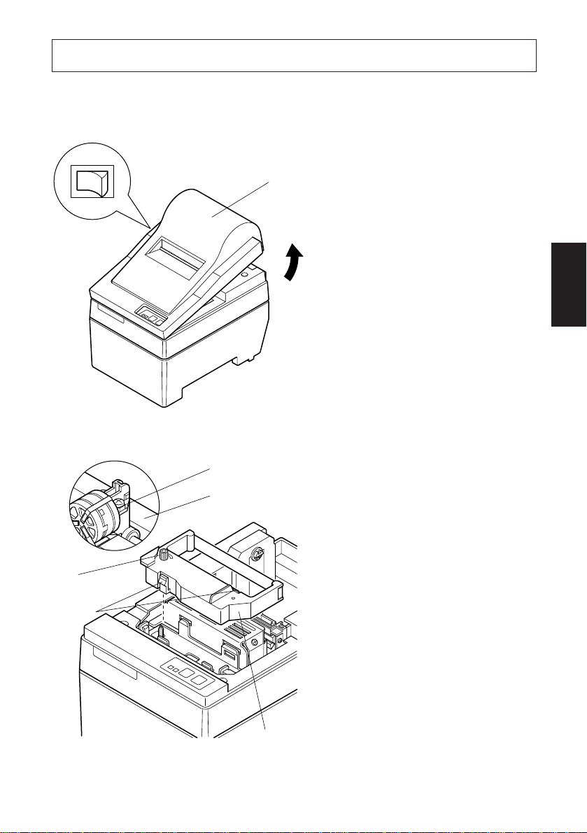
4-1. SP210 type
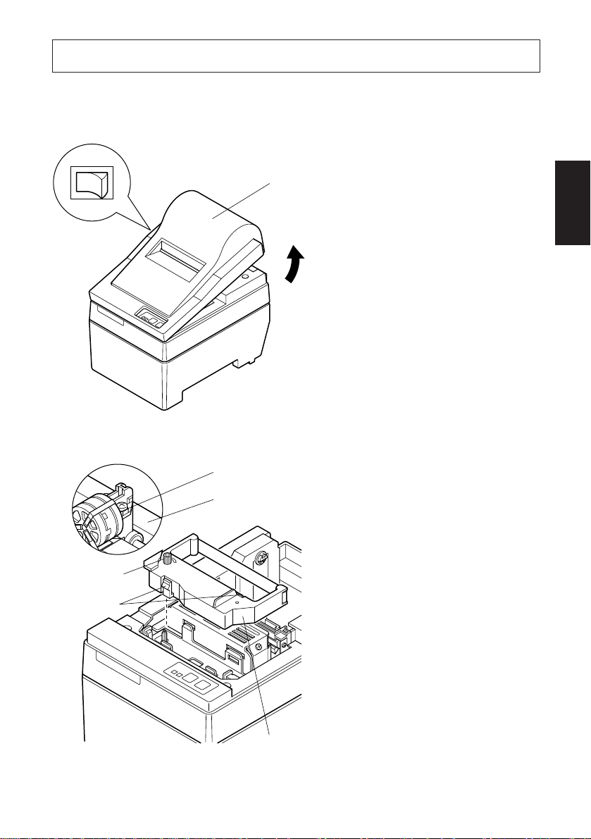
4-1-1.Loading the Ribbon Cartridge
Cover
Power off
1 Turn off power to the printer.
2 Lift the cover up approx. 3 cm.
Hold the cover tilted at this angle, then pull it toward you to
remove it.
3 Place the ribbon cartridge in the
direction shown in Fig. 4-2 and
press it down to load it. If loading
of the ribbon cartridge is not satisfactory, press down the cartridge while rotating the ribbon
feed knob in the direction of the
arrow.
ENGLISH
Fig. 4-1 Removing the cover
Print head
Ink ribbon
Ribbon feed
knob
Notched
part
Ribbon cartridge
Fig. 4-2 Loading the ribbon cartridge
4 Turn the ribbon feed knob of the
ribbon cartridge in the direction
of the arrow to remove slack in
the ribbon.
5 Mount the cover by reversing the
procedure outlined in step 2
above.
– 6 –
Page 10

ENGLISH
A
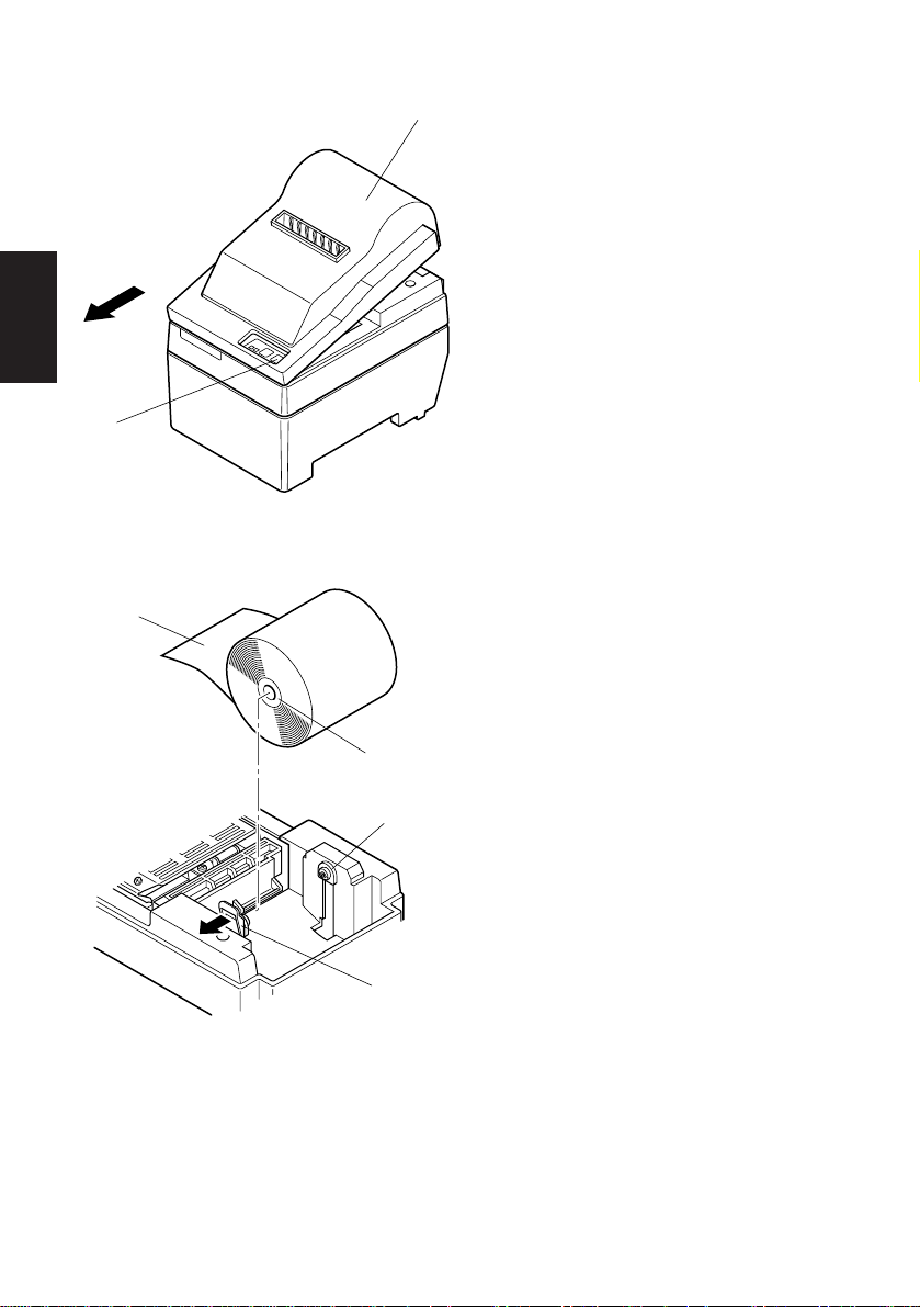
4-1-2.Loading the Paper
Note: When removing the ribbon car-
tridge, raise the A section and
then remove it by holding the B
section as shown in Fig. 4-3.
B
Fig. 4-3
FEED
switch
Fig. 4-4 Removing the cover
Cover
1 Lift the cover up approx. 3cm. Hold
the cover tilted at this angle, then
pull it toward you to remove it.
– 7 –
Page 11

Roll paper
Fig. 4-5 Loading the paper
Positioning rib
Core
Axis
Paper roll holder
Cover
Roll paper
2 Cut off the front edge of the roll
paper perpendicularly.
3 Confirm that the power of the printer
is turned on.
4 While observing the direction of the
roll paper, insert the top end of the
paper beneath the paper guide as far as
it will go. If the roll paper is installed,
the top end of the paper automatically
comes out from the paper exit.
5 Move the paper roll holder in the
direction of the arrow, and insert the
roll so that the holes in the core align
with the axes of the paper roll holder.
Release the paper roll holder to secure the paper.
6 If the paper roll core has not been
properly aligned with the paper roll
holder, the cover cannot to properly
seated until the paper position is
corrected.
7 Press the FEED (paper feed) switch to
feed the paper approximately 10cm.
8 Insert the top edge of the paper into
the tear bar slot, then mount the cover
by reversing the procedure for removing the cover in step 1 above.
Note: When the paper end mark ap-
pears on the paper, replace the
roll paper before it runs out.
ENGLISH
Paper roll holder
Fig. 4-6
– 8 –
Tear bar
FEED switch
Fig. 4-7
Page 12

4-2. SP240 type
r
4-2-1.Loading the Ribbon Cartridge
ENGLISH
Power off
Fig. 4-8 Removing the cover
Auto cutter
Cove
1 Turn off power to the printer.
2 Lift the cover up approx. 3 cm.
Hold the cover tilted at this angle, then pull it toward you to
remove it.
3 Lift up the auto cutter and put it in
a vertical position, as shown in
Fig. 4-9.
Fig. 4-9 Raise the auto cutter
– 9 –
Page 13

Ribbon feed
knob
Notched
part
Print head
Ink ribbon
Auto cutter
4 Place the ribbon cartridge in the
direction shown in Fig. 4-10 and
press it down to load it. If loading
of the ribbon cartridge is not satisfactory, press down the cartridge while rotating the ribbon
feed knob in the direction of the
arrow.
5 Turn the ribbon feed knob of the
ribbon cartridge in the direction
of the arrow to remove slack in
the ribbon.
ENGLISH
Ribbon cartridge
Fig. 4-10 Loading the ribbon cartridge
A
B
Fig. 4-11
6 Close the Auto Cutter.
7 Mount the cover by reversing the
procedure outlined in step 2
above.
Note: When removing the rib-
bon cartridge, raise the A
section and then remove
it by holding the B section
as shown in Fig. 4-11.
– 10 –
Page 14

4-2-2.Loading the Paper
ENGLISH
FEED
switch
Fig. 4-12 Removing the cover
Cover
1 Lift the cover up approx. 3cm. Hold
the cover tilted at this angle, then
pull it toward you to remove it.
Roll paper
Fig. 4-13 Loading the paper
Core
Axis
Paper roll holder
2 Cut off the front edge of the roll
paper perpendicularly.
3 Confirm that the power of the printer
is turned on.
4 While observing the direction of the
roll paper, insert the top end of the
paper beneath the paper guide as far as
it will go. If the roll paper is installed,
the top end of the paper automatically
comes out from the paper exit. After
2cm of paper are fed out, the paper
is automatically cut off.
5 Move the paper roll holder in the
direction of the arrow, and insert the
roll so that the holes in the core align
with the axes of the paper roll holder.
Release the paper roll holder to secure the paper.
6 If the paper roll core has not been
properly aligned with the paper roll
holder, the cover cannot to properly
seated until the paper position is
corrected.
– 11 –
Page 15

7 Press the FEED (paper feed) switch
to feed the paper approximately
10cm.
Positioning rib
Paper roll holder
Cover
Roll paper
Fig. 4-14
Auto
Paper
insertion
slit
cutter
Fig. 4-15 Insertion of the paper into
the auto cutter
ENGLISH
8 Insert the tip of the roll paper in the
auto cutter paper slit.
• When using copying paper, insert
only the original (the upper paper)
into the slit of the auto cutter. Insert
the paper which is to be copied (the
lower paper) between the platen and
the auto cutter.
– 12 –
Page 16

ENGLISH
Paper insertion
slit
Auto cutter
Upper paper
Upper
paper
Print head
Lower paper
Fig. 4-16 Insertion of the paper into the auto cutter
(When using copying paper)
Paper
outlet
Auto cutter
Fig. 4-17 Paper outlet of the front
cover
Paper insertion
slit
Platen
9 Pull on the edge of the paper to
0 Insert the paper through the paper
Lower paper
Print head
Platen
remove any slack and then lower the
auto cutter.
outlet and then replace the cover by
reversing the removal steps.
Note: When the paper end mark ap-
pears on the paper, replace the
roll paper before it runs out.
– 13 –
FEED switch
Fig. 4-18
Page 17

4-3. Removing the Paper
Remove the cover, then cut off the paper near the rear of the paper guide and press
the FEED switch to feed out the paper remaining in the unit.
When the paper runs out, the POWER lamp will blink.
Note 1. Remove the paper remaining in the printer by pressing the FEED
switch.
2. When the paper end mark appears on the paper, replace the roll
paper before it runs out.
3. When removing the core of the roll paper, open the roll paper
holder.
4-4. Connecting the Interface Cable
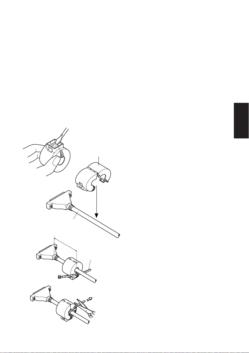
4-4-1.Ferrite core installation (EU only)
1 Affix the ferrite core onto the serial/
parallel interface cable as shown in
Ferrite core
Interface cable
the illustration.
If a ferrite core is not open, use a
screw driver to pry it apart, taking
care not to damage the core or lock.
2 Pass fastener through ferrite core.
3 Pass fastener around cable and lock
it.
Cut off excess with scissors.
Attach the ferrite core only to the
cables of printers sold in the EU.
ENGLISH
5cm
maximum
Fig. 4-19
Fastener
Pull and cut
– 14 –
Page 18

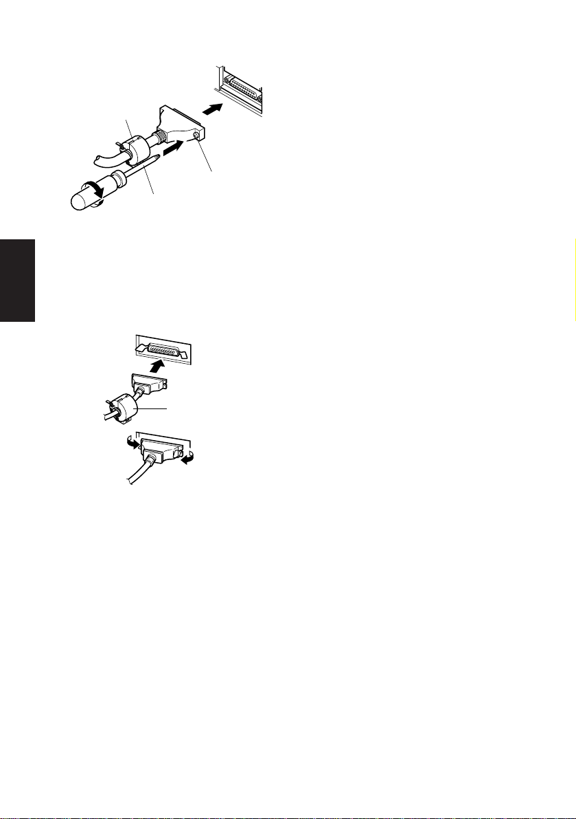
4-4-2.Serial Interface Cable
ENGLISH
Ferrite core
(EU only)
Screwdriver
Fig. 4-20 Connecting the interface
cable
4-4-3.Parallel Interface Cable
Fig. 4-21 Connecting the parallel
interface cable
Screws
Ferrite core
(EU only)
1 Turn off power to both the host
computer and the printer.
2 Insert the connector at one end of
the interface cable into the connector on the printer and the other connector into the connector for the
host computer.
3 Next, fasten the right and left screws
for the respective interface connectors to fix them in place on the
connectors.
1 Turn off power to both the host
computer and the printer.
2 Insert one terminal of the interface
cable into the printer’s connector,
as shown in the diagram, and fasten
it there with the clasp.
3 Insert the other terminal of interface
cable into the host computer’s connector, and again fasten it with the
clasp.
– 15 –
Page 19

5-1. Basic Operation
5. Control Panel
ON LINEPOWER FEED
1 ON LINE switch
Switches the printer between ON
LINE and OFF LINE. ON LINE
and OFF LINE switching is possible only when paper is loaded in the
printer.
3 4 1 2
2 FEED switch
• When this switch is pressed and
Fig. 5-1 Control panel
then released within 0.5 sec., the
paper feeds on line.
• When this switch is held depressed
for more than 0.5 sec., the paper
feeds continuously.
(The above paper feed operation is
possible for both ON LINE and OFF
LINE modes.)
3 POWER lamp (green LED)
• Lights when the power to the printer is on.
• Flashes when paper is out, mechanical error occurs, when there is an alarm due
to head temperature detection, or when a CPU error has occurred.
• If the paper is out, load new paper and press the ON LINE switch.
• When the POWER lamp flashes due to occurrence of a mechanical error, turn
off the power and remove the cause of a mechanical error and then turn on the
power again to reset the printer.
• If the POWER lamp flashes due to the alarm of the head temperature detection,
the printer will be set automatically when the head temperature becomes low.
4 ON LINE lamp (green LED)
LED lit: Printer is ON LINE
LED off: Printer is OFF LINE
LED flashes: CPU error
ENGLISH
When the POWER lamp and ON LINE lamp light simultaneously, a CPU
error has occurred.
– 16 –
Page 20

5-2. Switch Operation (Combined Switch Operation)
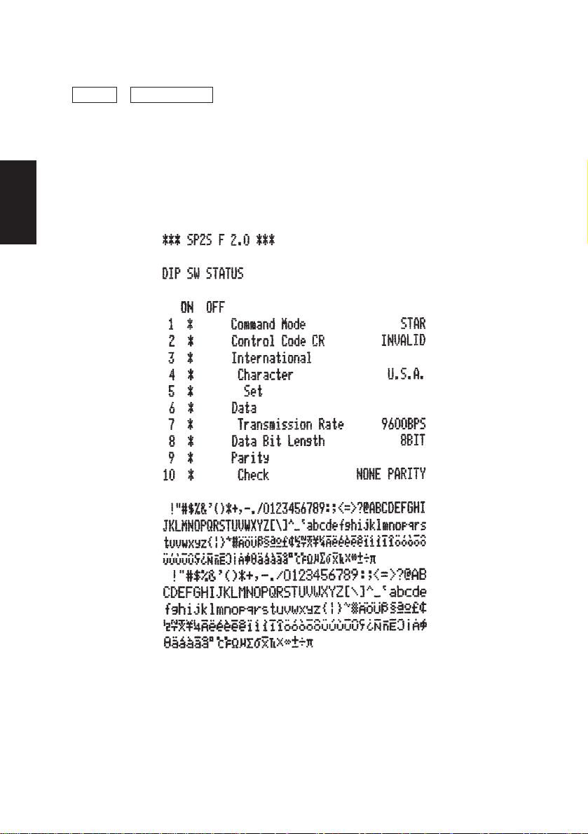
1 <SELF PRINTING>
ENGLISH
FEED + POWER ON (Turn the power on while holding the FEED switch
depressed.)
Self-printing will be performed according to the VER. NO., DIP switch
settings and character order. When the FEED switch is held continuously or
when the FEED switch is depressed at the time of the end of self-printing, only
the characters will be printed out repeatedly.
Fig. 5-2 Self printing sample (when using serial interface RS-232C printer)
– 17 –
Page 21

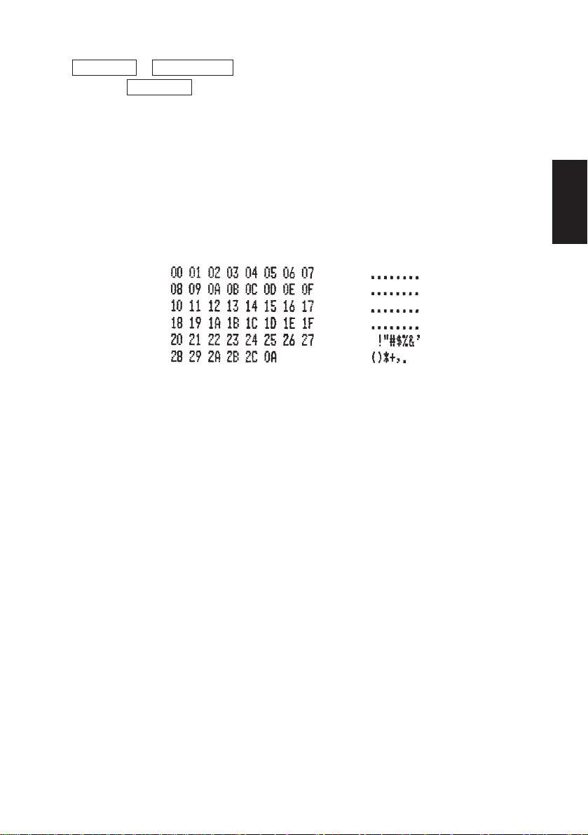
2 <Hexadecimal dump mode>
ON LINE + POWER ON (Turn the power on while holding the ON LINE
switch depressed.)
Each of the signals sent from the computer to the printer will be printed out in
hexadecimal code.
This function allows you to check if a control code sent to the printer by the
program being used is correct or not. The last line is not printed if its data is
less than one full line. However, if the ON LINE switch is pressed to set the
off line mode, the last line will be printed. To turn off the mode, it is necessary
to turn off the printer completely.
Fig. 5-3 Hexadecimal dump printing sample
ENGLISH
– 18 –
Page 22

6. Control Codes
ENGLISH
STAR mode
6-1. Control Codes Used in Character Setting
Control codes Hexadecimal codes Function
<ESC> “R” n 1B 52 n Select international character set. Default is accord-
ing to the dip switch settings 3, 4 and 5.
<ESC> “M” 1B 4D Select 7 × 7 (Half dots) character size (Default
setting)
<ESC> “P” 1B 50 Select 9 × 7 (Half dots) character size
<SO> 0E Select expanded character mode
<SI> 0F Cancel expanded character mode
(Default setting)
<DC4> 14 Cancel expanded character mode
(Default setting)
<ESC> “W” “1” 1B 57 31 Select expanded character mode
<ESC> “W” <1> 1B 57 01
<ESC> “W” “0” 1B 57 30 Cancel expanded character mode
<ESC> “W” <0> 1B 57 00 (Default setting)
6-2. Control Codes Used in Print Mode Setting
Control codes Hexadecimal codes Function
<ESC> “4” 1B 34 Red color print selection (enable for SP216/246)
<ESC> “5” 1B 35 Red color print deselection (enable for SP216/246)
(Default setting)
<ESC> “E” 1B 45 Emphasized print mode selection
<ESC> “F” 1B 46 Emphasized print mode deselection (Default set-
ting)
6-3. Control Codes Used in Line Spacing
Control codes Hexadecimal codes Function
<LF> 0A Line feed
<CR> 0D Line feed (same as LF)
<ESC> “a” n 1B 61 n Feed paper n lines
– 19 –
Page 23

6-4. Control Codes Used for Peripheral Units
Control codes Hexadecimal codes Function
<ESC> <BEL> n1 n2 1B 07 n1 n2 Adjust drive pulse width for peripheral unit (Default
setting)
<BEL> 07 Deferred drive command “A” for peripheral unit 1
<FS> 1C Immediate drive command “B” for peripheral unit 1
6-5. Auto Cutter Control (SP240 type only)
Control codes Hexadecimal codes Function
<ESC> “d” “0” 1B 64 30 Full-cut command to the auto cutter
<ESC> “d” <0> 1B 64 00
<ESC> “d” “1” 1B 64 31 Partial-cut command to the auto cutter
<ESC> “d” <1> 1B 64 01
<ESC> “d” “2” 1B 64 32 Full-cut command to the auto cutter
<ESC> “d” <2> 1B 64 02 after paper feed
<ESC> “d” “3” 1B 64 33 Partial-cut command to the auto cutter after paper
<ESC> “d” <3> 1B 64 03 feed
6-6. Other Control Codes
Control codes Hexadecimal codes Function
<CAN> 18 Cancel print data in buffer
<ENQ> *
<DC1> *
<DC3> *
<ESC> “@” 1B 40 Initialize printer
<ESC> “e” “0” 1B 65 30 ON LINE/FEED switch valid
<ESC> “e” <0> 1B 65 00 (Default setting)
<ESC> “e” “1” 1B 65 31 ON LINE/FEED switch invalid
<ESC> “e” <1> 1B 65 01
<ESC> “f” “0” 1B 66 30 ON LINE switch valid
<ESC> “f” <0> 1B 66 00 (Default setting)
<ESC> “f” “1” 1B 66 31 ON LINE switch invalid
<ESC> “f” <1> 1B 66 01
1 05 Enquiry
1 11 Set select mode
1 13 Deselect printer
ENGLISH
*1: Valid for the RS-422A only.
– 20 –
Page 24

ENGLISH
– 21 –
Page 25

TABLE DES MATIERES
1. Introduction .....................................................................................................23
2. Déballage et Inspection ...................................................................................24
2-1. Déballage .............................................................................................24
2-2. Emplacement de l’imprimante .............................................................25
2-3. Précautions de manipulation ................................................................25
2-4. Entretien ...............................................................................................25
3. Identification des Pièces et Nomenclature ......................................................26
4. Installation d’une cartouche à ruban et chargement du papier ........................28
4-1. Modèle SP210 ......................................................................................28
4-2. Modèle SP240 ......................................................................................31
4-3. Enlèvement d’un rouleau de papier .....................................................36
4-4. Connexion du câble d’interface ...........................................................36
5. Panneau de Commande ...................................................................................38
5-1. Fonctionnement de base.......................................................................38
5-2. Utilisation des touches (Utilisation combinée des touches) ................39
6. Codes de contrôle ............................................................................................41
Mode STAR .................................................................................................41
6-1. Commandes utilisées pour le réglage des caractères ...........................41
6-2. Commandes utilisées pour le réglage du mode d’impression..............41
6-3. Commandes utilisées pour l’espacement des lignes ............................41
6-4. Commandes utilisées pour le pilotage des appareils périphériques.....42
6-5. Commandes de pilotage de l’unité de découpage automatique
(Modèle SP240 seulement) ..................................................................42
6-6. Autres commandes ...............................................................................42
APPENDICE .......................................................................................................87
FRANÇAIS
L’appendice n’est pas traduit.
– 22 –
Page 26

1. Introduction
L’imprimante série à impact et matrice de points est conçue pour une utilisation
avec des instruments électroniques tels que des terminaux points de vente, du
matériel bancaire, du matériel périphérique pour ordinateurs, etc.
Les caractéristiques principales des modèles de la série SP200 sont les suivantes:
FRANÇAIS
1. Impression bi-directionnelle à 2,5 lignes/sec. environ.
2. Interface série ou parallèle.
3. Tampon de données permettant à l’appareil de recevoir des données d’impression même pendant le travail d’impression.
4. Circuit de contrôle d’appareils périphériques permettant la commande de
dispositifs extérieurs tels que des tiroirs-caisses.
SP2 1 2 F D 42 – 120
Tension
120 : 120V CA
230 : 230V CA
240 : 240V CA
Nombre de colonnes d’impression
42 : 42 colonnes (16 ccp)
Interface
D : Interface série (RS-232C)
K : Interface série (RS-422A)
C : Interface parallèle
Alimentation de papier
F:
Alimentation de papier par friction
Mécanisme
2:
Une couleur, 42 colonnes (16 ccp)
6:
Deux couleurs, 42 colonnes (16 ccp)
Type d’imprimante
1 : Type standard
4 : Type avec unité de découpage
automatique
Imprimante de la série SP200
– 23 –
Page 27

2. Déballage et Inspection
2-1. Déballage
Après avoir déballé l’appareil, vérifiez si tous les accessoires nécessaires se
trouvent dans la boîte.
Modèle SP210
Imprimante
Tore de ferrite
(UE seulement)
Cartouche à ruban
Mode d’emploi
Attache
(UE seulement)
FRANÇAIS
Modèle SP240
Imprimante
Tore de ferrite
(UE seulement)
Fig. 2-1 Déballage
– 24 –
Attache
(UE seulement)
Cartouche à ruban
Mode d’emploi
Page 28

2-2. Emplacement de l’imprimante
Pour installer correctement l’imprimante, gardez à l’esprit les conseils suivants:
1. Mettez l’imprimante à l’abri de températures excessivement élevées comme en plein
soleil ou à proximité d’un appareil de chauffage, et à l’abri de l’humidité et de la
poussière.
2. Installez l’imprimante sur une surface stable et de niveau sur laquelle l’imprimante
FRANÇAIS
ne sera pas soumise à des vibrations.
3. Veillez à ce que l’imprimante soit branchée sur une source secteur stable.
Par exemple, ne pas brancher l’imprimante sur la prise secteur d’un circuit alimentant
déjà un appareil électroménager gros consommateur de courant et producteur de
parasites, tel qu’un réfrigérateur ou un climatiseur.
4. Veillez à ce que la tension du secteur corresponde bien à la tension spécifiée sur la
plaque d’identification de l’imprimante.
5. Pour débrancher l’imprimante, la fiche doit être débranchée de la prise murale, et
celle-ci doit être située à proximité de l’imprimante et facile d’accès.
2-3. Précautions de manipulation
1. Faites attention à ne pas laisser tomber de trombones, punaises ou autres objets dans
l’imprimante. Un dysfonctionnement pourrait en résulter.
2. Ne pas essayer d’imprimer quand il n’y a pas de papier ou de cartouche à ruban dans
l’imprimante. La tête d’impression pourrait être endommagée.
3. Ne pas ouvrir le capot pendant l’impression.
4. Ne pas toucher la tête d’impression immédiatement après un travail d’impression car
elle devient très chaude.
5. Utilisez seulement un rouleau de papier dont l’extrémité n’est pas collée au tube
central.
6. Quand le repère de fin de papier apparaît sur le papier, remplacez le rouleau de papier
avant qu’il soit terminé.
2-4. Entretien
Avant tout, cette imprimante est un appareil robuste, mais un minimum de précautions
sont à prendre pour éviter les dysfonctionnements. Par exemple:
1. Laissez l’imprimante dans un environnement “confortable”. En gros, si vous êtes à
l’aise, l’environnement sera acceptable pour l’imprimante.
2. Ne pas soumettre l’imprimante à des chocs ou à des vibrations excessives.
3. Évitez les environnements excessivement poussiéreux. La poussière est l’ennemi de
tous les appareils mécaniques de précision.
4. Pour nettoyer l’extérieur de l’imprimante, utilisez un chiffon légèrement imbibé
d’eau ou d’alcool, mais ne laissez aucun liquide pénétrer à l’intérieur de l’imprimante.
5. L’intérieur de l’imprimante peut être nettoyé avec une petite brosse de nettoyage ou
un aérosol à air comprimé (vendu à cet effet). Pendant cette opération, veillez à ne pas
plier ni endommager les connexions ou les composants électroniques.
– 25 –
Page 29

3. Identification des Pièces et Nomenclature
Modèle SP210
Capot
Protège l’imprimante de la
poussière et réduit le bruit.
Ne pas ouvrir le capot
pendant l’impression.
FRANÇAIS
Panneau de commande
Comprend deux
commutateurs de
commande et trois témoins
indiquant le statut de
l’imprimante.
Cordon d’alimentation secteur
A brancher sur la sortie
correspondant à la tension
spécifiée. La présentation
de la fiche du cordon
d’alimentation secteur
varie selon les pays.
Connecteur d’interface
Ce connecteur vous
permet de raccorder
l’imprimante à
l’ordinateur hôte.
Connecteur de pilotage d’appareils périphériques
Ce connecteur vous permet de
raccorder l’imprimante à des appareils
périphériques tels que des tiroirs-caisses, etc.
Ne pas raccorder à un téléphone.
Fig. 3-1 Vue externe de l’imprimante (Modèle SP210)
– 26 –
Page 30

Modèle SP240
FRANÇAIS
Capot
Protège l’imprimante de la
poussière et réduit le bruit.
Ne pas ouvrir le capot
pendant l’impression.
Panneau de commande
Comprend deux
commutateurs de
commande et
deux témoins
indiquant le statut
de l’imprimante.
Cordon d’alimentation secteur
A brancher sur la sortie
correspondant à la tension
spécifiée. La présentation
de la fiche du cordon
d’alimentation secteur varie
selon les pays.
Connecteur d’interface
Ce connecteur vous
permet de raccorder
l’imprimante à
l’ordinateur hôte.
Connecteur de pilotage d’appareils périphériques
Ce connecteur vous permet de
raccorder l’imprimante à des appareils
périphériques tels que des
tiroirs-caisses, etc.
Ne pas raccorder à un téléphone.
Fig. 3-2 Vue externe de l’imprimante (Modèle SP240)
– 27 –
Page 31
4. Installation d’une cartouche à ruban et chargement du papier
4-1. Modèle SP210
4-1-1. Installation d’une cartouche à ruban
1 Mettez l’imprimante hors tension.
Capot
Hors tension
Fig. 4-1. Dépose du capot
2 Soulevez le capot d’environ 3
cm. Tout en tenant le couvercle
incliné à cet angle, tirez-le vers
vous pour l’enlever.
3 Mettez la cartouche à ruban en
place dans le sens indiqué dans la
figure 4-2 et appuyez légèrement
sur la cartouche afin qu’elle se
mette en place. Si la mise en
place de la cartouche n’est pas
satisfaisante, appuyez sur la cartouche tout en faisant tourner le
bouton d’alimentation du ruban
de la cartouche dans le sens de la
flèche.
FRANÇAIS
Tête d’impression
Ruban encreur
Bouton
d’alimentation
du ruban
Parties avec
encoches
Cartouche à ruban
Fig. 4-2 Mise en place de la cartouche à
ruban
4 Pour tendre le ruban, faites tour-
ner le bouton d’alimentation du
ruban de la cartouche dans le
sens de la flèche.
5 Pour remettre en place le capot,
suivant la procédure décrite à
l’étape 2 dans le sens inverse.
– 28 –
Page 32

A
FRANÇAIS
Fig. 4-3
4-1-2.Chargement du papier
Remarque: Pour enlever la cartouche à
ruban, soulevez la partie A,
puis enlevez la cartouche en la
tenant par la partie B comme
indiqué dans la figure 4-3.
B
Touche
d’avance
de papier (FEED)
Fig. 4-4 Dépose du capot
Capot
1 Soulevez le capot d’environ 3 cm.
Tout en tenant le couvercle incliné à
cet angle, tirez-le vers vous pour
l’enlever.
– 29 –
Page 33

Rouleau de papier
Support de rouleau
de papier
Fig. 4-5 Chargement du papier
Nervure de
positionnement
Tube central
Axe
Capot
Rouleau
de papier
2 Coupez l’extrémité du papier
perpendiculairement.
3 Vérifiez si l’imprimante est bien sous
tension.
4 Insérez l’extrémité du papier sous le
guide de papier aussi loin que possible
en faisant attention au sens du rouleau.
Lorsque le rouleau est en place, le papier ressort automatiquement par la fente
de sortie de l’imprimante.
5 Déplacez le support de rouleau de pa-
pier dans le sens de la flèche, et insérez
le rouleau de telle façon que les orifices
du tube s’alignent sur les axes du support de rouleau de papier. Relâchez le
support de rouleau de papier pour maintenir en place le papier.
6 Si le tube du rouleau de papier n’a pas
été aligné correctement sur le support
de rouleau de papier, le capot ne pourra
pas être bien refermé. Pour pouvoir
refermer le capot, vous devrez corriger
la position du papier.
7 Appuyez sur la touche d’avance FEED
pour faire avancer le papier de 10 cm
environ.
8 Insérez l’extrémité du papier dans la
fente de sortie où se trouve la barre de
découpage, puis remettez le capot en
place en suivant la procédure de dépose
du capot décrite à l’étape 1 ci-dessus
dans le sens inverse.
Remarque: Quand le repère de fin de
papier apparaît sur le papier, remplacez le rouleau
de papier avant qu’il soit
terminé.
FRANÇAIS
Support de rouleau de papier
Fig. 4-6
Barre de
découpage
Touche d’avance FEED
– 30 –
Fig. 4-7
Page 34

4-2. Modèle SP240
4-2-1.Installation d’une cartouche à ruban
FRANÇAIS
Hors tension
Fig. 4-8 Dépose du capot
Unité de découpage
automatique
Capot
1 Mettez l’imprimante hors tension.
2 Soulevez le capot d’environ 3
cm. Tout en tenant le couvercle
incliné à cet angle, tirez-le vers
vous pour l’enlever.
3 Soulevez l’unité de découpage
automatique pour la mettre en
position verticale, comme indiqué dans la figure 4-9.
Fig. 4-9 Redressement de l’unité de
découpage automatique
– 31 –
Page 35

Bouton
d’alimentation
du ruban
Parties avec
encoches
Tête d’impression
Ruban encreur
Cartouche à ruban
Unité de
découpage
automatique
4 Mettez la cartouche à ruban en
place dans le sens indiqué dans la
figure 4-10 et appuyez légèrement sur la cartouche afin qu’elle
se mette en place. Si la mise en
place de la cartouche n’est pas
satisfaisante, appuyez sur la cartouche tout en faisant tourner le
bouton d’alimentation du ruban
de la cartouche dans le sens de la
flèche.
5 Pour tendre le ruban, faites tour-
ner le bouton d’alimentation du
ruban de la cartouche dans le
sens de la flèche.
FRANÇAIS
Fig. 4-10 Mise en place de la cartouche à
ruban
A
B
Fig. 4-11
6 Refermez l’unité de découpage
automatique.
7 Pour remettre en place le capot,
suivez la procédure décrite à
l’étape 2 dans le sens inverse.
Remarque: Pour enlever la cartou-
che à ruban, soulevez
la partie A, puis enlevez la cartouche en la
tenant par la partie B
comme indiqué dans la
figure 4-11.
– 32 –
Page 36
4-2-2.Chargement du papier
FRANÇAIS
Touche
d’avance
de papier (FEED)
Capot
1 Soulevez le capot d’environ 3 cm.
Tout en tenant le couvercle incliné à
cet angle, tirez-le vers vous pour
l’enlever.
Fig. 4-12 Dépose du capot
Rouleau de papier
Support de
rouleau de papier
Fig. 4-13 Chargement du papier
Tube central
Axe
– 33 –
2 Coupez l’extrémité du papier
perpendiculairement.
3 Vérifiez si l’imprimante est bien
sous tension.
4 Insérez l’extrémité du papier sous le
guide de papier aussi loin que possible en faisant attention au sens du
rouleau. Lorsque le rouleau est en
place, le papier ressort automatiquement par la fente de sortie de
l’imprimante. Après la sortie de 2
cm de papier, le papier est automatiquement coupé.
5 Déplacez le support de rouleau de
papier dans le sens de la flèche, et
insérez le rouleau de telle façon que
les orifices du tube s’alignent sur les
axes du support de rouleau de papier. Relâchez le support de rouleau
de papier pour maintenir en place le
papier.
6 Si le tube du rouleau de papier n’a
pas été aligné correctement sur le
support de rouleau de papier, le capot
ne pourra pas être bien refermé. Pour
pouvoir refermer le capot, vous devrez corriger la position du papier.
Page 37

7 Appuyez sur la touche d’avance
FEED pour faire avancer le papier
de 10 cm environ.
Nervure de
positionnement
Support de rouleau de papier
Fig. 4-14
Unité de
Fente
d’insertion
du papier
découpage
automatique
Fig. 4-15 Insertion du papier dans
l’unité de découpage automatique
Capot
Rouleau
de papier
FRANÇAIS
8 Insérez l’extrémité du papier dans
la fente de l’unité de découpage
automatique.
• Quand vous utilisez du papier pour
copie, insérez seulement l’original
(feuille supérieure) dans la fente de
l’unité de découpage automatique.
Insérez le papier de copie (feuille
inférieure) entre le cylindre et l’unité
de découpage automatique.
– 34 –
Page 38

Feuille
supérieure
FRANÇAIS
d’impression
Tête
Fente
d’insertion
du papier
Cylindre
Fente d’insertion
du papier
Unité de découpage
automatique
Feuille supérieure
Feuille inférieure
Feuille inférieure
Tête
d’impression
Cylindre
Fig. 4-16 Insertion du papier dans l’unité de découpage automatique
(avec utilisation de papier pour copie)
Sortie
de papier
9 Tirez sur l’extrémité du papier afin
de tendre le papier, puis rabaissez
l’unité de découpage automatique.
0 Insérez le papier dans la sortie de
papier, puis remettez le capot en
place en suivant la procédure de
Unité de
découpage
automatique
Fig. 4-17 Fente de sortie du cache
avant
dépose du capot dans le sens inverse.
Remarque: Quand le repère de fin de
papier apparaît sur le papier, remplacez le rouleau
de papier avant qu’il soit
terminé.
– 35 –
Touche
d’avance FEED
Fig. 4-18
Page 39

4-3. Enlèvement d’un rouleau de papier
Retirez le capot, puis coupez le papier juste derrière le guide de papier et appuyez
sur la touche d’avance FEED afin de faire sortir le reste du papier qui se trouve
toujours dans l’imprimante.
Quand tout le papier est sorti, le témoin POWER clignote.
Remarques 1. Enfoncez la touche d’avance FEED pour retirer le reste du papier
qui se trouve dans l’imprimante.
2. N’attendez pas que le rouleau de papier soit épuisé avant de le
remplacer. Remplacez-le dès que le repère de fin de rouleau
apparaît.
3. Pour enlever le tube du rouleau de papier, ouvrez le support de
rouleau de papier.
4-4. Connexion du câble d’interface
4-4-1.Installation du tore de ferrite (UE seulement)
1 Mettez le tore de ferrite en place sur
le câble d’interface série/parallèle
comme indiqué dans l’illustration.
Tore de ferrite
Interface câble
5 cm
maximum
Attache
Si le tore de ferrite n’est pas ouvert,
utilisez un tournevis pour l’ouvrir,
en prenant soin de ne pas endommager le tore de ferrite ou le dispositif
de fermeture en plastique.
2 Faites passer l’attache dans le tore
de ferrite.
3 Faites passer l’attache autour du
câble et fermez-la.
Coupez toute partie qui dépasse avec
des ciseaux.
Attachez le tore de ferrite uniquement sur les câbles des imprimantes
vendues dans les pays de l’UE.
FRANÇAIS
Tirer et couper
Fig. 4-19
– 36 –
Page 40

4-4-2.Câble d’interface série
Tore de ferrite
(UE seulement)
FRANÇAIS
Tournevis
Fig. 4-20 Connexion du câble
d’interface série
4-4-3.Câble d’interface parallèle
Tore de ferrite
(UE seulement)
Fig. 4-21 Connexion du câble
d’interface parallèle
Vis
1 Mettez l’ordinateur hôte et
l’imprimante hors tension.
2 Insérez un des connecteurs du câble
d’interface dans la prise de
l’imprimante et l’autre dans la prise
de l’ordinateur hôte.
3 Serrez ensuite les vis droite et gau-
che des connecteurs pour les fixer
aux prises.
1 Mettez l’ordinateur hôte et
l’imprimante hors tension.
2 Insérez un des connecteurs du câble
d’interface dans la prise de
l’imprimante comme indiqué dans
le schéma, et fixez-le avec les fermoirs
3 Insérez l’autre connecteur du câble
d’interface dans la prise de l’ordinateur hôte, puis fixez-le également
avec les fermoirs.
– 37 –
Page 41

5. Panneau de Commande
5-1. Fonctionnement de base
ON LINEPOWER FEED
1 Touche ON LINE
Cette touche permet de mettre
l’imprimante en ligne ou hors ligne.
Vous ne pouvez effectuer cette
commutation que si du papier est
chargé dans l’imprimante.
3 4 1 2
2 Touche d’avance FEED
• Si vous appuyez sur cette touche,
Fig. 5-1 Panneau de commande
puis la relâchez moins de 0,5 seconde après, le papier avancera
d’une ligne à la fois.
• Si vous maintenez la pression sur
cette touche pendant plus de 0,5
seconde, le papier avancera de façon continue.
(Cela est valable que l’imprimante
soit en ligne ou hors ligne.)
3 Témoin d’alimentation POWER (DEL verte)
• Ce témoin s’allume quand l’imprimante est sous tension.
• Ce témoin clignote quand il n’y a plus de papier dans l’imprimante, quand une
erreur mécanique ou une surchauffe de la tête d’impression est détectée, ou
quand une erreur s’est produite au niveau de l’unité centrale de traitement.
• Si le papier est épuisé, mettez en place un nouveau rouleau, puis appuyez sur
la touche ON LINE.
• Si le témoin POWER clignote en raison d’une erreur mécanique, mettez
l’imprimante hors tension, puis éliminez la cause de l’erreur mécanique et
remettez l’imprimante sous tension pour la réinitialiser.
• Si le témoin POWER clignote après avoir détecté une surchauffe de la tête
d’impression, l’imprimante sera réinitialisée automatiquement quand la température de la tête d’impression aura baissé.
4 Témoin ON LINE (DEL verte)
DEL allumée : L’imprimante est en ligne
DEL éteinte : L’imprimante est hors ligne
DEL clignotante : Erreur de l’unité centrale
FRANÇAIS
Quand les témoins POWER et ON LINE s’allument simultanément, une
erreur s’est produite au niveau de l’unité centrale de traitement.
– 38 –
Page 42
5-2. Utilisation des touches (Utilisation combinée des touches)
1 <Test d’impression>
FEED + POWER ON (Mettez l’imprimante sous tension tout en maintenant
la touche FEED enfoncée.)
Le test d’impression sera effectué conformément au réglage du numéro de
FRANÇAIS
vérification, des commutateurs DIP et de l’ordre des caractères. Si vous
maintenez la pression sur la touche FEED ou si vous appuyez sur la touche
FEED à la fin du test d’impression, seuls les caractères seront imprimés à
plusieurs reprises.
Fig. 5-2 Exemple d’impression d’essai (quand l’imprimante est utilisée avec
l’interface RS-232C série)
– 39 –
Page 43
2 <Vidage hexadécimal>
ON LINE + POWER ON (Mettez l’imprimante sous tension tout en maintenant
la touche ON LINE enfoncée.)
Chacun des signaux envoyés de l’ordinateur à l’imprimante sera imprimé en
code hexadécimal.
Cette fonction vous permet de vérifier si un code de contrôle envoyé à
l’imprimante par le programme utilisé est correct ou non. La dernière ligne
n’est pas imprimée si les données correspondantes ne remplissent pas une
ligne complète. Néanmoins, si vous appuyez sur la touche ON LINE pour
mettre l’imprimante hors ligne, la dernière ligne sera imprimée. Pour sortir de
ce mode, il est nécessaire de mettre l’imprimante hors tension.
Fig. 5-3 Exemple d’impression d’essai avec vidage hexadécimal
FRANÇAIS
– 40 –
Page 44

6. Codes de contrôle
Mode STAR
6-1. Commandes utilisées pour le réglage des caractères
Code de contrôle Code hexadécimal Fonction
FRANÇAIS
<ESC> “R” n 1B 52 n Sélection du jeu de caractères internationaux. Le
réglage par défaut est fonction du réglage des commutateurs DIP 3, 4 et 5.
<ESC> “M” 1B 4D Sélection du format de caractère 7 × 7 (demi points)
(réglage par défaut)
<ESC> “P” 1B 50 Sélection du format de caractère 9 × 7 (demi points)
<SO> 0E Sélection des caractères élargis
<SI> 0F Annulation de la sélection des caractères élargis
(réglage par défaut)
<DC4> 14 Annulation de la sélection des caractères élargis
(réglage par défaut)
<ESC> “W” “1” 1B 57 31 Sélection des caractères élargis
<ESC> “W” <1> 1B 57 01
<ESC> “W” “0” 1B 57 30 Annulation de la sélection des caractères élargis
<ESC> “W” <0> 1B 57 00 (réglage par défaut)
6-2. Commandes utilisées pour le réglage du mode
d’impression
Code de contrôle Code hexadécimal Fonction
<ESC> “4” 1B 34 Sélection de la couleur d’impression rouge (valide
pour la SP216/246)
<ESC> “5” 1B 35 Annulation de la sélection de la couleur d’impression
rouge (valide pour la SP216/246) (réglage par défaut)
<ESC> “E” 1B 45 Sélection du mode d’impression avec mise en valeur
<ESC> “F” 1B 46 Annulation de la sélection du mode d’impression
avec mise en valeur (réglage par défaut)
6-3. Commandes utilisées pour l’espacement des lignes
Code de contrôle Code hexadécimal Fonction
<LF> 0A Avance ligne par ligne
<CR> 0D Avance ligne par ligne (comme avec LF)
<ESC> “a” n 1B 61 n Avance du papier sur n lignes
– 41 –
Page 45

6-4. Commandes utilisées pour le pilotage des appareils
périphériques
Code de contrôle Code hexadécimal Fonction
<ESC> <BEL> n1 n2 1B 07 n1 n2 Réglage de la largeur d’impulsion d’entraînement
du périphérique (réglage par défaut)
<BEL> 07 Commande d’entraînement différé “A” de l’appa-
reil périphérique 1
<FS> 1C Commande d’entraînement immédiat “B” de l’ap-
pareil périphérique 1
6-5. Commandes de pilotage de l’unité de découpage
automatique (Modèle SP240 seulement)
Code de contrôle Code hexadécimal Fonction
<ESC> “d” “0” 1B 64 30 Commande de découpage complet adressée à l’unité
<ESC> “d” <0> 1B 64 00 de découpage automatique
<ESC> “d” “1” 1B 64 31 Commande de découpage partiel adressée à l’unité
<ESC> “d” <1> 1B 64 01 de découpage automatique
<ESC> “d” “2” 1B 64 32 Commande de coupe complè te au couteau
<ESC> “d” <2> 1B 64 02 automatique après une avance de papier.
<ESC> “d” “3” 1B 64 33 Commande de d’ecoupe partielle au mécanisme
<ESC> “d” <3> 1B 64 03 automatique après une avance de papier.
6-6. Autres commandes
Code de contrôle Code hexadécimal Fonction
<CAN> 18 Effacement des données d’impression dans la mé-
moire tampon
<ENQ> *
<DC1> *
<DC3> *
<ESC> “@” 1B 40 Initialisation de l’imprimante
<ESC> “e” “0” 1B 65 30 Validation de la combinaison de touches ON LINE/
<ESC> “e” <0> 1B 65 00 FEED (réglage par défaut)
<ESC> “e” “1” 1B 65 31 Annulation de la combinaison de touches ON LINE/
<ESC> “e” <1> 1B 65 01 FEED
<ESC> “f” “0” 1B 66 30 Validation de la combinaison de touches ON LINE
<ESC> “f” <0> 1B 66 00 (réglage par défaut)
<ESC> “f” “1” 1B 66 31 Annulation de la touche ON LINE
<ESC> “f” <1> 1B 66 01
1 05 Interrogation
1 11 Réglage du mode de sélection
1 13 Désélection de l’imprimante
FRANÇAIS
1 : Valable pour la RS-422A uniquement.
*
– 42 –
Page 46

FRANÇAIS
– 43 –
Page 47

INHALTSVERZEICHNIS
1. Kurzbeschreibung............................................................................................45
2. Auspacken und Aufstellen...............................................................................46
2-1. Überprüfen ...........................................................................................46
2-2. Wahl eines Aufstellungsorts für den Drucker......................................47
2-3. Hinweise zum Umgang ........................................................................47
2-4. Wartung................................................................................................47
3. Beschreibung und Bezeichnung der Geräteteile..............................................48
4. Einlegen von Farbbandkassette und Papier .....................................................50
4-1. Typ SP210............................................................................................50
4-2. Typ SP240............................................................................................53
4-3. Entfernen des Rollenpapiers ................................................................58
4-4. Anschließen des Schnittstellenkabels ..................................................58
5. Bedienfeld........................................................................................................60
5-1. Grundlegender Betrieb .........................................................................60
5-2. Tastenbedienung (kombinierte Tastenbedienung) ...............................61
6. Steuercodes......................................................................................................63
STAR-Modus ...............................................................................................63
6-1. Steuercodes für Zeicheneinstellung .....................................................63
6-2. Steuercodes für Druckmoduseinstellung .............................................63
6-3. Steuercodes für Zeilenabstand .............................................................63
6-4. Steuercodes für Peripheriegeräte .........................................................64
6-5. Steuerung für Schneidwerk (nur Typ SP240) ......................................64
6-6. Andere Steuercodes .............................................................................64
ANHANG............................................................................................................87
DEUTSCH
Der Anhand dieser Bedienungsanleitung ist nur in englischer Sprache.
– 44 –
Page 48

1. Kurzbeschreibung
Der serielle Nadeldrucker der Serie SP200 ist zur Verwendung mit elektronischen Instrumenten wie POS, Bankgeräte, Computerzubehör, etc. gedacht.
Die wichtigsten Merkmale der Serie SP200 sind:
1. Bidirektioneller Druck mit ca. 2,5 Zeilen/s
2. Serielle oder parallele Schnittstelle
3. Pufferspeicher erlaubt, Druckdaten auch während des Druckvorgangs zu
empfangen.
4. Peripherie-Steuerschaltung zur Steuerung von externen Geräten wie Registrier-
DEUTSCH
kassen:
SP2 1 2 F D 42 – 120
Spannung
120 : 120 V AC
230 : 230 V AC
240 : 240 V AC
Anzahl der Druckspalten
42 : 42 Spalten (16 cpi)
Schnittstelle
D : Serielle Schnittstelle (RS-232C)
K : Serielle Schnittstelle (RS-422A)
C : Parallele Schnittstelle
Papiervorschub
F : Walzenvorschub
Mechanismus
2 : Einfarbig, 42 Spalten (16 cpi)
6 : Zweifarbig, 42 Spalten (16 cpi)
Druckertyp
1 : Standardtyp
4 : Mit automatischem Schneidwerk
Drucker Serie SP200
– 45 –
Page 49
2. Auspacken und Aufstellen
2-1. Überprüfen
Sie den Kartoninhalt, und vergewissern Sie sich, daß alle unten abgebildeten
Teile vorhanden sind.
Typ SP210
Drucker
Typ SP240
Drucker
Ferritkern
(nur EU)
Ferritkern
(nur EU)
Befestigungsband
(nur EU)
Farbbandkassette
DEUTSCH
Bedienungsanleitung
Befestigungsband
(nur EU)
Farbbandkassette
Abb. 2-1 Auspacken
– 46 –
Bedienungsanleitung
Page 50

2-2. Wahl eines Aufstellungsorts für den Drucker
Bevor Sie den Drucker auspacken, sollten Sie einige Minuten damit verbringen,
einen geeigneten Aufstellungsort auszusuchen. Denken Sie dabei an die folgenden
Punkte:
1. Den Drucker vor Hitzequellen wie direktem Sonnenlicht oder Heizkörpern
schützen und von Feuchtigkeit und Staub fernhalten.
2. Den Drucker auf einem flachen, aber festen Untergrund aufstellen, wo keine
Vibrationen vorhanden sind.
3. Sicherstellen, daß der Drucker an eine einwandfreie Stromzufuhr angeschlossen ist.
Er sollte nicht an Steckdosen angeschlossen werden, an denen bereits Geräte mit
möglichen Netzstörungen wie Kopierer, Kühlschränke u.a. angeschlossen sind.
4. Die Versorgungsspannung muß dem Spannungswert auf dem Typenschild an der
DEUTSCH
Unterseite des Druckers entsprechen.
5. Die verwendete Steckdose soll in der Nähe und frei zugänglich sein.
2-3. Hinweise zum Umgang
1. Achten Sie darauf, keine Papierclips oder anderen Fremdkörper in den Drucker
fallen zu lassen. Diese können Betriebsstörungen oder Schäden am Gerät hervorrufen.
2. Versuchen Sie nicht zu drucken, wenn kein Papier oder keine Farbbandkassette
eingelegt ist, da sonst der Druckkopf beschädigt werden kann.
3. Öffnen Sie nicht die Frontabdeckung während des Druckens.
4. Berühren Sie nicht den Druckkopf sofort nach dem Druckvorgang, da dieser sehr
heiß wird.
5. Verwenden Sie nur Rollenpapier, das nicht am Rollenkern festgeklebt ist.
6. Wenn die Papierende-Markierung erscheint, tauschen Sie die Papierrolle aus,
bevor sie ganz verbraucht ist.
2-4. Wartung
Ihr Drucker ist ein robust gebautes Gerät, sollte aber trotzdem mit einem gewissen
Maß an Vorsicht behandelt werden, um Fehlfunktionen zu vermeiden. Zum Beispiel:
1. Stellen Sie den Drucker in einer “komfortablen” Betriebsumgebung auf. Als
Faustregel gilt: Wo Sie sich wohlfühlen, fühlt sich der Drucker ebenfalls wohl.
2. Setzen Sie den Drucker keinen Erschütterungen oder starken Vibrationen aus.
3. Vermeiden Sie sehr staubige Umgebungen. Staub ist der Erzfeind aller Präzisionsgeräte.
4. Zum Reinigen des Gehäuses verwenden Sie einen nur leicht mit Wasser, sehr
milder wässriger Seifenlösung oder ein wenig Alkohol angefeuchteten Lappen.
Lassen Sie auf keinen Fall Flüssigkeiten in das Innere des Druckers geraten.
5. Das Innere des Druckers kann mit einem kleinen Reiniger oder einem Luftspray
(in Fachgeschäften erhältlich) gereinigt werden. Bei dieser Arbeit darauf achten,
keine Kabelverbindungen oder elektronische Bauteile zu verbiegen oder zu
beschädigen.
– 47 –
Page 51

3. Beschreibung und Bezeichnung der Geräteteile
Typ SP210
Abdeckung
Schüzt den Drucker vor
Staub, und reduziert das
Betriebsgeräsch. Nicht die
Frontabdeckung würend
des Druckens öfnen.
Netzkabel
Zum Anschluß an eine
Netzbuchse. Der Stecker
ist je nach Bestimmungsland
unterschiedlich ausgelegt.
Schnittstellenbuchse
Zum Anschluß des
Druckers an den
Hostcomputer.
Bedienfeld
Hat zwei
Bedienungstasten
und zwei Anzeigen
zur Anzeige des
Druckerzustands.
Peripheriegerät-Steueranschluß
Zum Anschluß an Peripheriegeräte
wie Registrierkassen etc. Nicht zum
Anschluß an ein Telefon!
DEUTSCH
Abb. 3-1 Außenansicht des Druckers (Typ SP210)
– 48 –
Page 52

Typ SP240
DEUTSCH
Abdeckung
Schützt den Drucker vor
Staub, und reduziert das
Betriebsgeräusch. Nicht die
Frontabdeckung während
des Druckens öffnen.
Bedienfeld
Hat zwei
Bedienungstasten und
zwei Anzeigen zur
Anzeige des
Druckerzustands.
Netzkabel
Zum Anschluß an eine
Netzbuchse. Der Stecker
ist je nach Bestimmungsland
unterschiedlich ausgelegt.
Schnittstellenbuchse
Zum Anschluß des
Druckers an den
Hostcomputer.
Peripheriegerät-Steueranschluß
Zum Anschluß an Peripheriegeräte
wie Registrierkassen etc. Nicht zum
Anschluß an ein Telefon!
Abb. 3-2 Außenansicht des Druckers (Typ SP240)
– 49 –
Page 53
4. Einlegen von Farbbandkassette und Papier
4-1. Typ SP210
4-1-1.Einlegen der Farbbandkassette
Frontabdeckung
Netzschalter aus
1 Den Netzschalter am Drucker in
Aus-Stellung stellen.
2 Zum Abnehmen der Frontab-
deckung diese ca. 3 cm anheben,
und nach vorne ziehen.
3 Die Farbbandkassette in der Rich-
tung einsetzen wie in der Abbildung 4-2 gezeigt und eindrücken,
bis sie hörbar einrastet. Wenn die
Farbbandkassette nicht richtig
sitzt, eingedrückt halten und
gleichzeitig den Farbbandknopf
in Pfeilrichtung drehen.
DEUTSCH
Abb. 4-1 Abdeckung abnehmen
Druckkopf
Farbband
Farbbandzuführknopf
Kerbteil
Farbbandkassette
Abb. 4-2 Einlegen der Farbbandkassette
4 Um Schlaufen im Farbband auf-
zuwickeln, den Farbbandzuführknopf der Farbbandkassette in
Pfeilrichtung drehen.
5 Zum Anbringen der Frontab-
deckung die Ausbauschritte wie
in 2 oben beschrieben in umgekehrter Reihenfolge ausführen.
– 50 –
Page 54

A
DEUTSCH
4-1-2.Einlegen von Papier
Hinweis: Beim Entfernen der Farbband-
kassette den Teil A anheben und
dann die Kassette an Teil B halten und Abziehen wie in Abbildung 4-3 gezeigt.
B
Abb. 4-3
Abdeckung
FEEDTaste
Abb. 4-4 Entfernen der Abdeckung
1 Die Abdeckung um etwa 3 cm anhe-
ben. Die Abdeckung in diesem Winkel halten, und dann zum Entfernen
nach vorne ziehen.
– 51 –
Page 55

Rollenpapier
Abb. 4-5 Papier einlegen
Positionierungsrippe
Kern
Achse
Papierrollenhalter
Abdeckung
Rollenpapier
2 Schneiden Sie die Vorderkante des Rollen-
papiers in einer geraden Linie ab.
3 Bestätigen Sie, daß der Drucker einge-
schaltet ist.
4 Unter Beachtung der Richtung des Rollen-
papiers führen Sie die Vorderkante des
Papiers unter der Papierführung so weit
wie möglich ein. Wenn die Rolle einglegt
ist, kommt das Vorderende des Papiers
automatisch aus dem Papierauslaufschlitz.
5 Bewegen Sie den Papierrollenhalter in
Pfeilrichtung und setzen Sie die Role so
ein, daß die Löcher in der Kernführung
mit den Achsen des Papierrollenhalters
übereinstimmen.
Lassen Sie den Papierrollenhalter los, um
das Papier festzuhalten.
6 Wenn der Papierrollenkern nicht richtig
mit dem Papierrollenhalter ausgerichtet
ist, kann die Abdeckung nicht richtig geschlossen werden, bevor die Papierposition korrigiert ist.
7 Drücken Sie die FEED-Taste
(Papiervorschub), um das Papier um ca.
10 cm vorzuschieben.
8 Führen Sie die Oberkante des Papiers in
den Abreißkantenschlitz ein, und bringen
dann die Abdeckung an, indem Sie die
Ausbauschritte von Schritt 1 oben in
umgekehrter Reihenfolge ausführen.
Hinweis: Wenn die Papierendmarkie-
rung auf dem Papier erscheint,
das Rollenpapier austauschen,
bevor es zu Ende geht.
DEUTSCH
Papierrollenhalter
Abreißschlitz
Abb. 4-6
FEED-Taste
Abb. 4-7
– 52 –
Page 56

4-2. Typ SP240
4-2-1.Einlegen der Farbbandkassette
Netzschalter aus
DEUTSCH
Abb. 4-8 Abdeckung abnehmen
Frontabdeckung
1 Stellen Sie den Netzschalter am
Drucker in Aus-Stellung.
2 Zum Abnehmen der Frontab-
deckung heben Sie diese ca. 3 cm
an, und ziehen sie dann nach vorne.
Schneidwerk
Abb. 4-9 Anheben des Schneidwerks
3 Heben Sie das Schneidwerk an
und stellen es in senkrechte Stellung, wie in Abbildung 4-9 gezeigt.
– 53 –
Page 57

Farbbandknopf
Kerbteil
Druckkopf
Farbband
Schneidwerk
4 Die Farbbandkassette in der Rich-
tung einsetzen wie in der Abbildung 4-10 gezeigt und
eindrücken, bis sie hörbar einrastet. Wenn die Farbbandkassette nicht richtig sitzt, eingedrückt halten und gleichzeitig
den Farbbandknopf in Pfeilrichtung drehen.
5 Um Schlaufen im Farbband auf-
zuwickeln, den Farbbandzuführknopf der Farbbandkassette in
Pfeilrichtung drehen.
Farbbandkassette
Abb. 4-10 Einlegen einer Farbband-
kassette
A
B
Abb. 4-11
6 Das Schneidwerk schließen.
7 Zum Anbringen der Frontab-
deckung die Ausbauschritte wie
in 2 beschrieben in umgekehrter Reihenfolge ausführen.
Hinweis: Beim Entfernen der
Farbbandkassette den
Teil A anheben und dann
die Kassette an Teil B halten und Abziehen wie in
Abbildung 4-11 gezeigt.
DEUTSCH
– 54 –
Page 58

4-2-2.Einlegen von Papier
DEUTSCH
FEEDTaste
Abdeckung
1 Die Abdeckung um etwa 3 cm anhe-
ben. Die Abdeckung in diesem Winkel halten, und dann zum Entfernen
nach vorne ziehen.
Abb. 4-12 Entfernen der Abdeckung
Rollenpapier
Kern
Papierrollenhalter
Abb. 4-13 Einlegen des Papiers
Achse
2 Schneiden Sie die Vorderkante des
Rollenpapiers in einer geraden Linie ab.
3 Bestätigen Sie, daß der Drucker ein-
geschaltet ist.
4 Unter Beachtung der Richtung des
Rollenpapiers führen Sie die Vorderkante des Papiers unter der
Papierführung so weit wie möglich
ein. Wenn die Rolle einglegt ist,
kommt das Vorderende des Papiers
automatisch aus dem Papierauslaufschlitz. Nachdem etwa 2 cm Papier
ausgeschoben sind, wird das
Papier automatisch abgeschnitten.
5 Bewegen Sie den Papierrollenhalter
in Pfeilrichtung und setzen Sie die
Role so ein, daß die Löcher in der
Kernführung mit den Achsen des
Papierrollenhalters übereinstimmen.
Lassen Sie den Papierrollenhalter
los, um das Papier festzuhalten.
6 Wenn der Papierrollenkern nicht rich-
tig mit dem Papierrollenhalter ausgerichtet ist, kann die Abdeckung n
icht richtig geschlossen werden, bevor die Papierposition korrigiert ist.
– 55 –
Page 59

7 Drücken Sie die FEED-Taste
(Papiervorschub), um das Papier um
ca. 10 cm vorzuschieben.
Positionierrippe
Papierrollenhalter
Abdeckung
Rollenpapier
Abb. 4-14
Schnei-
Papiereinführschlitz
dwerk
Abb. 4-15 Einführen des Papiers in das
Schneidwerk
DEUTSCH
8 Führen Sie die Oberkante des Pa-
piers in den Schlitz des PapierSchneidwerks ein.
• Bei Verwendung von Durchschlagpapier führen Sie nur das Original
(den oberen Teil) in den Schlitz des
Schneidwerks ein. Führen Sie das
zu kopierende Papier (das untere
Papier) zwischen Druckwalze und
Schneidwerk ein.
– 56 –
Page 60

Oberes
Papier
Druckkopf
Papiereinführschlitz
Druckwalze
Papiereinführschlitz
Schneidwerk
Oberes Papier
Unteres Papier
DEUTSCH
Abb. 4-16 Einführen des Papiers in das Schneidwerk
(bei Verwendung von Durchschlagpapier)
Papierauslaß
Abb. 4-17 Papierauslaß an der Front-
abdeckung
Unteres Papier
Schneidwerk
Druckkopf
Druckwalze
9 Ziehen Sie die Kante des Papiers-
tau, um Schlaufen zu beseitigen,
und senken Sie dann das
Schneidwerk ab.
0 Führen Sie das Papier durch den
Papierauslaß, und setzen Sie dann
die Abdeckung wieder auf, indem
Sie die Ausbauschritte in umgekehrter Reihenfolge ausführen.
Hinweis: Wenn die Papierendmarkie-
rung auf dem Papier erscheint, das Rollenpapier
austauschen, bevor es zu
Ende geht.
– 57 –
FEED-Taste
Abb 4-18
Page 61
4-3. Entfernen des Rollenpapiers
Nehmen Sie die Abdeckung ab, und schneiden Sie das Papier in der Nähe der
Papierführung ab. Dann drücken Sie die FEED-Taste, um den Rest des Papiers
auszugeben, der noch in der Einheit ist.
Wenn das Papier verbraucht ist, blinkt das Lämpchen POWER.
Hinweis 1. Durch Drücken der FEED-Taste wird der Rest des noch im Drucker
befindlichen Papiers ausgegeben.
2. Wenn die Papier-Verbraucht-Markierung auf dem Papier erscheint,
tauschen Sie die Rolle aus, bevor das Papier ganz zu Ende ist.
3. Beim Entfernen des Kerns der Papierrolle den Rollenpapierhalter öffnen.
4-4. Anschließen des Schnittstellenkabels
4-4-1.Anbringen des Ferritkerns (nur EU)
Schnittstelle kabel
Maximum
5 cm
Befestigungsband
Ziehen und abschneiden
Ferritkern
1 Bringen Sie den Ferritkern am
seriellen/parallelen Schnittstellenkabel an wie in der Abbildung gezeigt. Wenn ein Ferritkern nicht offen ist, hebeln Sie ihn mit einem
Schraubenzieher auf, achten aber
darauf, den Kern oder die
Verriegelung nicht zu beschädigen.
2 Führen Sie das Befestigungsband
durch den Ferritkern.
3 Führen Sie das Befestigungsband
um das Kabel und sperren Sie es.
Schneiden Sie überschüssiges Band
mit einer Schere ab. Bringen Sie
den Ferritkern nur an im Gebiet der
EU verkauften Druckern an.
DEUTSCH
Abb. 4-19
– 58 –
Page 62
4-4-2.Serielles Schnittstellenkabel
Ferritkern
(nur EU)
Schraubenzieher
DEUTSCH
Abb. 4-20 Anschließen des Schnittst-
ellenkabels
4-4-3.Paralleles Schnittstellenkabel
Ferritkern
(nur EU)
Abb. 4-21 Anschließen des parallelen
Schnittstellenkabels
Schrauben
1 Schalten Sie sowohl den
Hostcomputer als auch den Drucker
aus.
2 Stecken Sie den Stecker des
Schnittstellenkabels in die entsprechenden Buchsen am Drucker und
am Hostcomputer ein.
3 Ziehen Sie die linken und rechten
Schrauben an den Steckern fest, um
den festen Sitz des Steckers zu sichern.
1 Schalten Sie sowohl den
Hostcomputer als auch den Drucker
aus.
2 Stecken Sie einen Stecker des
Schnittstellenkabels in die parallele
Schnittstellenbuchse am Drucker,
und klemmen Sie ihn mit den Haltebügeln fest.
3 Stecken Sie den anderen Stecker
des Schnittstellenkabels in die parallele Schnittstellenbuchse am
Hostcomputer, und klemmen Sie ihn
mit den Haltebügeln fest.
– 59 –
Page 63

5. Bedienfeld
5-1. Grundlegender Betrieb
ON LINEPOWER FEED
1 Taste ON LINE
Schaltet den Drucker zwischen Online und Off-line Betrieb um. Umschalten ist nur möglich, wenn Papier im Drucker eingelegt ist.
2 FEED-Taste
3 4 1 2
• Wenn diese Taste gedrückt und dann
innerhalb von 0,5 s losgelassen wird,
Abb. 5-1 Bedienfeld
wird das Papier um eine Zeile vorgeschoben.
• Wenn diese Taste länger als 0,5 s
gedrückt gehalten wird, wird das
Papier kontinuierlich vorgeschoben.
(Der obige Vorschubvorgang ist sowohl im On-line als auch im Offline Betrieb möglich.)
3 Netzlämpchen POWER (grüne LED)
• Leuchtet auf, wenn der Drucker mit Netzstrom versorgt wird.
• Blinkt, wenn das Papier verbraucht ist, eine mechanische Störung vorliegt,
wenn ein Alarm aufgrund von hoher Druckkopftemperatur ausgelöst wurde
oder ein CPU-Fehler aufgetreten ist.
• Wenn das Papier verbraucht ist, neues Papier einlegen und die Taste ON LINE
drücken.
• Wenn das Netzlämpchen POWER aufgrund eines mechanischen Fehlers
blinkt, den Drucker ausschalten und die mechanische Störung beheben. Dann
den Drucker wieder einschalten, um einen Reset auszuführen.
• Wenn das Netzlämpchen POWER aufgrund von hoher Druckkopftemperatur
blinkt, wird der Drucker automatisch wieder aktiviert, wenn die Kopftemperatur absinkt.
4 Lämpchen ON LINE (grüne LED)
LED leuchtet: Drucker im On-line-Betrieb
LED erloschen: Drucker im Off-line-Betrieb
LED blinkt: CPU-Fehler.
DEUTSCH
Wenn die Lämpchen POWER und ON LINE gleichzeitig leuchten, liegt ein
CPU-Fehler vor.
– 60 –
Page 64

5-2. Tastenbedienung (kombinierte Tastenbedienung)
1 <SELBSTDRUCK>
FEED + POWER ON (Gerät einschalten, während die Taste FEED gedrückt
gehalten wird.)
Der Selbstdruck wird entsprechend der VER.NO. DIP-Schaltereinstellung
und der Zeichenfolge ausgeführt. Wenn die Taste FEED kontinuierlich
gedrückt gehalten wird oder wenn FEED am Ende des Selbstdrucks gedrückt
wird, werden nur die Zeichen wiederholt ausgedruckt.
DEUTSCH
Abb. 5-2 Selbstdruck-Beispiel (bei Verwendung eines Druckers mit serieller
Schnittstelle RS-232C)
– 61 –
Page 65

2 <Sedezimale Datenausgabe>
ON LINE + POWER ON (Gerät einschalten, während die Taste ONLINE
gedrückt gehalten wird.)
Bei diesem Befehle werden alle Codes (Zeichencodes und Steuercodes), die
vom Computer zum Drucker gesandt werden, in sedezimaler Form ausgedruckt.
Der sedezimale Datenausdruck ist nützlich, um zu prüfen, ob vom Drucker
ausgegebene Steuercodes richtig sind. Die letzte Zeile wird nicht ausgedruckt,
wenn sie nicht vollständig mit Daten gefüllt ist. Wenn die Taste ONLINE
gedrückt wird, um den Drucker auf off-line zu stellen, wird die letzte Zeile
aber gedruckt. Um diesen Modus zu beenden, muß der Drucker einmal
ausgeschaltet werden.
Abb. 5-3 Beispiel für sedezimalen Datenausdruck
DEUTSCH
– 62 –
Page 66

6. Steuercodes
STAR-Modus
6-1. Steuercodes für Zeicheneinstellung
Steuercodes Sedezimalcodes Funktion
<ESC> “R” n 1B 52 n Wählt internationalen Zeichensatz. Vorgabe-Ein-
stellung ist entsprechend DIP-Schalter-Einstellung
3, 4 und 5.
<ESC> “M” 1B 4D Wählt 7 × 7 (Halb-Punkt) Zeichengröße
(Vorgabe-Einstellung)
DEUTSCH
<ESC> “P” 1B 50 Wählt 9 × 7 (Halb-Punkt) Zeichengröße
<SO> 0E Wählt erweiterten Zeichenmodus
(Vorgabe-Einstellung)
<SI> 0F Hebt erweiterten Zeichenmodus auf
(Vorgabe-Einstellung)
<DC4> 14 Hebt erweiterten Zeichenmodus auf
(Vorgabe-Einstellung)
<ESC> “W” “1” 1B 57 31 Wählt erweiterten Zeichenmodus
<ESC> “W” <1> 1B 57 01
<ESC> “W” “0” 1B 57 30 Hebt erweiterten Zeichenmodus auf
<ESC> “W” <0> 1B 57 00 (Vorgabe-Einstellung)
6-2. Steuercodes für Druckmoduseinstellung
Control codes Hexadecimal codes Function
<ESC> “4” 1B 34 Wahl von Rotdruck (aktiv für SP216/246)
<ESC> “5” 1B 35 Aufheben von Rotdruck (aktiv für SP216/246) (Vor-
gabe-Einstellung)
<ESC> “E” 1B 45 Wahl von Fettdruck
<ESC> “F” 1B 46 Aufheben von Fettdruck (Vorgabe-Einstellung)
6-3. Steuercodes für Zeilenabstand
Steuercodes Sedezimalcodes Funktion
<LF> 0A Zeilenvorschub
<CR> 0D Zeilenvorschub (gleich wie LF)
<ESC> “a” n 1B 61 n Papiervorschub um n Zeilen
– 63 –
Page 67

6-4. Steuercodes für Peripheriegeräte
Steuercodes Sedezimalcodes Funktion
<ESC> <BEL> n1 n2 1B 07 n1 n2 Treiberimpuls-Einstellung für Peripheriegerät (Vor-
gabe-Einstellung)
<BEL> 07 Verzögerter Treiberbefehl “A” für Peripheriegerät 1
<FS> 1C Sofortiger Treiberbefehl “B” für Peripheriegerät 1
6-5. Steuerung für Schneidwerk (nur Typ SP240)
Steuercodes Sedezimalcodes Funktion
<ESC> “d” “0” 1B 64 30 Voll-Abschneiden-Befehl für Schneidwerk
<ESC> “d” <0> 1B 64 00
<ESC> “d” “1” 1B 64 31 Teil-Abschneiden-Befehl für Schneidwerk
<ESC> “d” <1> 1B 64 01
<ESC> “d” “2” 1B 64 32 Befehl an den automatischen Abschneider zum
<ESC> “d” <2> 1B 64 02 Schnitt nach Papiervorschub
<ESC> “d” “3” 1B 64 33 Befehl an den automatischen Abschneider zum
<ESC> “d” <3> 1B 64 03 teilweisen schnitt nach Papiervorschub
6-6. Andere Steuercodes
Steuercodes Sedezimalcodes Funktion
<CAN> 18 Druckdaten im Pufferspeicher löschen
<ENQ> *
<DC1> *
<DC3> *
<ESC> “@” 1B 40 Drucker initialisieren
<ESC> “e” “0” 1B 65 30 Taste ONLINE/FEED gültig (Vorgabe-Einstellung)
<ESC> “e” <0> 1B 65 00
<ESC> “e” “1” 1B 65 31 Taste ONLINE/FEED ungültig
<ESC> “e” <1> 1B 65 01
<ESC> “f” “0” 1B 66 30 Taste ONLINE gültig (Vorgabe-Einstellung)
<ESC> “f” <0> 1B 66 00
<ESC> “f” “1” 1B 66 31 Taste ONLINE ungültig
<ESC> “f” <1> 1B 66 01
1 05 Anfrage
1 11 Aktivierungsmodus definieren
1 13 Drucker deaktivieren
DEUTSCH
*
1 : Nur gültig für die RS-422A.
– 64 –
Page 68

DEUTSCH
– 65 –
Page 69

INDICE
1. Descrizione ......................................................................................................67
2. Disimballaggio e installazione ........................................................................68
2-1. Disimballaggio .....................................................................................68
2-2. Collocazione della stampante ..............................................................69
2-3. Precauzioni per l’uso............................................................................69
2-4. Manutenzione.......................................................................................69
3. Identificazione delle parti e nomenclatura ......................................................70
4. Inserimento della cartuccia nastro e della carta...............................................72
4-1. Tipo SP210...........................................................................................72
4-2. Tipo SP240...........................................................................................75
4-3. Rimozione della carta ..........................................................................80
4-4. Collegamento del cavo interfaccia .......................................................80
5. Pannello comandi ............................................................................................82
5-1. Funzionamento basilare .......................................................................82
5-2. Operazioni con gli interruttori
(operazioni combinate degli interruttori) .............................................83
6. Codici di controllo ...........................................................................................85
Modo STAR .................................................................................................85
6-1. Codici di controllo usati nell’impostazione dei caratteri .....................85
6-2. Codici di controllo usati nell’impostazione del modo di stampa.........85
6-3. Codici di controllo usati nella spaziatura delle righe ...........................85
6-4. Codici di controllo usati per unità periferiche .....................................86
6-5. Controllo della taglierina automatica (solo tipo SP240)......................86
6-6. Altri codici di controllo........................................................................86
APPENDICE .......................................................................................................87
ITALIANO
L’Appendice appare solo nella sezione in inglese di questo manuale.
– 66 –
Page 70

1. Descrizione
La stampante seriale a matrice di impunti a impatto SP200 è stata progettata per
l’uso con strumenti elettronici come POS, apparecchiature bancarie, periferiche
computer, ecc.
Le principali caratteristiche della serie SP200 sono come segue:
1. Stampa bidirezionale a circa 2,5 righe/sec.
2. Interfaccia seriale o interfaccia parallelo
3. Buffer dati per la ricezione di dati di stampa anche durante la stampa
4. Circuito di pilotaggio unità periferiche per controllare dispositivi esterni
come registri di cassa.
SP2 1 2 F D 42 – 120
ITALIANO
Tensione
120 : 120 V CA
230 : 230 V CA
240 : 240 V CA
N. di colonne di stampa
42 : 42 colonne (16 CPI)
Interfaccia
D : Interfaccia seriale (RS-232C)
K : Interfaccia seriale (RS-422A)
C : Interfaccia parallelo
Alimentazione carta
F:
Metodo di alimentazione carta a frizione
Meccanismo
2:
Colore singolo, 42 colonne (16 CPI)
6 : Due colori, 42 colonne (16 CPI)
Tipo di stampante
1 : Tipo normale
4 : Tipo dotato di taglierina automatica
Stampante serie SP200
– 67 –
Page 71

2. Disimballaggio e installazione
2-1. Disimballaggio
Dopo aver disimballato l’unità, controllare che tutti gli accessori necessari siano
inclusi nella confezione.
Tipo SP210
Stampante
Tipo SP240
Stampante
Anello di ferrite
(solo UE)
Manuale di istruzioni
Anello di ferrite
(solo UE)
Fascetta di fissaggio
(solo UE)
Cartuccia nastro
ITALIANO
Fascetta di fissaggio
(solo UE)
Cartuccia nastro
Fig. 2-1 Disimballaggio
– 68 –
Manuale di istruzioni
Page 72

2-2. Collocazione della stampante
Quando si colloca la stampante, tenere presenti le seguenti considerazioni:
1. Proteggere la stampante da calore eccessivo come luce solare diretta o
caloriferi e tenerla lontana da umidità e polvere.
2. Collocare la stampante su una superficie stabile e piana che non sia soggetta
a vibrazioni.
3. Collegare alla stampante una fonte di alimentazione stabile che non sia
soggetta a picchi.
Per esempio non collegarla sullo stesso circuito di apparecchiature grandi che
producono disturbi, come frigoriferi o condizionatori d’aria.
4. Assicurarsi che la tensione della linea corrisponda alla tensione specificata
sulla piastrina di identificazione della stampante.
5. Per scollegare la stampante, scollegare la spina dalla presa di corrente, che si
deve trovare vicino alla stampante e in un luogo facilmente accessibile.
2-3. Precauzioni per l’uso
ITALIANO
1. Fare attenzione a non lasciar cadere graffette, spilli e altri oggetti estranei
nell’unità perché potrebbero causare problemi di funzionamento.
2. Non tentare di stampare quando la carta o la cartuccia nastro non sono inserite
nella stampante, altrimenti la testina di stampa potrebbe essere danneggiata.
3. Non aprire il coperchio durante la stampa.
4. Non toccare la testina di stampa immediatamente dopo la stampa perché
scotta.
5. Usare solo carta in rotoli che non è incollata all’anima di cartone.
6. Quando il segno di fine carta appare sulla carta, sostituire il rotolo di carta
prima che finisca.
2-4. Manutenzione
La stampante è fondamentalmente robusta, ma deve essere trattata con una certa
cura per evitare problemi di funzionamento. Per esempio:
1. Tenere la stampante in un ambiente “confortevole”. In parole povere, se
l’ambiente è confortevole per le persone sarà adatto anche per la stampante.
2. Non esporre la stampante a urti o vibrazioni eccessive.
3. Evitare ambienti troppo polverosi. La polvere è il nemico di tutte le
apparecchiature meccaniche di precisione.
4. Per pulire l’esterno della stampante usare un panno appena inumidito con
acqua e un poco di detergente o di alcool, ma evitare la penetrazione di liquido
nella stampante.
5. L’interno della stampante può essere pulito con un piccolo pulitore o una
bombola di aria compressa (venduta a questo scopo). Quando si esegue questa
operazione, assicurarsi di non piegare o danneggiare i collegamenti dei cavi
o i componenti elettronici.
– 69 –
Page 73
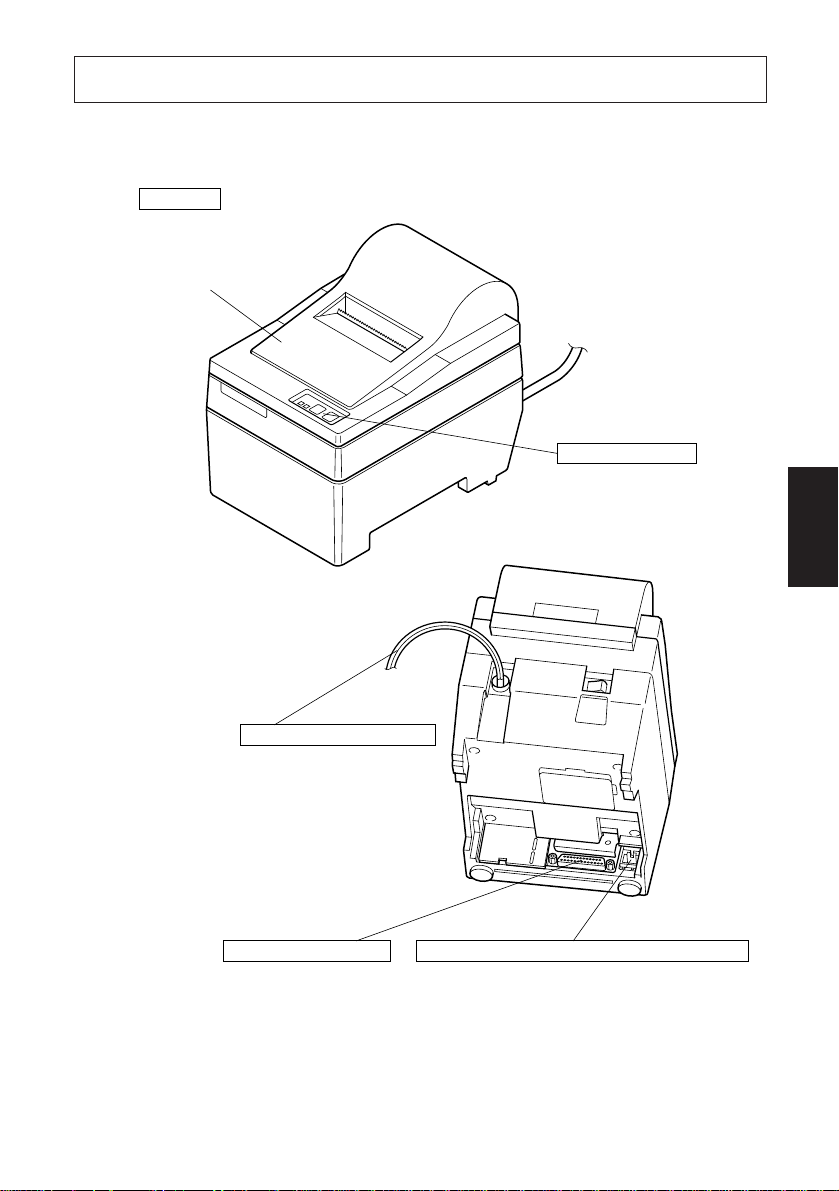
3. Identificazione delle parti e nomenclatura
Tipo SP210
Coperchio
Protegge la stampante dalla
polvere e riduce il rumore.
Non aprire il coperchio
durante la stampa.
Pannello comandi
Dispone di due
interruttori di controllo
e due indicatori dello
stato della stampante.
ITALIANO
Cavo di alimentazione CA
Collegarlo ad una presa a
muro della tensione
specificata. La forma della
spina del cavo di
alimentazione CA varia a
seconda del paese di
destinazione.
Connettore interfaccia
Per collegare la
stampante al computer
ospite.
Connettore circuito pilota per unità periferiche
Per il collegamento a unità periferiche
come registri di cassa, ecc. Non
collegarlo ad un telefono.
Fig. 3-1 Vista esterna della stampante (tipo SP210)
– 70 –
Page 74
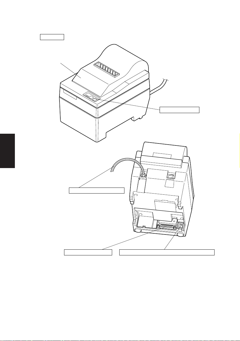
Tipo SP240
ITALIANO
Coperchio
Protegge la stampante dalla
polvere e riduce il rumore.
Non aprire il coperchio
durante la stampa.
Pannello comandi
Dispone di due
interruttori di controllo
e due indicatori dello
stato della stampante.
Cavo di alimentazione CA
Collegarlo ad una presa a
muro della tensione
specificata. La forma
della spina del cavo di
alimentazione CA varia
a seconda del paese di
destinazione.
Connettore interfaccia
Per collegare la
stampante al computer
ospite.
Connettore circuito pilota per unità periferiche
Per il collegamento a unità periferiche
come registri di cassa, ecc. Non
collegarlo ad un telefono.
Fig. 3-1 Vista esterna della stampante (tipo SP240)
– 71 –
Page 75
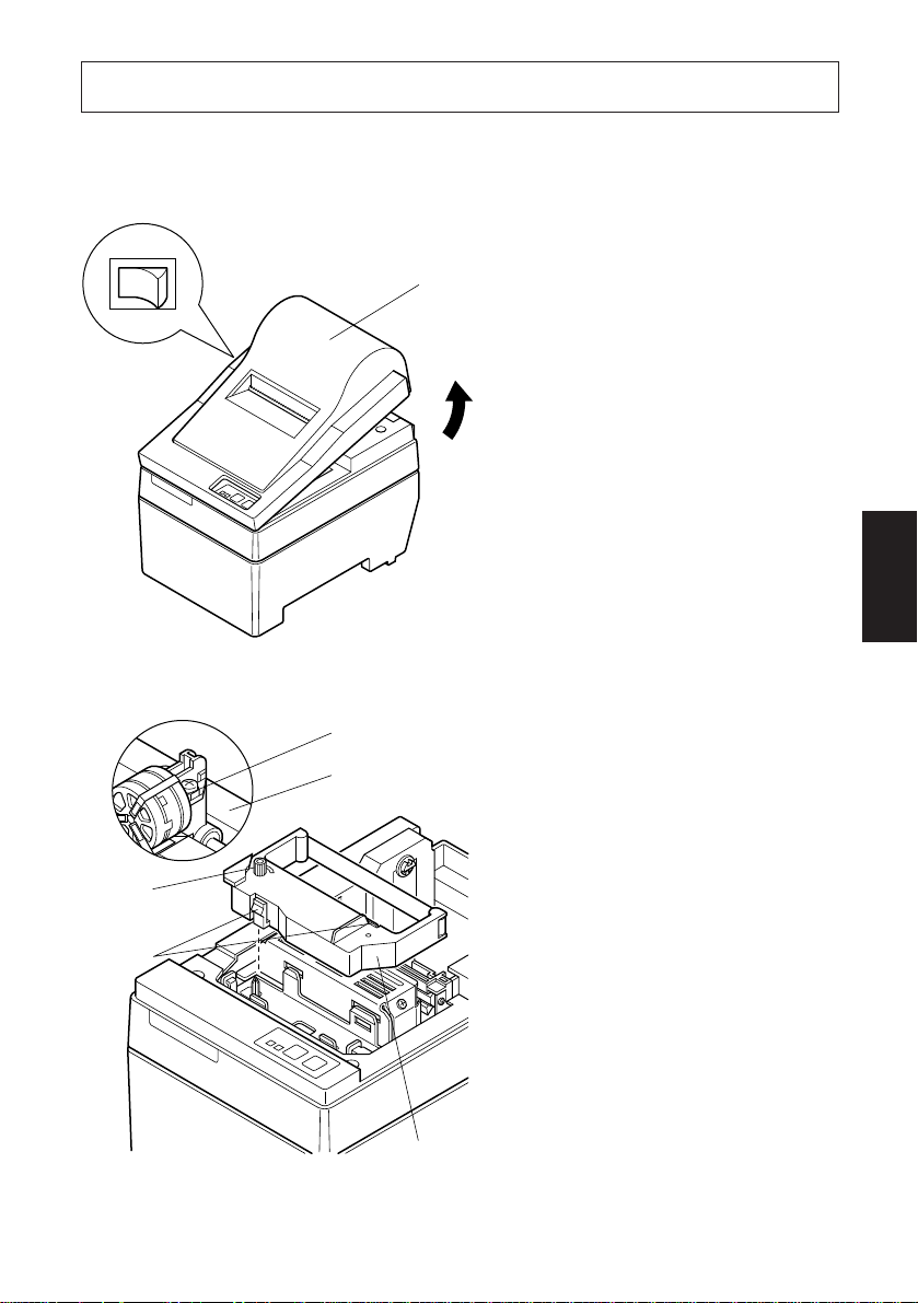
4. Inserimento della cartuccia nastro e della carta
4-1. Tipo SP210
4-1-1.Inserimento della cartuccia nastro
Coperchio
Spegnere
1 Spegnere la stampante.
2 Sollevare il coperchio di 3 cm
circa. Tenere il coperchio inclinato a questa angolazione e tirarlo verso di sè per rimuoverlo.
3 Inserire la cartuccia nastro nella
direzione mostrata nella Fig. 4-2
e premerla in basso per caricarla.
Se il caricamento della cartuccia
nastro non è soddisfacente, premere in basso la cartuccia nastro
girando la manopola di avanzamento nastro in direzione della
freccia.
ITALIANO
Fig. 4-1 Rimozione del coperchio
Testina di stampa
Nastro inchiostrato
Manopola di
avanzamento nastro
Parte
incassata
Fig. 4-2 Inserimento della cartuccia
nastro
4 Girare la manopola di avanza-
mento nastro della cartuccia nastro in direzione della freccia per
eliminare l’allentamento del nastro.
5 Montare il coperchio con il pro-
cedimento inverso a quanto descritto al punto 2 sopra.
Cartuccia nastro
– 72 –
Page 76

A
Fig. 4-3
ITALIANO
4-1-2.Inserimento della carta
Nota: Quando si rimuove la cartuccia
nastro, sollevare la parte A e
quindi rimuovere la cartuccia
tenendo la parte B come mostrato nella Fig. 4-3.
B
Coperchio
1 Sollevare il coperchio di 3 cm circa.
Tenere il coperchio inclinato a questa angolazione e tirarlo verso di sè
per rimuoverlo.
Interruttore
FEED
Fig. 4-4 Rimozione del coperchio
– 73 –
Page 77
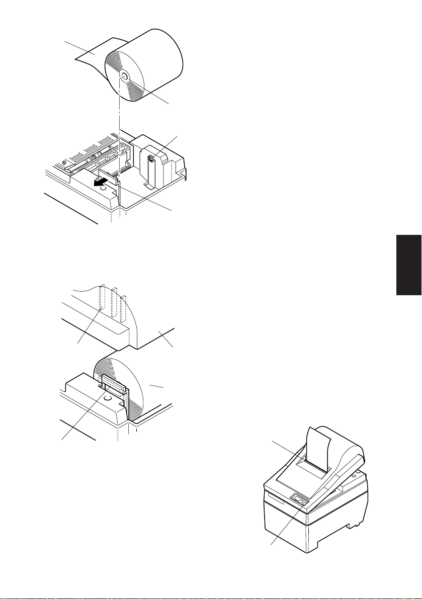
Rotolo di carta
Supporto rotolo carta
Fig. 4-5 Inserimento della carta
Costa di
posizionamento
Supporto rotolo carta
Anima
di cartone
Asse
Coperchio
Rotolo di
carta
2 Tagliare perpendicolarmente l’estre-
mità iniziale della carta del rotolo.
3 Verificare che la stampante sia accesa.
4 Osservando la direzione della carta del
rotolo, inserire l’estremità superiore
della carta sotto la guida della carta il
più possibile. Se il rotolo carta è installato, l’estremità superiore della carta fuoriesce automaticamente dall’uscita carta.
5 Spostare il supporto rotolo carta in
direzione della freccia e inserire il rotolo in modo che i fori nell’anima di
cartone siano allineati con gli assi del
supporto rotolo carta. Rilasciare il supporto rullo carta per fissare la carta.
6 Se l’anima di cartone del rotolo carta
non è stata allineata correttamente
con il supporto rotolo carta, il coperchio non può essere applicato correttamente finché non si corregge la posizione della carta.
7 Premere l’interruttore FEED (avan-
zamento carta) per far avanzare la
carta di circa 10 cm.
8 Inserire l’estremità superiore della
carta nella fessura della barra di strappo e quindi montare il coperchio con
il procedimento inverso di quello usato per rimuovere il coperchio al punto
1 sopra.
Nota: Quando il segno di fine carta
appare sulla carta, sostituire il
rotolo di carta prima che finisca.
Barra di
strappo
ITALIANO
Fig. 4-6
– 74 –
Interruttore FEED
Fig. 4-7
Page 78
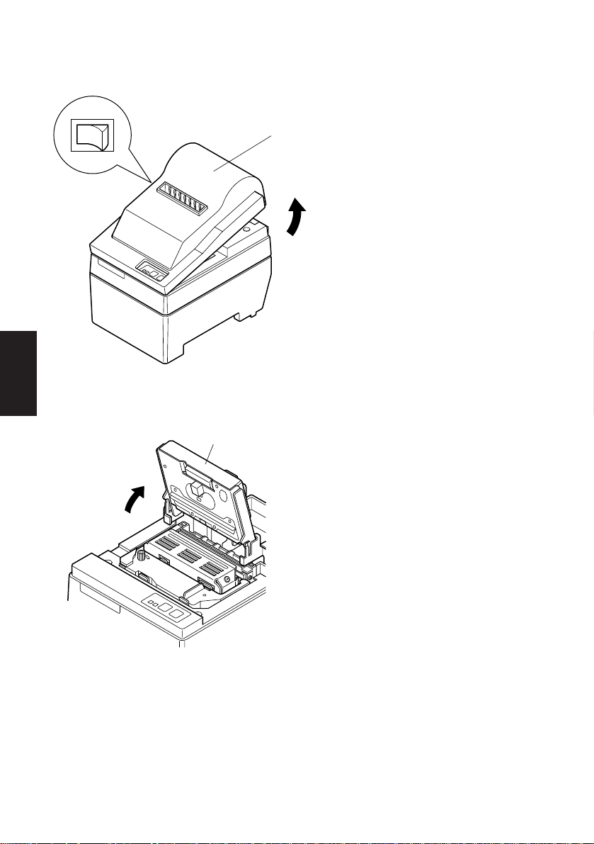
4-2. Tipo SP240
4-2-1.Inserimento della cartuccia nastro
Spegnere
ITALIANO
Fig. 4-8 Rimozione del coperchio
Taglierina automatica
Coperchio
1 Spegnere la stampante.
2 Sollevare il coperchio di 3 cm
circa. Tenere il coperchio inclinato a questa angolazione e tirarlo verso di sè per rimuoverlo.
3 Sollevare la taglierina automati-
ca e collocarla in posizione verticale, come mostrato nella Fig. 4-
9.
Fig. 4-9 Sollevamento della taglierina
automatica
– 75 –
Page 79
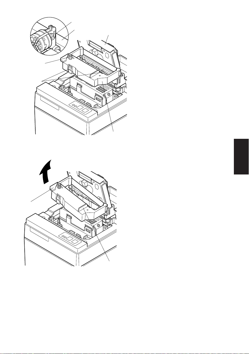
Testina di stampa
Nastro inchiostrato
Taglierina
automatica
Manopola di
avanzamento nastro
Parte
incassata
Cartuccia nastro
Fig. 4-10 Inserimento della cartuccia
nastro
4 Inserire la cartuccia nastro nella
direzione mostrata nella Fig. 410 e premerla in basso per caricarla. Se il caricamento della cartuccia nastro non è soddisfacente, premere in basso la cartuccia
nastro girando la manopola di
avanzamento nastro in direzione
della freccia.
5 Girare la manopola di avanza-
mento nastro della cartuccia nastro in direzione della freccia per
eliminare l’allentamento del nastro.
6 Chiudere la taglierina automati-
ca.
7 Montare il coperchio con il pro-
ITALIANO
cedimento inverso a quanto descritto al punto 2 sopra.
Nota: Quando si rimuove la car-
A
tuccia nastro, sollevare la
parte A e quindi rimuovere la cartuccia tenendo la
parte B come mostrato
nella Fig. 4-11.
B
Fig. 4-11
– 76 –
Page 80

4-2-2.Inserimento della carta
Interruttore
FEED
Coperchio
1 Sollevare il coperchio di 3 cm circa.
Tenere il coperchio inclinato a questa angolazione e tirarlo verso di sè
per rimuoverlo.
ITALIANO
Fig. 4-12 Rimozione del coperchio
Rotolo di carta
Anima di cartone
Asse
Supporto rotolo carta
Fig. 4-13 Inserimento della carta
2 Tagliare perpendicolarmente l’estre-
mità iniziale della carta del rotolo.
3 Verificare che la stampante sia ac-
cesa.
4 Osservando la direzione della carta
del rotolo, inserire l’estremità superiore della carta sotto la guida della
carta il più possibile. Se il rotolo
carta è installato, l’estremità superiore della carta fuoriesce automaticamente dall’uscita carta. Dopo che
sono fuoriusciti 2 cm di carta, la carta
viene tagliata automaticamente.
5 Spostare il supporto rotolo carta in
direzione della freccia e inserire il
rotolo in modo che i fori nell’anima
di cartone siano allineati con gli assi
del supporto rotolo carta. Rilasciare
il supporto rullo carta per fissare la
carta.
6 Se l’anima di cartone del rotolo car-
ta non è stata allineata correttamente con il supporto rotolo carta, il
coperchio non può essere applicato
correttamente finché non si corregge la posizione della carta.
– 77 –
Page 81

7 Premere l’interruttore FEED (avan-
zamento carta) per far avanzare la
carta di circa 10 cm.
Costa di
posizionamento
Supporto rotolo carta
Coperchio
Rotolo
di carta
Fig. 4-14
Taglierina
Fessura
di inserimento
carta
automatica
Fig. 4-15 Inserimento della carta nella
taglierina automatica
8 Inserire l’estremità superiore della
carta nella fessura carta della taglierina automatica.
• Quando si usa carta autocopiante,
inserire solo l’originale (il foglio
superiore) nella fessura della taglierina automatica. Inserire la carta su
cui si copia (il foglio inferiore) tra il
rullo e la taglierina automatica.
ITALIANO
– 78 –
Page 82

Foglio
superiore
Testina di stampa
Fessura di
inserimento carta
Rullo
Fessura di
inserimento
carta
Taglierina
automatica
Foglio superiore
Foglio inferiore
ITALIANO
Fig. 4-17 Uscita carta sul coperchio
Foglio inferiore
Testina di stampa
Fig. 4-16 Inserimento della carta nella taglierina automatica
(quando si usa carta autocopiante)
Uscita
carta
9 Tirare il bordo del carta per elimina-
re eventuali allentamenti e quindi
abbassare la taglierina automatica.
0 Inserire la carta attraverso l’apertu-
ra carta e quindi rimettere il coperchio seguendo in ordine inverso il
procedimento di rimozione.
Taglierina
automatica
Nota: Quando il segno di fine carta
appare sulla carta, sostituire
anteriore
il rotolo di carta prima che
finisca.
Rullo
Interruttore FEED
– 79 –
Fig. 4-18
Page 83

4-3. Rimozione della carta
Rimuovere il coperchio, quindi tagliare la carta vicino al retro della guida carta
e premere l’interruttore FEED per far fuoriuscire la carta rimanente nell’unità.
Quando la carta è finita la spia POWER lampeggia.
Nota 1. Rimuovere la carta rimanente nella stampante premendo l’interrut-
tore FEED.
2. Quando il segno di fine carta appare sulla carta, sostituire il rotolo
di carta prima che finisca.
3. Quando si rimuove l’anima di cartone del rotolo, aprire il supporto
rotolo carta.
4-4. Collegamento del cavo interfaccia
4-4-1.Installazione dell’anello di ferrite (solo UE)
1 Fissare l’anello di ferrite sul cavo
interfaccia seriale/parallelo come
Anello di ferrite
Interfaccia cavo
5 cm
massimo
mostrato nell’illustrazione. Se
l’anello di ferrite non è aperto, usare
un cacciavite per forzarlo aperto,
facendo attenzione a non danneggiare l’anello o la chiusura.
2 Far passare la fascetta di fissaggio
attraverso l’anello di ferrite.
3 Far passare la fascetta intorno al
cavo e fissarla.
Tagliare via l’eccesso con delle forbici.
Applicare l’anello di ferrite solo ai
cavi di stampanti venduti nell’UE.
ITALIANO
Fig. 4-19
Fascetta di
fissaggio
Tirare fuori
e tagliare
– 80 –
Page 84
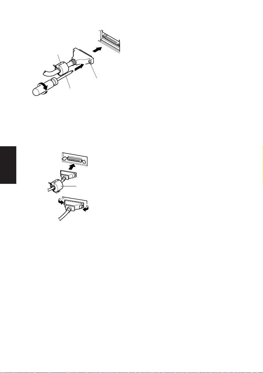
4-4-2.Cavo interfaccia seriale
Anello di ferrite
(solo UE)
Cacciavite
Fig. 4-20 Collegamento del cavo
interfaccia
4-4-3.Cavo interfaccia parallelo
ITALIANO
Anello di ferrite
(solo UE)
Fig. 4-21 Collegamento del cavo
interfaccia parallelo
Viti
1 Spegnere sia il computer ospite che
la stampante.
2 Inserire il connettore ad un capo del
cavo interfaccia nel connettore sulla stampante e l’altro connettore nel
connettore sul computer ospite.
3 Fissare le viti destra e sinistra dei
rispettivi connettori interfaccia per
fissare in posizione i connettori.
1 Spegnere sia il computer ospite che
la stampante.
2 Inserire un terminale del cavo
interfaccia nel connettore sulla stampante, come mostrato nella figura, e
fissarlo con il morsetto.
3 Inserire l’altro terminale del cavo
interfaccia nel connettore sul computer ospite e fissare anche questo
con il morsetto.
– 81 –
Page 85

5. Pannello comandi
5-1. Funzionamento basilare
ON LINEPOWER FEED
1 Interruttore ON LINE
Alterna lo stato della stampante tra
“on-line” e “off-line”. La
commutazione tra “on-line” e “offline” è possibile solo quando c’è
carta inserita nella stampante.
3 4 1 2
2 Interruttore FEED
• Quando si preme questo interrutto-
Fig. 5-1 Pannello comandi
re e lo si rilascia entro 0,5 sec., la
carta avanza di una riga.
• Quando si tiene premuto questo interruttore per più di 0,5 sec., la carta
avanza continuamente.
(L’operazione di avanzamento carta sopra descritta è possibile in entrambi i modi “on-line” e “off-line”.
3 Spia POWER (LED verde)
• Si illumina quando la stampante è accesa.
• Lampeggia quando la carta è esaurita, si verifica un errore meccanico, c’è un
allarme dovuto a surriscaldamento della testina o si verifica un errore CPU.
• Se la carta è esaurita, inserire altra carta e premere l’interruttore ON LINE.
• Se la spia POWER lampeggia a causa di un errore meccanico, spegnere la
stampante ed eliminare la causa dell’errore meccanico, quindi riaccendere la
stampante per inizializzarla.
• Se la spia POWER lampeggia a causa dell’allarme di surriscaldamento
testina, la stampante viene reimpostata automaticamente quando la temperatura della testina scende.
4 Spia ON LINE (LED verde)
LED illuminato: Stampante “on-line”
LED spento: Stampante “off-line”
LED lampeggiante: Errore CPU
ITALIANO
Quando la spia POWER e la spia ON LINE si illuminano contemporaneamente, si è verificato un errore CPU.
– 82 –
Page 86

5-2. Operazioni con gli interruttori (operazioni combinate
degli interruttori)
1 <STAMPA AUTOMATICA>
FEED + POWER ON (accendere tenendo premuto l’interruttore FEED)
La stampa automatica viene eseguita secondo le impostazioni degli interruttori VER NO., DIP e l’ordine dei caratteri. Se si tiene premuto l’interruttore
FEED o se si preme l’interruttore FEED alla fine della stampa automatica,
solo i caratteri sono stampati ripetutamente.
ITALIANO
Fig. 5-2 Esempio di stampa automatica
(quando si usa la stampante a interfaccia seriale RS-232C)
– 83 –
Page 87
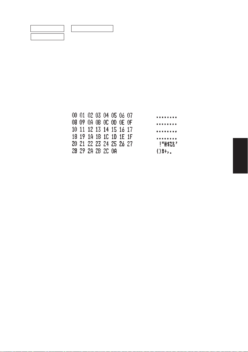
2 <Modo di scaricamento esadecimale>
ON LINE + POWER ON (accendere tenendo premuto l’interruttore
ON LINE )
Ciascuno dei segnali inviati dal computer alla stampante viene stampato in
codice esadecimale.
Questa funzione permette di controllare se un codice di controllo inviato alla
stampante dal programma usato è corretto o meno. L’ultima riga non viene
stampata se i suoi dati non consistono di una riga completa. Tuttavia, se si
preme l’interruttore ON LINE per impostare il modo “off-line” l’ultima riga
viene stampata. Per disattivare questo modo, è necessario spegnere completamente la stampante.
Fig. 5-3 Esempio di stampa a scaricamento esadecimale
– 84 –
ITALIANO
Page 88
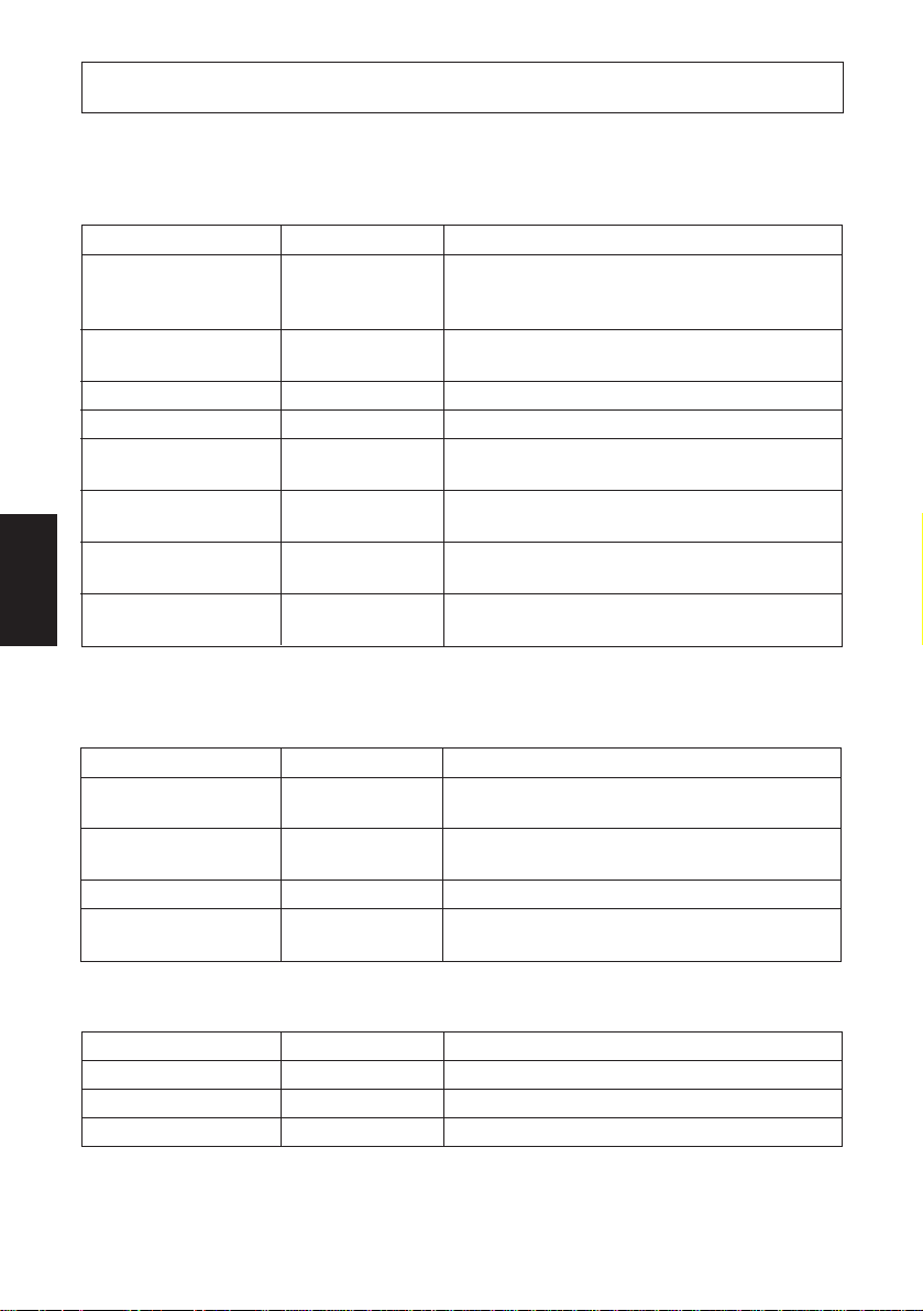
6. Codici di controllo
Modo STAR
6-1. Codici di controllo usati nell’impostazione dei caratteri
Codici di controllo Codici esadecimali Funzione
<ESC> “R” n 1B 52 n Seleziona il gruppo caratteri internazionale. Il default
è in base all’impostazione degli interruttori Dip 3, 4
e 5.
<ESC> “M” 1B 4D Seleziona il formato caratteri 7 × 7 (mezzi punti)
(impostazione default)
<ESC> “P” 1B 50 Seleziona il formato caratteri 9 × 7 (mezzi punti)
<SO> 0E Seleziona il modo caratteri espanso
<SI> 0F Disattiva il modo caratteri espanso
(impostazione default)
<DC4> 14 Disattiva il modo caratteri espanso
ITALIANO
<ESC> “W” “1” 1B 57 31 Seleziona il modo caratteri espanso
<ESC> “W” <1> 1B 57 01
<ESC> “W” “0” 1B 57 30 Disattiva il modo caratteri espanso
<ESC> “W” <0> 1B 57 00 (impostazione default)
6-2. Codici di controllo usati nell’impostazione del modo di
stampa
(impostazione default)
Codici di controllo Codici esadecimali Funzione
<ESC> “4” 1B 34 Selezione della stampa in colore rosso (abilitata per
la SP216/246)
<ESC> “5” 1B 35 Deselezione della stampa in colore rosso (abilitata
per la SP216/246) (impostazione default)
<ESC> “E” 1B 45 Selezione del modo stampa enfatizzata
<ESC> “F” 1B 46 Deselezione del modo stampa enfatizzata
(impostazione default)
6-3. Codici di controllo usati nella spaziatura delle righe
Codici di controllo Codici esadecimali Funzione
<LF> 0A Avanzamento di riga
<CR> 0D Avanzamento di riga (come LF)
<ESC> “a” n 1B 61 n Avanzamento della carta di n righe
– 85 –
Page 89

6-4. Codici di controllo usati per unità periferiche
Codici di controllo Codici esadecimali Funzione
<ESC> <BEL> n1 n2 1B 07 n1 n2 Regola l’ampiezza degli impulsi di pilotaggio per
l’unità periferica (impostazione default)
<BEL> 07 Comando di pilotaggio differito “A” per unità peri-
ferica 1
<FS> 1C Comando di pilotaggio immediato “B” per unità
periferica 1
6-5. Controllo della taglierina automatica (solo tipo SP240)
Codici di controllo Codici esadecimali Funzione
<ESC> “d” “0” 1B 64 30 Comando di taglio completo alla taglierina
<ESC> “d” <0> 1B 64 00 automatica
<ESC> “d” “1” 1B 64 31 Comando di taglio parziale alla taglierina
<ESC> “d” <1> 1B 64 01 automatica
<ESC> “d” “2” 1B 64 32 Invia alla taglierina automatica un comando di taglio
<ESC> “d” <2> 1B 64 02 completo dopo l’alimentazione della carta
<ESC> “d” “3” 1B 64 33 Invia alla taglierina automatica un comando di taglio
<ESC> “d” <3> 1B 64 03 parziale dopo l’alimentazione della carta
6-6. Altri codici di controllo
Codici di controllo Codici esadecimali Funzione
<CAN> 18 Cancella i dati di stampa nel buffer
<ENQ> *
<DC1> *
<DC3> *
<ESC> “@” 1B 40 Inizializza la stampante
<ESC> “e” “0” 1B 65 30 Interruttore ON LINE/FEED valido
<ESC> “e” <0> 1B 65 00 (impostazione default)
<ESC> “e” “1” 1B 65 31 Interruttore ON LINE/FEED non valido
<ESC> “e” <1> 1B 65 01
<ESC> “f” “0” 1B 66 30 Interruttore ON LINE valido
<ESC> “f” <0> 1B 66 00 (impostazione default)
<ESC> “f” “1” 1B 66 31 Interruttore ON LINE non valido
<ESC> “f” <1> 1B 66 01
1 : Valido solo per RS-422A.
*
1 05 Interrogazione stampante
1 11 Imposta la modalità di selezione
1 13 Deseleziona la stampante
– 86 –
ITALIANO
Page 90
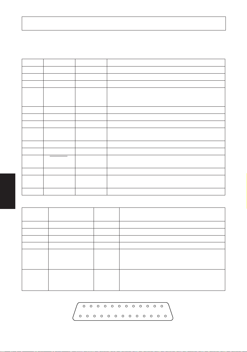
Appendix A: Serial Interface
A-1. Connectors and Signals
RS-232C
Pin no. Signal name I/O direction Function
1 F-GND — Frame ground
2 N/C Not connected
3 RXD IN Received data
4 RTS OUT Data transmission request signal. This is always
5-6 N/C Not connected
7 S-GND — Signal ground
8-10 N/C Not connected
11 RCH OUT When the printer is ready to receive data, the signal line
12 N/C Not connected
13 GND — Signal ground
14 FAULT OUT When printer error occurs (such as paper out, mechani-
APPENDIX
15-19 N/C Not connected
20 DTR OUT Data terminal ready signal. When the printer is ready to
21-25 N/C Not connected
“SPACE” when the printer is turned on. (Always
“SPACE” status)
is same as pin 20.
cal error, etc.) this signal changes to “MARK”.
receive data, this signal changes to “SPACE”.
RS-422A
Pin no. Signal name
9 SD (+) OUT Transmitted data
10 SD (–) OUT Transmitted data
17 RD (+) IN Received data
18 RD (–) IN Received data
24 RS (+) OUT Data transmission request signal. When the
25 RS (–) OUT Data transmission request signal. When the
14
113
Fig. A-1 Serial interface connector
I/O
direction
Function
printer is ready to receive data, this signal
changes to “SPACE”.
printer is ready to receive data, this signal
changes to “SPACE”.
25
– 87 –
Page 91

A-2. Interface Connections
The following is a basic example of interface connections. (For interface
connections, refer to the specifications for the respective interface.)
F-GND
DCD
Host computer
(D-sub 25 pin)
1 F-GND
2TXD
3RXD
4RTS
5CTS
6DSR
7S-GND
8DCD
20
Host computer
(D-sub 9 pin)
1 F-GND
2RXD
Printer side
(D-sub 25 pin)
1
2
3
4
5
6
7
14
20DTR
Printer side
(D-sub 25 pin)
1
2
N/C
RXD
RTS
N/C
N/C
S-GND
FAULT
DTR
APPENDIX
N/C
3TXD
4DTR
5S-GND
6DSR
7RTS
8CTS
9
Fig. A-2 Example of interface connections
– 88 –
3
4
5
6
7
14
20RI
RXD
RTS
N/C
N/C
S-GND
FAULT
DTR
Page 92

A-3. Dip Switch Setting
Each of the switches in the DIP switch array is factory preset to ON. Be sure to
turn the power to both the printer and host computer off before changing the
setting of the DIP switches.
The dip switch array will appear when the ROM cover is removed.
ROM cover
Power off
ON
OFF
DIP switch 1
101
DIP switch 2
(RS-422A only)
61
Fig. A-3 DIP switch array
APPENDIX
■ DIP-SW 1 Factory presetting: all on
Switch Function ON OFF
1 Command mode STAR mode VeriFone mode
2 Control code CR Invalid Valid
3
4 International character set Refer to the following.
5
6
7
8 Data bit 8-data bit 7-data bit
9 Parity check No Yes
10 Parity Odd Even
Data transmission rate Refer to the following.
International character set
Switch U.S.A. France Germany England Denmark Sweden Italy Spain
3 ON OFF ON OFF ON OFF ON OFF
4 ON ON OFF OFF ON ON OFF OFF
5 ON ON ON ON OFF OFF OFF OFF
– 89 –
Page 93

Data transmission rate (baud rate)
Baud rate Switch 6 Switch 7
1200 OFF OFF
2400 OFF ON
4800 ON OFF
9600 ON ON
DIP SW 2 (RS-422A interface only) All switch settings are ON when the
printer is shipped from the factory.
SW Function ON OFF
2-1
2-2 Device address See table below
2-3
2-4
2-5 When turning DC1, DC3 valid mode Select Deselect
the power on. DC1, DC3 invalid mode
Addressable mode
2-6 Data composition XON/XOFF DTR
Mode DC1 Addressable mode DC1
DC3 #1 #2 #3 #4 #5 #6 #7 #8 #9 #10 #11 #12 #13 #14 DC3
invalid
mode mode
1 ON OFF ON OFF ON OFF ON OFF ON OFF ON OFF ON OFF ON OFF
2 ON ON OFF OFF ON ON OFF OFF ON ON OFF OFF ON ON OFF OFF
3 ON ON ON ON OFF OFF OFF OFF ON ON ON ON OFF OFF OFF OFF
4 ON ON ON ON ON ON ON ON OFF OFF OFF OFF OFF OFF OFF OFF
Deselect Select
(Not used)
valid
APPENDIX
– 90 –
Page 94
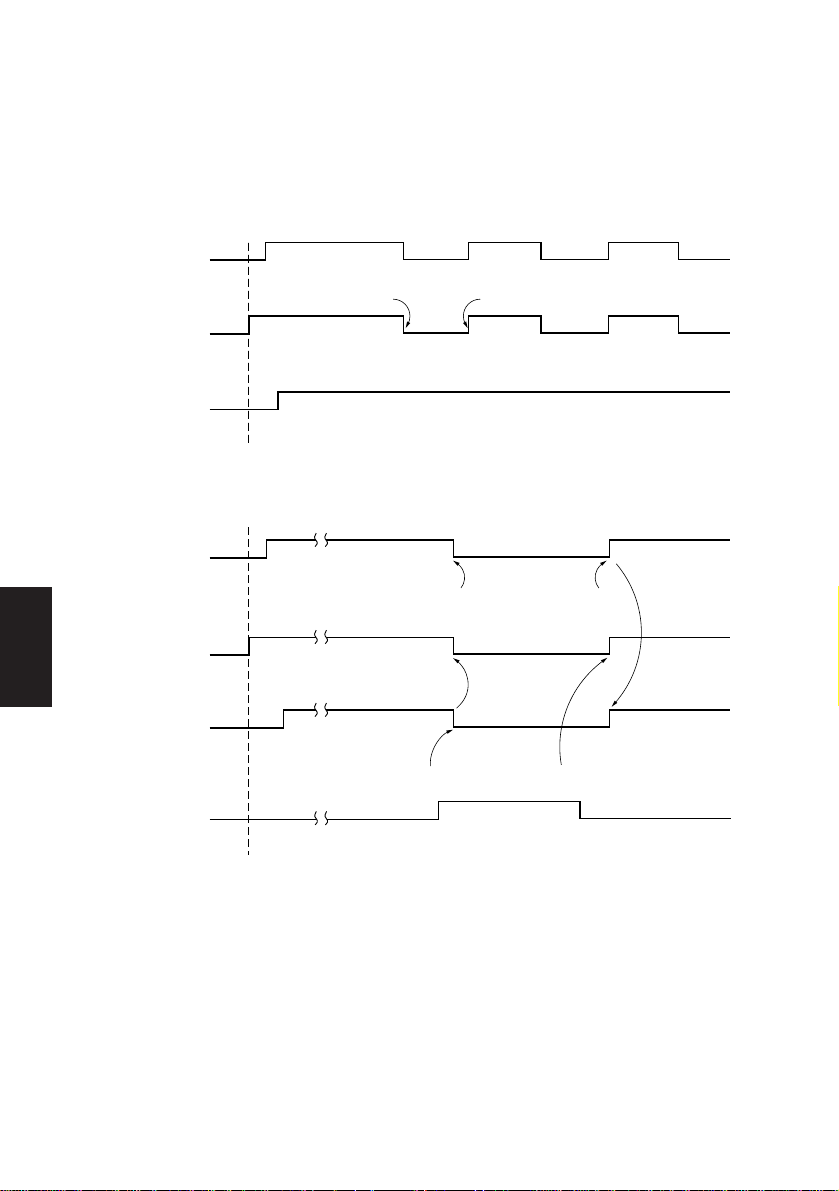
A-4. Communication Protcol
A-4-1. DTR mode
This is normally the mode for the RS-232C interface. This mode is enabled for
the RS-422A interface when the DIP switch 2-6 is set to OFF.
Signals are controlled using the DTR line as BUSY flag.
Data Data
OFF LINE ON LINE
Press the ONLINE button
after loading paper.
APPENDIX
When printing
RXD
DTR
Printing
when paper is out
RXD
DTR
PAPER OUT
signal
Data
Buffer full Buffer empty
Power on
Paper end
Power on
If printer errors do not occur after the power is turned on, the DTR signal line
changes to “SPACE”.
When the host computer confirms that the DTR signal line is set to “SPACE”, the
host computer sends the data text via the RXD signal line to the printer. Also, the
printer will set the DTR signal line to “MARK” when the empty space in the data
– 91 –
Page 95

buffer is below 256 bytes. After the host computer detects that the DTR signal line
is at “MARK”, transmission of the data text is stopped. In this instance, data can
still be received up until the data buffer becomes completely full.
When the empty space in the data buffer is increased by following printing (when
the data in the data buffer is reduced to 256 bytes or less), the printer sets the DTR
signal line to “SPACE”.
Data buffer
Full Near Full
Empty area
256 bytes
DTR"MARK"
Near Empty Empty
Reception data
256 bytes
DTR"SPACE"
[Paper out]
When the “paper out” detector senses the end of the paper, the printer stops
printing after printing or feeding a maximum of two more lines on the paper.
Immediately after a “paper out” condition is detected, the printer sets to OFF
LINE and the DTR changes to “MARK”. (To reset printer after a “paper out”,
load paper into the printer and press the ON LINE switch to set the printer to ON
LINE.)
[Mechanical error]
Mechanical errors are detected when the motor locks and the unit will not print.
Immediately after a mechanical error occurs, the printer sets the DTR to
“MARK” and then sets the printer to OFF LINE. To cancel a mechanical error,
turn the power to the printer off and remove the cause of the error then turn the
power on again to reset the printer.
[Framing error]
A framing error occurs when “SPACE” is detected at the stop bit. When a framing
error or a vertical parity error occurs for the data which is received, the printer
prints out a “?” mark to indicate that the error occurred.
APPENDIX
– 92 –
Page 96

The following status modes are only valid for the RS-422A interface.
[Status]
b7 b6 b5 b4 b3 b2 b1 b0
Constantly
set at “0”
Vertical parity error
1: error
Framing error
1: error
Mechanical error
1: error
Paper empty
1: empty
Buffer empty
1: empty
Buffer overflow
1: overflow
Compulsion switch
High level
(Switch is set to ON)
APPENDIX
[Compulsion switch]
When pin 6 of the peripheral unit drive circuit connector is set “HIGH”, status bit
7 becomes “1”.
– 93 –
Page 97

A-4-2. X-ON/X-OFF mode
This mode is enabled for the RS-422A interface when the DIP switch 2-6 is
set to ON.
X–ON X–OFF X–ON X–OFF X–ON
TXD
RXD
Printing
Paper out
signal
ON LINE
lamp
ON
OFF
Power ON Load paper and press
Data Data Data
Paper out
the ON LINE switch.
If printer errors do not occur after the power is turned on, the printer outputs a XON (DC1 by control code; 11H by hexadecimal data) signal on the TXD signal
line. When the host computer receives the X-ON signal, the host computer
transmits the data to the RXD signal line.
The printer outputs a X-OFF (DC3, 13H) signal when the empty space in the
buffer reduced below 256 bytes. When the host computer receives the X-OFF
signal, it halts output of data. However, the printer can continue receiving data
until the buffer becomes completely full.
The printer outputs an X-ON signal when the data in the buffer is printed out and
drops to below 256 bytes.
APPENDIX
– 94 –
Page 98

Data buffer
Full
Remainder
256 bytes
X-OFF X-ON
Near Full
Near Empty Empty
256 bytes
[Paper out]
When the “paper out” detector senses the end of the paper, the printer outputs XOFF signal and stops printing after printing or feeding a maximum of two more
lines on the paper. To reset printer after a “paper out”, load paper into the printer
and press the ON LINE switch to set the printer to ON LINE.
[Mechanical error]
Mechanical errors are detected when the motor locks and the unit will not print.
After a mechanical error occurs, the printer outputs X-OFF signal and then sets
the printer OFF LINE. To cancel a mechanical error, turn the power off and
remove the cause of the error, then turn the power on again to reset the printer.
[Status]
b7 b6 b5 b4 b3 b2 b1 b0
0
APPENDIX
Constantly
set at “0”
Vertical parity error
1: error
Framing error
1: error
Mechanical error
1: error
Paper empty
1: empty
Buffer empty
1: empty
Buffer overflow
1: overflow
Compulsion switch
High level
(Switch is set to ON)
[Framing error]
A framing error occurs when SPACE is detected at the stop bit. When a framing
error or a vertical parity error occurs for the data which is received, the printer
prints out a “?” mark to indicate that the error occurred.
[Compulsion switch]
When pin 6 of the peripheral unit drive circuit connector is set at “HIGH”, status
bit 7 becomes “1”.
– 95 –
Page 99

Appendix B: Parallel Interface
B-1. Interface Specifications
The operating specifications of the parallel interface are as follows.
(1) Data transfer rate : 1000 to 6000 characters per second
(2) Synchronization : Via externally supplied STROBE pulses
(3) Handshaking : ACK and BUSY signals
(4) Logic level : Compatible with TTL level
B-2. Interface Timing
ACK
Approx.9 µs
Data
STROBE
TTT
BUSY
T:more than 0.5 µs
INPUTOUTPUT
Fig. B-1 Interface timing diagram
Signal Name Circuit Example
DATA 1-DATA 8
(To Printer)
STROBE
(To Printer)
BUSY, ACK
(From Printer)
4.7KΩ
1KΩ
100Ω
470pF
1.8KΩ
74HC Compatible
74HC Compatible
74LS Compatible
Fig. B-2 Typical interface circuit
– 96 –
APPENDIX
Page 100

B-3. Connectors and Signals
Pin No. Signal Name IN/OUT Function
1 STROBE IN Signals when data is ready to be read. Signal goes from
2-9 DATA1-8 IN These signals provide the information of the first to
10 ACK OUT A 9 microsecond LOW pulse acknowledges receipt of
11 BUSY OUT When this signal goes LOW, the printer is ready to
12 PAPER OUT OUT This signal is normally LOW. It will go HIGH if the
13 SELECTED OUT This signal is HIGH when the printer is online.
14-15 N/C Not connected
SIGNAL GND
16
17
APPENDIX
19-30 GND Twisted pair return signal ground level.
CHASSIS GND
18 +5VDC +5VDC (Max 50 mA)
31 RESET IN When this signal goes LOW, the printer is reset to its
32 ERROR OUT This signal is normally HIGH. This signal goes LOW
33 EXT GND External ground.
34 OUT1 OUT Unused.
35 N/C Not connected
36 The printer side is always set to HIGH.
HIGH to LOW (for at least 0.5 microsec.) when data is
available.
eighth bits of parallel data. Each signal is at HIGH level
for a logical 1 and at a LOW level for a logical 0.
data.
accept data. When the printer is in one of the conditions
below. “HIGH” is set.
1. Data being entered.
2. Off line.
3. Error condition.
printer runs out of paper.
Signal ground.
Chassis ground, isolated from logic ground.
power-on condition.
to signal that the printer cannot print due to an error
condition.
Refer to Item 8-4 Emergency Suspension.
(19) (36)
(1) (18)
Fig. B-3. Parallel interface connector (printer side)
This connector mates with an
Amphenol 57-30360 connector
– 97 –
 Loading...