

Page 1

USER’S MANUAL
LC-8021
DOT MATRIX PRINTER
PBA10HK 80825130
Page 2

Trademark acknowledgments
IS-NP192, LC-8021, LC-8211, LC24-30, LC24-300, NX-2450, NX-2480, SPC-8K : Star Micronics Co. Ltd.
LQ-850, LQ-860, LQ-1050, LQ-1060 : Seiko Epson Corporation
IBM PC, IBM Proprinter X24E, IBM Proprinter XL24E, IBM Proprinter X24, IBM Proprinter XL24 :
International Business Machines Corporation.
MS-DOS : Microsoft Corporation
Notice
• All rights reserved. Reproduction of any part of this manual in any form whatsoever, without STAR’s express
permission, is strictly forbidden.
• The contents of this manual are subject to change without notice.
• All efforts have been made to ensure the accuracy of the contents of this manual at the time of printing. However, should any errors be found, STAR would greatly appreciate being informed of them.
• The above notwithstanding, STAR can assume no responsibility for any errors in this manual.
Copyright 1997 Star Micronics Co., Ltd.
Page 3

About this manual
This manual describes how to set up, use, and care for the Star LC-8021 printer.
The following is a list of what you can expect to find in each chapter.
Chapter 1 Choosing a place for your printer, unpacking and setup,
ribbon cassette installation, loading paper, connecting to
your computer
Chapter 2 How to use the control panel
Chapter 3 How to use the printer’s Electronic DIP Switch (EDS)
Mode to set up the printer to match the needs of your
system and software
Chapter 4 How to set up for printing with MS-DOS
Chapter 5 Selecting the best type of paper, manual sheet feeding,
print area
Chapter 6 Optional accessories that are available for your printer
Appendix A Troubleshooting
Appendix B Specifications
Appendix C Interface pin outs
Appendix D Character sets
Appendix E Printer control codes
Appendix F Glossary
Appendix G Control panel operation guide
Page 4

Contents
Chapter 1: Printer Setup ... 1
Choosing a place for the printer ... 1
Unpacking the printer ... 2
General guide ... 3
Opening the front cover ... 4
Removing the front cover ... 4
Removing the protective materials ... 5
Installing the ribbon cartridge ... 6
Removing the ribbon cartridge ... 8
Connecting to a power outlet and turning power on and off ... 9
Loading paper ... 10
Connecting to your computer ... 11
Chapter 2: Control Panel Operations ... 15
Switching between on-line and off-line ... 15
Selecting a font ... 16
Line feed ... 16
Form feed ... 16
Paper eject ... 16
Micro feed ... 16
Changing the auto load position ... 17
Clearing the printer’s buffer ... 18
Initializing the printer ... 18
Entering the Multi-part Mode ... 18
Page 5

Chapter 3: Using the EDS Mode ... 19
About EDS Mode settings ... 19
Entering the EDS Mode ... 19
Selecting a bank ... 20
Selecting a switch ... 21
Changing a switch setting ... 21
Printing the current switch settings ... 21
Exiting the EDS Mode ... 21
EDS-1 Settings ... 22
EDS-2 Settings ... 31
Chapter 4: Using the Printer with MS-DOS ... 34
Setting up for printing with MS-DOS ... 34
Chapter 5: Paper Handling ... 35
Selecting paper types ... 35
Feeding a passbook into the printer ... 36
Feeding cut-sheet paper into the printer ... 37
Print area ... 38
Chapter 6: Optional Accessories ... 39
Serial Interface Unit (IS-NP192) ... 39
Serial-to-Parallel Interface Converter (SPC-8K) ... 40
Appendix A: Troubleshooting ... 41
Short test ... 41
Long test ... 41
Hexadecimal dump ... 42
Adjusting the dot alignment ... 42
Troubleshooting guide ... 44
Checking system software settings in MS-DOS ... 49
Page 6

Appendix B: Specifications ... 50
Appendix C: Interface Pin Outs ... 52
Appendix D: Character Sets ... 53
Appendix E: Printer Control Codes ... 65
Appendix F: Glossary ... 74
Appendix G: Control Panel Operation Guide ... 75
Page 7

1
Chapter 1: Printer Setup
This chapter contains important information on setting up your printer. Be sure
to read this chapter carefully before using the printer for the first time.
Choosing a place for the printer
Before actually unpacking the printer, you should take a few minutes to think
about where you plan to use it. Remember the following points when doing this.
Choose a firm, level surface where the printer will not be exposed to
✓
vibration.
The power outlet you plan to connect to for power should be nearby and
✓
unobstructed.
Make sure that the printer is close enough to your computer for you to
✓
connect the two with your printer cable.
Allow six inches (15 centimeters) of free space on either side and in the
✓
back of the printer.
Make sure that the printer is not exposed to direct sunlight.
✓
Make sure that the printer is well away from heaters.
✓
Make sure that the surrounding area is clean, dry, and free of dust.
✓
Make sure that the printer is connected to a reliable power outlet. It should
✓
not be on the same electric circuit as copiers, refrigerators, or other
appliances that cause power spikes.
Use a power outlet that matches the power rating noted on the label affixed
✓
to the bottom of your printer.
Make sure that the room where you are using the printer is not too humid.
✓
Page 8

2 Printer Setup
Unpacking the printer
Check to make sure that the carton contains each of the items shown in the
following illustration.
Printer
Ribbon cartridge
If anything is missing, contact the store where you bought the printer and ask
them to supply the missing part. Note that it is a good idea to keep the original
box and all the packing materials just in case you need to pack the printer up
again and send it somewhere at a later date.
Important!
There are several versions of this printer designed for different voltages. It is
not possible to change the voltage of a printer. If the voltage shown on the label
on the bottom of your printer does not match the voltage for your ar ea, contact
your dealer immediately.
User's manualPower code
Page 9

General guide
The following illustrations show the major components of the your printer.
General guide 3
Front cover
Power switch
Document
table
extension
Parallel interface
connector
Serial interface
connector
Platen knob
Control panel
Document table
Power terminal
Page 10
4 Printer Setup
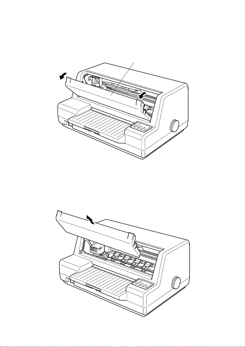
Opening the front cover
Pull on the left and right corners of the front cover to and swing it down
❏
until it is fully open.
Front cover
Removing the front cover
Once the front cover is fully open, carefully lift it straight up to remove it.
❏
To replace the front cover, lower the slots on the left and right of the cover
onto the tabs provided on the printer case.
Page 11
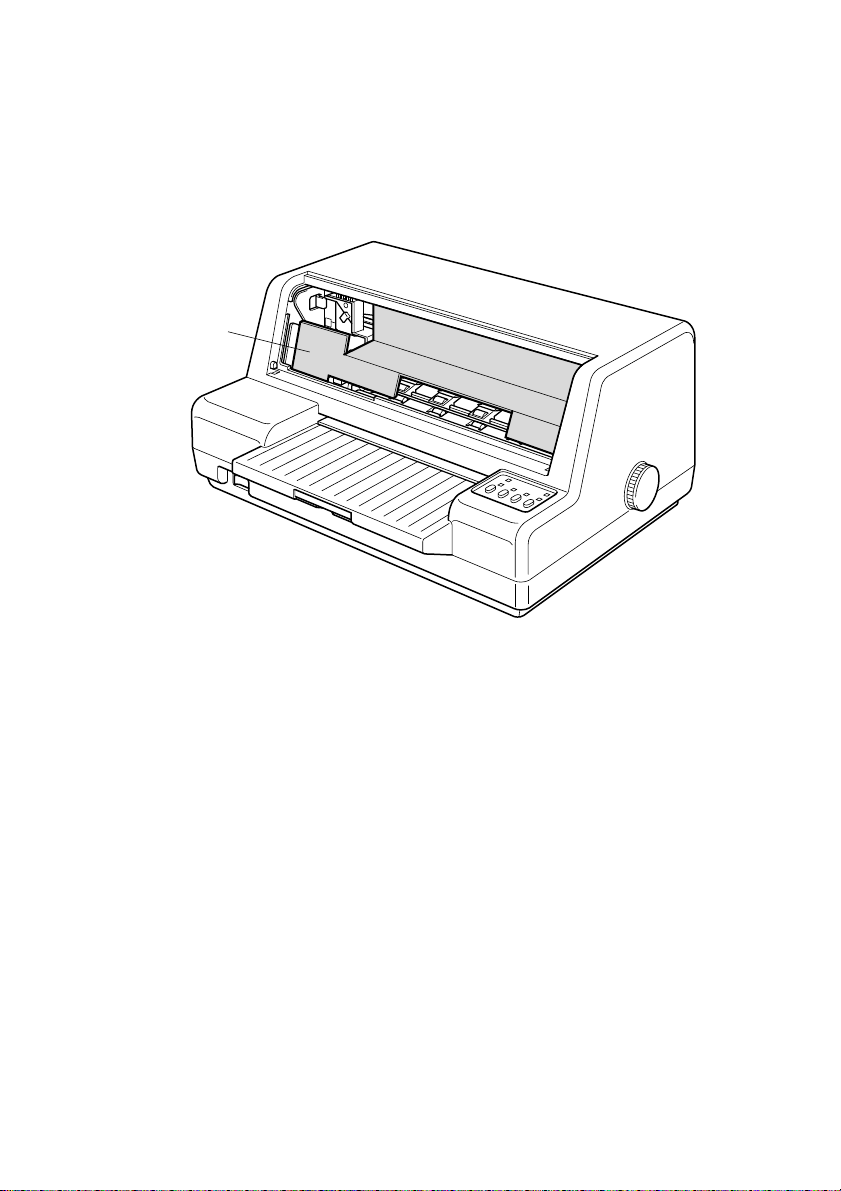
Removing the protective materials
Packing material in the printer protects its components during shipping.
❏
Before using the printer for the first time, be sure to remove the packing
material, which is located inside the front cover as shown in the illustration.
Cardboard
Removing the protective materials 5
Page 12
6 Printer Setup
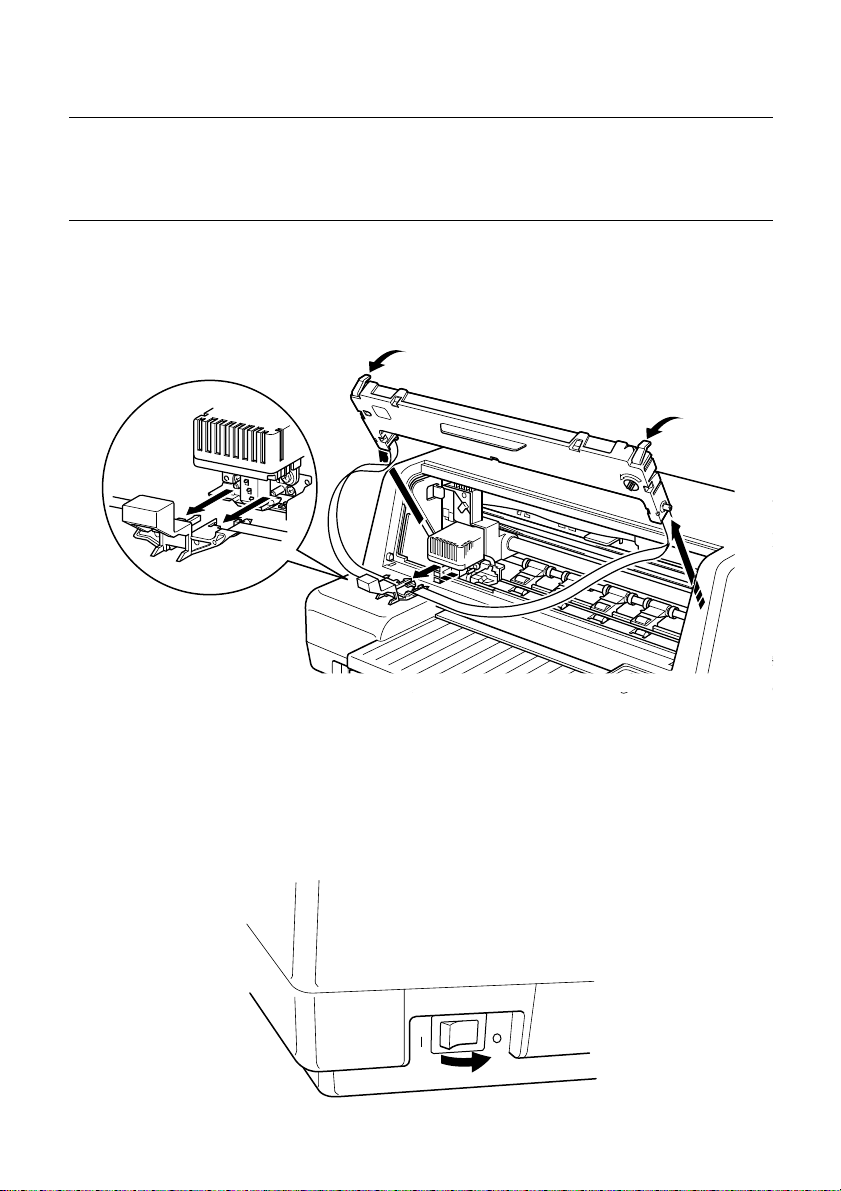
Installing the ribbon cartridge
Make sure that the printer is unplugged from its power outlet.
❏
Open the front cover of the printer.
❏
Note:
You will probably find later steps to perform if you remove the cover.
❏
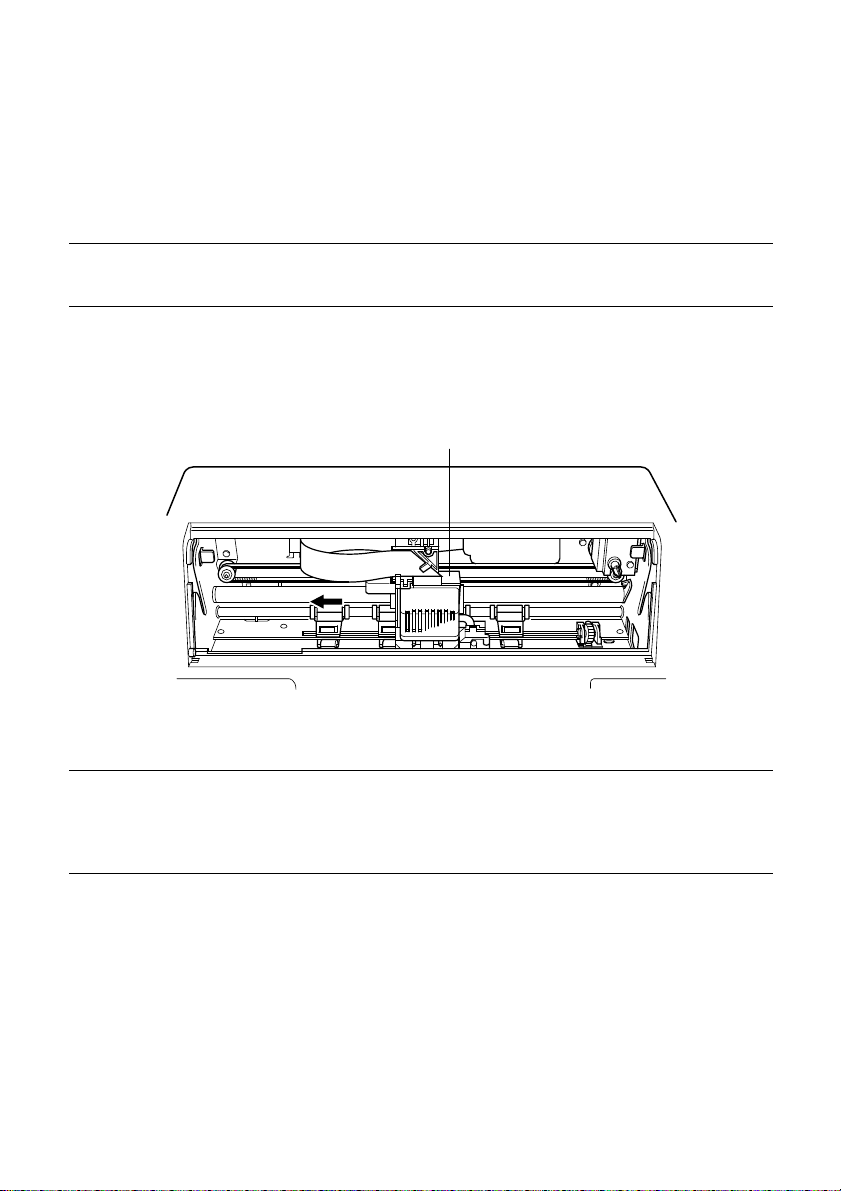
By hand, move the print head to the left as far as it will go, where there is a
cutout to allow easy installation and removal of the ribbon cartridge.
Carriage
Important!
Never try to move the print head while the printer is plugged into a power
outlet. Doing so can damage the printer. If you have just used the printer, let
the print head cool for a few minutes before you touch it.
Page 13
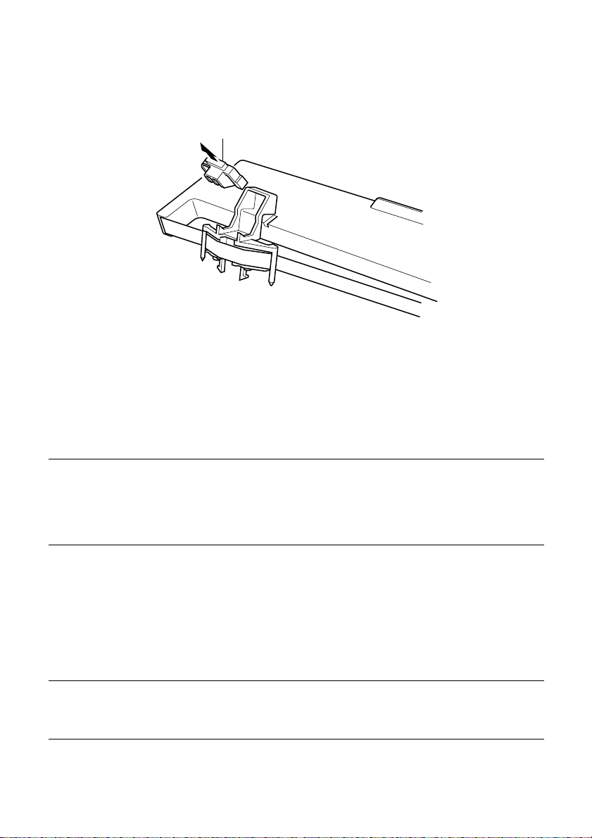
Remove the ribbon cartridge from its package and check to make sure its
❏
ribbon guide is correctly in place. If it isn’t, thread the ribbon through the
guide.
Ribbon guide holder
❏
Pull down on the ribbon guide to create considerable slack in the ribbon.
❏
Insert the two round tabs on either side of the ribbon cartridge into the two
slots inside the printer and slide the cartridge into place as you rotate the
knob on the right side of the cartridge to take up some of the slack in the
ribbon.
❏
Press on the top of the cartridge until it snaps securely into place.
Installing the ribbon cartridge 7
Note:
Note:
A ribbed ribbon advance shaft must enter into the hole on the back, right side
of the ribbon cartridge. You seem to have trouble getting the ribbon cartridge
to seat properly, try turning the knob of the ribbon cartridge slightly so the ribs
on the shaft align properly with the hole.
Once the ribbon cartridge is securely in place, use your thumb and
❏
forefinger to grasp the sides of the ribbon guide handle and attach the guide
to the carriage below the print head. The two metal rods below the print
head must fit into the holes provided in the ribbon guide. You will feel the
ribbon guide snap securely into place when it is installed correctly.
Angle the ribbon guide downwards so it slips under the print head, and then
straighten the guide to slip it onto rods below the print head.
Rotate the knob on the ribbon cartridge to take up any slack in the ribbon.
❏
Page 14

8 Printer Setup
Close the front cover of the printer.
❏
Ribbon guide
Important!
Printing that is poor quality or too light is almost always due to a ribbon that is
simply worn out or “used up.” If you experience problems with print quality,
check the condition of the ribbon. If the black part looks gray and well-worn,
replace the ribbon with a new one.
Print head
Metal rods
Knob
Slot
Slot
Removing the ribbon cartridge
Use the following procedure to remove the ribbon cartridge from the printer
when you want to replace it with a new one.
❏
Make sure that the printer is unplugged from its power outlet.
❏
Open the front cover of the printer.
Note:
You will probably find later steps to perform if you remove the cover.
By hand, move the print head to the left as far as it will go, where there is a
❏
cutout to allow easy installation and removal of the ribbon cartridge.
Page 15
Important!
Never try to move the print head while the printer is plugged into a power
outlet. Doing so can damage the printer. If you have just used the printer, let
the print head cool for a few minutes before you touch it.
❏
❏
Connecting to a power outlet and turning power on and off 9
Pull on the ribbon guide below the print head to detach it.
Pull on the top of the ribbon cartridge and then carefully lift up the
cartridge to remove it from the printer.
Use the procedure under “Removing the protective materials” on page 5 to
❏
install a new cartridge.
Connecting to a power outlet and turning power on and off
Make sure the power switch on the front of the printer is in the OFF
❏
position (O).
ON
OFF
Page 16
10 Printer Setup
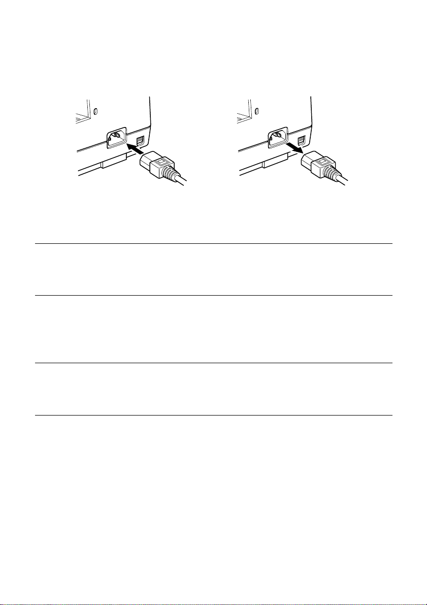
Securely attach the power cord to the power terminal on the back of the
❏
printer.
Plug the other end of the power cord into a grounded wall outlet.
❏
Caution!
If the voltage marked on the bottom of your printer does not match the voltage
from the outlet you are using, do not plug in the power cord. Contact your
dealer for assistance.
Use the printer’s power switch to turn power on (|) to turn power on and
❏
OFF (O).
Note:
W e recommend that you unplug the printer from the power outlet whene ver you
do not plan to use it for long periods. Because of the this, you should locate the
printer so that the power outlet it is plugged into is nearby and easy to access.
Loading paper
This section tells you how to load cut-sheet paper. Note that you can also use
passbook. For details on using passbook, see “Paper Handling” on page 35 of
this manual.
❏
Check that the control panel’s POWER indicator is flashing, which shows
that there is no paper in the printer.
❏
When printing on 4-ply or 5-ply paper, the Multi-Part Mode should be
used. Check to make sure that the control panel’s MULTI-PART indicator
is lit. If it isn’t, press the control panel’s MULTI-PART button.
Page 17
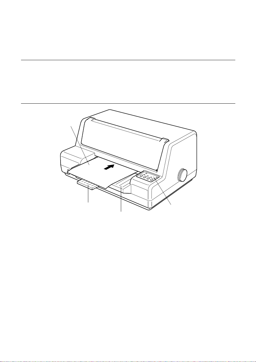
❏ Insert the paper into the printer as far as it will go, sliding its left side
Important!
If the paper is not inserted straight into the printer, it will be considered a
loading error and the paper will be ejected. Be sure to insert the paper
correctly.
Inserting the paper with its left side more than 7 mm to the right of the left
guide will be considered an error and the paper will be ejected.
against the printer’s left guide.
Paper
Connecting to your computer 11
Document table extension
Document table
The paper will automatically be fed into the printer.
If your are using letterhead, make sure the paper is facing up, with the top
towards the printer.
❏ Start the printing operation from your software application.
❏ After the printing is complete, press EJECT to eject the paper from the
printer.
Connecting to your computer
Your printer comes equipped with two interfaces built in as standard: one
parallel interface and one serial interface.
This printer does not come with cables, so you must purchase one separately to
match the needs of you computer.
Control panel
Page 18
12 Printer Setup
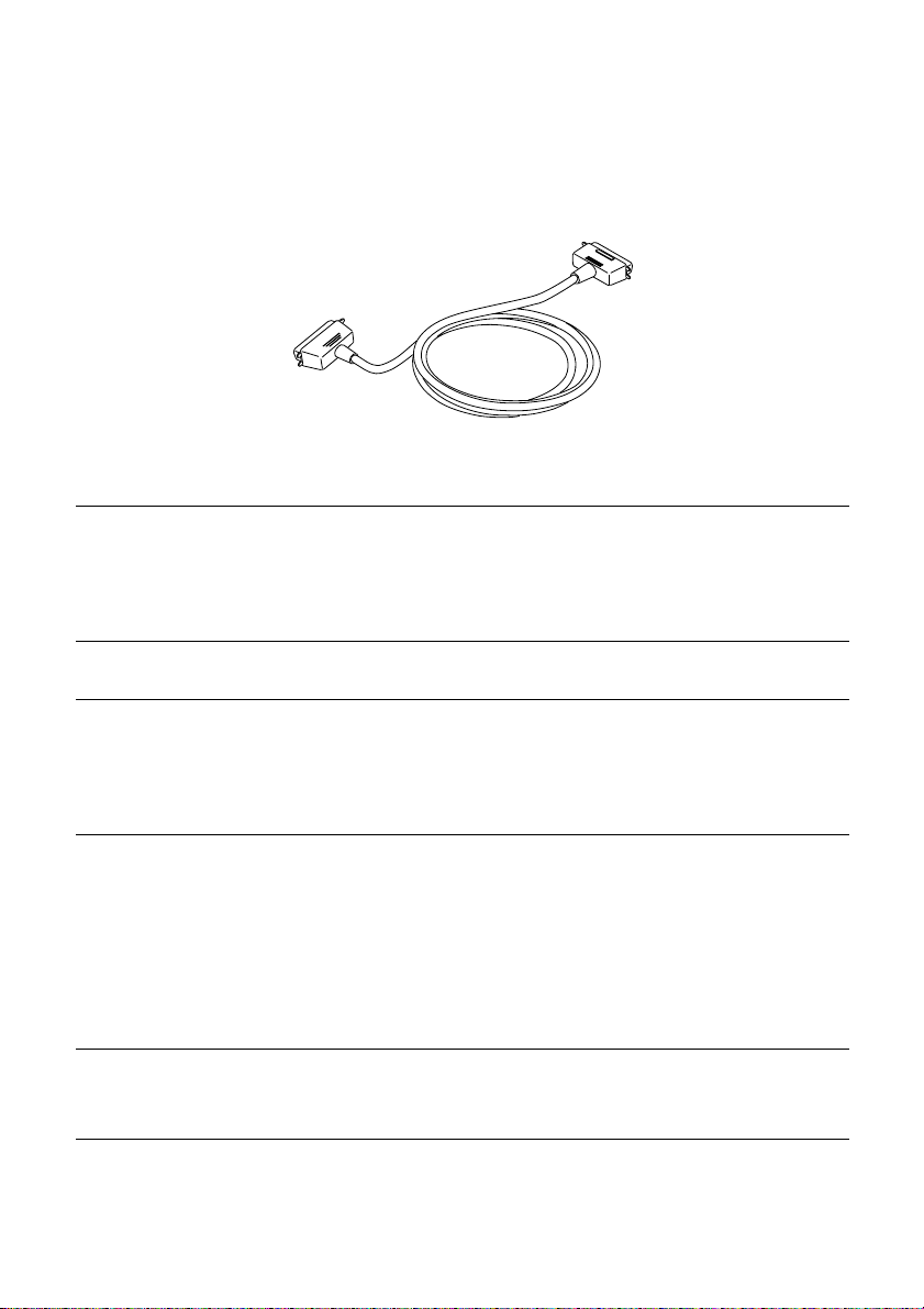
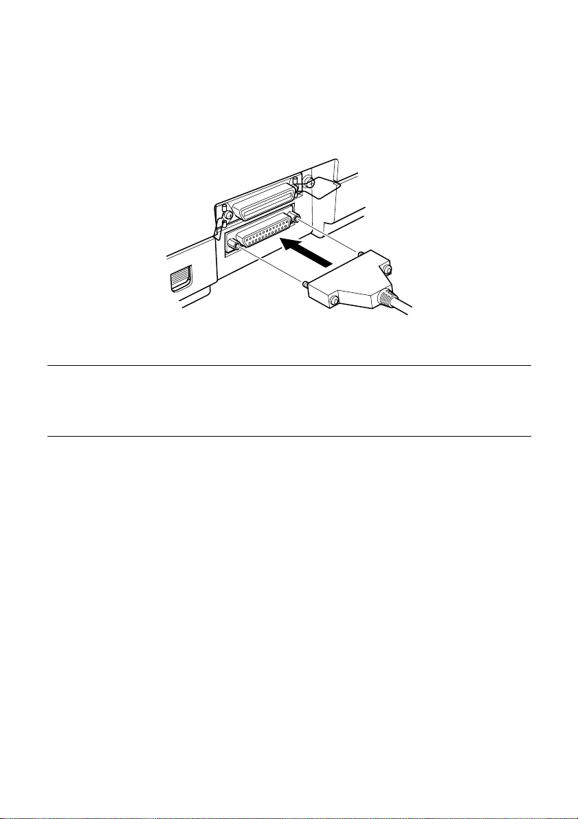
To connect with a parallel cable
For connection to the parallel interface, you will probably want to use a standard
parallel cable, like the one shown below.
Note:
In addition to using the parallel interface as-is to connect a parallel interface,
you can also connect an optional serial-to-parallel converter (page 40) to
convert serial data fr om the computer to par allel data. This ef fectively pr ovides
two serial interfaces for connection of separate computers.
Important!
The following instructions apply to the Centronics parallel cable that is
suitable for use with an IBM-compatible personal computer. Note that they do
not apply to all types of computers and cables. If you are unsure about what
type of cable you should use, consult your dealer.
For an IBM-compatible personal computer:
✓ Use a standard 36-pin Centronics parallel cable.
✓ The parallel cable should be no longer than six feet (two meters). Longer
Important!
Make sure that the printer is unplugged from the AC outlet and that the
computer is turned off before connecting them.
cables can result in poor transfer of information.
Page 19

❏ Plug one end of the parallel cable into the parallel port of your computer.
The parallel port should be labeled “Printer,” “Parallel,” “PRN, ” “LPT1,” or
something similar.
❏ Plug the other end of the parallel cable into the socket on the back of the
printer and secure it in place with the clips.
To connect with a serial cable
For connection to the serial interface, you will probably want to use a standard
RS-232C cable, like the one shown below.
Connecting to your computer 13
Important!
• The following instructions apply to the serial cable that is suitable for use
• Make sure that the printer is unplugged from the AC outlet and that the
with an IBM-compatible personal computer. Note that they do not apply to all
types of computers and cables. If you are unsur e about what type of cable you
should use, consult your dealer.
computer is switched off before connecting them.
Page 20
14 Printer Setup
❏ Attach one end of the serial cable to a serial port of your computer (COM1,
COM2), and secure the connector with the screws provided on the plug.
❏ Plug the other end of the cable into the socket on the back of the printer and
secure it in place with the screws.
Note:
The parallel interface equipped on the printer as standard can be removed and
replaced with an optional IS-NP192 Serial Interface Unit. This makes it
possible to connect two separate computers for serial data communication.
Page 21

Chapter 2: Control Panel Operations
The control panel gives you push-button control over the printer’s operations. It
includes indicator lights, which tell you the current status of the printer at a
glance.
This chapter describes control panel functions that can be performed while the
printer is turned on and either on-line or off-line. The buttons perform different
functions in the EDS and Dot Adjustment Modes. Functions of control panel
buttons in these modes are described in the relevant sections covering them.
15
DATA
MULTI-
PART
DRAFT
EJECT LF ON LINE
OCR B
Switching between on-line and off-line
Press ON LINE to switch the printer between being on-line and off-line.
❏
❏ When the printer is on-line, the ON LINE indicator is lit and the printer can
receive data from the computer. You should make sure that the printer is online whenever you are trying to print.
❏ When the printer is in off-line, the ON LINE indicator goes out, which
means that the printer cannot receive any data.
❏ Note that you can also press ON LINE while a printing operation is in
progress to stop the printing.
POWER
Important!
Make sure that the on-line/off-line setting of the printer is correct before
performing a control panel operation.
Page 22

16 Control Panel Operations
Selecting a font
The printer normally prints at letter quality (LQ) using the default font you
select in the EDS Mode (page 19). You can also use the following procedure to
enter the Draft Mode for faster draft printing, or the OCR B Mode for bar code
printing (page 24).
❏ Make sure the printer is off-line (ON LINE indicator is not lit).
❏ While holding down MULTI-PART, press EJECT to enter the Draft Mode
(indicated when the DRAFT indicator is lit) or LF to enter the OCR B
Mode (indicated when the OCR B indicator is lit).
Line feed
Make sure the printer is off-line (ON LINE indicator is not lit).
❏
❏ Press LF once to feed paper one line. Holding down LF continually feeds
paper, one line at a time, until you release the button.
Form feed
Make sure the printer is off-line (ON LINE indicator is not lit).
❏
❏ While holding down LF, press ON LINE to feed the paper.
Paper eject
❏
❏ Press EJECT to eject the paper.
❏ After the paper is ejected, the printer will beep and the POWER indicator
Micro feed
Use the following operation to feed the paper in very small increments. This
makes it possible to align the print head exactly where you want it.
❏ Make sure the printer is off-line (ON LINE indicator is not lit).
❏ While holding down ON LINE, press EJECT to feed the paper backward
Make sure the printer is off-line (ON LINE indicator is not lit).
will flash to indicate there is no paper in the printer.
or LF to feed the paper forward.
Page 23

Changing the auto load position
Normally the printer automatically feeds paper to a standard position (1/6-inch
from the top of the paper) before printing. This is called the auto load position.
You can use the following procedure to specify a different auto load position.
❏ Make sure the printer is off-line (ON LINE indicator is not lit).
❏ While holding down ON LINE, press MULTI-PART then release the two
buttons.
❏ Insert a new sheet of paper into the printer, and it automatically feeds to the
current auto load position.
❏ Feed the paper so the print head is located where you want the new auto
load position to be.
Press LF to feed the paper forward and EJECT to feed the paper backward.
These are the same keys you use for the micro feed operation.
❏ After you have the paper at the position you want, hold down ON LINE
and press LF to make the current print head position the new auto load
position. The printer will beep twice to indicate that the new auto load
position is set.
Note:
The auto load position you set remains in effect until you turn the printer of f . If
you want to save the auto load position in memory, press EJECT instead of LF
above.
Changing the auto load position 17
❏ To clear the new auto load position and return to the one that you set
previously (using the above procedure), press ON LINE. To clear the
currently set auto load position and return to the standard position (1/6-inch
from the top of the paper), hold down ON LINE and press MULTI-PART.
Page 24

18 Control Panel Operations
Clearing the printer’s buffer
When the printer receives data from a computer, it temporarily stores it in a
memory called a buffer. If you stop a printing job partway through, there is the
chance that some data will remain in the buffer. The following procedure clears
the printer’s buffer by deleting any data that might be there.
❏ Execute the necessary command in the program you are using to stop the
print job.
Important!
Be sure to stop the print job before taking the printer off line. Otherwise, the
print job will resume from where you interrupted it when you put the printer
back on-line.
❏ Use ON LINE to take the printer off line (ON LINE indicator is not lit).
❏ Hold down MULTI-PART and then ON LINE. Keep both buttons held
down until the printer beeps once, which indicates that the buf fer is cleared.
Initializing the printer
The following procedure initializes the printer to its power-on settings.
❏ Use ON LINE to take the printer off line (ON LINE indicator is not lit).
❏ Hold down MULTI-PART and then ON LINE. Keep both buttons held
down until the printer beeps once (indicating the printer buffer is cleared)
and then beeps again three times, which indicates that the printer is reset.
Entering the Multi-part Mode
When the printer is in the Multi-part Mode, the print head prints with greater
impact. It should be noted, however, that printing in the Multi-part Mode also
reduces the life of the print head. Because of this, you should use the Multi-part
Mode only for printing on four or five-ply paper. Return to the normal mode for
printing on one to three-ply paper.
Use the following procedure to enter the Multi-part Mode
❏ Use ON LINE to take the printer off line (ON LINE indicator is not lit).
❏ Press MULTI-PART button. The MULTI-PART indicator will lit to
indicate to enter multi-part mode.
Page 25

Chapter 3: Using the EDS Mode
The letters “EDS” stand for “Electronic DIP Switches.” Just like the small DIP
switches that are used by many computers, printers, and other devices, the EDS
lets you configure the printer so that it matches your system and software needs.
This chapter describes how to enter the printer’s EDS Mode and provides details
about available settings and how to change them.
All switch settings, except for EDS 2C-5, are ON when the printer is shipped
from the factory.
About EDS Mode settings
The EDS Mode of this printer actually consists of two sub-modes, named EDS1 and EDS-2. EDS-1 is used for general settings (such as emulation, print pitch,
and paper length), while EDS-2 is used to specify communication parameters
for the serial interface and a number of paper handling settings.
EDS-1 settings are grouped among six “banks” (representing banks of switches)
that are identified by the letters A through F. Each bank contains a number of
“switches” numbered 1 through 6 that you can turn on and off to configure the
printer.
EDS-2 settings consist of three “banks” named A, B, and C, with each bank
containing six switches.
19
Entering the EDS Mode
Make sure that paper is loaded in the printer.
❏
❏ Turn off the printer.
❏ To enter the EDS-1 Mode, turn the printer on while holding down the
control panel’s EJECT, LF, and ON LINE buttons.
To enter the EDS-2 Mode, turn the printer on while holding down the
control panel’s MULTI-PART, EJECT, and LF buttons.
Either of the above operations causes the following message to be printed,
which indicates the printer is in the EDS Mode.
Page 26

20 Using the EDS Mode
Note:
The contents of the above message are the same, regardless of whether you
enter EDS-1 or EDS-2. The asterisks indicate the current EDS Mode switch
settings for all the banks in both sub-modes.
Selecting a bank
While in the EDS Mode (EDS-1 or EDS-2), use the control panel’s MULTI-
❏
PART button to select a bank. While the DATA indicator is lit, the lit
indicator indicates the currently selected bank.
Lit Indicator Selected Bank
MULTI-PART A
MULTI-PART + EJECT B
EJECT C
EJECT + LF D
LF E
Note:
LF + ON LINE F
EDS-2 has only three banks, so pr essing the BANK b utton cycles thr ough banks
A, B, and C only. Indicators EJECT + LF, LF, and LF + ON LINE do not light
with EDS-2.
Page 27

Selecting a switch 21
Selecting a switch
While in the EDS Mode (EDS-1 or EDS-2), use the control panel’s EJECT
❏
button to select a bank switch. While the DATA indicator is off, the lit
indicator indicates the currently selected switch.
Lit Indicator Selected Switch
MULTI-PART 1
MULTI-PART + EJECT 2
EJECT 3
EJECT + LF 4
LF 5
LF + ON LINE 6
Changing a switch setting
After selecting a bank and switch, press the control panel’s LF button to
❏
turn the switch on and off. The current setting of the switch is sho wn by the
POWER indicator: the indicator is lit when the switch is on, and is not lit
when the switch is off.
Printing the current switch settings
In the EDS Mode, hold down the control panel’ s ON LINE button, and then
❏
press the LF button to print the current EDS settings. Asterisks on the
printout show whether a switch is turned on or off.
Exiting the EDS Mode
T o sa v e EDS settings you ha v e made and exit the EDS Mode, press the ON
❏
LINE .
Page 28

22 Using the EDS Mode
EDS-1 Settings
The following details all of the settings you can make for EDS-1.
BANK A
Switch 1: Emulation
Selects Standard emulation (ON) or IBM emulation (OFF). Standard emulation
causes the printer to act like the Epson ESC/P (24-pin), while IBM emulation
makes it act like the IBM Proprinter XL24E.
Switch 2: Not used
Switch 3: Character Table
The function of this switch depends on whether you are using IBM or Standard
emulation.
Emulation
Standard
IBM
Switch 2
Setting
ON Graphics: IBM Character Set #2
OFF Italics: Italic character table used
ON IBM Character Set #2
OFF IBM Character Set #1
Description
Switch 4: RAM Usage
Specifies whether RAM should be used as an input buffer (ON) or as a
download buffer (OFF). Selecting input buffer (ON) tells the printer to use
available RAM to store data it receives from the computer, which speeds up the
printing. Selecting download buffer (OFF) tells the printer to use available
RAM to store character patterns.
Switch 5: Paper Out Detector
Specifies whether the printer’s paper out detector is enabled (ON) or disabled
(OFF). When the paper out detector is enabled (ON), the printer automatically
stops printing whenever it senses there is no more paper. When it is disabled
(OFF), the printer continues printing as long as there is data. Selecting disabled
(OFF) makes it possible to print right up to the bottom of a page, but it also
creates the danger of printing when there is no paper loaded in the printer, which
can damage the print head and platen.
Page 29

BANK B
EDS-1 Settings 23
Switch 6: Multi-Part Mode
Specifies whether the Multi-Part Mode is enabled (OFF) or disabled (ON).
When the printer is in the Multi-part Mode, the print head prints with greater
impact. It should be noted, however, that printing the in the Multi-part Mode
also reduces the life of the print head.
Switch 1: Graphics Direction
Selects unidirectional (OFF) or bidirectional (ON) printing for graphics.
Bidirectional printing (ON) is faster, while unidirectional (OFF) printing
generally provides better print quality in the graphics mode.
Switch 2: Not used
Switch 3: Line Spacing
Selects 1/6-inch (ON) or 1/8-inch (OFF) spacing between lines.
Switch 4: Auto LF with CR
Specifies whether auto LF with CR is enabled (OFF) or disabled (ON). When
auto LF with CR is enabled (OFF), the printer automatically performs a line
feed whenever it receives a carriage return from the computer. When it is
disabled (ON), the computer must send both a line feed code and a carriage
return code at the end of each line. Note the following check points when trying
to figure out which setting to use here:
If you find that your output is double-spaced when it should not be, turn
✓
this switch ON (Disabled).
If you find that lines are printing over each other, turn this switch OFF
✓
(Enabled).
Switch 5: Zero Style
Specifies whether a normal zero (ON) or a slashed zero (OFF) will be used.
Selecting Normal (ON) prints zeros without lines running through them, while
Slashed (OFF) prints zeros with a diagonal slash running through them.
Switch 6: Not used
Page 30

24 Using the EDS Mode
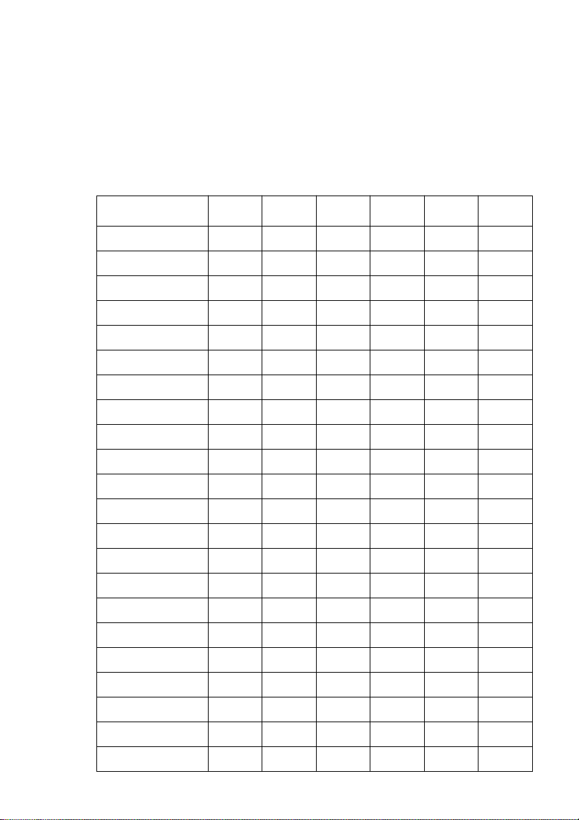
BANK C
Switches 1, 2: Print Mode
Turn these switches on or off to select the print mode you want to use.
Print Mode SW1 SW2
LQ ON ON
Draft OFF ON
Switches 3, 4, 5: Print Pitch
Turn these switches on or off to form the pattern that matches the print pitch
setting you want to make.
Print Pitch SW3 SW4 SW5
10cpi ON ON ON
12cpi OFF ON ON
15cpi ON OFF ON
17cpi OFF OFF ON
20cpi ON ON OFF
Proportional OFF ON OFF
Switch 6: Not used
Page 31

BANK D
EDS-1 Settings 25
Switches 1, 2, 3, 4: Page Length
Turn these switches on or off to form the pattern that matches the page length
setting you want to use.
Page Length SW1 SW2 SW3 SW4
11”/Letter ON ON ON ON
8” OFF ON ON ON
11.7”/A4 ON OFF ON ON
12” OFF OFF ON ON
8.5”/Letter ON ON OFF ON
14”/Legal OFF ON OFF ON
10.5”/Executive ON OFF OFF ON
7.25”/Executive OFF OFF OFF ON
3.5” ON ON ON OFF
5.5” OFF ON ON OFF
Switch 5: Cut-sheet eject direction
Specifies whether cut-sheet paper should be ejected towards the front of the
printer (ON) or towards the back (OFF).
Switch 6: Skew sensor for cut-sheet paper
Specifies whether the skew sensor for cut-sheet paper should be enabled (ON)
or disabled (OFF).
Page 32
26 Using the EDS Mode
BANK E
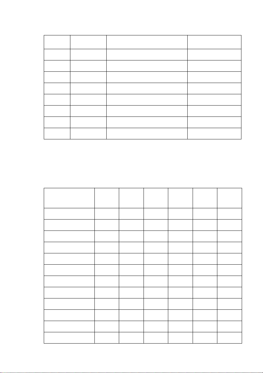
Switches 1, 2, 3, 4, 5, 6: Code Page/International Character Set
If your EDS settings specify IBM emulation (Bank A, Switch 1 OFF) with
either character table (Bank A, Switch 2), or Standard emulation (Bank A,
Switch 1 ON) with the graphics character table (Bank A, Switch 2 ON), use the
Bank E switches to select the default character code page you want to use.
Code Page SW1 SW2 SW3 SW4 SW5 SW6
#437 IBM-PC ON ON ON ON ON ON
#850 Multi-Lingual OFF ON ON ON ON ON
#860 Portuguese ON OFF ON ON ON ON
#861Icelandic OFF OFF ON ON ON ON
#863 Canadian French ON ON OFF ON ON ON
#865 Nordic OFF ON OFF ON ON ON
#866 Russian ON OFF OFF ON ON ON
#3840 IBM-Russian OFF OFF OFF ON ON ON
#3841 Gost-Russian ON ON ON OFF ON ON
#3843 Polish OFF ON ON OFF ON ON
#3844 CS2 ON OFF ON OFF ON ON
#3845 Hungarian OFF OFF ON OFF ON ON
#3846 Turkish ON ON OFF OFF ON ON
#3847 Brazil-ABNT OFF ON OFF OFF ON ON
#3848 Brazil-ABICOMP ON OFF OFF OFF ON ON
#852 Latin-2 OFF OFF OFF OFF ON ON
#1001 Arabic ON ON ON ON OFF ON
#737 Greek OFF ON ON ON OFF ON
#851 Greek ON OFF ON ON OFF ON
#869 Greek OFF OFF ON ON OFF ON
#928 Greek ON ON OFF ON OFF ON
#2001 Lithuanian-KBL OFF ON OFF ON OFF ON
Page 33
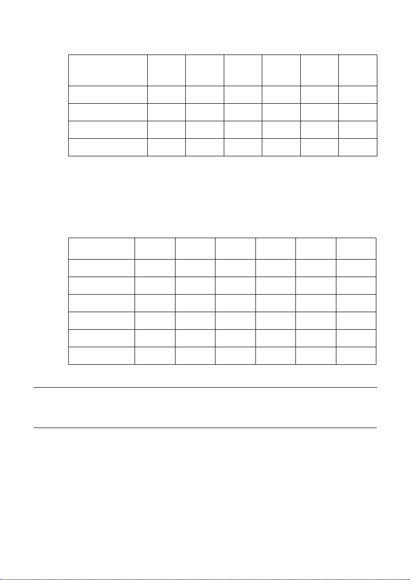
EDS-1 Settings 27
Code Page SW1 SW2 SW3 SW4 SW5 SW6
#772 Lithuanian ON OFF OFF ON OFF ON
#774 Lithuanian OFF OFF OFF ON OFF ON
#3001 Estonian-1 ON ON ON OFF OFF ON
#3002 Estonian-2 OFF ON ON OFF OFF ON
#3011 Latvian-1 ON OFF ON OFF OFF ON
#3012 Latvian-2 OFF OFF ON OFF OFF ON
#3021 Bulgarian ON ON OFF OFF OFF ON
#3031 Hebrew OFF ON OFF OFF OFF ON
#3041 Maltese ON OFF OFF OFF OFF ON
#3850 Standard KU OFF OFF OFF OFF OFF ON
#3860 Rajvitee KU ON ON ON ON ON OFF
#3861 Microwiz KU OFF ON ON ON ON OFF
#3863 STD 988 TIS ON OFF ON ON ON OFF
#3864 Popular TIS OFF OFF ON ON ON OFF
#3865 Newsic TIS ON ON OFF ON ON OFF
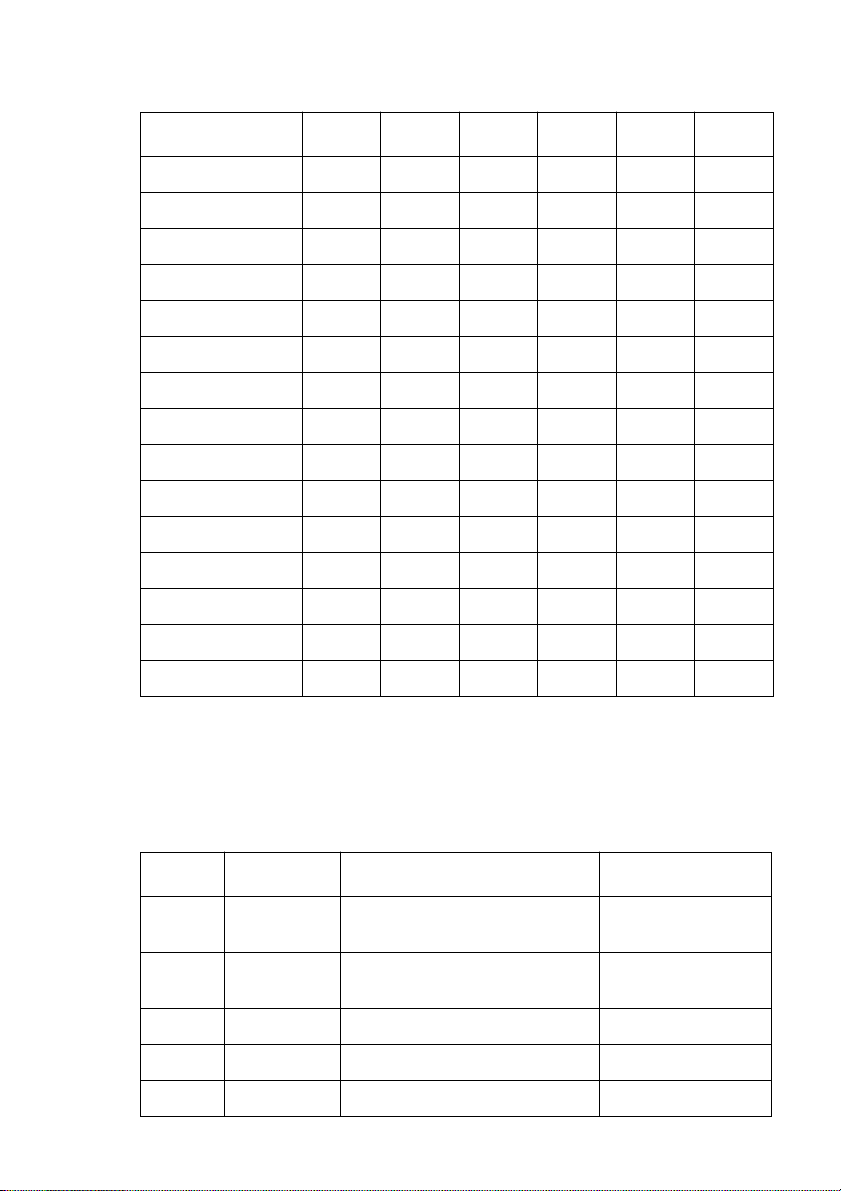
A code page is the set of symbols and characters that your printer can print.
Your printer converts ASCII hexadecimal data according to a code page to print
symbols and characters. By supporting different code pages, the printer can
print in a variety of different languages. The following table shows detailed
information about code pages.
Code Page Name Country Remarks
#437 IBM PC
#850 Multi-Lingual
#860 Portuguese Portugal
#861 Icelandic Iceland
#863 Canadian French Canada
United Kingdom, France, Germany, Italy,
Austria, Switzerland, United States, Spain
United Kingdom, France, germany, Italy,
Austria, Switzerland, United States, Spain
Preferred by Microsoft
Page 34
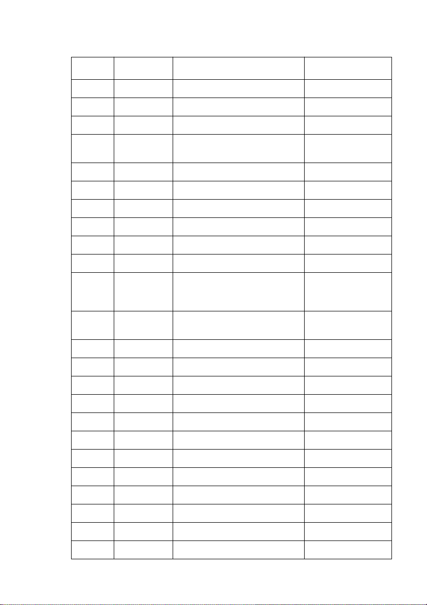
28 Using the EDS Mode
Code Page Name Country Remarks
#865 Nordic Denmark, Finland, Norway, Sweden Preferred by Microsoft
#866 Russian Russia Preferred by Microsoft
#3840 IBM-Russian Russia, Bulgaria
#3841 Gost-Russian
#3843 Polish Poland Also called “Mazovia”
#3844 CS2 Czech Republic Also called “Kamenicky”
#3845 Hungarian Hungary
#3846 Turkish Turkey
#3847 Brazil-ABNT
#3848 Brazil-ABICOMP
#852 Latin-2
#1001 Arabic
#737 Greek Greece Almost 80%
#851 Greek Greece
#869 Greek Greece
#928 Greek Greece For UNIX
#2001 Lithuanian-KBL Lithuania Commonly used for DOS
Russia Gost: government
standard
Croatia, Czech Republic, Hungary,
Poland, Romania, Serbia, Slovak
Republic, Slovenia
Egypt, Saudi Arabia Mainly in Arabic speaking
Preferred by Microsoft
countries
#772 Lithuanian Lithuania New standard
#774 Lithuanian Lithuania
#3001 Estonian-1 Estonia
#3002 Estonian-2 Estonia Most often used
#3011 Latvian-1 Latvia
#3012 Latvian-2 Latvia Government standard
#3021 Bulgarian Bulgaria
Page 35
EDS-1 Settings 29
Code Page Name Country Remarks
#3031 Hebrew Israel
#3041 Maltese Malta
#3850 Standard KU Thailand
#3860 Rajvitee KU Thailand
#3861 Microwiz KU Thailand
#3863 STD 988 TIS Thailand
#3864 Popular TIS Thailand
#3065 Newsic TIS Thailand
If your EDS settings specify Standard emulation (Bank A, Switch 1 ON) with
the italic character table (Bank A, Switch 2 OFF), use the Bank E switches to
select the international character set you want to use. This setting determines the
assignment of 14 character codes in the Standard Italic character set.
International
Character Set
U.S.A. ON ON ON ON ON ON
France OFF ON ON ON ON ON
Germany ON OFF ON ON ON ON
England OFF OFF ON ON ON ON
Denmark-1 ON ON OFF ON ON ON
Sweden OFF ON OFF ON ON ON
Italy ON OFF OFF ON ON ON
Spain-1 OFF OFF OFF ON ON ON
Japan ON ON ON OFF ON ON
Norway OFF ON ON OFF ON ON
Denmark-2 ON OFF ON OFF ON ON
Spain-2 OFF OFF ON OFF ON ON
SW1 SW2 SW3 SW4 SW5 SW6
Page 36
30 Using the EDS Mode
BANK F
International
Character Set
Latin America ON ON OFF OFF ON ON
Korea OFF ON OFF OFF ON ON
Ireland ON OFF OFF OFF ON ON
Legal OFF OFF OFF OFF ON ON
SW1 SW2 SW3 SW4 SW5 SW6
Switches 1, 2, 3, 4, 5, 6: LQ Font Selection
Turn these switches on or off to form the pattern that identifies the font you want
to use for LQ printing.
Font SW1 SW2 SW3 SW4 SW5 SW6
Roman ON ON ON ON ON ON
Sanserif OFF ON ON ON ON ON
Courier ON OFF ON ON ON ON
Prestige OFF OFF ON ON ON ON
OCR B OFF ON OFF ON ON ON
Note:
Orator OFF OFF OFF ON ON ON
Bank C switches 1 and 2 need to be in the correct positions before the above
setting will have any effect.
Page 37
EDS-2 Settings
The following details all of the settings you can make for EDS-2. For
communications protocol settings (Banks A and B), the matching settings you
have to make in your MS-DOS AUTOEXEC.BAT file.
BANK A
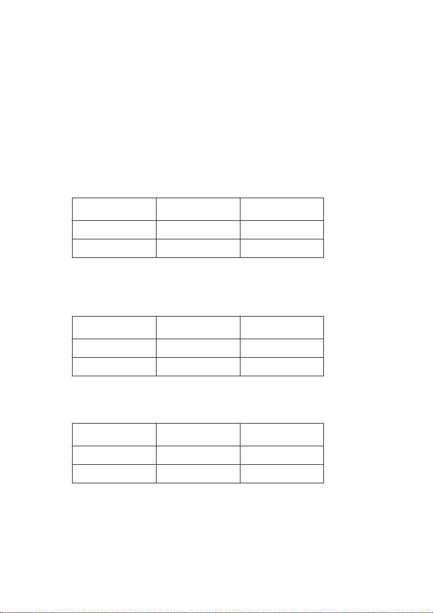
Switch 1: Data Length
Specifies the number of bits that the computer transmits as one byte. This setting
is normally 8.
Data Length SW1 DOS Setting
Switch 2: Parity Check
This switch specifies whether or not a parity check should be performed on the
data.
8 bits ON 8
7 bits OFF 7
EDS-2 Settings 31
Parity Check SW2 DOS Setting
Disabled ON Disabled
Enabled OFF Enabled
Switch 3: Parity
This switch specifies the parity as non, odd, or even.
Parity SW3 DOS Setting
Odd ON O
Even OFF E
Page 38
32 Using the EDS Mode
Switch 4: Protocol
Protocol, which is sometimes referred to as “handshaking,” is the
communications convention that is used to allow the printer and computer to
regulated the flow of data. DTR is the most commonly used protocol.
Protocol SW4 DOS Setting
DTR ON DTR
XON/XOFF OFF XON/XOFF
Switches 5, 6: Not used
BANK B
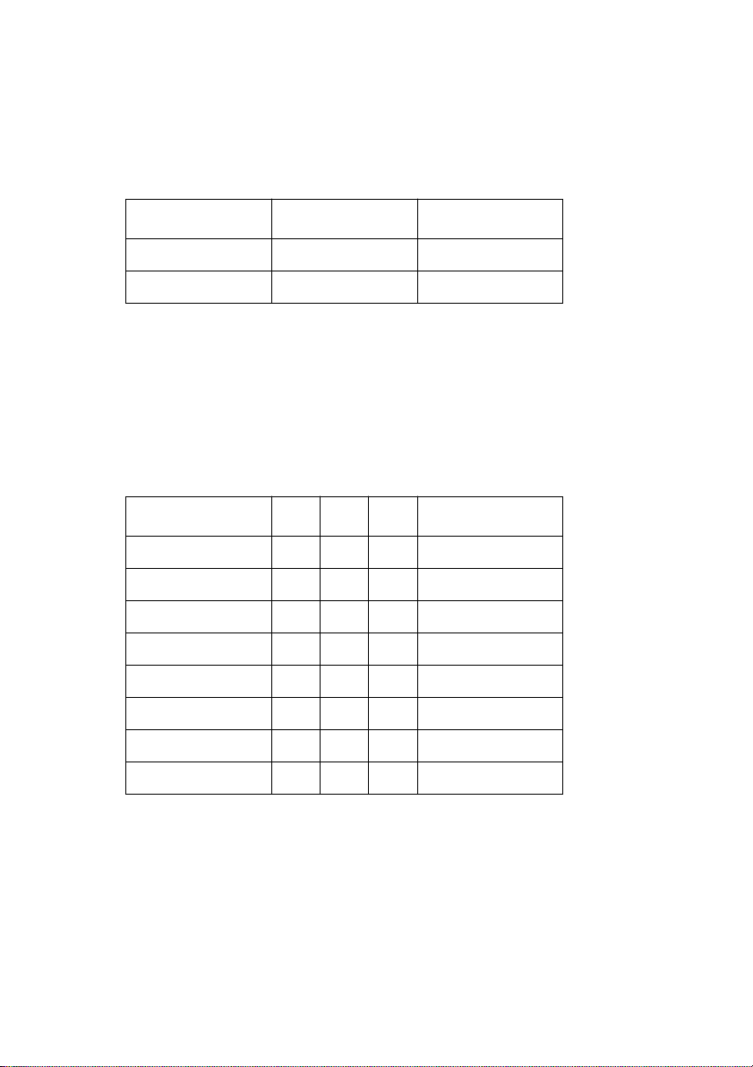
Switch 1, 2, 3: Baud Rate
The baud rate is the speed, in bits per second, that the printer sends data to the
computer. The common setting is 9600 or 19200.
Baud Rate SW1 SW2 SW3 DOS Setting
300 OFF OFF OFF 300
600 ON OFF OFF 600
1200 OFF ON OFF 1200
2400 ON ON OFF 2400
4800 OFF OFF ON 4800
9600 ON OFF ON 9600
19200 OFF ON ON 19200
9600 ON ON ON 9600
Switches 4, 5, 6: Not used
Page 39

BANK C
EDS-2 Settings 33
Switches 1, 2: Top and bottom margins
Use these switches to specify the top and bottom margins for printing.
Switch Setting Meaning
SW1
SW2
ON 1/6 ″ top margin for cut-sheet paper
OFF 0 ″ top margin for cut-sheet paper
ON 1/6 ″ bottom margin for cut-sheet paper
OFF 0 ″ bottom margin for cut-sheet paper
Switch 3: Head gap sensing for on each line
Specifies whether head gap sensing for on each line should be enabled (OFF) or
disabled (ON).
Switch 4: Control code FF
Control code FF (hexadecimal code 0C):
Specifies whether to eject paper (ON) or form feed (OFF).
Switches 5, 6: Waiting period for paper loading
Waiting Period SW5 SW6
2.0 seconds ON ON
1.5 seconds OFF ON
1.0 seconds ON OFF
0.5 seconds OFF OFF
Page 40
34
Chapter 4: Using the Printer with MS-DOS
This chapter contains information about how to use the printer with applications
software running under MS-DOS. In this chapter, you will learn about:
How to set up for printing with MS-DOS
❏
Setting up for printing with MS-DOS
To print from an application running under MS-DOS, you must first select the
printer from within the application. Typically, the program will feature an
INSTALL or SETUP command for selection of printers. Refer to the manual
for the application you are using for details on how to select a printer for it.
❏ Start up the application and use the correct procedure for that application to
select a printer. The following is a list of printers that can be used. If your
application lists more than one of these, select the printer that is nearest to
the top of this list. You should also use the EDS mode to select standard
emulation (page 22).
Star LC-8021
Star LC-8211
Star LC24-300/ NX-2480
LC24-30/NX-2450
Epson LQ-860/1060
Epson LQ-850/1050
If none of the printers listed above are available in the application, choose
one of the printers listed below. Once again, you should choose the printer
that is nearest to the top in the following list. For these printers, you should
use the EDS Mode to select IBM emulation (page 22).
IBM ProPrinter X24E/XL24E
IBM ProPrinter X24/XL24
❏ To print, follow the instructions given in the manual of the application you
are using. Typically, you would select the application’s PRINT command,
make any necessary changes in the window that appears (such as the
number of copies to be printed), and then press the Enter key to start
printing.
Page 41

Chapter 5: Paper Handling
This chapter tells you about the type of paper you can print on and how to feed
paper into the printer.
Selecting paper types
Use the following information when selecting paper.
Cut-Sheet Paper
Width: 3.0″ to 8.3″ / 76.2 to 210mm
Length: 2.5″ to 11.7″/63.5 to 297mm
Thickness: One-ply:
0.0028 to 0.0071″/0.07 to 0.18mm
Multi-ply:
0.0028 to 0.014″/0.07 to 0.35mm
Weight: One-ply:
14 to 42 lbs / 52 to 156g/m2 / 45 to 135 kg
Multi-ply:
11 to 14 lbs / 40 to 52g/m2 / 34 to 45 kg
35
Passbook
Width: 4.0″ to 6.0″ / 101.6 to 152.4mm
Length: 5″ to 8″/127.0 to 203.2mm (with the passbook opening)
Thickness: 2.0mm maximum (total thickness)
Number of Pages: 14 maximum (excluding cover)
Page 42

36 Paper Handling
Feeding a passbook into the printer
Use the following procedure to feed a passbook into the printer.
❏ Open the pass book to the page you want to print on.
❏ Check that the control panel’s POWER indicator is flashing, which shows
that there is no paper in the printer.
❏ Check to make sure that the control panel’s MULTI-PART indicator is not
lit. If it is, press the control panel’s MULTI-PART button.
❏ Insert the open passbook (top first) into the printer as far as it will go,
sliding its left side against the printer’s left guide.
Important!
If the passbook is not inserted straight into the printer, it will be considered a
loading error and the passbook will be ejected. Be sure to insert the passbook
correctly.
Inserting the passbook with its left side more than 7 mm to the right of the left
guide will be considered an error and the passbook will be ejected.
Pass book
Document table
The passbook will automatically be fed into the printer.
Control panel
❏ Start the printing operation from your software application.
❏ After the printing is complete, press EJECT to eject the passbook from the
printer.
Page 43

Feeding cut-sheet paper into the printer 37
Feeding cut-sheet paper into the printer
Use the following procedure to feed cut sheet paper into the printer.
When feeding large paper, such as A4-size paper, pull out the document table
extension.
❏ Check that the control panel’s POWER indicator is flashing, which shows
that there is no paper in the printer.
❏ When printing on 4-ply or 5-ply paper, the Multi-Part Mode should be
used. Check to make sure that the control panel’s MULTI-PART indicator
is lit. If it isn’t, press the control panel’s MULTI-PART button.
❏ Insert the paper into the printer as far as it will go, sliding its left side
against the printer’s left guide.
Important!
If the paper is not inserted straight into the printer, it will be considered a
loading error and the paper will be ejected. Be sure to insert the paper
correctly.
Inserting the paper with its left side more than 7 mm to the right of the left
guide will be considered an error and the paper will be ejected.
Paper
Document table extension
Document table
The paper will automatically be fed into the printer.
If your are using letterhead, make sure the paper is facing up, with the top
towards the printer.
Control panel
❏ Start the printing operation from your software application.
❏ After the printing is complete, press EJECT to eject the paper from the
printer.
Page 44

38 Paper Handling
Print area
The following shows the recommended print area for passbook and cut-
❏
sheet paper.
2.54 mm (0.1") 2.54 mm (0.1")
Pass book
Cut-sheet paper
4 mm (0.16")
10 mm (0.4")
*1
4 mm (0.16")
*1
4 mm (0.16")
10 mm (0.4")
Never allow printing to extend outside
*1
the print area, otherwise the print head
may be damaged.
2.54 mm (0.1")
2.54 mm (0.1")
2.3 mm (0.09")
Page 45

Chapter 6: Optional Accessories
This chapter explains how to install and use the following optional accessories
that are available for this printer:
❏ Serial Interface Unit (IS-NP192)
❏ Serial-to-Parallel Converter (SPC-8K)
Important!
Always make sure that printer power is turned off whenever installing or
removing optional accessories.
Serial Interface Unit (IS-NP192)
The parallel interface equipped on the printer as standard can be removed and
replaced with an optional IS-NP192 Serial Interface Unit. This makes it possible
to connect two separate computers for serial data communication.
39
Page 46

40 Optional Accessories
Serial-to-Parallel Interface Converter (SPC-8K)
Connecting the serial-to-parallel converter to the printer’s parallel connector
provides a second serial connection, which allows serial connections for two
separate computers.
Serial connector
Clear button
Parallel connector
Dip switch
Page 47

41
Appendix A: Troubleshooting
The appendix tells you what you need to know if you experience problems with
your printer. It tells you how to test the printer, how to check system software
settings, and how to adjust the vertical alignment. In addition, there is
information on actions to take for specific problems, and on the meanings of
printer beep tones.
Warning!
The printer uses high voltage. Do not attempt any other r epair or maintenance
except as expressly recommended in this appendix. Unauthorized repair and
maintenance not only exposes you to the danger of electrical shock, it also may
damage your printer and void your warranty.
Short test
Use the following procedure to test the printer to make sure that everything is
working correctly.
❏
Make sure that paper is loaded in the printer.
❏
Turn off the printer.
❏
While holding down ON LINE , turn on the printer.
The short test prints the version number of the software contained in the
printer’s ROM, followed by the current EDS settings of the printer.
❏
To stop printing, turn off the printer.
Long test
Use the following procedure to test the printer to make sure that everything is
working correctly.
❏
❏
❏
❏
Make sure that paper is loaded in the printer.
Turn off the printer.
While holding down LF , turn on the printer.
The long test prints a title followed by seven lines of text, and then continues
to print the entire character set for each font and pitch available.
To stop printing, turn off the printer.
Page 48

42 Troubleshooting
Note:
The test printing prints across the entire width of the carriage. Make sure that
the printer is loaded with the widest paper available in order to avoid damage
to the print head and platen.
Hexadecimal dump
This procedure prints in hexadecimal format all codes (character codes and
control codes) that are sent to the printer by the computer. The printer does not
execute any control codes (such as 0A - linefeed), it just prints them out. The
hexadecimal dump is useful when you are writing programs for printer control.
❏
Make sure that paper is loaded in the printer.
❏
Turn off the printer.
❏
While holding down MUL TI-PART and EJECT , turn the printer back on to
enter the Hex Dump Mode.
❏
To exit the Hex Dump Mode, turn the printer off.
Adjusting the dot alignment
You may never have to use the procedure described in this section, but after you
have been using your printer for some time you may find that the dots of some
graphics do not align correctly. For example, what should look like:
may come out looking like one of the following:
This is caused when mechanical parts of the printer get out of alignment. This
happens only rarely and you may never experience it at all throughout the life
of the printer. If you do have problems, use the following procedure to correct it.
❏
Make sure that paper is loaded in the printer.
❏
Turn off the printer.
or like this
Page 49

While holding down EJECT and ON LINE , turn the printer back on to
❏
enter the Dot Adjustment Mode.
The printer will print something like the following.
Adjusting the dot alignment 43
*** DOT ADJUSTMENT SETTING ***
Normal-density 0:
❏
If the two lines do not align properly , use MULTI-PART to move the lower
line to the left or EJECT to move it to the right.
The above step performs alignment for Normal-density mode only. You
must make separate adjustments for the CRT graphics mode I. DRAFT Text,
DRAFT Graphics, Double-density, CRT graphics mode II, Triple-density,
Quadruple-density, LQ Text and LQ Graphics modes as well.
❏
Press LF to change to another printing mode.
❏
Repeat the above steps for each printing mode, if necessary.
❏
After making changes to adjustments in all the printing modes you want,
press ON LINE to exit the Dot Adjustment Mode and register your
adjustments.
Important!
P erform the dot adjustment separately for the Normal Mode and the Multi-Part
Mode.
Page 50
44 Troubleshooting
Troubleshooting guide
Use the following table to help track down the causes of problems and to determine the
best solution to deal with them.
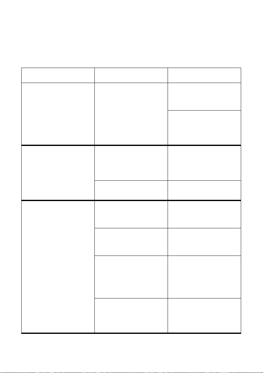
Problem Possible Cause Recommended Action
The ON LINE indicator does
not light.
Printer sounds like it is
printing, but it is not.
Printing is weak.
Printer test works, but printer
will not print out data from
the attached computer.
The printer is not receiving
power.
The ribbon is jammed,
twisted, or not set correctly
between the print head and
the print head shield.
The ribbon is worn out or
“used up.”
The wrong emulation is
selected
Y our application program’s or
system software’s printer
selection is wrong.
The computer’s system
software is not set up
properly for the printer or for
the port you are using.
Check whether the power
cord is correctly plugged into
the power outlet.
Check whether the power
outlet is working by
unplugging the printer and
plugging in another device.
Make sure that the ribbon
cartridge is installed
correctly.
Replace the ribbon with a
new one.
Check the emulation
selection and change it if
necessary. See page 22.
Check the printer selection
of your application software.
Check the system software
settings. Check the settings
for LPT1, COM 1, or COM 2
if you are using the Serial
Interface.
The interface cable is
connected incorrectly or
damaged.
Check to make sure that the
printer interface cable is
connected correctly. If it is,
try a different cable.
Page 51
Troubleshooting guide 45
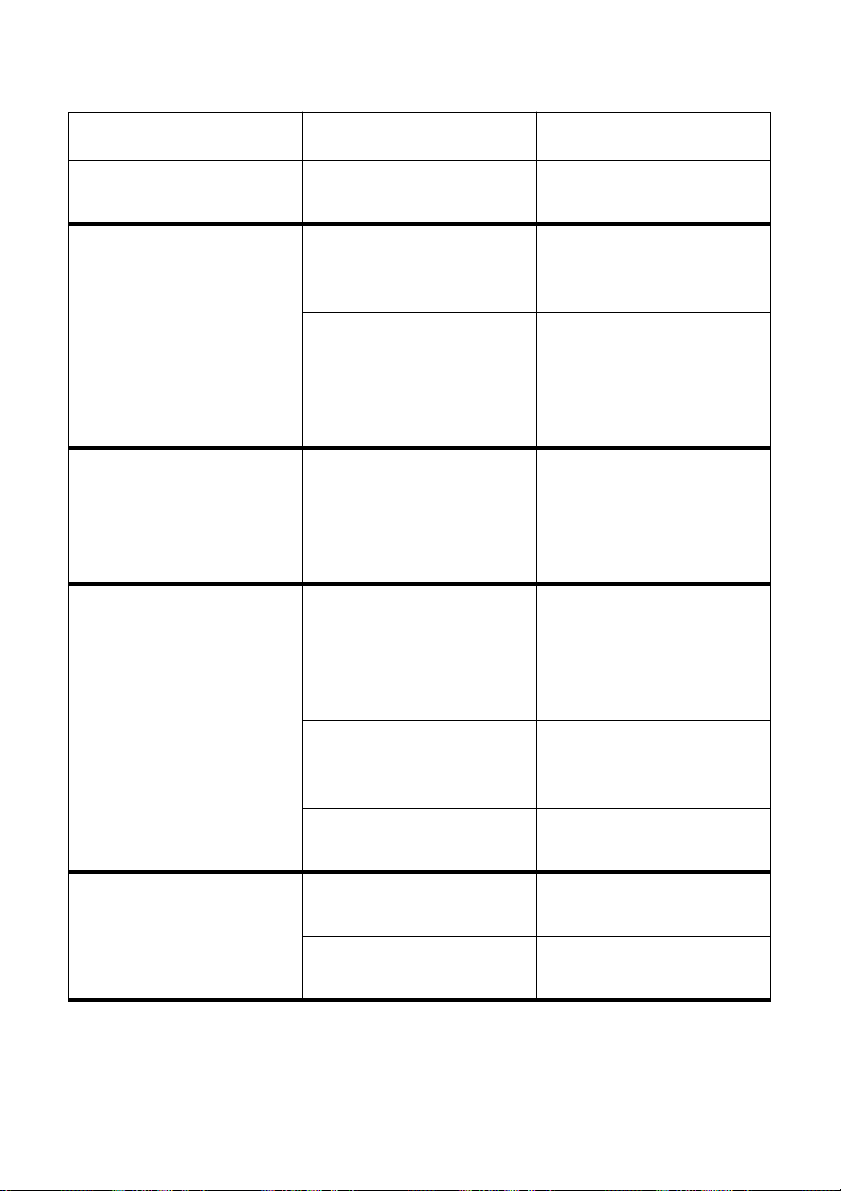
Problem Possible Cause Recommended Action
Printer does not feed paper
properly.
Line spacing is incorrect. The line spacing or leading
Lines print over each other. Auto line feed with carriage
Incorrect number of lines are
printed on the page.
Jamming paper. Remove all paper from the
selected in your application
program is wrong.
Auto line feed with carriage
return is enabled.
return is disabled.
Auto line feed with carriage
return is enabled.
The line spacing or leading
selected by your application
program is wrong.
printer and then reload it.
Choose a different line
spacing or leading setting
from your application.
Use the EDS Mode to
disable auto line feed with
carriage return. See “Switch
4: Auto LF with CR” on
page 23.
Use the EDS Mode to enable
auto line feed with carriage
return. See “Switch 4: Auto
LF with CR” on page 23.
Use the EDS Mode to
disable auto line feed with
carriage return. See “Switch
4: Auto LF with CR” on
page 23.
Choose a different line
spacing or leading setting
from your application.
Text and graphics are
malformed.
Print quality is poor.
Dot adjustment is not
correct.
The ribbon is worn out or
“used up.”
The print head is damaged. Return the printer to your
See “Adjusting the dot
alignment” on page 42.
Replace the ribbon with a
new one.
dealer for repair.
Page 52
46 Troubleshooting
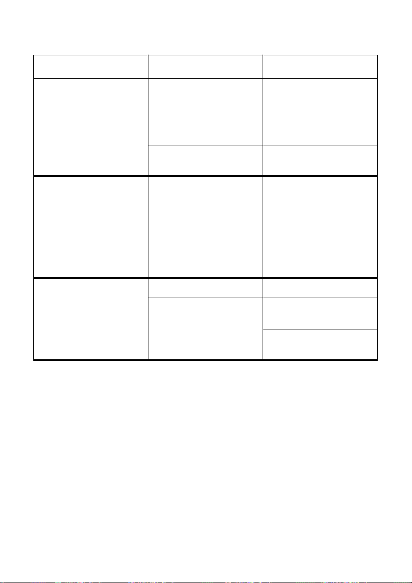
Problem Possible Cause Recommended Action
Forms are smudged.
Printing is too dark.
Printer case is hot. The printer’s air vents are
Printer makes excessive
noise.
The ribbon is jammed,
twisted, or not set correctly
between the print head and
the print head shield.
Print head shield is damaged
or missing.
blocked or obstructed.
The top cover is removed. Replace the top cover.
The printer is vibrating. Move any objects that are
Make sure that the ribbon
cartridge is installed
correctly . See “Removing the
protective materials” on
page 5.
Return it to your dealer for
repair.
Switch off the printer and let
it cool. Check the air vents
on the bottom of the printer
to see if they are blocked.
Remove the obstruction if
possible. If the problem
persists, return the printer to
your dealer for repair.
touching the printer.
Make sure that the printer is
on a level steady surface.
Page 53
Troubleshooting guide 47
Problem Possible Cause Recommended Action
Printer prints past the edge
of the paper.
Left margin moves to the
right during printing.
Incorrect margin settings
are selected by your
application program.
The paper guide is not
positioned correctly.
The ribbon is jammed,
causing the print head to
jam.
Paper is jamming, causing
the print head to jam.
The paper is not loaded
correctly, causing the print
head to jam.
The ribbon cartridge is not
installed correctly, causing
the print head to jam.
Choose different margin
settings from your
application program.
Remove the paper and
adjust the position of the
paper guide. Reload the
paper and try printing again.
Make sure that the ribbon
cartridge is installed
correctly . See “Removing the
protective materials” on
page 5.
Remove all paper from the
printer and reload it. Try
printing again.
Remove all paper from the
printer and reload it. Try
printing again.
Make sure that the ribbon
cartridge is installed
correctly . See “Removing the
protective materials” on
page 5.
Inappropriate settings are
selected by your application
program.
Static electricity caused by
interference from nearby
electrical devices or by lowlevel humidity is affecting
printer operation.
Choose different settings in
your application.
Make sure that the printer is
not too close to any devices
with electric motors or that
raise the humidity level.
Page 54
48 Troubleshooting
Problem Possible Cause Recommended Action
Some characters are printed
incorrectly .
Printer behaves erratically.
Printing suddenly stops.
The wrong emulation is
selected
The wrong character table,
code page, or international
character set is selected.
Static electricity caused by
interference from nearby
electrical devices or by lowlevel humidity is affecting
printer operation.
Inappropriate settings are
selected by your application
program.
Wires are missing from the
print head.
The interface cable is
connected incorrectly or
damaged.
Check the emulation
selection and change it if
necessary. See page 22.
Use the EDS Mode to select
the correct character table,
code page, or international
character set (page 26).
Make sure that the printer is
not too close to any devices
with electric motors or that
raise the humidity level.
Choose different settings in
your application.
Return the printer to your
dealer for repair.
Check to make sure that the
printer interface cable is
connected correctly. If it is,
try a different cable.
Static electricity caused by
interference from nearby
electrical devices or by lowlevel humidity is affecting
printer operation.
Make sure that the printer is
not too close to any devices
with electric motors or that
raise the humidity level.
Page 55

Checking system software settings in MS-DOS 49
Checking system software settings in MS-DOS
If you are using a parallel cable and cannot print a text file using the MS-DOS
PRINT command, you may have a problem with your AUTOEXEC.BAT file.
Open the file and look for the following line:
MODE LPT1:=COM 1 or MODE LPT1:=COM 2
These lines indicate you are using a serial cable connection, and so you should
delete them, save the AUTOEXEC.BAT file, reboot and try printing again.
Of course, if you are having problems printing with the optional serial-toparallel converter, you should conversely check to make sure that one of the
above lines is included in your AUTOEXEC.BAT file. The file must also
contain information on parameter settings. For details, see the user’s manual
that comes with the optional Serial-to-Parallel Interface Converter.
If the above is not the problem or if you make the above changes and still
experience problems printing using the MS-DOS PRINT command, refer to
your MS-DOS Users’ Guide or consult your software dealer.
If you are successful in printing using the MS-DOS PRINT command but
cannot print from an application, check to see what printer driver is selected in
the application. See “Setting up for printing with MS-DOS” on page 34. If this
does not help, consult your software dealer.
Page 56

50
Appendix B: Specifications
Printing System
Printing Speed Pitch Draft (cps/dpi) LQ (cps/dpi)
Print Direction
Print Head
Line Spacing
Character Matrix Pitch Draft (cps/dpi) LQ (cps/dpi)
Environment Operating temperature: 41°F to 95°F (5°C to 35°C)
Serial Impact Dot-Matrix
Pica (10 cpi) 250/120H 83/360H
Elite (12 cpi) 300/120H 100/360H
Semi-condensed (15 cpi(S)) 375/120H 125/360H
Semi-condensed (15 cpi (I)) 150/240H 125/360H
Condensed pica (17 cpi) 171/240H 142/360H
Condensed elite (20 cpi) 200/240H 166/360H
24 cpi (I) 240/240H 200/360H
H: half-dot
(S): Standard mode only
(i): IBM mode only
Draft: Uni-directional/ bi-directional logic seeking (selectable)
LQ: Uni-directional/ bi-directional logic seeking (selectable)
Bit-Image: Uni-directional/ bi-directional logic seeking (selectable)
Number of pins: 24
Life: 200 million dots/pin (Normal Mode)
100 million dots/pin (Multi-Part Mode)
1/6 ″ , 1/8 ″
7/60 ″ , 7/72 ″ , n /72 ″ , n /180 ″ , n /216 ″ , n /360 ″ : software
Pica (10 cpi) 24 × 9H 24 × 31H
Elite (12 cpi) 24 × 9H 24
Semi-condensed (15 cpi(S)) 16 × 7H 16 × 21H
Semi-condensed (15 cpi (I)) 24 × 9H 24 × 16H
Condensed pica (17 cpi) 24 × 9H 24 × 16H
Condensed elite (20 cpi) 24 × 9H 24 × 16H
24 cpi (I) 24 × 9H 24 × 14H
H: half-dot
(S): Standard mode only
(i): IBM mode only
Storage temperature: -22°F to 149°F (-30°C to 65°C)
Operating humidity: 30% to 80% (non-condensing)
Storage humidity: 20% to 90% (non-condensing)
×
27H
Page 57

51
Paper Cut-sheet
Paper width: 3″ to 8.3″ / 76.2 to 210 mm
Paper length: 2.5″ to 11.7″ / 63.5 to 297 mm
Paper thickness: 0.0028″ to 0.0071″ / 0.07 to 0.18 mm (1-ply)
0.0028″ to 0.014″ / 0.07 to 0.35 mm (multi-ply)
Paper weight: 14 to 42 lbs. / 52 to 156 g/m2 / 45 to 135 kg (1-ply)
11 to 14 lbs. / 40 to 52 g/m2 / 34 to 45 kg (multi-ply)
Copy capability Normal mode:
Original + 0-2 copies (Total thickness: Max. 0.25 mm)
Multi-part mode:
Original + 3-4 copies (Total thickness: Max. 0.35 mm)
Pass book
Paper width: 4″ to 6″ / 101.6 to 152.4 mm
Paper length:
Total paper thickness: 2 mm (max.)
Number of pages: 14 excluding cover
Emulation Standard Mode: EPSON ESC/P (24-pin)
NEC Graphic Compatible
IBM Mode: Proprinter XL24E
Interfaces Standard: Centronics parallel and RS-232 (dual interface)
Option: Dual serial interface
Ribbon Type On-carriage, dedicated
Monochrome: Black only
P24 (Standard)
Ribbon Life P24: 2 million characters (ASCII draft)
Dimensions and Weight Width: 16.1″ / 410 mm
Depth: 12.6″ / 320 mm
Height: 7.66″ / 194.5 mm
Weight: 18.94 lbs. / 8.6 kg
Power Supply 220V AC ±10%; 50/60Hz
Power Consumption 13W during stand-by
55W during ASCII draft printing
Options SPC-8K Serial-To-Parallel Converter
IS-NP192 Serial Interface Unit
P24 Refill Ribbon
″
to 8″ / 127 to 203.2 mm
5
Page 58

52
Appendix C: Interface Pin Outs
Parallel Interface
Pin Name Function
1 STROBE Goes low for ≥0.5µs when active.
2 DATA0 These signals represent information for the 1st through 8th bit of parallel data,
3 DATA1
4 DATA2
5 DATA3
6 DATA4
7 DATA5
8 DATA6
9 DATA7
10 ACK
11 BUSY Printer sets line low when ready to receive data.
12 PAPER High when paper runs out.
13 SELECT High when printer is on-line.
14 AFXT Printer ignores this signal.
15 Not used.
16 SIGNAL GND Signal ground
17 CHASSIS Chassis ground (isolated from signal ground)
18 +5V +5V DC output from printer
19 - 30 GND Twisted pair ground return
31 RESET Printer is reset when this signal goes low.
32 ERROR Low when printing cannot continue due to error.
33 EXT GND External ground
34 - 35 Not used
36 SELECT IN Printer ignores this signal
respectively. Each signal is HIGH when data is logical 1, and LOW when logical
0.
10µs low to acknowledge receipt of data.
Serial Interface
Pin Name Function
1 CHASSIS Printer chassis ground
2 TXD Data from printer
3 RXD Data to printer
4 RTS Always space
5 CTS Space when computer is ready to send data. Printer ignores this signal.
6 Not used.
7 GND Signal ground
8 - 10 Not used.
11 RCH Printer sets line to space when ready to receive data. Same signal as Pin 20.
12 Not used.
13 Not used. (signal ground)
14 - 19 Not used.
20 DTR Printer sets line to space when ready to receive data.
21 - 25 Not used.
Page 59
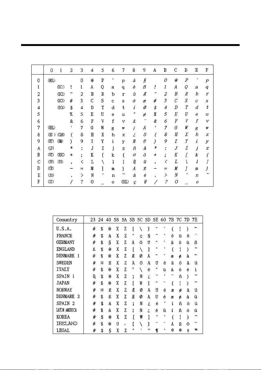
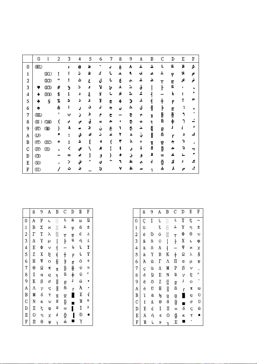
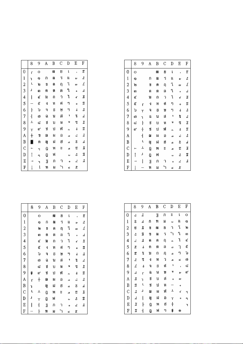
Appendix D: Character Sets
Standard Italic Character Set
53
International Character Set
The character codes shown in the table are hexadecimal.
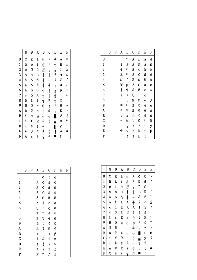
Page 60

54 Character Sets
IBM Character Set #2
Code Page #437 (IBM-PC)
IBM Character Set #1
Other characters are the same as those for Character Set #2.
Page 61

55
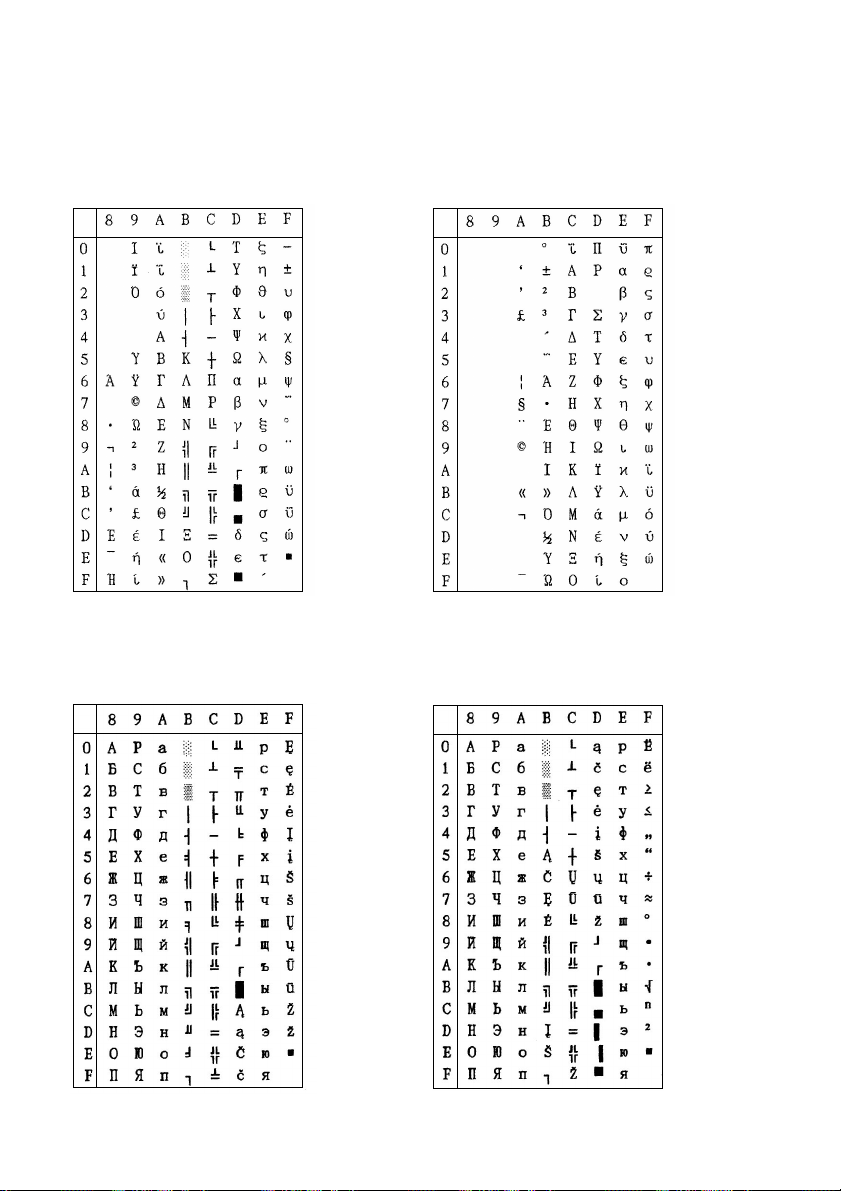
IBM Special Character Set
The following characters can be printed
using the <ESC> ^ command.
Code Page #860
Portuguese
Other characters are the same as those for
Code Page #437.
Code Page #850
Multi-lingual
Other characters are the same as those for
Code Page #437.
Code Page #861
Icelandic
Other characters are the same as those for
Code Page #437.
Page 62

56 Character Sets
Code Page #863
Canadian French
Other characters are the same as those for
Code Page #437.
Code Page #866
Russian
Other characters are the same as those for
Code Page #437.
Code Page #865
Nordic
Other characters are the same as those for
Code Page #437.
Code Page #3840
IBM-Russian
Other characters are the same as those for
Code Page #437.
Page 63

57
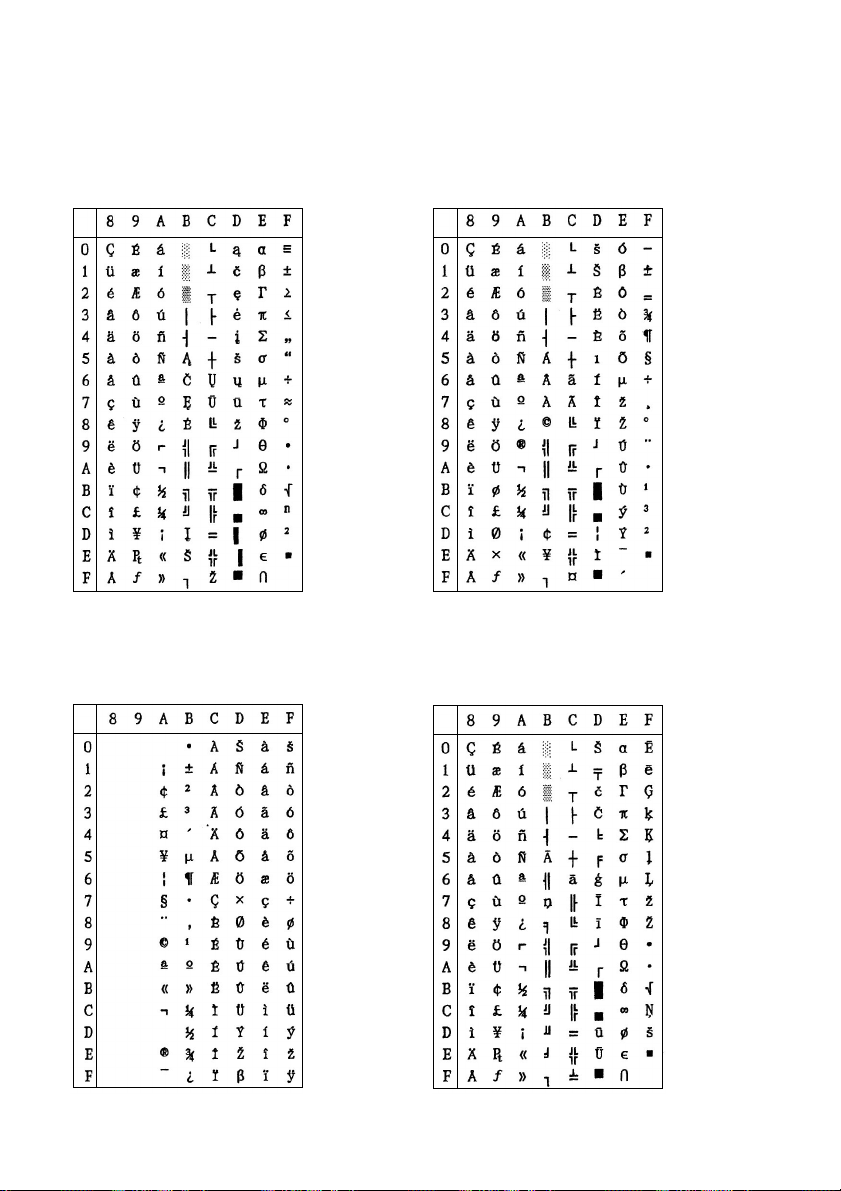
Code Page #3841
Gost-Russian
Other characters are the same as those for
Code Page #437.
Code Page #3844
CS2
Other characters are the same as those for
Code Page #437.
Code Page #3843
Polish
Other characters are the same as those for
Code Page #437.
Code Page #3845
Hungarian
Other characters are the same as those for
Code Page #437.
Page 64
58 Character Sets
Code Page #3846
Turkish
Other characters are the same as those for
Code Page #437.
Code Page #3848
Brazil-ABICOMP
The other characters are the same as in
code page #437.
Code Page #3847
Brazil-ABNT
Other characters are the same as those for
Code Page #437.
Code Page #852
Latin-2
Other characters are the same as those for
Code Page #437.
Page 65
Code Page #1001
Arabic
59
Code Page #737
Greek
Other characters are the same as those for
Code Page #437.
Code Page #851
Greek
Other characters are the same as those for
Code Page #437.
Page 66
60 Character Sets
Code Page #869
Greek
Other characters are the same as those for
Code Page #437.
Code Page #2001
Lithuanian-KBL
Other characters are the same as those for
Code Page #437.
Code Page #928
Greek
Other characters are the same as those for
Code Page #437.
Code Page #772
Lithuanian
Other characters are the same as those for
Code Page #437.
Page 67
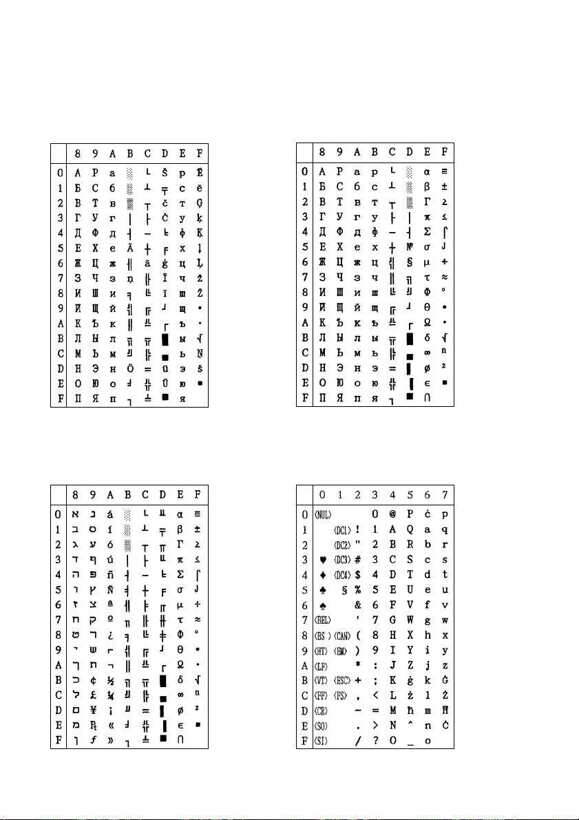
61
Code Page #774
Lithuanian
Other characters are the same as those for
Code Page #437.
Code Page #3002
Estonian2
Other characters are the same as those for
Code Page #437.
Code Page #3001
Estonian1
Other characters are the same as those for
Code Page #437.
Code Page #3011
Latvian1
Other characters are the same as those for
Code Page #437.
Page 68
62 Character Sets
Code Page #3012
Latvian2
Other characters are the same as those for
Code Page #437.
Code Page #3031
Hebrew
Other characters are the same as those for
Code Page #437.
Code Page #3021
Bulgarian
Other characters are the same as those for
Code Page #437.
Code Page #3041
Maltese
Other characters are the same as those for
Code Page #437.
Page 69
63
Code Page #3850
Standard KU
Other characters are the same as those for
Code Page #437.
Code Page #3861
Microwiz KU
Other characters are the same as those for
Code Page #437.
Code Page #3860
Rajvitee KU
Other characters are the same as those for
Code Page #437.
Code Page #3863
STD988 TIS
Other characters are the same as those for
Code Page #437.
Page 70
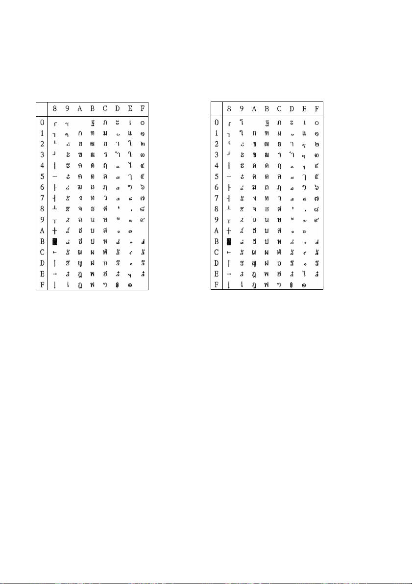
64 Character Sets
Code Page #3864
Popular TIS
Other characters are the same as those for
Code Page #437.
Code Page #3865
Newsic TIS
Other characters are the same as those for
Code Page #437.
Page 71
BS
HT
LF
VT
FF
CR
SO
SI
Appendix E: Printer Control Codes
This appendix lists the printer’s control commands. It gives the name of each control
command, along with the applicable emulation mode (Standard or IBM), and the
applicable ASCII code.
Standard Mode
ASCII Code Function
BEL
DC1
DC2
DC3
DC4
CAN
ESC LF
ESC FF
ESC SO
ESC SI
ESC EM
ESC SP
ESC !
n
=00
ESC #
ESC $
n
n
01
02
04
08
10
20
40
80
n
n
L
H
Beeper
Backspace
Tab horizontally
Line feed
Tab vertically
Form feed
Carriage return
Select double width printing (1 line)
Select condensed printing
Select printer
Cancel condensed printing
Deselect printer
Cancel double width printing (1 line)
Cancel line
Reverse feed by current line space
Reverse form feed
Select double width printing (1 line)
Select condensed printing
Control cut-sheet feeder (printer ignores this code)
Set inter character space
Master select
10 cpi (ESC P)
12 cpi (ESC M)
Proportional (ESC p)
Condensed (SI)
Emphasised (ESC E)
Double-strike (ESC G)
Double-wide expanded (ESC W)
Italic (ESC 4)
Underlining (ESC -)
Cancel MSB control
Set absolute horizontal print position
65
Page 72
66 Printer Control Codes
Standard Mode
ASCII Code Function
ESC %
n
n
=00
01
ESC & 00
ESC (-
d1 =01
d2 =00
ESC (B
ESC (^
ESC (t 03 00 d1 d2 00
d1 = ESC t d1
d2 =00
ESC * m
ESC + n
ESC - n
ESC / m
d
...d
1
n
02
03
01
02
05
06
n
c d
k = 00
01
02
03
04
05
06
07
n
01
03
07
19
08
09
1A
1B
1C
1D
1E
1F
20
21
22
18
n
=00
01
n
m a
1
k
m d1 d
n
L
H
n
k m s v1 v2
1
2
n
L
H d1
n
n
L
H d1
a
...d
...d
a
2
3
2
k
k
Select user defined characters
Normal (ROM) characters
User-defined (RAM) characters
Define user defined characters
Select line/score
Underline
Strikethrough
Overscore
Turn off scoring
Single continuous line
Double continuous line
Single broken line
Double broken line
Bar-code
EAN-13
EAN-8
Interleaved 2 of 5
UPC-A
UPC-E
CODE39
CODE128
Postnet
Print data as characters
Assign character table
#437 USA
#850 Multi-lingual
#860 Portuguese
#861 Icelandic
#863 Canadian French
#865 Nordic
#866 Russian
#3840 IBM-Russian
#3841 Gost
#3843 Polish
#3844 CS2
#3745 Hungarian
#3846 Turkish
#3847 Brazil-ABNT
#3848 Brazil-ABICOMP
#852 Latin-2
Select bit-image
Set n/360″ line spacing
Turn under line on/off
Turns underline off
Turns underline on
Select vertical tab channel
Italic
Page 73
Standard Mode
ASCII Code Function
ESC 0
ESC 2
ESC 3 n
ESC 4
ESC 5
ESC 6
ESC 7
ESC 8
ESC 9
ESC <
ESC =
ESC >
ESC ? n m
ESC @
ESC A n
ESC B d1...dk 00
ESC C n
ESC C 0 n
ESC D
n
...
n
00
1
k
ESC E
ESC F
ESC G
ESC H
ESC J n
ESC K
n
n
L
H d1
ESC L
n
n
L
H d1
ESC M
ESC N n
ESC O
ESC P
ESC Q n
...d
...d
67
Select 1/8″ line spacing
Select 1/6″ line spacing
Select n/180″ line spacing
Select italic font
Cancel italic font
Enable printing of upper control codes (Character Set #2)
Enable upper control codes (Character Set #1)
Disable paper out detector
Enable paper out detector
Unidirectional mode (1 line)
Set MSB to 0
Set MSB to 1
Reassign bit-image mode
Initialise printer
Set n/60″ line spacing
Set vertical tab
Set page length in lines
Set page length in inches
Set horizontal tab
Select bold font
Cancel bold font
Select double strike printing
Cancel double strike printing
Advance print position vertically
k
k
Select 60 dpi graphics
Select 120 dpi graphics
Select elite pitch
Set bottom margin
Cancel bottom margin
Select pica pitch
Set right margin
Page 74

68 Printer Control Codes
Standard Mode
ASCII Code Function
ESC R n
n
=00
01
02
03
04
05
06
07
08
09
0A
0B
0C
0D
0E
40
ESC S n
n
=00
01
ESC T
ESC U n
n
=00
01
ESC W n
n
=00
01
ESC Y
n
n
...d
L
ESC Z
H d1
n
n
L
H d1
...d
k
k
Select an international character set
#0 U.S.A.
#1 France
#2 Germany
#3 England
#4 Denmark I
#5 Sweden
#6 Italy
#7 Spain I
#8 Japan
#9 Norway
#10 Denmark II
#11 Spain II
#12 Latin America
#13 Korea
#14 Irish
#64 Legal
Select superscript/subscript printing
Superscript
Subscript
Cancel superscript/subscript printing
Turn unidirectional mode on/off
Unidirectional
Bi-directional
Turn double width printing on/off
Turns off double-width
Turns on double-width
Select 120 dpi double speed graphics
Select 240 dpi graphics
Page 75

Standard Mode
ASCII Code Function
ESC [T 04 00 00 00
n
n
= 01 B5
1
2
03 52
03 5C
03 5D
03 5F
03 61
03 62
0F 00
0F 01
0F 03
0F 04
0F 05
0F 06
0F 07
0F 08
03 54
03 E9
02 E1
03 53
03 65
03 A0
07 D1
03 04
03 06
0B B9
0B BA
0B C3
0B C4
0B CD
0B D7
0B E1
0F 0A
0F 14
0F 15
0F 17
0F 18
0F 19
ESC \
n
n
L
H
ESC b m
ESC g
ESC h n
ESC j n
ESC k n
n
=00
n
=00
01
02
01
02
03
05
07
n
...
n
00
1
k
n
n
Select code page
1
2
#437 USA
#850 Multi-lingual
#860 Portuguese
#861 Icelandic
#863 Canadian French
#865 Nordic
#866 Russian
#3840 IBM-Russian
#3841 Gost
#3843 Polish
#3844 CS2
#3845 Hungarian
#3846 Turkish
#3847 Brazil-ABNT
#3848 Brazil-ABICOMP
#852 Latin-2
#1001 Arabic
#737 Greek #737
#851 Greek #851
#869 Greek #869
#928 Greek #928
#2001 Lithuanian-KBL
#772 Lithuanian #772
#774 Lithuanian #774
#3001 Estonian-1
#3002 Estonian-2
#3011 Latvian-1
#3012 Latvian-2
#3021 Bulgarian
#3031 Hebrew
#3041 Maltese
#3850 Standard KU
#3860 Rajvitee KU
#3861 Microwiz KU
#3863 STD 988 TIS
#3864 Popular TIS
#3865 Newsic TIS
Move relative horizontal print position
Set vertical tab in VFU channels
Select semi-condensed pitch
Select 1×1, 2×2, 4×4 sized printing
Cancels enlargement
Select double-high, double-wide (2×2)
Select quadruple-high, quadruple-wide (4
Advance reverse feed
Select typeface
Roman
Sanserif
Courier
Prestige
OCR-B
Orator
69
×
4)
Page 76

70 Printer Control Codes
Standard Mode
ASCII Code Function
ESC l
ESC p
n
ESC q
n
ESC t
n
ESC w
n
ESC x
n
FS 3
FS @
FS C
n
FS E
n
FS F
FS I
n
FS R
FS V
n
FS Z
FS \
FS ^
DEL
n
n
=00
01
n
=00
01
02
03
n
=00
01
02
n
=00
01
n
=00
01
n
n
=00
01
02
03
05
07
n
=00
01
02
n
=00
01
02
n
=00
01
n
n
L
n
n
L
d
...d
H
1
k
H
Set left margin
Turn proportional mode on/off
Returns to current fixed character pitch
Selects proportional spacing
Select character style
Cancel shadow/outline printing
Set outline printing
Set shadow printing
Set shadow & outline printing
Select character table
Select italic character table
Select code page table set by EDS Setting
Set download character in “00H-7FH” to “80H-FFH”
Turn double high printing on/off
Turns on double-width
Turns off double-width
Select LQ or Draft
Draft
LQ
Set line spacing to
n
/360 ″
Initialise printer
Select typeface
Roman
Sanserif
Courier
Prestige
OCR-B
Orator
Select double, triple width printing
Cancel expanded print (ESC W 0)
Select double-wide print (ESC W 1)
Select triple-wide print
Select forward feed
Select character table
Select standard character table
Select IBM character table
Set characters downloaded in “00h-7Fh” area to “80h-FFh” area
Select reverse feed
Turn double high printing on/off
Cancel double-high mode
Select double-high mode
Select 360 dpi graphics
Print characters from all character chart
Print a character from all character chart
Delete last character in buffer
Page 77

IBM Mode
ASCII Code Function
BEL
BS
HT
LF
VT
FF
CR
SO
SI
DC1
DC2
DC4
CAN
ESC - n
n
=00
01
ESC 0
ESC 1
ESC 2
ESC 3 n
ESC 4
ESC 5 n
n
=00
01
ESC 6
ESC 7
ESC :
ESC A n
ESC B
n
1
ESC C n
ESC C 0 n
ESC D
n
1
ESC E
ESC F
ESC G
...
...
71
Beeper
Backspace
Tab horizontally
Line feed
Tab vertically
Form feed
Carriage return
Select double width printing (1 line)
Select condensed printing
Select printer
Select pica pitch
Cancel double width printing (1 line)
Cancel line
Turn under line on/off
Select 1/8″ line spacing
Select 7/72″ line spacing
Execute “ESC A” definition
Select n/216″ or n/180″ or n/360″ line spacing
Set top of form to the current position
Turn automatic line feed on/off
Enable printing of upper control codes (Character Set #2)
Enable upper control codes (Character Set #1)
Select elite pitch
Define line spacing to n/72
n
k
00
Set vertical tab
Set page length in lines
Set page length in inches
n
k
00
Set horizontal tab
Select bold font
Cancel bold font
Select double strike printing
Cancel underlining
Select underlining
Automatic line feeding stops
Automatic line feeding starts
″
Page 78

72 Printer Control Codes
IBM Mode
ASCII Code Function
ESC H
ESC I n
n
=00
08
10
02
0A
12
03
04
0C
14
06
0E
16
07
ESC J n
ESC K
n
n
...d
L
ESC L
n
ESC N n
ESC O
ESC P n
n
=00
ESC Q n
ESC R
ESC S n
n
=00
ESC T
ESC U n
n
=00
ESC W n
n
=00
ESC X
n
ESC Y
n
ESC Z
n
ESC [@
ESC [K
p
2
H d1
n
L
H d1
01
01
01
01
n
L
H
n
L
H d1
n
L
H d1
n
n
L
n
n
L
H
k
...d
k
...d
k
...d
k
...m
H m1
k
init id p1
Cancel double strike printing
Select print pitch and download
Resident draft pica
Resident draft elite
Resident draft condensed
Default LQ pica
Default LQ elite
Default LQ condensed
Default LQ proportional
Download draft pica
Download draft elite
Download draft condensed
Download LQ pica
Download LQ elite
Download LQ condensed
Download LQ proportional
Advance print position vertically n/180″ or n/216″ or n/360″
Select 60 dpi graphics
Select 120 dpi graphics
Set bottom margin
Cancel bottom margin
Turn proportional mode on/off
Cancel proportional printing
Select proportional printing
Deselect printer
Set all tabs to power on defaults
Select superscript/subscript printing
Select Superscript
Select Subscript
Cancel superscript/subscript printing
Turn unidirectional mode on/off
Select bi-directional mode
Select unidirectional mode
Turn double width printing on/off
Cancel expanded print
Select expanded print
Set left and right margins
Select 120 dpi double speed graphics
Select 240 dpi graphics
Control width, high and line spacing
Set initial condition
Page 79

IBM Mode
ASCII Code Function
ESC [T 04 00 00 00
n
n
= 01 B5
1
2
03 52
03 5C
03 5D
03 5F
03 61
03 62
0F 00
0F 01
0F 03
0F 04
0F 05
0F 06
0F 07
0F 08
03 54
03 E9
02 E1
03 53
03 65
03 A0
07 D1
03 04
03 06
0B B9
0B BA
0B C3
0B C4
0B CD
0B D7
0B E1
0F 0A
0F 14
0F 15
0F 17
0F 18
0F 19
ESC [\
ESC [g
ESC \
ESC ]
ESC ^
ESC _ n
ESC d
ESC j
n
=00
n
n
L
H m1 m2 m3 m4
n
n
m d1...dkSelect graphic mode
L
H
n
n
L
H
01
n
n
L
H
n
n
Select code page
1
2
#437 USA
#850 Multi-lingual
#860 Portuguese
#861 Icelandic
#863 Canadian French
#865 Nordic
#866 Russian
#3840 IBM-Russian
#3841 Gost
#3843 Polish
#3844 CS2
#3845 Hungarian
#3846 Turkish
#3847 Brazil-ABNT
#3848 Brazil-ABICOMP
#852 Latin-2
#1001 Arabic
#737 Greek #737
#851 Greek #851
#869 Greek #869
#928 Greek #928
#2001 Lithuanian-KBL
#772 Lithuanian #772
#774 Lithuanian #774
#3001 Estonian-1
#3002 Estonian-2
#3011 Latvian-1
#3012 Latvian-2
#3021 Bulgarian
#3031 Hebrew
#3041 Maltese
#3850 Standard KU
#3860 Rajvitee KU
#3861 Microwiz KU
#3863 STD 988 TIS
#3864 Popular TIS
#3865 Newsic TIS
Set base unit of line spacing
Print characters from all character chart
Reverse line feed
Print a character from all character chart
Turn over-score on/off
Cancel overscoring
Select overscoring
Move print position to the right
Stop printing
73
Page 80

74
Appendix F: Glossary
Centronics cable
Parallel cable normally used to connect the printer to the computer.
control code
A numeric code that instructs the printer to perform an operation. For example,
the computer sends the printer a form feed control code (12) to tell it to eject the
current page.
Electronic DIP Switch settings
Printer settings that take effect when you switch on the printer. You can change
these settings using the control panel.
emulation
Ability of one printer to act like (emulate) another type of printer.
hexadecimal dump
Printout of all character codes and control codes as they are received by the
printer, along with their hexadecimal values.
multi-part forms
Forms that consist of more than one sheet. This printer can print on forms that
have up to five sheets.
LQ font
Letter-quality font.
off-line
Printer mode in which the printer will not accept data or continue printing.
on-line
Printer mode in which the printer is ready to print.
pitch
The number of characters printed per horizontal inch.
power outlet
Local AC power source that you plug into to supply power to your printer. Be
sure that your printer is rated for the electrical power in your area. Your printer’s
rating can be found on the plate on the bottom of the printer.
print head
The component of the printer that transfers the image to the paper.
Quiet mode
Mode that reduces printing noise. Also reduces printing speed.
ribbon cartridge
serial-to-parallel interface converter
Contains the printer ribbon.
Option that makes it possible to connect the printer to a computer via a serial
interface instead of the standard Centronics parallel interface.
Page 81
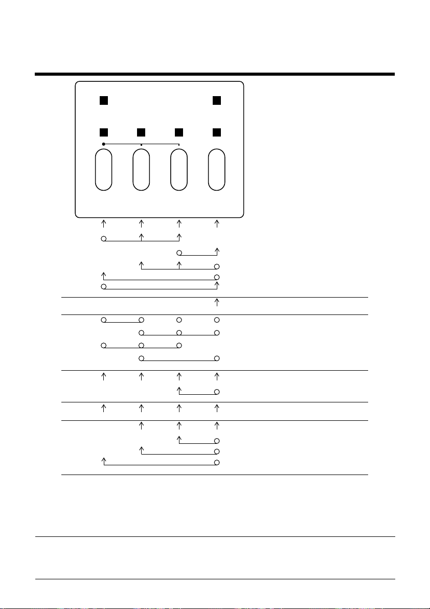
Appendix G: Control Panel Operation Guide
75
DATA
DRAFT
MULTI-
PART
Multi-part Eject Line feed
BANK SW ON/OFF Exit
EJECT LF ON LINE
Draft/LQ
Auto loading position change mode
Buffer clear & All reset
Hex dump Self test 2
EDS-2 mode
Left Right Next Exit
Back ward Forward Cancel
Factory setting
POWER
OCR B
OCR B
Form feed
Forward Micro feedBack ward
EDS-1 mode
Dot- adjustment mode
Print
Set
Save
On line
Off line
Self test 1
Off line
On line
Power on
EDS mode
Dot adjustment mode
Auto loading position change mode
Note:
A dot means press and hold and an arr ow means to just press. A dot and arr ow
tied together means hold one while pressing the other.
Page 82

A
auto LF with CR
auto load position
changing
AUTOEXEC.BAT
23
17
47, 49
B
bidirectional printing
C
carton contents
character pitch
setting
Character Set
IBM #1
IBM #2
IBM Special
international
Italic #2
character sets
tables
character table
character tables
Code Page
Arabic
Brazil-ABICOMP
Brazil-ABNT
Bulgarian
Canadian French
CS2
Estonian1
Estonian2
Gost-Russian
Greek
Hebrew
Hungarian
IBM-Russian
2
24
54
54
55
53
53
53
22
29
26
59
58
62
57
61
61
57
59, 60
62
57
56
23
58
56
Icelandic
Latin-2
Latvian1
Latvian2
Lithuanian #772
Lithuanian #774
Lithuanian-KBL
Maltese
Microwiz KU
Multi-lingual
Newsic TIS
Nordic
Polish
Popular TIS
Portuguese
Rajvitee KU
Russian
Standard KU
STD988 TIS
Turkish
connecting
to your computer
control panel
printer
cut-sheet paper
automatically feeding
ejecting
specifications
55
58
61
62
62
56
57
56
58
15
37
D
dot alignment
42
60
61
60
63
55
64
64
55
63
63
63
11
37
35
Page 83

4
E
EDS Mode
changing a switch setting
21
19
19
settings
19
21
20
21
default settings
definition
entering
21
exiting
printing current switch
selecting a bank
selecting a switch
settings
using
eject
Electronic DIP Switches
emulation
21, 22, 31
19
16
22
F
font
selecting
form feed
front cover
opening
16
16
G
glossary
graphics direction
75
23
H
hexadecimal dump 42
19
I
initialization 18
input buffer 22
Interface Converter
interface pin outs
L
line feed 16
line spacing 23
M
micro feed 16
MS-DOS
Multi-part Mode
O
off-line
ON-LINE
on-line
options
connecting 40
parallel interface 52
serial interface 52
setting up for printing 34
entering 18
switching to 15
indicator 15
switching to 15
serial interface unit 39
serial-to-parallel converter
40
Page 84

P
paper
handling 35
micro feed 16
recommended print area 38
selecting 35
paper eject 16
paper out detector 22
pass book
print area 38
printing 36
specifications 35
print mode 24
print pitch 24
printer buffer
clearing 17
problems
causes and solutions 44
dark printing 46
erratic operation 48
excessive noise 46
hot printer case 46
left margin movement 47
line spacing 45
malformed graphics 45
no printing 44
overprinting lines 45
paper feed 45
power supply 44
print quality 45
printing past paper edge 47
smudged forms 46
sudden stoppage 48
weak printing 44
wrong number of lines 45
R
RAM usage 22
ribbon cartridge
installing 6
removing 8
taking up slack in 7
S
setup
printer 1
specifications 50
system software settings
MS-DOS 48
T
test print 41
troubleshooting
guide 41
U
unidirectional printing 23
unpacking 2
Z
zero style 23
Page 85

Page 86

STAR MICRONICS ASIA LTD.
Rm 1802-6, 18/F., Tower 2, Enterprise Square
9 Sheung Yuet Road, Kowloon Bay Hong Kong
Tel: 852-2796-2727, Fax: 852-2799-9344
 Loading...