

Page 1
USER’S MANUAL
LC-500
DOT MATRIX PRINTER
CFA10EC 80826160
Page 2

Manufacturer’s Declaration of Conformity
CE
EC Council Directive 89/336/EEC of 3 May 1989
This product, has been designed and manufactured in accordance with the International
Standards EN 50081-1/01.92 and EN 50082-1/01.92, following the provisions of the Electro
Magnetic Compatibility Directive of the European Communities as of May 1989.
EC Council Directive 73/23/EEC and 93/68/EEC of 22 July 1993
This product, has been designed and manufactured in accordance with the International
Standards EN 60950, following the provisions of the Low Voltage Directive of the European
Communities as of July 1993.
The above statement applies only to printers marketed in EU.
Trademark acknowledgments
LC-500: Star Micronics Co., Ltd.
ESC/POS: Seiko Epson Corporation
Notice
• All rights reserved. Reproduction of any part of this manual in any form whatsoever, without
STAR’s express permission is forbidden.
• The contents of this manual are subject to change without notice.
• All efforts have been made to ensure the accuracy of the contents of this manual at the time
of going to press. However, should any errors be detected, STAR would greatly appreciate
being informed of them.
• The above notwithstanding, STAR can assume no responsibility for any errors in this manual.
©
Copyright 2003 Star Micronics Co., LTD.
Page 3

Contents
1. Printer Setup .............................................. 1
Choosing a place for the printer ....................................................... 1
Unpacking the printer ....................................................................... 2
Printer Components .......................................................................... 3
Installing the paper guide ................................................................. 4
Opening the printer cover ................................................................. 4
Removing the printer cover .............................................................. 5
Connecting the Power Cord and turning the power ON and OFF.... 6
Installing the ribbon cassette ............................................................ 7
Removing the ribbon cassette ......................................................... 10
Connecting to your computer using the parallel cable ................... 10
Ferrite Core Installation ................................................................... 11
2. Paper Handling ........................................ 13
Selecting paper types ...................................................................... 13
Cut-sheet paper ............................................................................... 13
Fanfold paper .................................................................................. 13
ENGLISH
Loading cut-sheet paper.................................................................. 14
Printing on cut-sheet paper ............................................................. 17
Loading fanfold paper .................................................................... 18
Printing on fanfold paper ................................................................ 22
Parking fanfold paper ..................................................................... 23
Unparking fanfold paper................................................................. 23
3. Control Panel Operations ....................... 24
Switching between on-line and off-line.......................................... 25
Page 4

Control panel functions in on-line mode ........................................ 25
Control panel functions in off-line mode ....................................... 27
4. Using the EDS Mode................................ 30
About EDS Mode settings .............................................................. 30
Entering the EDS Mode.................................................................. 30
Selecting a EDS number ................................................................. 31
Selecting a bank .............................................................................. 31
Selecting a switch ........................................................................... 31
Changing a switch setting ............................................................... 31
Printing the current EDS settings ................................................... 31
Exiting the EDS Modes .................................................................. 31
5. Control Codes List................................... 42
< ESC/P-K mode> .......................................................................... 42
6. Troubleshooting ....................................... 45
Short test ......................................................................................... 45
Long test ......................................................................................... 46
Hexadecimal dump ......................................................................... 46
Adjusting the dot alignment ........................................................... 47
Troubleshooting guide .................................................................... 48
Appendix A. Specifications ............................... 53
Appendix B. Character Sets ............................. 56
Appendix C. Control Panel Operation Guide.... 67
Page 5

1. Printer Setup
This chapter contains important information on setting up your printer. Be sure
to read this chapter carefully before using the printer for the first time.
Choosing a place for the printer
Before unpacking the printer from the box, plan the installation location
of your printer. Consider the following points.
✓ Choose a firm, level surface where the printer will not be exposed to
vibr ation.
✓ The power outlet you plan to connect to for power should be nearby
and unobstructed.
✓ Make sure that the printer is close enough to your computer for you
to connect the two with your printer cable.
✓ Allow six inches (15 centimeters) of free space on either side and in
the back of the printer.
✓ Make sure that the printer is not exposed to direct sunlight.
✓ Make sure that the printer is well away from heaters.
✓ Make sure that the surrounding area is clean, dry, and free of dust.
✓ Make sure that the printer is connected to a reliable power outlet. It
should not be on the same electric circuit as copiers, refrigerators, or
other appliances that cause power spikes.
✓ Use a power outlet that matches the power rating noted on the label
affixed to the bottom of your printer.
✓ Make sure that the room where you are using the printer is not too
humid.
– 1 –
Page 6
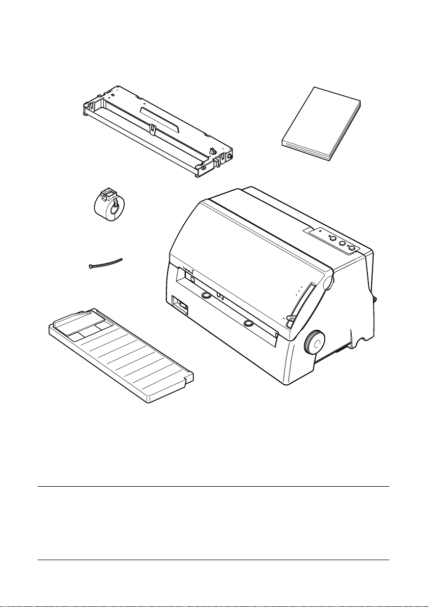
Unpacking the printer
Check that the package contains the following items.
ENGLISH
Ribbon cassette
Ferrite Core
Fastener
Printer
Paper guide
User,s manual
5
4
3
2
1
If any item is missing, contact the store where you bought the printer and
ask them to supply the missing part. Note that it is a good idea to keep the
original box and all packing materials in case you need to transport the
printer at a later date.
Important!
There are several versions of this printer designed for different
voltages. It is not possible to change the voltage of a printer. If the
voltage shown on the label on the back of your printer does not match
the voltage for your area, contact your dealer immediately.
– 2 –
Page 7
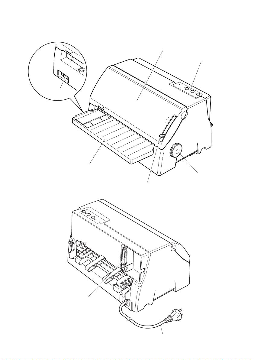
Printer Components
The following illustrations show the major components of your printer.
Power switch
Paper guide
Printer cover
5
4
3
2
1
Adjustment lever
Control panel
Platen knob
Parallel interface
connector
Power cord
– 3 –
Page 8
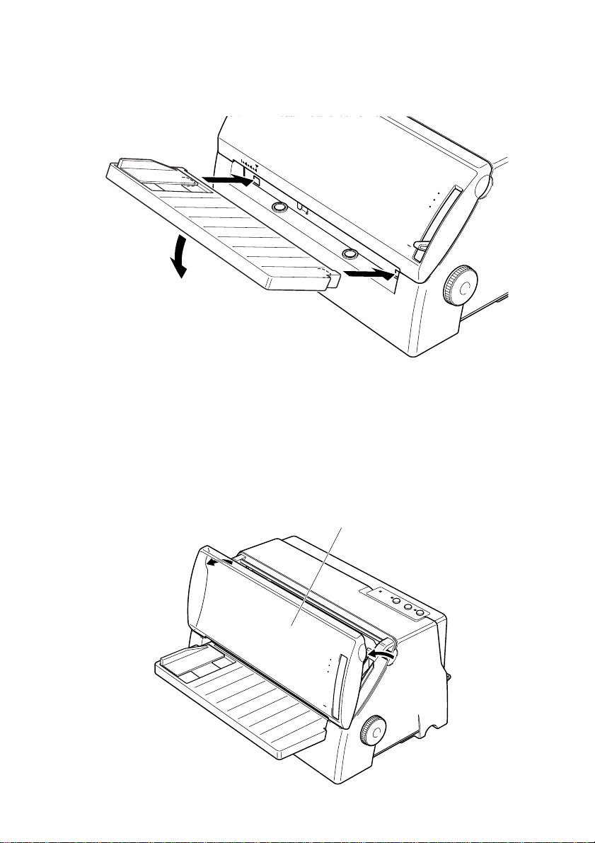
Installing the paper guide
4
5
1
2
3
1. Hold the paper guide at a slight angle and slide the two slots on either
side of the paper guide into the tabs provided on the printer case.
2. Press the paper guide firmly against the tabs until it clicks, and then
lower the table to a horizontal position.
Opening the printer cover
ENGLISH
Pull on the left and right corners of the printer cover to and swing it down
until it is fully open.
Printer cover
5
4
– 4 –
3
2
1
Page 9
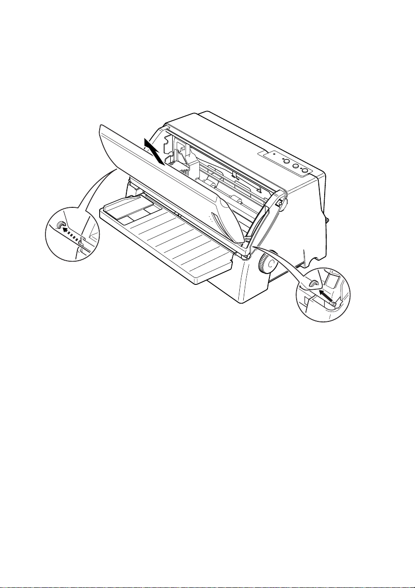
Removing the printer cover
4
5
1
2
3
Swing the printer cover so that it is at an angle as shown in the figure
below and lift the cover to remove it. To replace the printer cover, lower
the two slots on either side of the cover onto the tabs provided on the
printer case.
– 5 –
Page 10
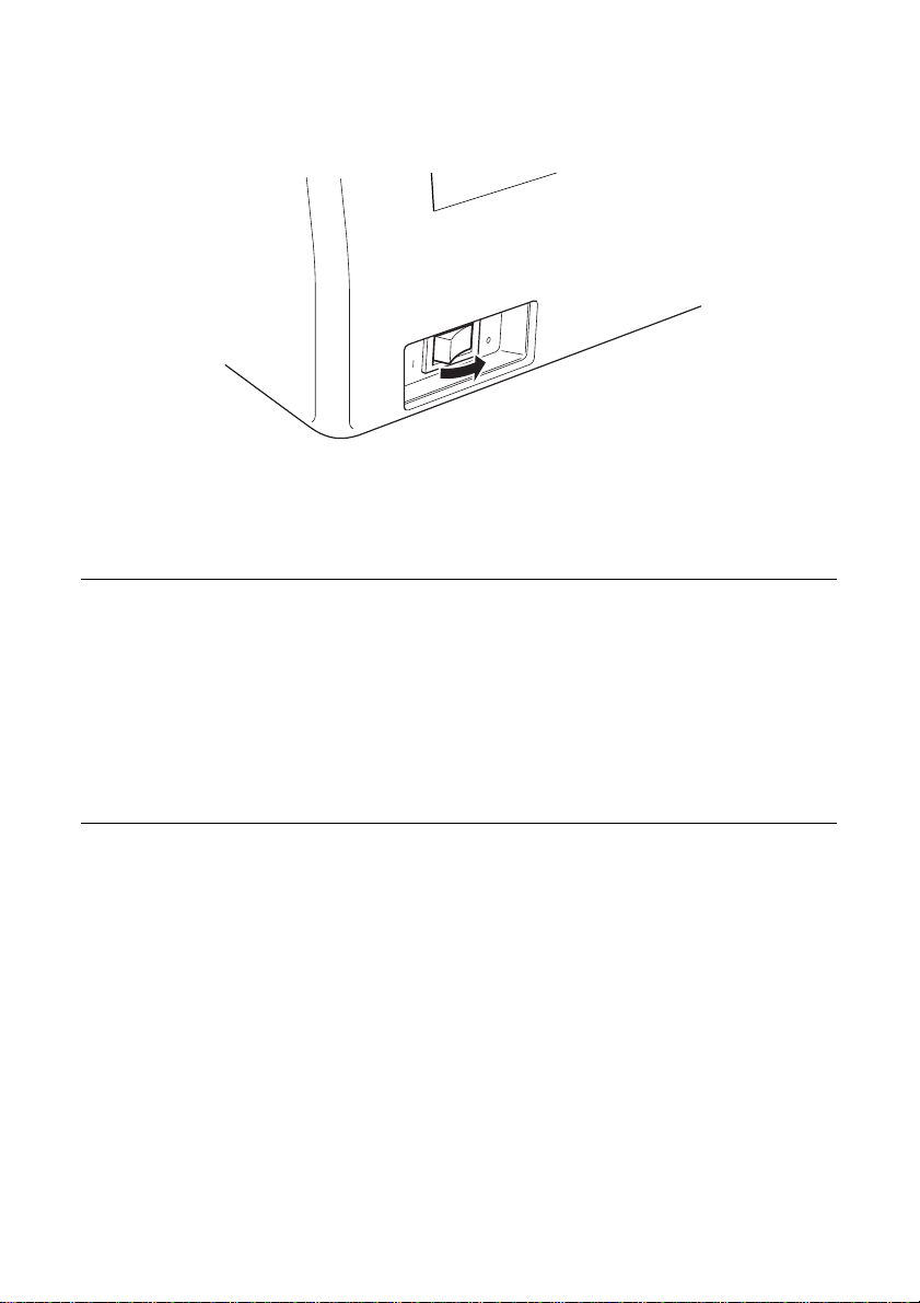
Connecting the Power Cord and turning the power ON and OFF
1. Check that the power switch on the front panel of the printer is in the
OFF position (O).
OFF
ON
2. Plug the power cord to a power outlet whose voltage matches the
power rating noted on the label affixed to the bottom of your printer.
Caution!
1. If the voltage marked on the rear of your printer does not match
the voltage from the outlet you are using, do not plug in the power
cord. Contact your dealer for assistance.
2. We recommend that you unplug the printer from the power outlet
whenever you do not plan to use it for long periods. Because of
this, you should locate the printer so that the power outlet it is
plugged into is nearby and easy to access.
ENGLISH
3. To turn the power on, press the power switch to the ON position (|);
to turn the power off, press the power switch to the OFF position (O).
– 6 –
Page 11
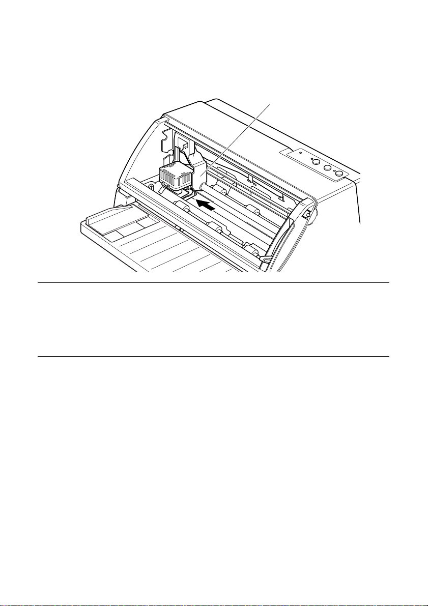
Installing the ribbon cassette
1. Turn the power on. The carriage moves to the left most position. You
will hear beeps when the carriage reaches this position.
Caution!
Do not move the carriage by hand while the printer is turned on.
Doing so can damage the printer.
If you have just finished printing, let the print head cool for a few
minutes before you touch it.
Carriage
2. Turn the power off.
– 7 –
Page 12
3. Set the adjustment lever to the highest position.
Adjustment lever
5
4
3
2
1
4. Open the printer cover.
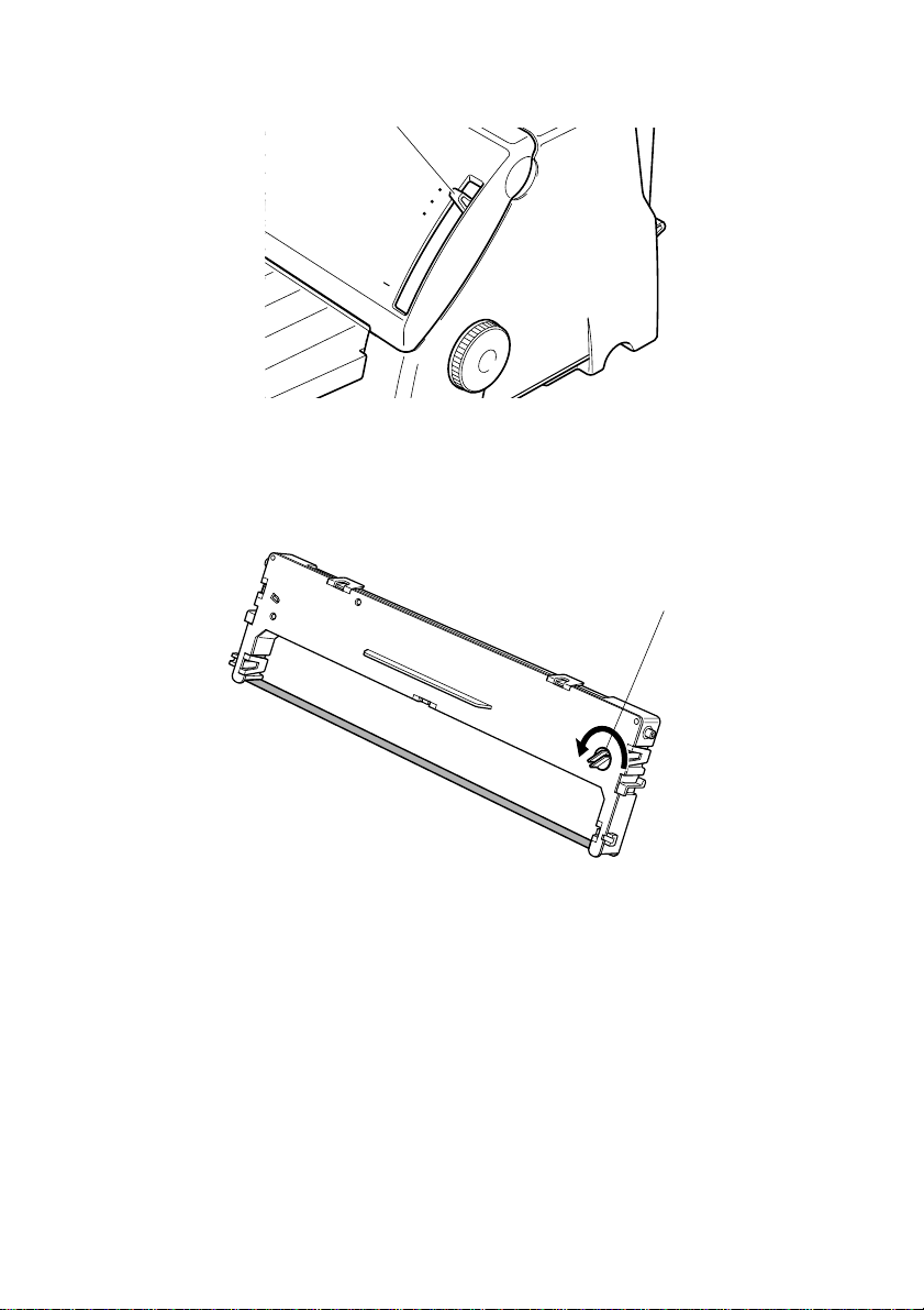
5. Remove the ribbon cassette from the package and rotate the knob on
the cassette counterclockwise to take up any slack in the ribbon.
Knob
ENGLISH
– 8 –
Page 13
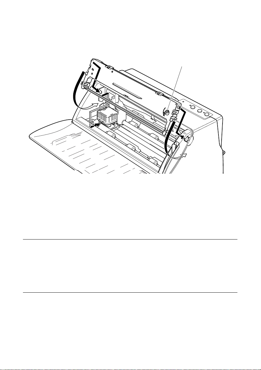
6. While holding the printer cassette at an angle, insert the two round
tabs on either side of the ribbon cassette into the two slots inside the
printer. Then, press the lower half of the cassette inward to a vertical
position until it snaps securely into place.
Knob
7. Rotate the knob on the cassette counterclockwise so that the ribbon
slides under the head.
8. Set the adjustment lever to position 1. Position 1 is for thin paper. You
may need to set the adjustment lever to another position, if you are
using a thick paper.
9. Close the printer cover.
Important!
Printing that is poor quality or too light is almost always due to a
ribbon that is simply worn out or “used up.” If you experience
problems with print quality, check the condition of the ribbon. If the
black part looks gray and well-worn, replace the ribbon with a new
one.
– 9 –
Page 14

Removing the ribbon cassette
When replacing the ribbon cassette, use the following procedure to
remove the old ribbon cassette from the printer.
1. Open the printer cover.
2. Turn the power on. The carriage moves to the left most position. You
will hear beeps when the carriage reaches this position.
Caution!
Do not move the carriage by hand while the printer is turned on.
Doing so can damage the printer.
If you have just finished printing, let the print head cool for a few
minutes before you touch it.
3. Turn the power off.
4. Pull the lower half of the cassette outward so that the ribbon slides out
from under the printer head. Then, lift up the cassette to remove it
from the printer.
Connecting to your computer using the parallel cable
ENGLISH
You printer comes equipped with a parallel port.
Since the printer does not come with cables, you must purchase an
appropriate cable that matches your computer. Below is an illustration of
a typical parallel cable.
Important!
The following instructions apply to the Centronics parallel cable that
is suitable for use with an IBM-compatible personal computer. Note
that they do not apply to all types of computers and cables. If you are
unsure about what type of cable you should use, consult your dealer.
For an IBM-compatible personal computer:
• Use a standard 36-pin Centronics parallel cable.
• The parallel cable should be no longer than six feet (two meters).
Longer cables can result in poor transfer of information.
– 10 –
Page 15
Ferrite Core Installation
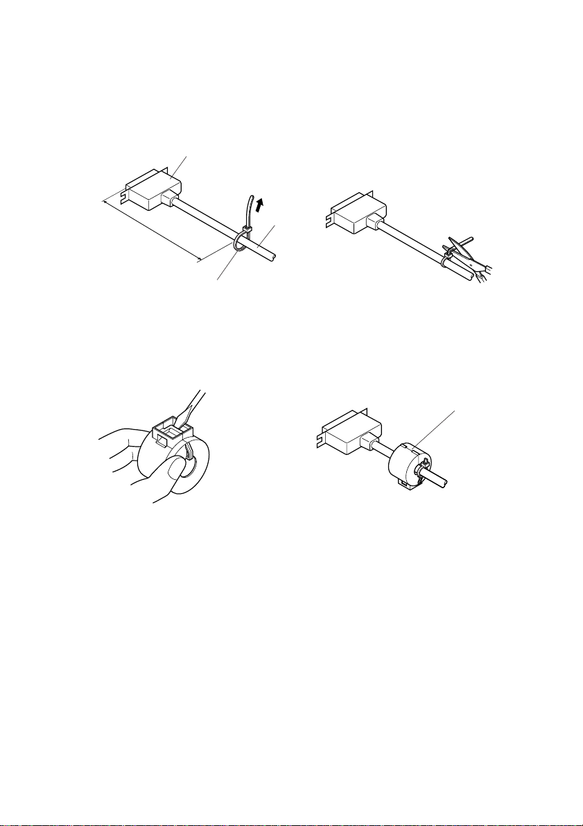
1. Strap the fastener into the parallel interface cable as shown in the
illustration below.
2. Cut off the surplus part of the fastener.
Ferrite Core
12 to 15 cm
Fastener
3. With a regular screwdriver, unlatch and open the ferrite core.
4. Attach the ferrite core onto the cable as shown in the illustration
below.
Cable
Ferrite Core
– 11 –
Page 16
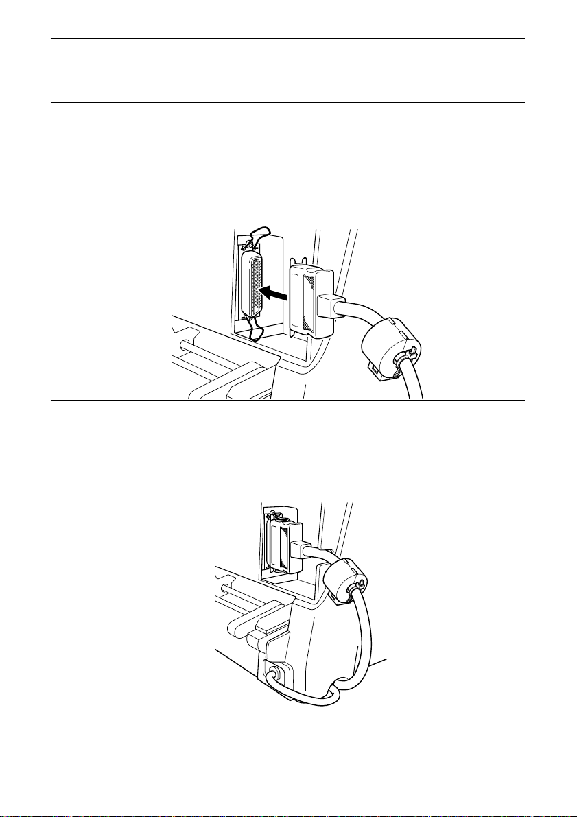
Important!
Make sure that the printer is unplugged from the AC outlet and that
the computer is turned off before connecting the parallel cable.
Note:
1. Connect one end of the parallel cable to the parallel port of your
computer. The parallel port is usually labeled “Printer,” “Parallel,”
“PRN,” “LPT1,” or something similar.
2. Connect the other end of the parallel cable into the socket on the back
of the printer and secure it in place with the clips.
If your computer is located to the right of the printer, run the cable
under the computer through the groove at the bottom of the printer.
This will prevent the cable from interfering with the fanfold paper.
You can also run the power cord under the printer.
ENGLISH
– 12 –
Page 17

This chapter describes the different types of paper you can print on and
how to setup the printer for each type.
Selecting paper types
Use the following information when selecting paper.
Cut-sheet paper
Width: 125 to 257 mm / 4.9 to 10.12 inches
Length: 85 to 364 mm / 3.3 to 14.33 inches
Paper Sizes: A6: 105 x 148 mm (Landscape)
Thickness
1-ply only: 0.05 to 0.18 mm
Multi-ply: 0.05 to 0.35 mm
Weight
1-ply only: 52 to 156 g/m
Multi-ply: 40 to 52 g/m
2. Paper Handling
B6: 128.5 x 182 mm (Portrait, Landscape)
A5: 148 x 210 mm (Portrait, Landscape)
B5: 182 x 257 mm (Portrait, Landscape)
A4: 210 x 297mm (Portrait)
B4: 257 x 364mm (Portrait))
Executive: 7.25 x 10.5 inches (Portrait)
Letter: 8.5 x 11 inches (Portrait)
Legal: 8.5 x 14 inches (Portrait)
2
/ 14 to 42 lbs / 45 to 135kg
2
/ 11 to 14 lbs / 34 to 45kg
Fanfold paper
Width: 139.7 to 254 mm / 5.5 to 10 inches
Length: Min. 5.5 inches
Thickness
1-ply only: 0.07 to 0.11 mm
Multi-ply: Max. 0.35 mm
Weight
1-ply only: 52 to 82 g/m
Multi-ply: 40 to 52 g/m
– 13 –
2
/ 14 to 22 lbs / 45 to 70kg
2
/ 11 to 14 lbs / 34 to 45kg
Page 18
Loading cut-sheet paper
This section describes the procedure for loading cut-sheet paper. You can
also use fanfold paper. For details on using fanfold paper, see “Loading
fanfold paper” on page 18. If the fanfold paper is currently loaded, first
park the fanfold paper using the procedures described in “Parking
fanfold paper” on page 23.
1. Set the release lever to the cut-sheet position.
2. Set the adjustment lever to the value that matches the thickness of the
paper you are using. The setting for normal paper is 1. Set the lever to a
larger value for thicker paper, or to a smaller value for thinner paper.
ENGLISH
5
4
3
2
1
Adjustment lever
4
3
2
1
– 14 –
5
Page 19
The following table provides a general guide for setting the adjustment
lever. Experiment with different settings until you find the one that gives
you the print quality you want.
Important!
Continuous use of the wrong adjustment lever setting can drastically
reduce the print head life. Position “–” is used only when the print
quality is too light. Setting the lever to position “–” when you are
using thin paper may damage the print head.
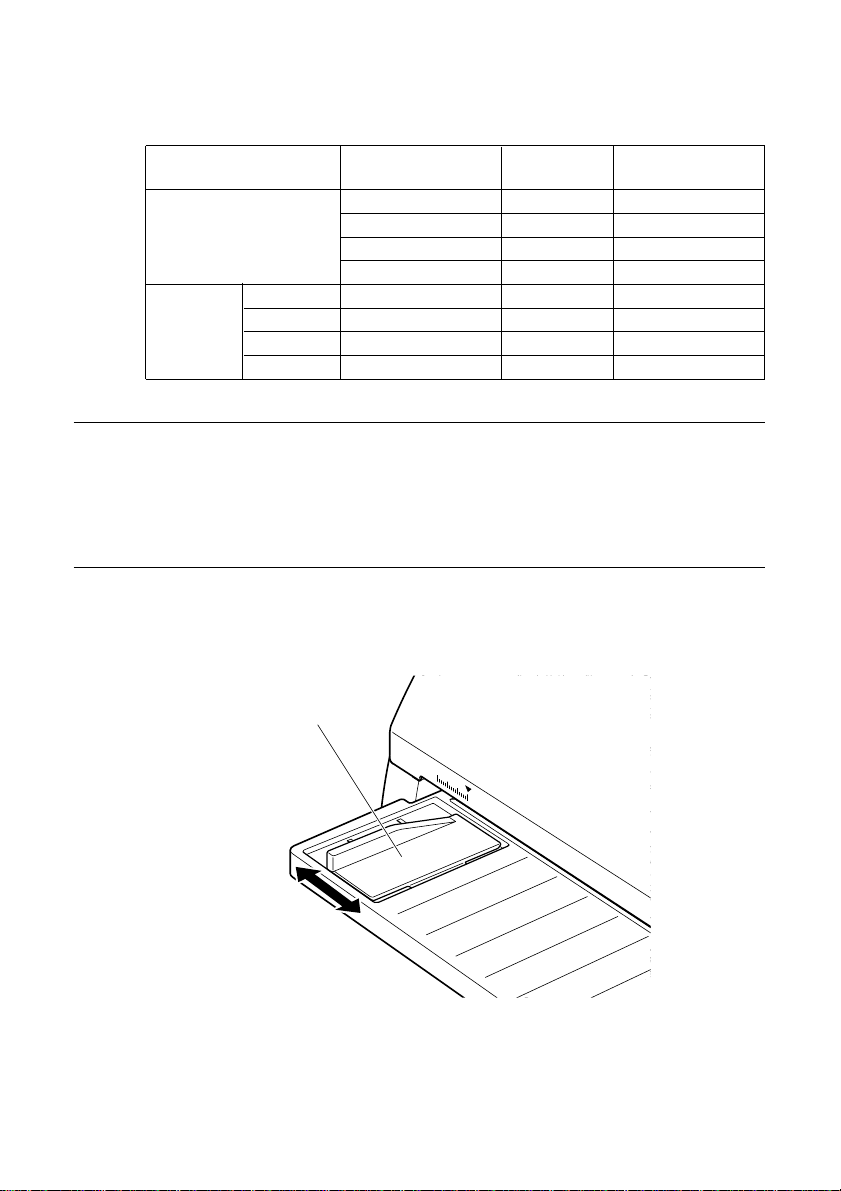
3. Adjust the paper edge to the desired position. The ▼ mark of the guide
Paper Type Weight Per Sheet Thickness
64 g/m
90 g/m
156 g/m
2
2
2
2
2
2
2
2
0.05 mm 1
0.08 mm 1
0.12 mm 1 to 2
0.19 mm 2
0.13 mm 2
0.20 mm 3
0.26 mm 5
0.32 mm 6
Single-sheet 30 g/m
Multi-part 2-ply 40 to 52 g/m
3-ply 40 to 52 g/m
4-ply 40 to 52 g/m
5-ply 40 to 52 g/m
indicates where the left margin of the printing will be.
Paper edge
Recommended
Position
– 15 –
Page 20
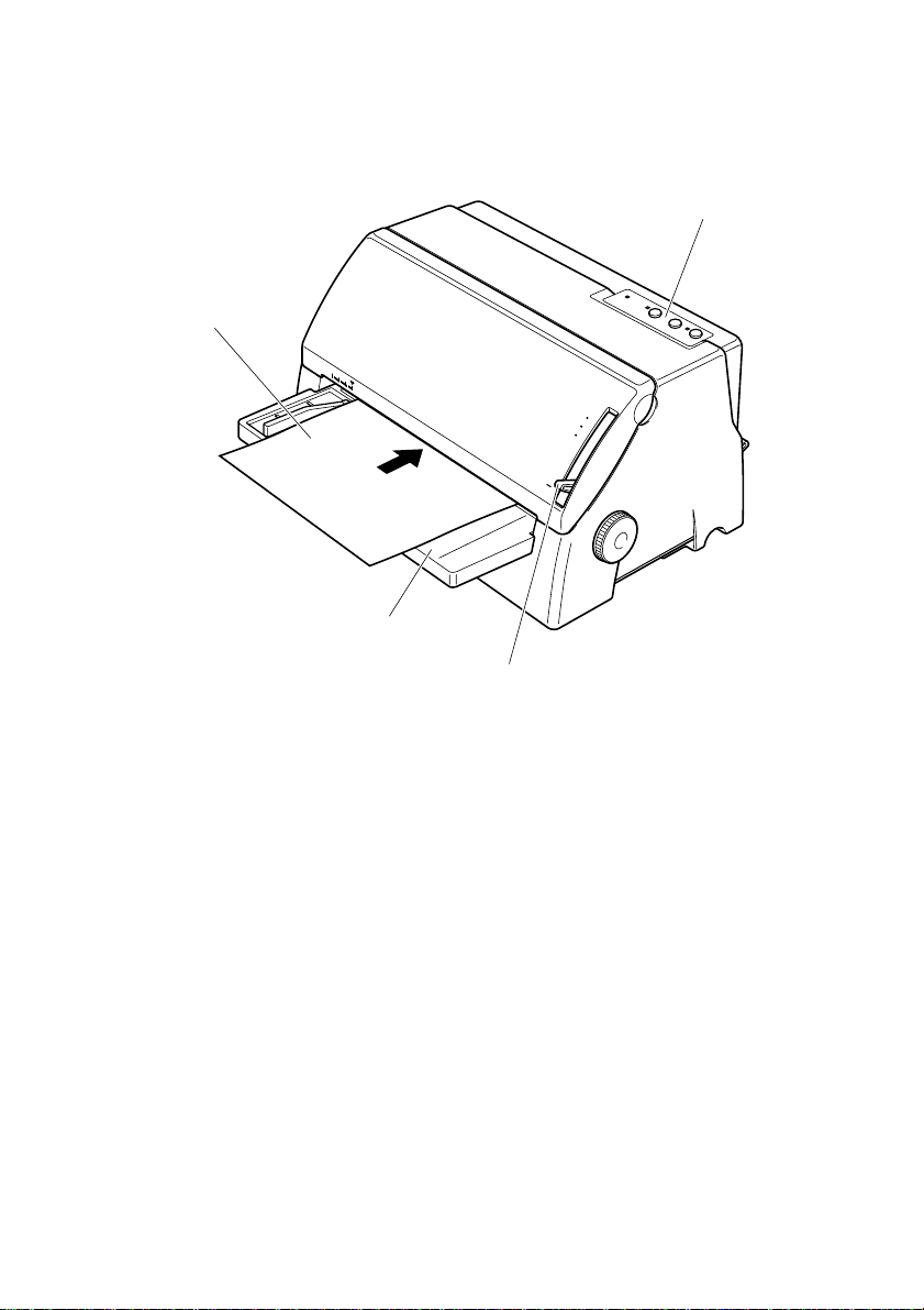
4. Insert the paper from the front of the printer as far as it will go, sliding
the left side of the paper against the paper edge. Insert the paper facing
up, with the top towards the printer.
Control panel
Paper
5
4
3
2
1
Peper guide
Adjustment lever
ENGLISH
The paper will automatically be fed into the printer.
5. Start the printing operation from your software application.
After the printing is complete, the paper is ejected from the same position
as you inserted the paper.
– 16 –
Page 21
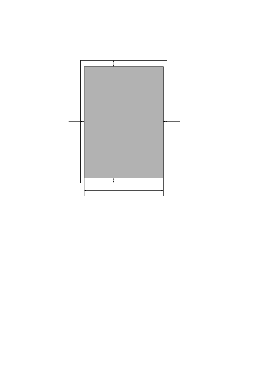
Printing on cut-sheet paper
The following shows the recommended print area for cut-sheet paper.
Cut-sheet paper
4.23 mm
3 mm
3 mm
6.35 mm
Max. 203.2 mm
(Max. 8 inches)
– 17 –
Page 22
Loading fanfold paper
This section describes the procedure for loading fanfold paper. You can
also use cut-sheet paper. For details on using cut-sheet paper, see
“Loading cut-sheet paper” on page 14.
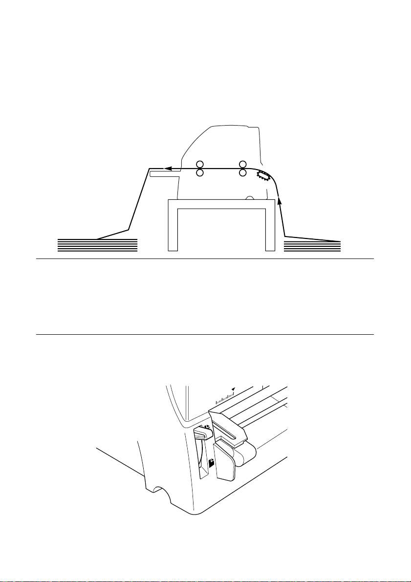
1. Position the stack of paper behind the printer. The following figure
Important!
To protect against paper jams, make sure that the fanfold paper is
stacked in a position that is lower than the printer.
To decrease paper jams, be sure that the perforations do not get
caught in anything in the paper path.
2. Make sure that the printer is turned off.
3. Set the release lever to the fanfold position.
ENGLISH
shows the correct path for fanfold paper.
– 18 –
Page 23

4. Set the adjustment lever to the value that matches the thickness of the
paper you are using. The setting for normal paper is 1. Set the lever
to a larger value for thicker paper, or to a smaller value for thinner
paper. See the table on page 15 for details.
5
4
3
2
1
Adjustment lever
5
4
3
2
1
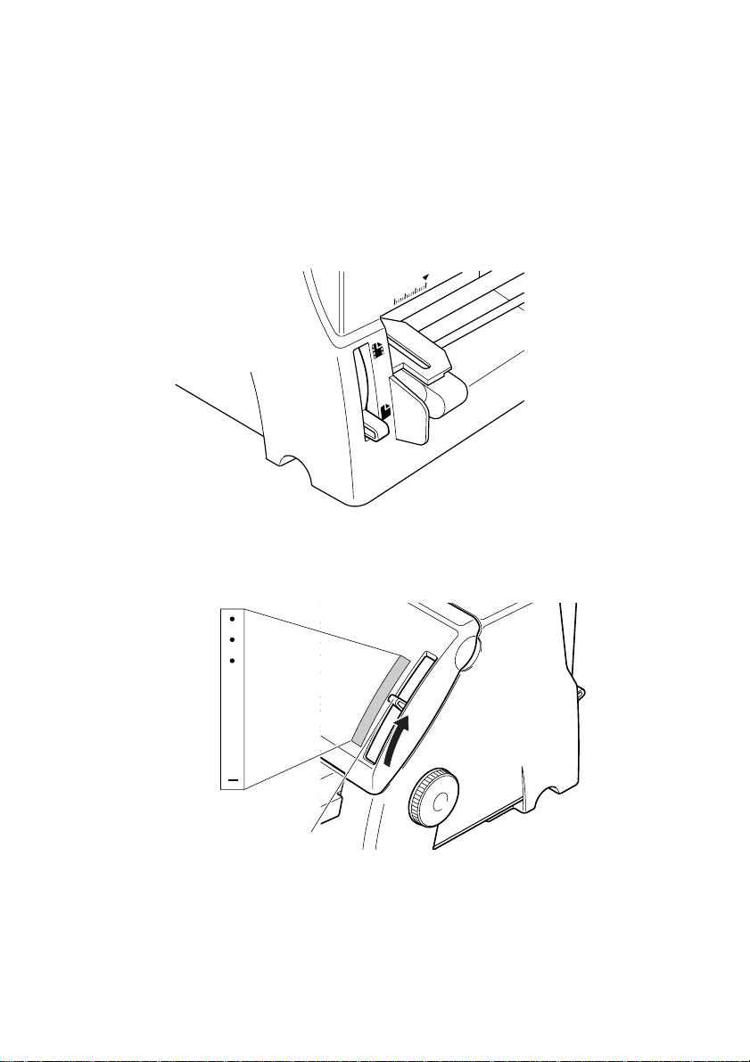
5. Unlock the tractor on the left (when viewing the printer from behind)
by pulling its gray lever up, and adjust the position of the left tractor.
Note that there is a guide inside the printer in front of the left tractor.
The ▲ mark of the guide indicates where the left margin of the
printing will be.
6. Once the left tractor is aligned the way you want it, push the gray lever
back down to lock it in place.
– 19 –
Page 24
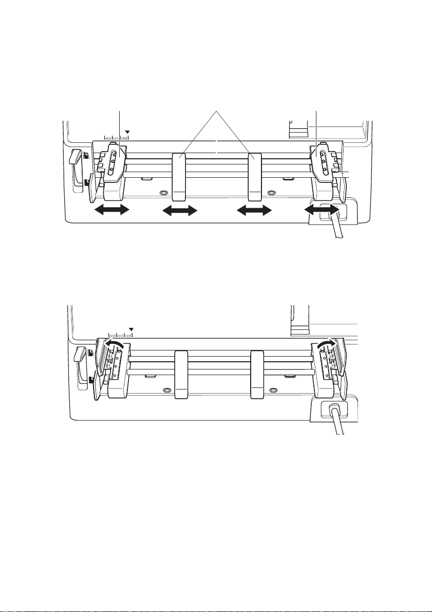
7. Now move the tractor on the right to the approximate position of the
right side of the paper you are using. Pull its gray lever up to unlock
it, and push the lever back down to lock it into place. Also move the
sheet guide so that it is approximately halfway between the two
tractors.
Sheet guidesPin tractor Pin tractor
8. Open the covers of both tractors and align the paper so that at least
three pins on the tractors are inserted into the holes of the paper.
ENGLISH
– 20 –
Page 25
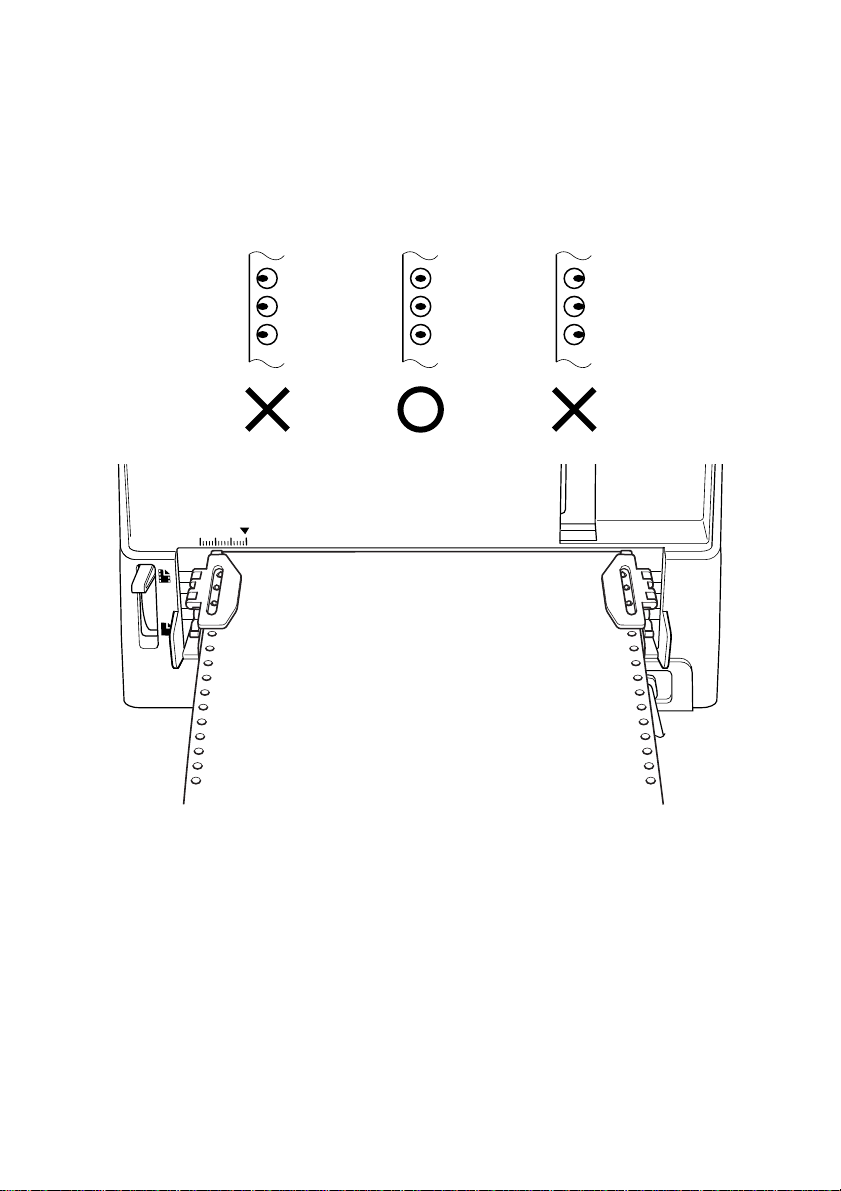
9. Close the tractor covers. At this point you can make final adjustments
to the paper position by releasing the gray levers and moving the
tractors. The paper should lie flat with no buckling or bulging (tractors
too close) or no stretching or elongation of the holes (tractors too far
apart). After making these adjustments, be sure that you re-lock the
tractors by pushing the gray levers back into their original positions.
10.Turn the power on.
11.Press the control panel’s SET/PARK/EJECT button and the paper
will feed to the starting position.
– 21 –
Page 26

Printing on fanfold paper
When printing on fanfold paper, take care not to print too close to the
perforations that separate each sheet. The following shows the
recommended print area for fanfold paper and cut-sheet paper.
4.23 mm
First page
3 mm
ENGLISH
Cut-sheet paperFanfold paper
4.23 mm
3 mm
Perforation
18 mm
Perforation
Bottom of
Form
4.23 mm
4.23 mm
4.23 mm
4.23 mm
142 mm
18 mm
Last page
6.35 mm
Max. 203.2 mm
(Max. 8 inches)
– 22 –
Page 27

Parking fanfold paper
It is not necessary to remove fanfold paper currently loaded in the printer
in order to print on cut-sheet paper. Instead, simply use the following
procedure to park the fanfold paper.
1. Press the control panel’s ON LINE button to put the printer off-line.
2. Press the control panel’s SET/PARK/EJECT button. The printer
automatically reverse feeds the fanfold paper until it is no longer in
contact with the platen, which is indicated by the printer beeping a
number of times. Also, the control panel’s POWER indicator starts to
flash because paper is not loaded.
You can now load cut-sheet paper into the printer using the procedures
described in “Loading cut-sheet paper” on page 14.
Unparking fanfold paper
After you are finished printing on cut-sheet paper, use the following
procedure to unpark fanfold paper and make it available for printing.
1. Remove all cut-sheet paper from the printer.
2. Set the release lever to the fanfold position.
3. Press the SET/PARK/EJECT button to feed the paper to the starting
position.
The printer automatically goes back on-line at this time.
– 23 –
Page 28

3. Control Panel Operations
The control panel gives you push-button control over the printer’s
operations. It also includes indicator lights, which tell you the current
status of the printer at a glance.
SET/PARK/EJECT button
LINE FEED button
ON LINE button
ENGLISH
POWER
P.E.
POWER indicator
MODE
SET/PARK
EJECT
MICRO FEED
PRINT MODE indicator
TEAR OFF
LINE FEED
ON LINE
FORM FEED
ON LINE indicator
This chapter describes control panel functions that can be performed
while the printer is turned on and either on-line or off-line. The buttons
perform different functions in the EDS and Dot Adjustment Modes.
Functions of control panel buttons in these modes are described in the
relevant sections covering them.
– 24 –
Page 29

Switching between on-line and off-line
• Press the ON LINE button to switch the printer between on-line and
off-line modes.
• When the printer is on-line, the ON LINE indicator is lit and the
printer can receive data from the computer. Make sure that the printer
is on-line whenever you are trying to print.
• When the printer is off-line, the ON LINE indicator is off, which
means that the printer cannot receive any data.
• Note that you can also press the ON LINE button while a printing
operation is in progress to stop the printing.
Control panel functions in on-line mode
Tear-off function (fanfold paper)
This procedure feeds fanfold paper to a position where it can be torn off
easily.
1. Press the LINE FEED button to feed the paper automatically so that
the perforation is just past the printer cover.
2. Tear the paper along the perforation.
When you resume printing, the printer reverse feeds the paper to its
former position.
Print mode selection
Press the SET/PARK/EJECT button to change the print mode selection.
When the print mode is changed, a short buzzer sounds. The mode
indicator tells you the current print mode as follows:
Print Mode Mode Indicator
LQ (Letter Quality) OFF
Draft ON
– 25 –
Page 30

Panel lock mode
When the printer is in the panel lock mode, the mode settings you make
on the control panel are used even if your software tries to override the
mode. Use the following procedure to enter the panel lock mode.
1. While holding down the SET/PARK/EJECT button, press the LINE
FEED button. A short buzzer sounds once.
To exit from the panel lock mode, press the LINE FEED button while
holding down the SET/PARK/EJECT button. A short buzzer sounds
twice.
Panel macro
The settings you make on the front panel are cleared when the printer is
turned OFF. To save the current control panel settings so that they are
used the next time the printer is turned ON, use the following procedure.
1. While holding down the SET/PARK/EJECT button, press the ON
LINE button. Keep both buttons held down until the printer beeps
twice.
This procedure saves the following settings.
To clear the panel macro, hold down SET/PARK/EJECT and ON LINE
until the printer beeps 3 times. If EDS2A-5 is OFF, this panel macro
function is ignored (see chapter 4).
ENGLISH
Print mode settings
Panel lock
– 26 –
Page 31

Control panel functions in off-line mode
Line feed
Press the LINE FEED button once to feed the paper one line. Holding
down the LINE FEED button continually feeds the paper, 1/6” (default)
at a time, until you release the button.
The line feed is executed using the current line feed value. In Self Test
mode, this button is ignored. While this button is held down, line feed is
executed up to 13 times. If the button is held down after 13 times of line
feed, the paper is continuously fed to the top of the next page. If the ON
LINE button is pressed while this button is held down, form feed is
executed.
Set/Park/Eject
Press the SET/PARK/EJECT button to set, eject, or park the paper.
If the paper is not loaded (paper end condition), paper loading is
executed. After the paper is loaded completely, the printer switches online mode. If the paper is loaded (not paper end condition), the paper is
parked when using fanfold paper or ejected when using cut-sheet paper.
After the paper is parked or ejected completely, the printer switches to
off-line mode.
Paper End Not Paper End
When using fanfold paper Paper load (Paper set) Paper park
When using cut-sheet paper Paper load (Paper set) Paper eject
Paper Condition
Form feed
While holding down the LINE FEED button, press the ON LINE button
to feed the paper to the top of the next page. If EDS2C-2 is ON (default)
when using cut-sheet paper, this function executes paper ejection.
– 27 –
Page 32

Micro paper feed
Use the following procedure to feed the paper in 1/60-inch increments. This
function can be used to align the print head exactly where you want it.
Press the LINE FEED button while holding down the ON LINE button
to execute micro paper feed. When Tear Off lifts the paper up, the micro
paper feed value is added to the tear off value. If the adjust value is over
1 inch, the micro paper feed is not executed.
Press the SET/PARK/EJECT button while holding down the ON LINE
button to execute micro reverse paper feed. When Tear Off lifts the paper
up, the micro reverse paper feed value is subtracted from the tear off
value. If the adjust value is over 1 inch, the micro reverse paper feed is
not executed.
Auto loading position change mode
While holding down the LINE FEED button, press the SET/PARK/
EJECT button. The printer enters the auto loading position change mode.
When the auto loading position change mode is entered, a short buzzer
sounds twice, and all LEDS turn ON. If paper is loaded (not paper end
condition), the paper is ejected when using cut-sheet paper or parked
when using fanfold paper. If the paper is not parked or ejected completely,
the printer exits from the auto loading position change mode, sounds a
short buzzer three times, and sets the LEDs back to the previous
condition. Below are the button assignments in auto loading position
change mode.
ENGLISH
Pressing the ON LINE button
If paper end condition, the printer executes paper loading.
If not paper end condition, the printer exits from the auto loading
position change mode and ignores the change.
Holding down the ON LINE button and pressing the LINE FEED button
The printer exits from the auto loading position change mode, and the
auto loading values are reset to factory default.
Holding down the ON LINE button and pressing the SET/PARK/EJECT
button
The printer exits from the auto loading position change mode, and the
change is effective until the next change (setting is kept in EEPROM).
– 28 –
Page 33

Pressing the LINE FEED button
The printer executes micro forward paper feed, and the auto loading
value is increased.
Pressing the SET/PARK/EJECT button
The printer executes micro reverse paper feed, and the auto loading
value is decreased.
The auto loading value must be greater than 0 inch. If the auto loading
value is less than 14/360 inch, the micro reverse paper feed is not
executed.
A micro paper feed moves the paper by 1/60 inch. When the printer exits
from the auto loading position change mode, a short buzzer sounds twice,
and all LEDs return to their previous conditions.
Set top of form (TOF)
While holding down the SET/PARK/EJECT button, press the LINE
FEED button. The vertical position is reset to the first line.
Buffer clear & All reset
While holding down the SET/PARK/EJECT button, press the ON LINE
button. Keep both buttons held down until the printer beeps once to clear
the data buffer. Continue to hold down both buttons until the printer
beeps again three times to reset all the settings.
After releasing the buttons, the printer is initialized in the same way as
a power-on reset.
– 29 –
Page 34
4. Using the EDS Mode
EDS stand for Electronic DIP Switches. Just like the small DIP switches
that are used by computers, printers, and other devices, the EDS lets you
configure the printer for your application.
This chapter describes how to enter the printer’s EDS Mode and provides
details about available settings and how to change them.
About EDS Mode settings
The EDS Mode of this printer actually consists of five sub-modes, named
EDS-1 to EDS-5. EDS settings are grouped among four “banks”
(representing banks of switches) that are identified by the letters A
through D. Each bank contains a number of “switches” numbered 1
through 7 that you can turn on and off to configure the printer.
Entering the EDS Mode
1. Make sure that paper is loaded in the printer.
2. Turn off the printer.
3. To enter the EDS Mode, turn the printer on while holding down the
control panel’s LINE FEED, and ON LINE buttons.
ENGLISH
This causes the following message to be printed, which indicates the
printer is in the EDS Mode.
– 30 –
Page 35

Selecting a EDS number
In the EDS Modes , use the control panel’s LINE FEED button, while
holding down SET/PARK/EJECT button to select a EDS number.
When pressed the button, current setting of the bank is printed.
Selecting a bank
While in the EDS Modes , use the control panel’s SET/PARK/EJECT
button to select a bank. When pressed the button, current setting of the
bank is printed.
Selecting a switch
While in the EDS Modes , use the control panel’s LINE FEED button
to select a switch. When pressed the button, current setting of the is
switch printed.
Changing a switch setting
After selecting a bank and a switch, press the control panel’s ON LINE
button to turn the switch on and off. When pressed the button, changed
setting of the switch is printed.
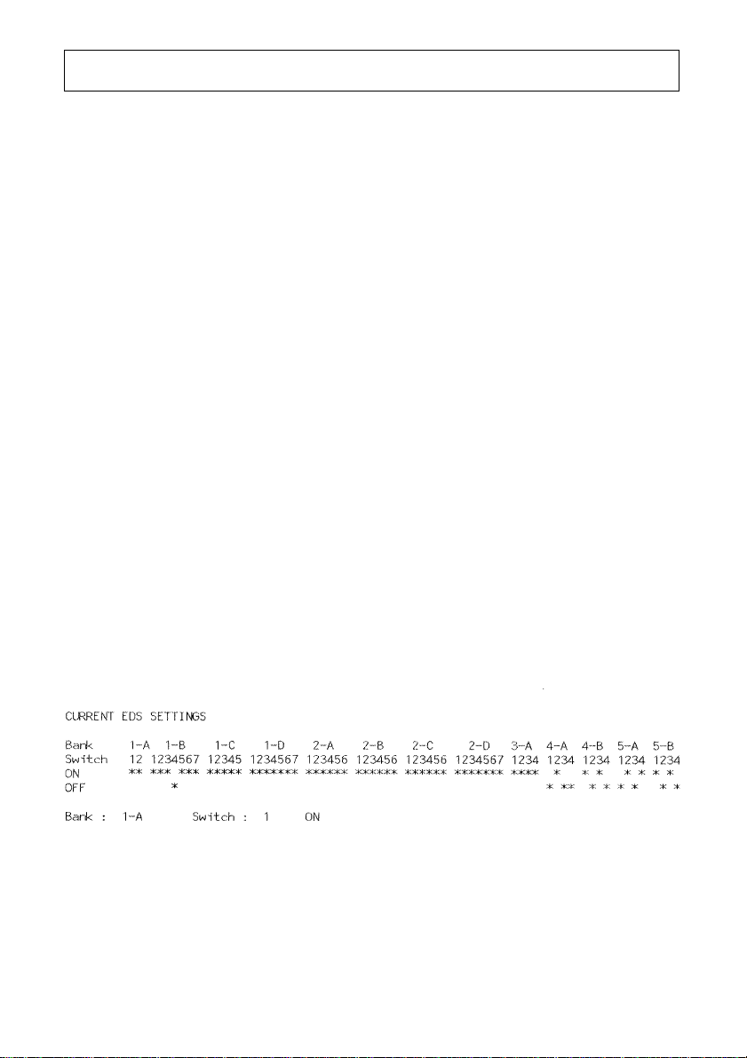
Printing the current EDS settings
While holding down LINE FEED button, press the control panel’s ON
LINE button to print out the current switch settings. Asterisks on the
printout show whether a switch is turned on or off.
Exiting the EDS Modes
While holding down SET/PARK/EJECT button, press the control
panel’s ON LINE button to exit the EDS Modes.
– 31 –
Page 36
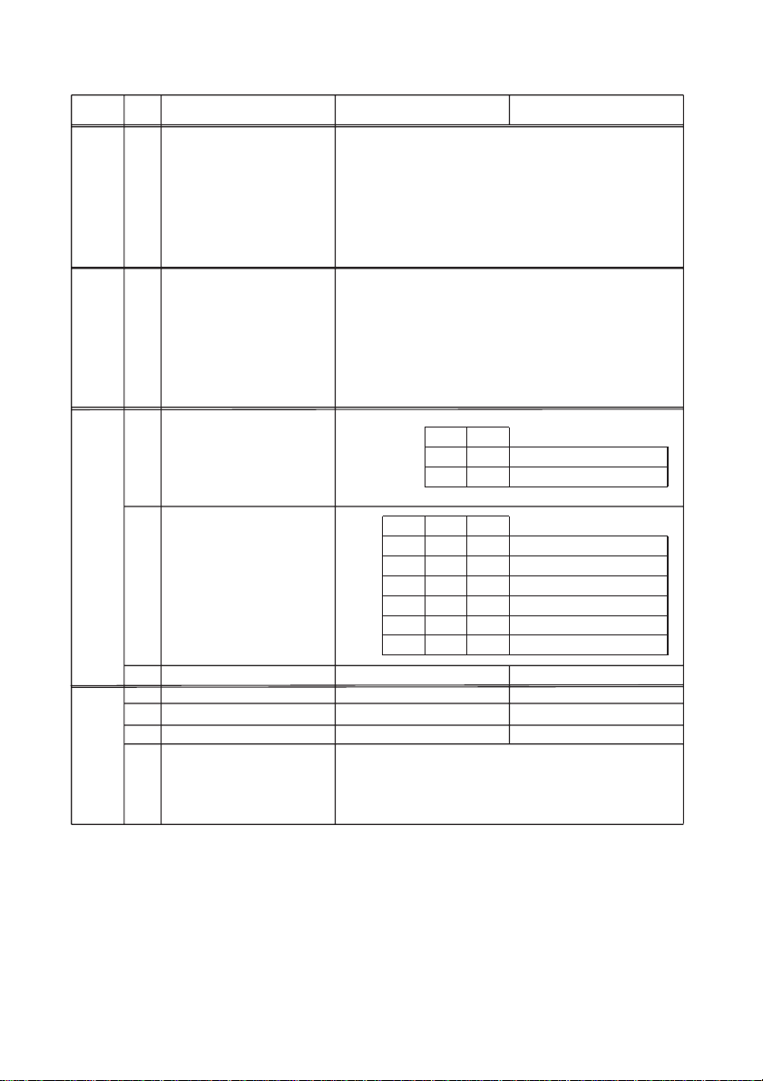
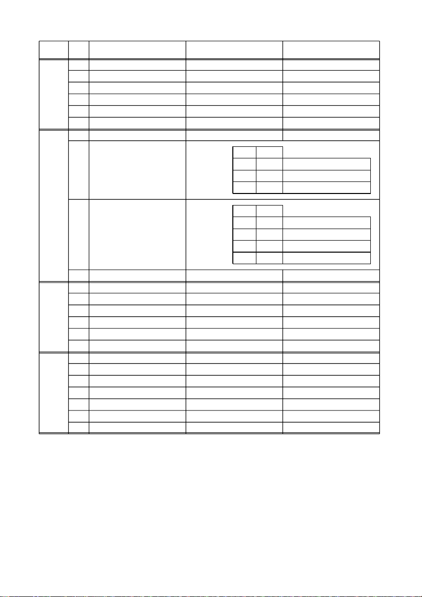
Use the information in the following table to change the EDS settings.
< EDS-1>
BANK
SW OFFONFUNCTION
( Reserved )
1
A
2
3
4
5
6
7
B
C
D
( Reserved )
1
2
3
4
5
6
7
Print mode
1
2
Character pitch
3
4
5
LQ Font
6
Character table
1
Character set
2
Zero style
3
4
( Reserved )
5
6
7
1 2
ON ON LQ (x1) *
OFF ON Draft (x3)
3 4 5
ON ON ON 10 CPI *
ON ON OFF 12 CPI
ON OFF ON 15 CPI
ON OFF OFF 17 CPI
OFF ON ON 20 CPI
OFF ON OFF Proportional
Roman*
IBM Graphics *
#2 *
Normal *
Sanserif
Italic
#1
Slashed zero
*: Default setting
ENGLISH
– 32 –
Page 37

Printer mode
The relation between the printer quality and the printer speed is as
follows:
Printer quality LQ > Draft
Printer speed Draft > LQ
The values inside the parentheses are print speed ratios with
respect to LQ.
Character table / IBM character set
See Appendix B, “Character set” for details.
– 33 –
Page 38
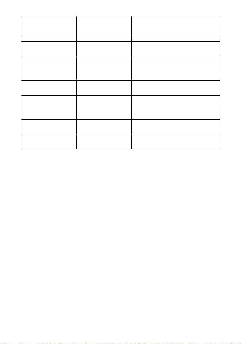
< EDS-2>
BANK
SW OFFONFUNCTION
A
B
C
D
Input buffer
1
Auto CR with LF
2
Auto LF with CR
3
Buzzer
4
Saving Control Panel Status
5
Quiet mode
6
Auto Tear-off
1
Multi-part mode
2
3
Waiting period for
4
Paper loading
5
75% Compress mode
6
Line spacing
1
FF command
2
Eject direction
3
Eject paper at Power ON
4
Skip over perforation
5
Paper out detector
6
Print direction
1
Print direction command
2
CR centering at top of form
3
CR wiping at top/bottom
4
2-pass printing at top/bottom
5
Strobe timing
6
ACK timing
7
Large ( 54.5 K bytes ) *
Enabled *
Disabled *
Enabled *
Panel Macro *
Disabled *
Disabled *
23
ON ON Auto selection *
ON OFF Multi-part mode
OFF ON Normal mode
45
ON ON 0.5 sec.
ON OFF 1.0 sec.
OFF ON 1.5 sec.
OFF OFF 2.0 sec.
Disabled *
1/6" *
Eject *
Front *
Enabled *
Disabled *
Enabled *
Bi-directional *
Disabled *
Disabled *
Disabled *
Disabled *
Normal *
Normal *
Small ( 1K byte )
Disabled
Enabled
Disabled
Auto Saving
Enabled
Enabled
Enabled
1/8"
Form Feed
Rear
Disabled
Enabled
Disabled
Uni-directional
Enabled
Enabled
Enabled
Enabled
Special
Special
*: Default setting
ENGLISH
– 34 –
Page 39

Auto CR with LF
When auto CR (carriage return) with LF (line feed) is enabled, the printer
automatically performs a carriage return whenever it receives a LF code
from the computer. This moves the print position to the beginning of the
next line. If the printer adds an extra line after every carriage return, select
OFF.
Auto LF with CR
When auto LF with CR is enabled (OFF), the printer automatically
performs a line feed whenever it receives a CR code from the computer.
When disabled (ON), the computer must send both a line feed code and
a carriage return code at the end of each line. Most computers and
applications send both.
Note the following check points when determining which setting to use.
• If you find that your output is double-spaced when it should not be,
turn this switch ON (disabled).
• If you find that lines are printing over each other, turn this switch OFF
(enabled).
Saving Control Panel Status
You can select either “Panel Macro” or “Auto Saving” to save the current
control panel settings. See “Panel macro” on page 26.
Quiet mode
When the Quiet Mode is enabled (OFF), the printer prints with less noise
than normal printing. Though the Quiet Mode prints more quietly, it also
takes considerably longer than normal printing.
Auto Tear-off
Specifies whether the printer’s auto tear-off feature is enabled (OFF) or
disabled (ON). Note that this setting controls the application software’s
tear-off function only. It does not affect the manual tear-off function that
is performed using the control panel buttons as described on page 25. The
manual tear-off function is always enabled.
– 35 –
Page 40

Multi-part mode
When the printer is in the Multi-part Mode, the print head prints with
greater impact. It should be noted, however, that printing in the Multipart Mode also reduces the life of the print head. Because of this, you
should use the Multi-part Mode only for printing on four or five-ply
paper. Use the Normal Mode for printing on one to three-ply paper. When
Auto (SW2: ON, SW3: ON) is selected, the printer automatically
switches between the Multi-part Mode and Normal Mode according to
the adjustment lever position. The Normal Mode is automatically selected when the adjustment lever is at any setting of 3 or less, while the
Multi-paper mode is selected for settings greater than 3.
Waiting period for Paper loading
This function sets the amount of wait time between paper insertion and
paper feeding. If the paper feeds before you can adjust the paper position
to your satisfaction, increase the wait time.
75% Compress mode
In the compression mode, the printer is able to receive print data for up
to 10.6-inch printing width. The print data is compressed from 10.6
inches to 8 inches (compression ratio of 75%).
ENGLISH
FF command / Eject direction
These functions are valid when the release lever is set to the cut-sheet
paper position.
Eject paper at Power ON
This function is valid when the release lever is set to the cut-sheet paper
position. This function selects whether to eject the cut-sheet paper when
a cut-sheet paper is on the paper guide at power on.
Skip over perforation
This function is valid only when fanfold paper is selected. When enabled,
the printer provides a one-inch margin between the last line printed on
one page and the first line printed on the next page.
– 36 –
Page 41

Print direction
This function selects bi-directional printing or uni-directional printing.
Printing is normally bi-directional, but uni-directional printing allows
for precise vertical printing alignment.
Print direction command
When disabled (ON), the preset printing direction overrides the print
direction commands sent by your software.
CR centering at top of form
This function is used to improve the paper feed precision when inserting
paper, ejecting paper, printing at the top or bottom edge of a paper, and
printing near the perforation of a fanfold paper. CR centering refers to the
operation of moving the carriage near the center of the paper. When
enabled (OFF), the printer performs CR centering at the positions
indicated above.
CR wiping at top/bottom
When enabled (OFF), the carriage moves to prevent a paper jam when the
printer inserts or ejects a curled paper.
2-pass printing at top/bottom
This function performs 2-pass printing when printing within 1/6 inch of
a perforation or 1/6 inch of the top or bottom edge of a paper. When
enabled (OFF), the printer performs 2-pass printing to prevent a paper
jam when printing at the positions indicated above.
Strobe timing
Selecting Normal (ON) allows the printer to receive data from the
computer when the parallel interface’s strobe signal falls. Selecting
Special (OFF) allows data receipt when the strobe signal rises.
ACK timing
Specifies the relation between the ACK (acknowledge) timing and the
BUSY timing. When set to Normal, the BUSY signal is activated while
ACK is being output. When set to Special, the BUSY signal is activated
after ACK is output.
– 37 –
Page 42

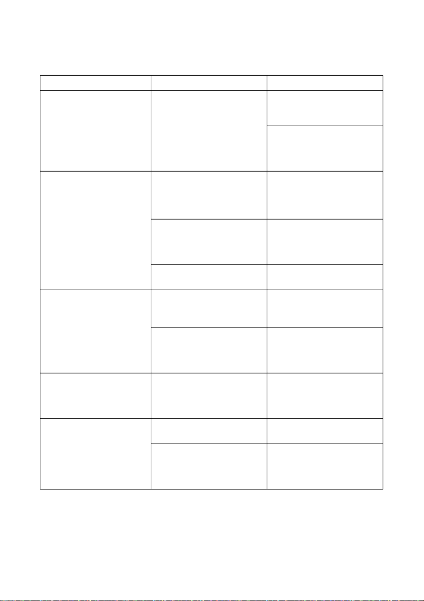
< EDS-3>
BANK
SW OFF ONFUNCTION
1
A
2
3
4
1
B
2
3
4
5
International character
set
Code Page
1 2 3 4 5
ON ON ON ON ON #437 U.S.A *
ON ON ON ON OFF #737 Greek
ON ON ON OFF ON #772 Lithuanian
ON ON ON OFF OFF #774 Lithuanian
ON ON OFF ON ON #850 Multi-lingual
ON ON OFF ON OFF #851 Greek
ON ON OFF OFF ON #852 Latin-2
ON ON OFF OFF OFF #858 Multi-lingual with Euro
ON OFF ON ON ON #860 Portuguese
ON OFF ON ON OFF #861 Icelandic
ON OFF ON OFF ON #863 Canada French
ON OFF ON OFF OFF #865 Nordic
ON OFF OFF ON ON #866 Russian
ON OFF OFF ON OFF #869 Greek
ON OFF OFF OFF ON #928 Greek
ON OFF OFF OFF OFF #1001 Arabic
OFF ON ON ON ON #2001 Lithuanian-KBL
OFF ON ON ON OFF #3001 Estonian-1
OFF ON ON OFF ON #3002 Estonian-2
OFF ON ON OFF OFF #3011 Latvian-1
OFF ON OFF ON ON #3012 Latvian-2
OFF ON OFF ON OFF #3021 Bulgarian
OFF ON OFF OFF ON #3031 Hebrew
OFF ON OFF OFF OFF #3041 Maltese
OFF OFF ON ON ON #3840 IBM-Russian
OFF OFF ON ON OFF #3841 Gost
OFF OFF ON OFF ON #3843 Polish
OFF OFF ON OFF OFF #3844 CS2
OFF OFF OFF ON ON #3845 Hungarian
OFF OFF OFF ON OFF #3846 Turkish
OFF OFF OFF OFF ON #3847 Brazil-ABNT
OFF OFF OFF OFF OFF #3848 Brazil-ABICOMP
1 2 3 4
ON ON ON ON U.S.A *
ON ON ON OFF France
ON ON OFF ON Germany
ON ON OFF OFF England
ON OFF ON ON Denmark-1
ON OFF ON OFF Sweden
ON OFF OFF ON Italy
ON OFF OFF OFF Spain-1
OFF ON ON ON Japan
OFF ON ON OFF Norway
OFF ON OFF ON Denmark-2
OFF ON OFF OFF Spain-2
OFF OFF ON ON Latin America
OFF OFF ON OFF Korea
OFF OFF OFF ON Ireland
OFF OFF OFF OFF Legal
ENGLISH
– 38 –
*: Default setting
Page 43

International character set
See Appendix C, “Character set” for details.
Code page
A code page is the set of symbols and characters that your printer can
print. Your printer converts ASCII hexadecimal data according to a code
page to print symbols and characters. By supporting different code
pages, the printer can print in a variety of different languages. The
following table shows detailed information about code pages.
Code Page Name Country Remarks
#437 U.S.A United Kingdom, France, Germany, Italy,
#737 Greek Greece Almost 80%
#772 Lithuanian Lithuania New standard
#774 Lithuanian Lithuania
#850 Multi-lingual United Kingdom, France, germany, Italy, Preferred by Microsoft
#851 Greek Greece
#852 Latin-2 Croatia, Czech Republic, Hungary, Preferred by Microsoft
#858 Multi-lingual with Euro
#860 Portuguese Portugal
#861 Icelandic Iceland
#863 Canada French Canada
#865 Nordic Denmark, Finland, Norway, Sweden Preferred by Microsoft
#866 Russian Russia Preferred by Microsoft
#869 Greek Greece
#928 Greek Greece for UNIX
#1001 Arabic Egypt, Saudi Arabia Mainly in Arabic speaking
#2001 Lithuanian-KBL Lithuania Commonly used for DOS
#3001 Estonian-1 Estonia
#3002 Estonian-2 Estonia Most often used
#3011 Latvian-1 Latvia
#3012 Latvian-2 Latvia Government standard
#3021 Bulgarian Bulgaria
#3031 Hebrew Israel
#3041 Maltese Malta
#3840 IBM-Russian Russia, Bulgaria
#3841 Gost Russia Gost: government standard
#3843 Polish Poland Also called “Mazovia”
#3844 CS2 Czech Republic Also called “Kamenicky”
#3845 Hungarian Hungary
#3846 Turkish Turkey
#3847 Brazil-ABNT
#3848 Brazil-ABICOMP
Austria, Switzerland, United States, Spain
Austria, Switzerland, United States, Spain
Poland, Romania, Serbia, Slovak
Republic, Slovenia
countries
– 39 –
Page 44

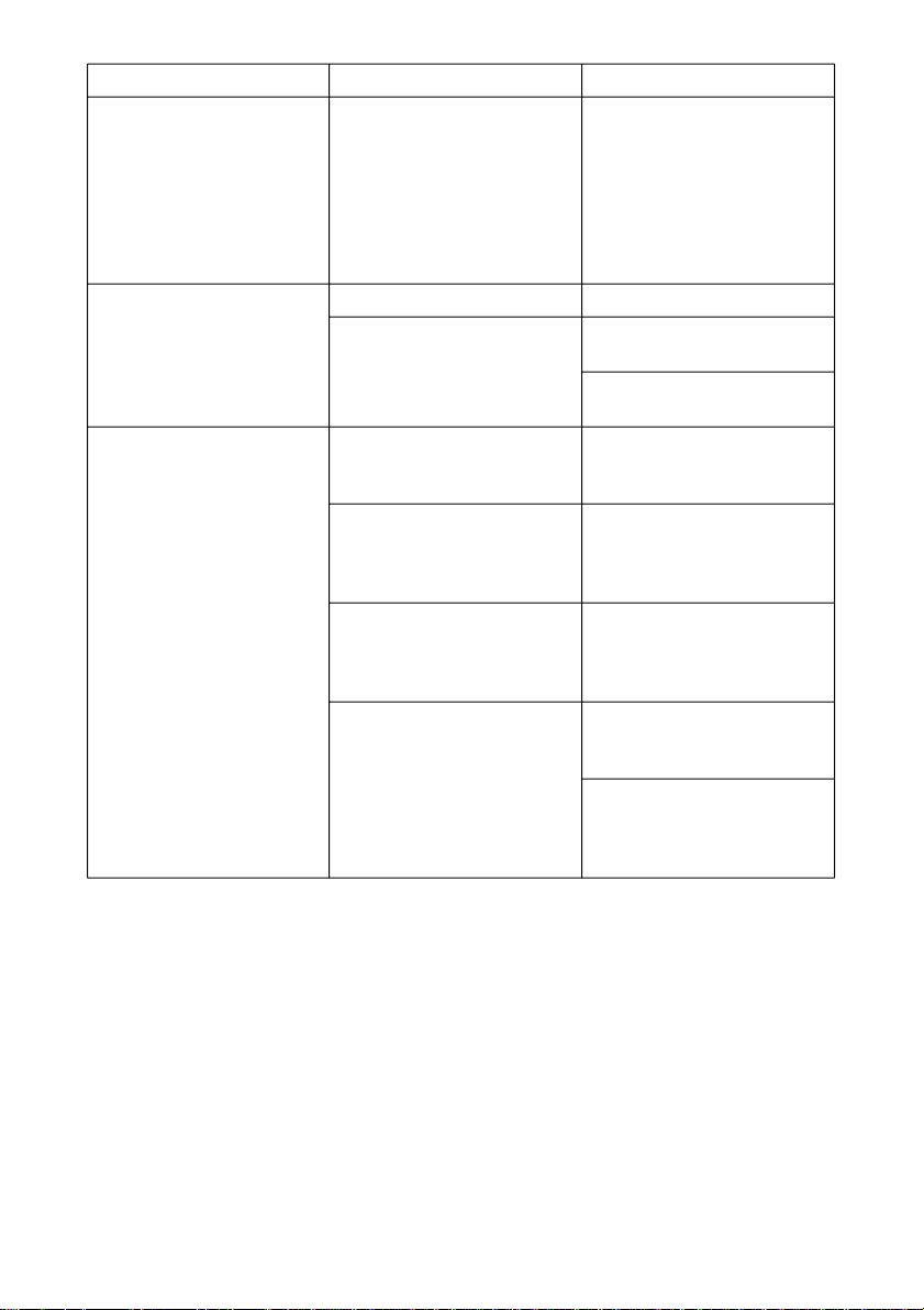
< EDS-4>
BANK SW OFFONFUNCTION
Page length
1
A
(Cut-sheet paper)
2
3
4
1 2 3 4
ON ON ON ON ON ON ON OFF ON ON OFF ON 3.5 inch
ON ON OFF OFF 11/3 inch
ON OFF ON ON 4.0 inch
ON OFF ON OFF 5.5 inch
ON OFF OFF ON 6.0 inch
ON OFF OFF OFF 7.0 inch
OFF ON ON ON 8.0 inch
OFF ON ON OFF 8.5 inch
OFF ON OFF ON 11.0 inch
OFF ON OFF OFF 11.7 inch / A4 *
OFF OFF ON ON 12.0 inch
OFF OFF ON OFF 14.0 inch
OFF OFF OFF ON (17.0 inch)
ENGLISH
B
Top margin
1
(Cut-sheet paper)
2
Bottom margin
3
(Cut-sheet paper)
4
Page length (Cut-sheet paper)
The print quality for the values enclosed in parentheses (17.0 inch) is not
guaranteed.
1 2
ON ON 1.0 mm (1-pin)
ON OFF 1/6 inch * (1-pin)
OFF ON 9.24 mm (1-pin)
OFF OFF 1 inch (24-pin)
3 4
ON ON 1.0 mm (24-pin)
ON OFF 1/6 inch * (24-pin)
OFF ON 1/2 inch (24-pin)
*: Default setting
– 40 –
Page 45

< EDS-5>
BANK SW OFFONFUNCTION
Page length
1
A
(Fanfold paper)
2
3
4
1 2 3 4
ON ON ON ON ( 11/4 inch )
ON ON ON OFF ( 3.0 inch )
ON ON OFF ON ( 3.5 inch )
ON ON OFF OFF ( 11/3 inch )
ON OFF ON ON ( 4.0 inch )
ON OFF ON OFF 5.5 inch
ON OFF OFF ON 6.0 inch
ON OFF OFF OFF 7.0 inch
OFF ON ON ON 8.0 inch
OFF ON ON OFF 8.5 inch
OFF ON OFF ON 11.0 inch *
OFF ON OFF OFF 11.7 inch / A4
OFF OFF ON ON 12.0 inch
OFF OFF ON OFF 14.0 inch
OFF OFF OFF ON 17.0 inch
B
Top margin
1
(Fanfold paper)
2
Bottom margin
3
(Fanfold paper)
4
Page length (Fanfold paper)
The print quality for the values enclosed in parentheses (11/4 inch to 4.0
inch) are not guaranteed.
1 2
ON ON 1.0 mm (1-pin)
ON OFF 1/6 inch * (1-pin)
OFF ON 9.24 mm (1-pin)
OFF OFF 1 inch (24-pin)
3 4
ON ON 1.0 mm (24-pin)
ON OFF 1/6 inch * (24-pin)
OFF ON 1/2 inch (24-pin)
OFF OFF 1 inch (24-pin)
*: Default setting
– 41 –
Page 46

5. Control Codes List
< ESC/P mode>
Command HEX code Function
BEL 07 Beeper
BS 08 Backspace
HT 09 Tab horizontally
LF 0A Line feed
VT 0B Tab vertically
FF 0C Form feed
CR 0D Carriage return
SO 0E Select Double-width printing (1 line)
SI 0F Select Condensed printing
DC2 12 Cancel Condensed printing
DC4 14 Cancel Double-width printing (1 line)
CAN 18 Cancel line
DEL 7F Delete last character in buffer
ESC SO 1B 0E Select Double-width printing (1 line)
ESC SI 1B 0F Select Condensed printing
ESC SP n 1B 20 n Set inter character space
ESC ! n 1B 21 n Master select
n = 00 n = 00 10 CPI (ESC P)
01 01 12 CPI (ESC M)
02 02 Proportional (ESC p)
04 04 Condensed (SI)
08 08 Emphasized (ESC E)
10 10 Double-strike (ESC G)
20 20 Double-wide expanded (ESC W)
40 40 Italic (ESC 4)
ESC # 1B 23 Cancel MSB control
ESC $ nL n
ESC % n 1B 25 n Turn User-defined character on / off
ESC & 0 n m [ a0 a1 a2 d ... 1B 26 30 n m [ a0 a1 a2 d ... Define User-defined characters
ESC ( - nL nH m d1 d
ESC ( B nL nH k m s v1 v21B 28 42 nL nH k m s v1 v2Select Bar-code printing
ESC * m nL nH d1...d
ESC + n 1B 2B n Set n/360" line spacing
ESC - n 1B 2D n Turn under lining mode on / off
ESC / n 1B 2F n Select vertical tab channel
ESC 0 1B 30 Select 1/8" line spacing
ESC 2 1B 32 Select 1/6" line spacing
ESC 3 n 1B 33 n Select n/180" line spacing
ESC 4 1B 34 Select italic font
ESC 5 1B 35 Cancel italic font
ESC 6 1B 36 Enable printing of upper control codes
ESC 7 1B 37 Enable upper control codes
ESC 8 1B 38 Disable paper out detector
ESC 9 1B 39 Enable paper out detector
80 80 Underlining (ESC -)
H
1B 24 nL n
H
Set absolute horizontal print position
n = 00 n = 00 Turns User-defined character off
01 01 Turns User-defined character on
2
k
n = 00 n = 00 Turns underline off
01 01 Turns underline on
1B 28 2D nL nH m d1 d
1B 2A m nL nH d1...d
k
Select or cancel score
2
Select Bit-image mode
(Character set #2)
(Character set #1)
– 42 –
ENGLISH
Page 47

ESC : 0 n 0 1B 3A 30 n 30 Copy standard character ROM font into
RAM
ESC < 1B 3C Select Unidirectional mode (1 line)
ESC = 1B 3D Set MSB to 0
ESC > 1B 3E Set MSB to 1
ESC ? n m 1B 3F n m Reassign Bit-image mode
ESC @ 1B 40 Initialize Printer
ESC A n 1B 41 n Set n/60" line spacing
ESC B d1...dk NUL 1B 42 d1...dk 00 Set vertical tab
ESC C n 1B 43 n Set page length in lines
ESC C NUL n 1B 43 00 n Set page length in inches
ESC D n1...nk NUL 1B 44 n1...nk 00 Set horizontal tab
ESC E 1B 45 Select Bold mode
ESC F 1B 46 Cancel Bold mode
ESC G 1B 47 Select Double-strike printing
ESC H 1B 48 Cancel Double-strike printing
ESC J n 1B 4A n Advance print position vertically (n/180")
ESC K nL nH d1...d
ESC L nL nH d1...d
ESC M 1B 4D Select 12 CPI (Elite)
k
k
1B 4B nL nH d1...d
1B 4C nL nH d1...d
k
k
Select Single-density Bit-image mode
Select Double-density Bit-image mode
ESC N n 1B 4E n Set Skip over perforation
ESC O 1B 4F Cancel Skip over perforation
ESC P 1B 50 Select 10 CPI (Pica)
ESC Q n 1B 51 n Set right margin
ESC R n 1B 52 n Select international character set
n = 00 n = 00 #0 U.S.A.
01 01 #1 France
02 02 #2 Germany
03 03 #3 England
04 04 #4 Denmark I
05 05 #5 Sweden
06 06 #6 Italy
07 07 #7 Spain I
08 08 #8 Japan
09 09 #9 Norway
0A 0A #10 Denmark II
0B 0B #11 Spain II
0C 0C #12 Latin America
0D 0D #13 Korea
0E 0E #14 Ireland
40 40 #64 Legal
ESC S n 1B 53 n Select Superscript / Subscript printing
n = 00 n = 00 Superscript
01 01 Subscript
ESC T 1B 54 Cancel Superscript / Subscript printing
ESC U n 1B 55 n Turn Unidirectional mode on / off
n = 00 n = 00 Bi-directional
ESC W n 1B 57 n Turn Double-width printing on / off
01 01 Unidirectional
n = 00 n = 00 Turns off double-width
01 01 Turns on double-width
ESC Y nL nH d1...d
ESC Z nL nH d1...d
ESC \ nL n
ESC b m n1...nk NUL 1B 62 m n1...nk 00 Set vertical tab in VFU channels
k
k
H
1B 59 nL nH d1...d
1B 5A nL nH d1...d
1B 5C nL n
H
k
k
Select High-speed Double-density Bitimage mode
Select Quadruple-density Bit-image mode
Move relative horizontal print position
ESC g 1B 67 Select 15 CPI
ESC j n 1B 6A n Advance reverse feed (n/180")
– 43 –
Page 48
ESC k n 1B 6B n Select Type style family
n = 00 n = 00 Roman
01 01 Sanserif
ESC l n 1B 6C n Set left margin
ESC p n 1B 70 n Turn proportional mode on / off
ESC q n 1B 71 n Select character style
ESC s n 1B 73 n Select quiet mode
ESC t n 1B 74 n Select character table
ESC w n 1B 77 n Turn Double-high printing mode on / off
ESC x n 1B 78 n Select print mode (ANK)
05 05 OCR B
n = 00 n = 00 Returns to current fixed character pitch
01 01 Selects proportional spacing
n = 00 n = 00 Cancel shadow / outline printing
01 01 Set outline printing
02 02 Set shadow printing
03 03 Set shadow & outline printing
n = 00 n = 00 Prints at normal speed
01 01 Prints at low speed
n = 00 n = 00 Select italic character table
01 01 Select Codepage character table
02 02 Select Download character table
03 03 Select Codepage character table
n = 00 n = 00 Turns off double-high
01 01 Turns on double-high
n = 00 n = 00 Draft
01 01 LQ
ENGLISH
– 44 –
Page 49

6. Troubleshooting
The appendix will provide help if you experience problems with your printer. It
tells you how to test the printer, how to check system software settings, and how
to adjust the vertical alignment. In addition, there is information on actions to take
for specific problems, and on the meanings of printer beep tones.
Warning!
The printer uses high voltage. Do not attempt any other repair or maintenance
except as expressly recommended in this appendix. Unauthorized repair
and maintenance not only exposes you to the danger of electrical shock, it
also may damage your printer and void your warranty.
Short test
Use the following procedure to test the printer to make sure that
everything is working correctly.
1. Make sure that paper is loaded in the printer.
2. Turn off the printer.
3. While holding down the control panel’s ON LINE button, turn the
printer back on.
4. The short self-test prints the following information.
1) The version number of the software contained in the printer’s ROM.
2) All EDS settings.
If there is no paper at power on, self-printing starts after the paper is
loaded by the panel. In self-printing, only paper end detection is
available. All panel functions are ignored. After self-printing finishes,
the printer will reset.
– 45 –
Page 50

Long test
Use the following procedure to test the printer to make sure that
everything is working correctly.
1. Make sure that paper is loaded in the printer.
2. Turn off the printer.
3. While holding down the control panel’s LINE FEED button, turn the
printer back on.
4. The short self-test prints the following information.
1) Rolling ASCII 7 lines.
2) All ASCII characters.
Draft 10 cpi, 12 cpi, and 15 cpi
ROMAN 10 cpi, 12 cpi, and 15 cpi
3) All Kanji characters.
Note:
Test printing prints across the entire width of the carriage. Make sure
that the printer is loaded with the widest paper available in order to avoid
damage to the print head and platen.
Hexadecimal dump
ENGLISH
This procedure prints in hexadecimal format all codes (character codes
and control codes) that are sent to the printer by the computer. The printer
does not execute any control codes (such as 0A - linefeed), it just prints
them out. The hexadecimal dump is useful when you are writing
programs for printer control.
1. Make sure that paper is loaded in the printer.
2. Turn off the printer.
3. While holding down the control panel’s SET/PARK/EJECT button,
turn the printer back on to enter the Hex Dump Mode.
4. To exit the Hex Dump Mode, turn the printer off.
– 46 –
Page 51

Adjusting the dot alignment
You may never have to use the procedure described in this section, but after you
have been using your printer for some time you may find that the dots of some
graphics do not align correctly. For example, what should look like:
may come out looking like one of the following:
This is caused when mechanical parts of the printer get out of alignment. This
happens only rarely and you may never experience it at all throughout the life of
the printer. If you do have problems, use the following procedure to correct it.
1. Make sure that paper is loaded in the printer.
2. Turn off the printer.
3. While holding down the control panel’s SET/PARK/EJECT and
LINE FEED buttons, turn the printer back on to enter the Dot
Adjustment Mode.
The printer will print something like the following.
or like this
Note that the printer will feed the paper forward and back each time
during this operation so you can view the printout.
4. If the two lines do not align properly, use SET/PARK/EJECT to move
the lower line to the left or LINE FEED to move it to the right.
The above step performs alignment for Normal-density mode only.
You must make separate adjustments for the CRT graphics, Doubledensity, Draft-Text, Triple-density, CRT graphics II, Quadrupledensity, LQ Text modes as well.
5. Press ON LINE to change to the next printing mode.
Press LINE FEED while holding down ON LINE to change to the
previous printing mode.
6. Repeat the above steps for each printing mode, if necessary.
7. After making changes to the adjustments, press SET/PARK/EJECT
while holding down ON LINE to exit the Dot Adjustment Mode and
register your adjustments.
– 47 –
Page 52
Troubleshooting guide
Use the following table to help track down the causes of problems and to
determine the best solution to deal with them.
Problem Possible Cause Recommended Action
The ON LINE indicator does
not light.
Printer sounds like it is
printing, but it is not.
Printing is weak.
Printer test works, but printer
will not print out data from
the attached computer.
Printer test works, but printer
will not print out data from
the attached computer.
Printer does not feed paper
properly.
The printer is not receiving
power.
The ribbon is jammed,
twisted, or not set correctly
between the print head and
the print head shield.
The printer is not set up
correctly for the thickness of
paper you are using.
The ribbon is worn out or
"used up."
Your application program’s or
system software’s printer
selection is wrong.
The computer’s system
software is not set up
properly for the printer or for
the port you are using.
The interface cable is
connected incorrectly or
damaged.
Jamming paper.
The printer is not set up
correctly for the thickness of
paper being used.
Check whether the power
cord is correctly plugged into
the power outlet.
Check whether the power
outlet is working by
unplugging the printer and
plugging in another device.
Make sure that the ribbon
cassette is installed correctly.
Set up the printer for the
paper thickness you are using.
See "Adjusting for paper
thickness table" on page 15.
Replace the ribbon with a
new one.
Check the printer selection of
your application software.
Check the system software
settings. Check the settings
for LPT1.
Check to make sure that the
printer interface cable is
connected correctly. If it is, try
a different cable.
Remove all paper from the
printer and then reload it.
Set up the printer for the
paper thickness you are using.
See "Adjusting for paper
thickness table" on page 15.
ENGLISH
– 48 –
Page 53

Problem Possible Cause Recommended Action
Line spacing is incorrect. Jamming paper.
The line spacing or leading
selected in your application
program is wrong.
Auto line feed with carriage
return is enabled.
Lines print over each other. Auto line feed with carriage
Incorrect number of lines are
printed on the page.
Text and graphics are
malformed.
Print quality is poor.
Forms are smudged.
Printing is too dark.
return is disabled.
Jamming paper.
Auto line feed with carriage
return is enabled.
The line spacing or leading
selected by your application
program is wrong.
Dot adjustment is not correct.
The ribbon is worn out or
"used up".
The printer is not set up
correctly for the thickness of
paper being used.
The print head is damaged.
The printer is not set up
correctly for the thickness of
paper being used.
The ribbon is jammed,
twisted, or not set correctly
between the print head and
the print head shield.
Print head shield is damaged
or missing.
Set up the printer for the
paper thickness you are using.
See "Adjusting for paper
thickness table" on page 15.
Choose a different line
spacing or leading setting
from your application.
Use the EDS Mode to disable
auto line feed with carriage
return (page 32).
Use the EDS Mode to disable
auto line feed with carriage
return (page 32).
Set up the printer for the
paper thickness you are using.
See "Adjusting for paper
thickness table" on page 15.
Use the EDS Mode to disable
auto line feed with carriage
return (page 32).
Choose a different line
spacing or leading setting
from your application.
See "Adjusting the dot
alignment" on page 47.
Replace the ribbon with a
new one.
Set up the printer for the
paper thickness you are using.
See "Adjusting for paper
thickness table" on page 15.
Return the printer to your
dealer for repair.
Set up the printer for the
paper thickness you are using.
See "Adjusting for paper
thickness table" on page 15.
Make sure that the ribbon
cassette is installed correctly.
See "Installing the ribbon
cassette" on page 7.
Return the printer to your
dealer for repair.
– 49 –
Page 54
Problem Possible Cause Recommended Action
Printer case is hot. The printer’s air vents are
blocked or obstructed.
Printer makes excessive
noise.
Printer prints past the edge
of the paper.
The printer cover is removed.
The printer is vibrating.
Incorrect margin settings are
selected by your application
program.
The paper edge is not
positioned correctly.
The ribbon is jammed,
causing the print head to jam.
Paper is jamming, causing
the print head to jam.
Switch off the printer and let it
cool. Check the air vents on
the bottom of the printer to
see if they are blocked.
Remove the obstruction if
possible. If the problem
persists, return the printer to
your dealer for repair.
Replace the printer cover.
Move any objects that are
touching the printer.
Make sure that the printer is
on a level steady surface.
Choose different margin
settings from your application
program.
Remove the paper and adjust
the position of the paper
edge. Reload the paper and
try printing again.
Make sure that the ribbon
cassette is installed correctly.
See "Installing the ribbon
cassette" on page 7.
Remove all paper from the
printer and reload it. Try
printing again.
Set up the printer for the
paper thickness you are using.
See "Adjusting for paper
thickness table" on page 15.
ENGLISH
– 50 –
Page 55
Problem Possible Cause Recommended Action
Left margin moves to the
right during printing.
Some characters are printed
incorrectly.
The paper is not loaded
correctly, causing the print
head to jam.
The ribbon cassette is not
installed correctly, causing the
print head to jam.
The printer is not set up
correctly for the thickness of
paper being used.
Inappropriate settings are
selected by your application
program.
Static electricity caused by
interference from nearby
electrical devices or by lowlevel humidity is affecting
printer operation.
Panel Lock Mode is enabled.
Panel Lock Mode is enabled.
Panel Macro Mode is also
enabled.
The wrong character table,
code page, or international
character set is selected.
Static electricity caused by
interference from nearby
electrical devices or by lowlevel humidity is affecting
printer operation.
Remove all paper from the
printer and reload it. Try
printing again.
Make sure that the ribbon
cassette is installed correctly.
See "Installing the ribbon
cassette" on page 7.
Set up the printer for the
paper thickness you are using.
See "Adjusting for paper
thickness table" on page 15.
Choose different settings in
your application.
Make sure that the printer is
not too close to any devices
with electric motors or that
raise the humidity level.
Turn off the printer, and then
turn it back on.
While holding down
SET/PARK/EJECT button,
press ON LINE button to
clear Panel Macro Mode.
After three buzzer sounds,
turn off the printer, and then
turn it back on.
Use the EDS Mode to select
the correct character table,
code page, or international
character set (page 34).
Make sure that the printer is
not too close to any devices
with electric motors or that
raise the humidity level.
– 51 –
Page 56
Problem Possible Cause Recommended Action
Some characters are printed
incorrectly.
Printer behaves erratically.
Printing suddenly stops.
Inappropriate settings are
selected by your application
program.
Wires are missing from the
print head.
The interface cable is
connected incorrectly or
damaged.
Static electricity caused by
interference from nearby
electrical devices or by lowlevel humidity is affecting
printer operation.
Choose different settings in
your application.
Return the printer to your
dealer for repair.
Check to make sure that the
printer interface cable is
connected correctly. If it is, try
a different cable.
Make sure that the printer is
not too close to any devices
with electric motors or that
raise the humidity level.
ENGLISH
– 52 –
Page 57

Appendix A: Specifications
Printing System Serial Impact Dot-Matrix
Printing Speed (Character per Sec.) Draft LQ
(When using Normal mode) 10CPI 180 60
12CPI 216 72
15CPI 270 90
17.1CPI 154 103
20CPI 180 120
Print Direction Draft: Uni-directional/ bi-directional logic seeking
(selectable)
LQ: Uni-directional/ bi-directional logic seeking
(selectable)
Bit-Image: Uni-directional/ bi-directional logic seeking
(selectable)
Print Head Number of pins: 24
Life 200 million dots/pin (adjustment lever position 1 to 3)
100 million dots/pin (adjustment lever position4 to 8)
Line Spacing 1/6, 1/8, n/60, n/180, n/360
Environment Operating temperature: 41°F to 95°F (5°C to 35°C)
Storage temperature: -22°F to 149°F (-30°C to 65°C)
Operating humidity: 30% to 80% (non-condensing)
Storage humidity: 20% to 90% (non-condensing)
Emulation ESC/P
Interfaces Parallel Bi-directional IEEE-1284 nibble mode
Ribbon Type On-carriage, dedicated
Black ribbon
CS24 (Standard)
Ribbon Life 4.0 million characters (Draft,10CPI)
Dimensions and Weight Width: 14.3" / 363 mm
Depth: 9.6" / 244 mm
Height: 8.1"/ 205 mm
Weight: 13.0lbs. / 5.9 kg
Power Supply 220V±15% 50/60Hz
Power Consumption 55W during ASCII draft printing
10W during stand-by
APPENDIX
– 52 –
Page 58

Paper
Cut-sheet paper
Width: 125 to 257 mm / 4.9 to 10.12 inches
Length: 85 to 364 mm / 3.3 to 14.33 inches
Paper Sizes: A6: 105 x 148 mm (Landscape)
Thickness
1-ply only: 0.05 to 0.18 mm
Multi-ply: 0.05 to 0.35 mm
Weight
1-ply only: 52 to 156 g/m2 / 14 to 42 lbs / 45 to 135kg
Multi-ply: 40 to 52 g/m2 / 11 to 14 lbs / 34 to 45kg
Fanfold paper
Width: 139.7 to 254 mm / 5.5 to 10 inches
Length: Min. 139.7 mm / 5.5 inches
Thickness
1-ply only: 0.07 to 0.11 mm
Multi-ply: Max. 0.35 mm
Weight
1-ply only: 52 to 82
Multi-ply: 40 to 52
B6: 128.5 x 182 mm (Portrait, Landscape)
A5: 148 x 210 mm (Portrait, Landscape)
B5: 182 x 257 mm (Portrait, Landscape)
A4: 210 x 297mm (Portrait)
B4: 257 x 364mm (Portrait)
Executive: 7.25 x 10.5 inches (Portrait)
Letter: 8.5 x 11 inches (Portrait)
Legal: 8.5 x 14 inches (Portrait)
2
g/m
/ 14 to 22 lbs / 45 to 70kg
2
g/m
/ 11 to 14 lbs / 34 to 45kg
– 53 –
Page 59

Parallel Interface
Connector Signals
Pin Name Function
1 STROBE Goes low for ≥ 0.5µs when active.
2 DATA0
3 DATA1
4 DATA2
5 DATA3
6 DATA4
7 DATA5
8 DATA6
9 DATA7
10 ACK 10µs low to acknowledge receipt of data.
11 BUSY Printer sets line low when ready to receive data.
12 PAPER High when paper runs out.
13 SELECT High when printer is on-line.
14 AFXT This signal is used when the mode is nibble mode.
15 Not used.
16 SIGNAL GND Signal ground
17 CHASSIS Chassis ground (isolated from signal ground)
18 +5V +5V DC output from printer
19~30 GND Twisted pair ground return
31 RESET Printer is reset when this signal goes low.
32 ERROR Low when printing cannot continue due to error.
33 EXT GND External ground
34~35 Not used
36 SELECT IN This signal is used when the mode is nibble mode.
These signals represent information for the 1st
through 8th bit of parallel data, respectively. Each
signal is HIGH when data is logical 1, and LOW
when logical 0.
APPENDIX
– 54 –
Page 60

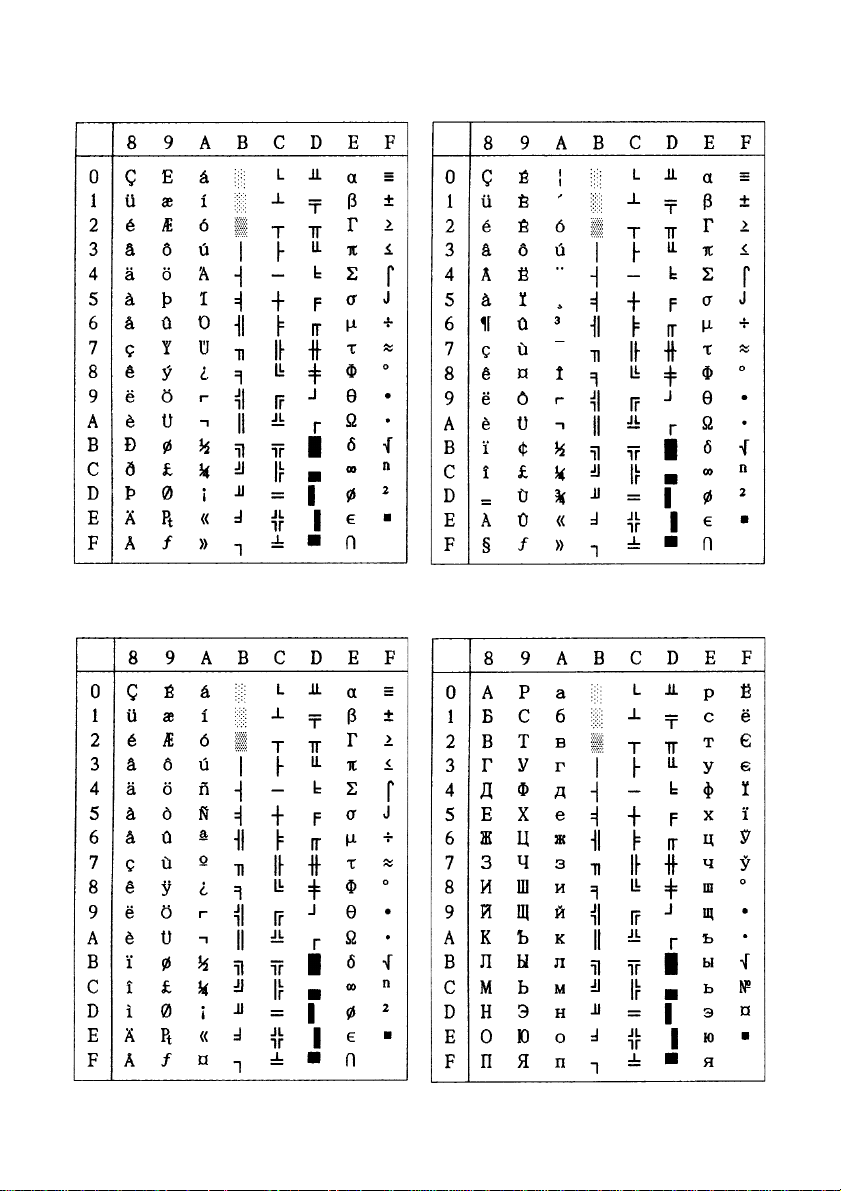
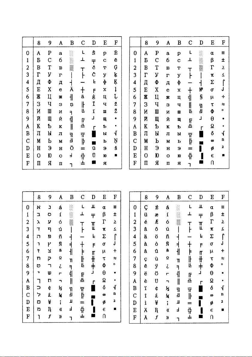
Appendix B: Character Sets
IBM Graphics Character Set #2
Code Page #437 (U.S.A.)
Italic Character Set #2
– 55 –
Page 61

IBM Graphics Character Set #1
Italic Character Set #1
– 56 –
APPENDIX
Page 62

Code Page #737 Code Page #772
Greek Lithuanian
Code Page #774 Code Page #850
Lithuanian Multi-lingual
Other characters are the same as those for Code Page #437.
– 57 –
Page 63

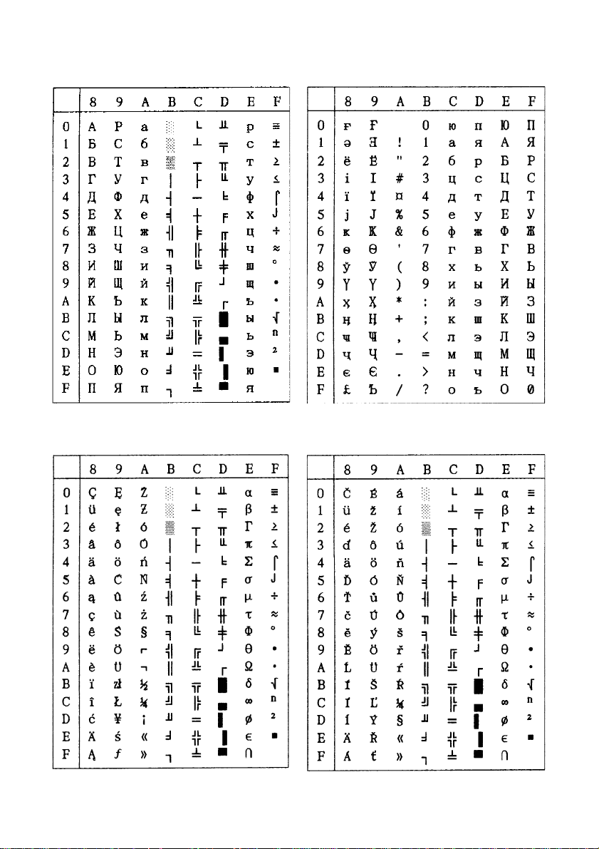
Code Page #851 Code Page #852
Greek Latin-2
Code Page #858 Code Page #860
Multi-lingual with Euro Portuguese
Other characters are the same as those for Code Page #437.
– 58 –
APPENDIX
Page 64
Code Page #861 Code Page #863
Icelandic Canadian French
Code Page #865 Code Page #866
Nordic Russian
Other characters are the same as those for Code Page #437.
– 59 –
Page 65

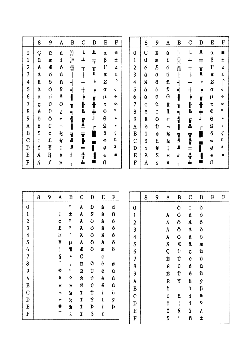
Code Page #869 Code Page #928
Greek Greek
Code Page #2001 Code Page #3001
Lithuanian-KBL Estonian-1
Other characters are the same as those for Code Page #437.
– 60 –
APPENDIX
Page 66
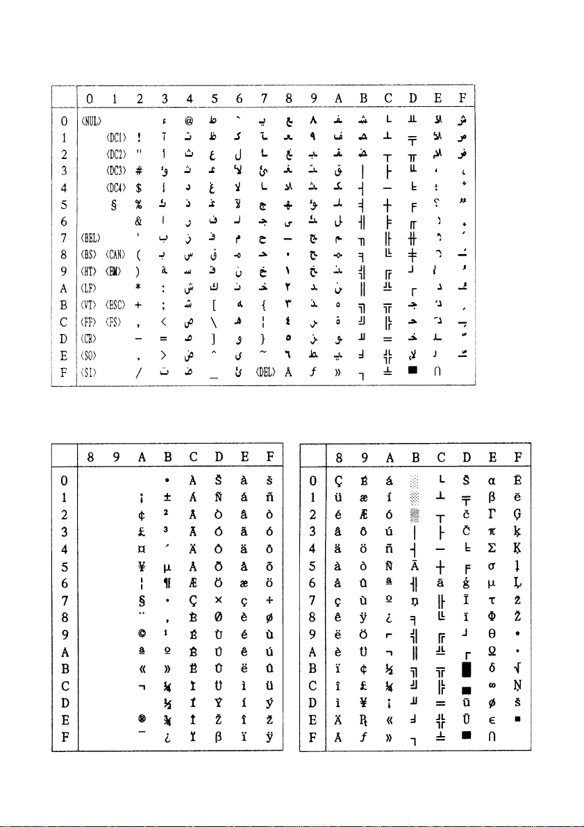
Code Page #1001
Arabic
Code Page #3002 Code Page #3011
Estonian-2 Lavian-1
Other characters are the same as those for Code Page #437.
– 61 –
Page 67
Code Page #3012 Code Page #3021
Lavian-2 Bulgarian
Code Page #3031 Code Page #3041
Hebrew Maltese
Other characters are the same as those for Code Page #437.
– 62 –
APPENDIX
Page 68
Code Page #3840 Code Page #3841
IIBM-Russian Gost
Code Page #3843 Code Page #3844
Polish CS2
Other characters are the same as those for Code Page #437.
– 63 –
Page 69
Code Page #3845 Code Page #3846
Hungarian Turkish
Code Page #3847 Code Page #3848
Brazil-ABNT Brazil-ABICOMP
Other characters are the same as those for Code Page #437.
– 64 –
APPENDIX
Page 70
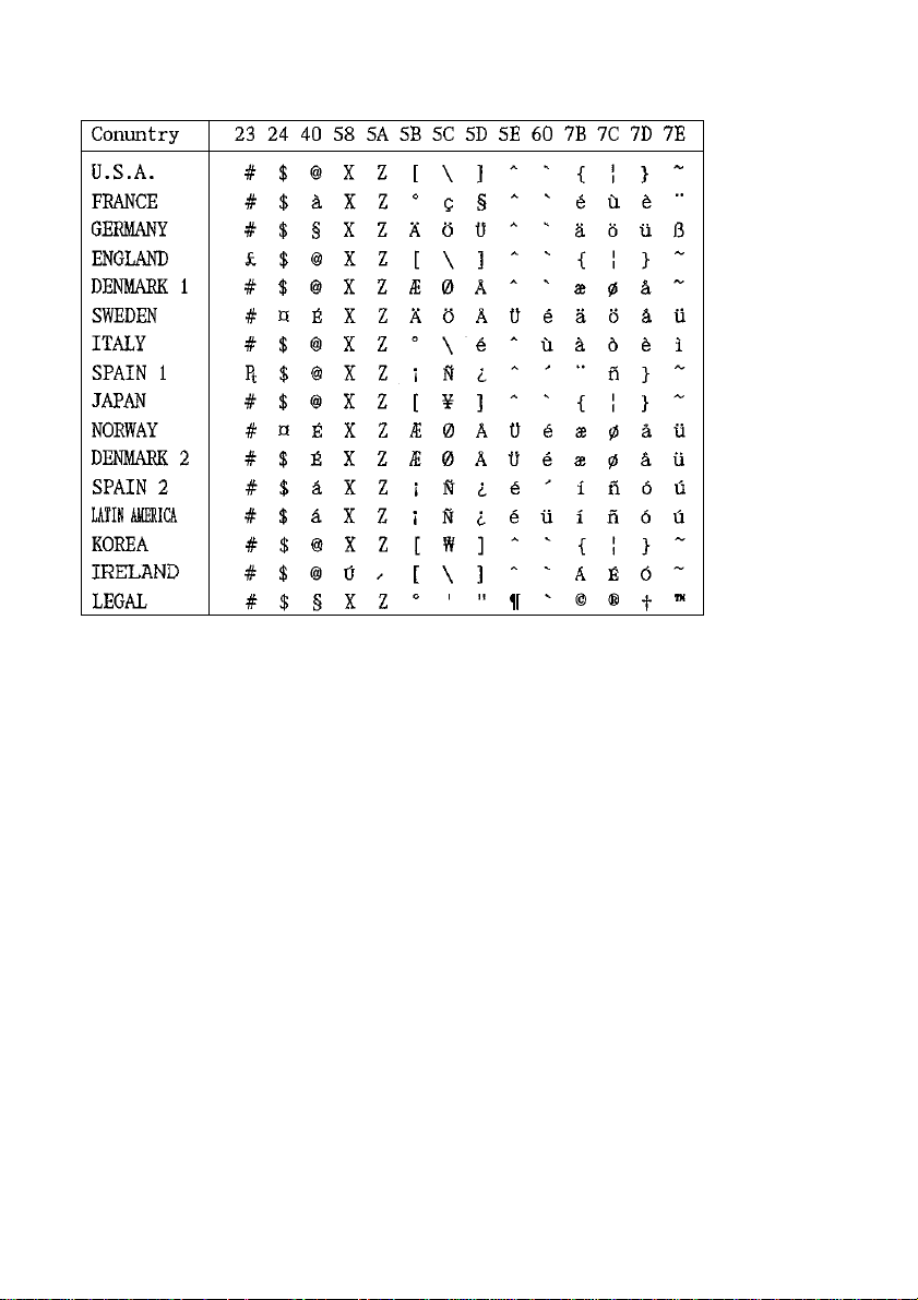
International Character Set
– 65 –
Page 71

Appendix C. Control Panel Operation Guide
: Push
: Hold
ON-LINE
OFF-LINE
POWER-ON
POWER
P.E.
TEAR OFF
SET/PARK
EJECT
MICRO FEED
Print mode
Panel lock (Print mode)
Panel Macro (Print mode & Panel Lock)
Set / Park / Eject Line Feed ON-LINE
Reverse
AUTO LOADING POSITION CHANGE MODE
Set top of form (TOF)
Buffer clear (1 Beep) / All reset (3 Beeps)
Hex dump mode Self test (Long) Self test (Short)
DOT ADJUSTMENT MODE
LINE FEED
FORM FEED
Tear off (Page)
Form Feed
Forward
EDS MODE
ON LINE
OFF-LINE
< Micro Paper Feed >
ENGLISH
EDS MODE
DOT ADJUSTMENT MODE
AUTO LOADING POSITION CHANGE MODE
BANK SW
EDS No.
Left Right
Reverse feed Forward feed
Save & Exit
– 66 –
ON / OFF
Print
Exit
Next
Previous
Exit
Paper loading
Factory settings & Exit
Page 72

STAR MICRONICS ASIA LTD.
HEAD OFFICE
Rm. 1901-6, 19/F., Enterprise Square Two,
3 Sheung Yuet Road, Kowloon Bay, Hong Kong
EUROPEAN OFFICE
C.P. 58, CH-6914 Carona,
Ticino, Switzerland
TEL: +852-2796-2727
FAX: +852-2799-9344
E-mail: smh@starhkg.com.hk
Web site: http://www.starhkg.com.hk/
TEL: +41-91-630.62.08
FAX: +41-91-630.62.09
E-mail: Gaudenz.Juon@dial.eunet.ch
 Loading...