

Page 1
USERS MANUAL
LC24-200cc)muR
LC24-200
ZBL 80821757
Page 2

LC24-200
LC24-200
COLOUR
USERS MANUAL
NOT INTENDED FOR SALE
Page 3
S
T d c p m c t m r i
r P O 2 9 a m “ 2 e
s f t t ap d ( o a w o i m C
B r a w 0 p 1 P O
1
t d o c w o d w a s o t a
a“ ( A a w P O 2 c
s m c w C B l a w 0 p 1
s p a w p a
P O 2
a r t o f w d o a s w b t
p w a p m w a m “ 2
M N I O G J 1 s p l
o p e l t d a 7
a s a o p m G
T A
L X L S S R S M C L
M C
M B M M C
P P P X P X P I B
L L S E C
N
● r r R p t m f w w
S e p f
● c t m s c w n
● e h b m t a c t m p
H s e d S w g a b i t
o a n S a r e m
@Copyr19StMicrCoLt
Page 4
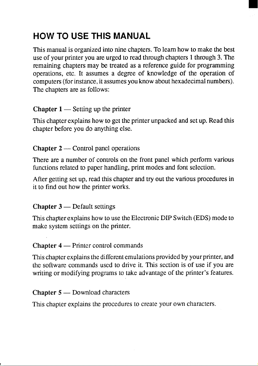
HOW TO USE THIS MANUAL
Thismanualis organizedintonine chapters.Tolearnhowtomakethebest
useof yourprinteryouareurgedtoreadthroughchapters1through3.The
remainingchaptersmay be treatedas a referenceguidefor programming
operations,etc. It assumesa degreeof knowledgeof the operationof
computers(forinstance,itassumesyouknowabouthexadecimalnumbers).
Thechaptersare as follows:
Chapter 1— Settingup theprinter
Thischapterexplainshowtogettheprinterunpackedandsetup. Readthis
chapterbeforeyoudo anythingelse.
Chapter 2— Controlpaneloperations
There are a numberof controlson the frontpanelwhichperformvarious
functionsrelatedto paperhandling,printmodesand fontselection.
Aftergettingsetup, readthischapterandtry outthe variousproceduresin
it to find outhowtheprinterworks.
Chapter 3 — Defaultsettings
Thischapterexplainshowtousethe ElectronicDIPSwitch(EDS)modeto
makesystemsettingsontheprinter.
Chapter 4— Pnntcr controlcommands
Thischapterexplainsthedifferentemulationsprovidedbyyourprinter,and
the softwarecommandsusedto drive it. This sectionis of use if you are
writingor modifyingprogramsto takeadvantageoftheprinter’sfeatures.
Chapter 5 — Downloadcharacters
Thischapterexplainstheproceduresto createyourowncharacters.
Page 5
Chapter 6— MS-DOSand yourprinter
Sincethe PC or PC-AT family of computersnmningunder MS-DOSis
currentlythe most popularconfigurationof microcomputer,we have includedafewhints andtipsto helpyouuseyourprinterwith suchsystems.
SincevirtuallyallPCsaresoldwithaMicrosoftBASICinteqxeter,wehave
also included some hints, and a sample program in this language to
demonstratethecapabilitiesof theprinter.
Chapter 7 — Troubleshootingandmaintenance
Thissectiongivesachecklistofpointstocheckifyourpnnterisnotworking
in the expectedway.It also includesdetailsof someroutinemaintenance
operationsyou cancarryoutyourself.Itisnot,however,acompleteservice
manual.Callaqualifiedserviceengineerif youareunsureofyourabilityto
carryout any maintenanceorservicingoperations.
Chapter 8 — Specifications
This sectiongivesthe specificationsof yourprinter.
Chapter 9 — Charactersets
Thesechartsshowthe differentcharactersets available.
Page 6
I
FEATURESOF THE PRINTER
Thisprinterhas a fullcomplementoffeatures,makingitanexcellentpartner
for a pemcmalcomputer.It supportsthe IBM/Epsonprintercommandsand
charactersets,enablingit to pMt just aboutanythingyourcomputercan
generate,bothtextandgraphics.Someofitsmainfeatms ruethefollowing:
● Versatilepaperhandling
Singlesheets,fanfold forms, and multi-pm forms (up to 5-ply) rue all
accepted,andyoucanuseeitherpush@l tmctoror frictionfeed.(Youcan
load fanfoldforms fium the rear with push tractor,or fanfoldformsand
multi-pan forms fmm the bottom with pull tractor.)A special feature
enablesyou to keep fanfoldformsparkedin readinesswhileprintingon
other paper.
● Six bright colors
MageM cyan,violet,yellow,orange,and~n add a colordimensionto
yourprintedoutputby the colorversionprinter.
● Largevarietyof fontsand sizes
Theprinterhasonedraftfon~oneHigh+eed DraftfontandfiveLQ fonts
(Romm SanSerif,Courier,Pmtige and Script),italicsfor all styles,plus
condensedprint,bold print,double-sizedpnn~ and quadruple-sizedprint.
● Extensivesoftwaresuppofl
Sinceit is compatiblewiththeEpsonandIBMprintm, it workswithany
softwruethat supportsthoseprintem.That includesmost woti-pmcesdng
and graphicsprograms,spread-sheets,and integratedsoftwarepackages.
. Easy operation
Indicatordisplaysand beep tonesprovideimmediate,easy to understand
feedbackwhenyoup~s thebuttonsonthecontrolpanel.Thefivebuttons
can operatein combinationsto performa suqxisingvarietyof functions,
including micm-alignment.
● Easy care and maintenance
The ribboncartridgecan be replacedin secondsthe print head in a few
minutes.
Page 7
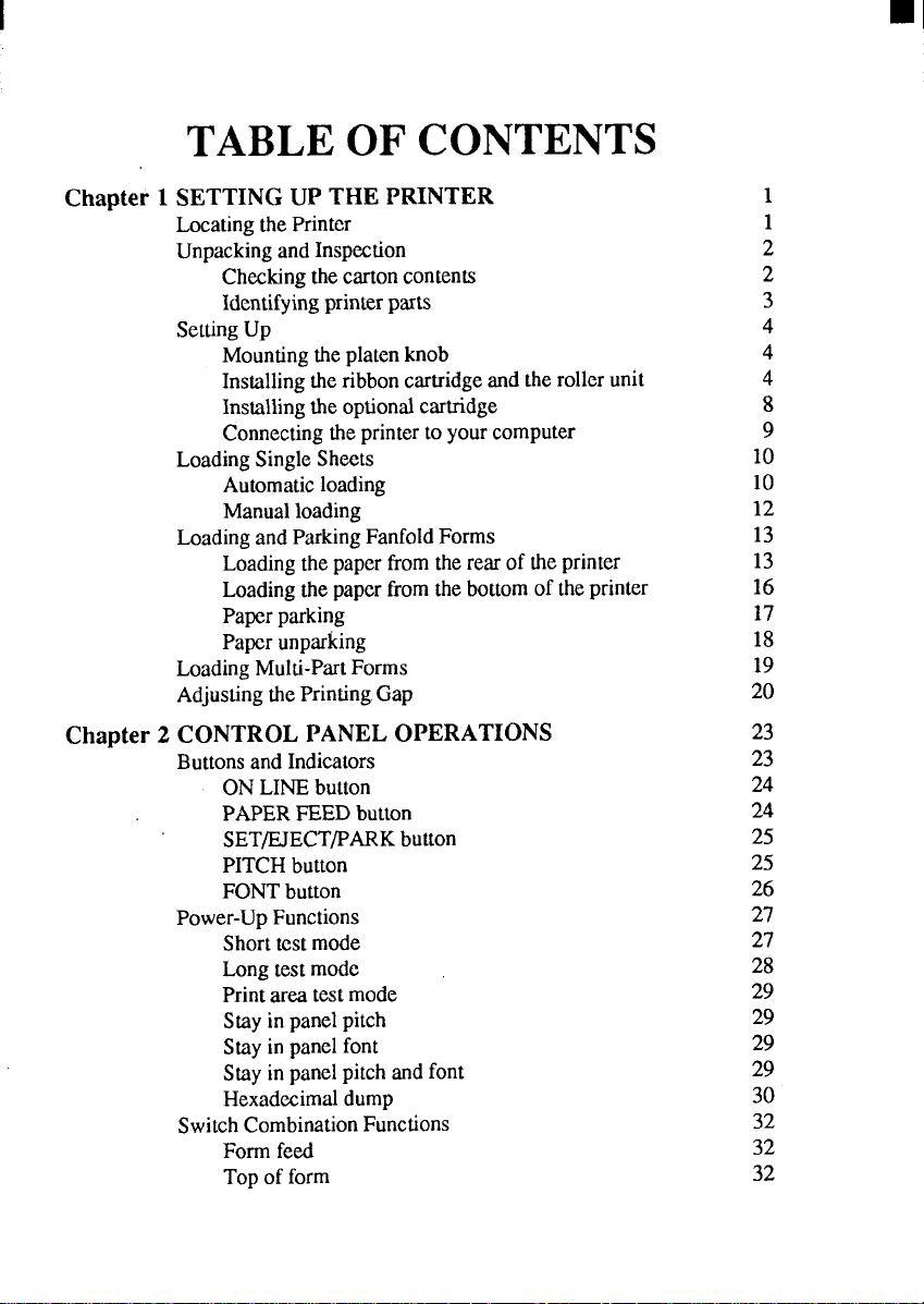
TABLE OF CONTENTS
Chapter 1 SETTING UP THE PRINTER
LocatingthePrinter
UnpackingandInspection
Checkingthecartoncontents
Identifyingprinterparts
SettingUp
Mountingtheplatenknob
Installingtheribboncartridgeandtherollerunit
Installingtheoptionalcartridge
Connectingtheprintertoyourcomputer
LoadingSingleSheets
Automaticloading
Manualloading
LoadingandParkingFanfoldForms
Loadingthepaperfromtherearoftheprinter
Loadingthepaperfromthebottomoftheprinter
Paperparking
Paperunparking
LoadingMulti-PartForms
AdjustingthePrinting.Gap
Chapter 2 CONTROL PANEL OPERATIONS
ButtonsandIndicators
ONLINEbutton
PAPERFEEDbutton
SET/EJECT/PARKbutton
PITCHbutton
FONTbutton
Power-UpFunctions
Shorttestmode
Longtestmode
Printareatestmode
Stayinpanelpitch
Stayinpanelfont
Stayinpanelpitchandfont
Hexadecimaldump
SwitchCombinationFunctions
Formfeed
Topofform
1
1
2
2
3
4
4
4
8
9
10
10
12
13
13
16
17
18
19
20
23
23
24
24
25
25
26
27
27
28
29
29
29
29
30
32
32
32
Page 8
Forwardmicro-feed
Reversemicro-feed
Changingtheautoloadingvalue
Clearingthebuffer/Allreset
Selectingtheprintcolor
Storemacrodefinition
33
33
33
34
35
35
Chapter 3 DEFAULT SETTINGS
HowtosettheEDSmode
FunctionsoftheEDSsettings
Bidirectionaltest/Adjustmentmode
Chapter 4 PRINTER CONTROL COMMANDS
FontControlCommands
CharacterSetCommands
CharacterSizeandPitchCommands
VerticalPositionCommands
HorizontalPositionCommands
GraphicsCommands
DownloadCharacterCommands
ColorSelectionCommandes
OtherPrinterControlCommands
Chapter 5 DOWNLOAD CHARACTERS
DefiningYourOwnCharacterswithStandardMode
Assigningthecharacterdata
Assigninga valueofcharacterspace
Sampleprogram
DefiningYourOwnCharacterswithIBMMode
Assigningthedownloadcharacterset
Assigningthecharacterdotpattern
AssigningtheIndexTabledata
Sampleprogram
3-7
37
38
43
45
46
52
55
61
68
73
76
81
81
85
85
86
87
88
90
90
91
93
94
Chapter 6 MS-DOS ANDYOUR PRINTER
InstallingApplicationSoftwarewithYourPrinter
EmbeddingPrinterCommands
ProgrammingthePrinterwithDOSCommands
ProgrammingwithBASIC
Howtheprogramworks
97
97
98
100
103
108
Page 9
Chapter 7 TROUBLESHOOTING AND MAINTENANCE
Troubleshooting
Powersupply
Printing
Paperfeeding
Maintenance
ReplacingthePrintHead
111
111
112
112
114
117
117
Chapter 8 SPECIFICATIONS
Chapter 9 CHARACTER SETS
StandardCharacterSet#1
StandardCharacterSet#2
IntemationaJCharacterSets
IBMCharacterSet#2
Codepage#437(U.S.A.)
Codepage#850(Multi-1ingual)
Codepage#860(Portuguese)
Codepage#861(Icelandic)
Codepage#863(CanadianFrench)
Codepage#865(Nordic)
IBMCharacterSet#1
IBMSpecialCharacterSet
ProportionalSpacingTable
INDEX
COMMANDSUMMARY
119
123
124
126
127
128
128
130
131
132
133
134
135
136
137
149
153
Page 10
I
chapter 1
SETTING UP THE PRINTER
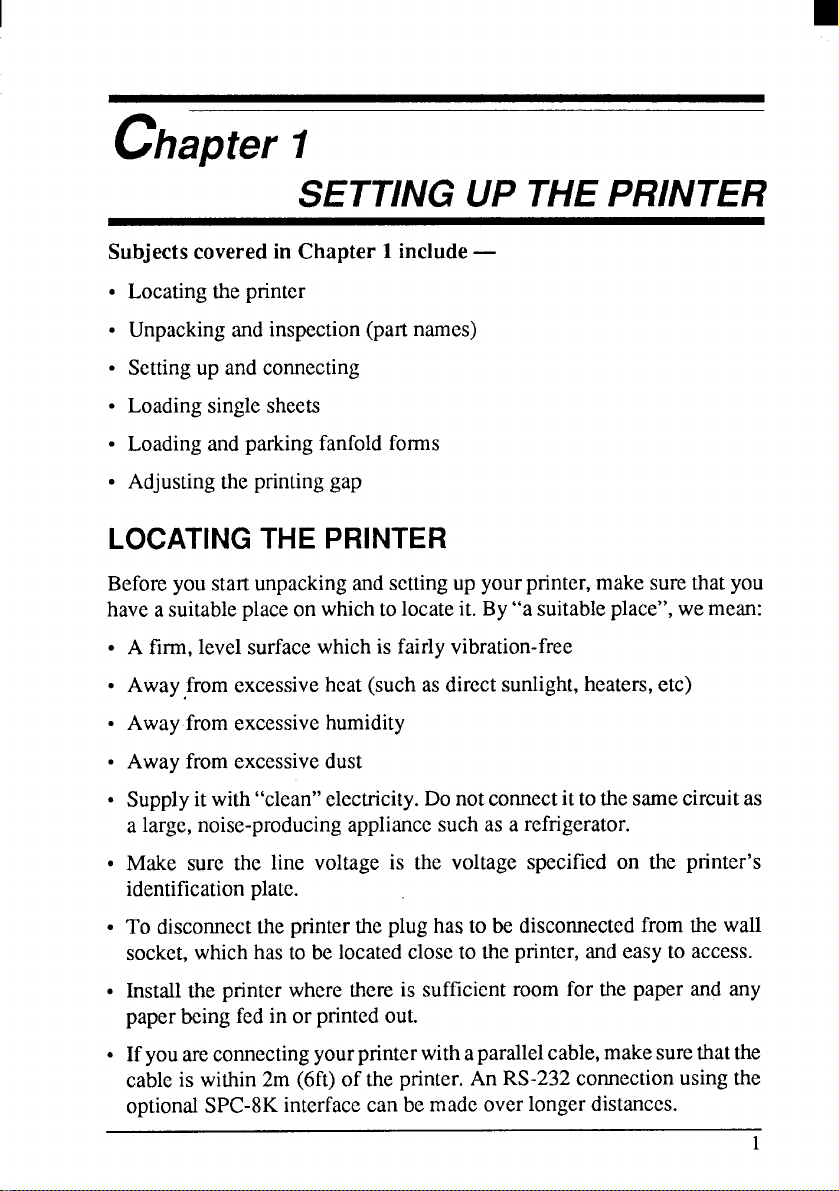
Subjects covered in Chapter 1 include —
●
Locatingthe printer
●
Unpackingandinspection(partnames)
✎
Settingup andconnecting
✎
Loadingsinglesheets
✎
Loadingand parkingfanfoldforms
✎
Adjustingtheprintinggap
LOCATING THE PRINTER
Beforeyou startunpackingandsettingup yourprinter,makesurethatyou
haveasuitableplaceonwhichtolocateit. By“a suitableplace”,wemean:
●
A firm,levelsurfacewhichis fairlyvibration-free
●
Awayfrom excessiveheat(suchas directsunlight,heaters,e(c)
✎
Awayfromexcessivehumidity
✎
Awayfromexcessivedust
●
Supplyitwith“clean”electricity.Donotconnectittothesamecircuitas
a large,noise-producingappliancesuchas a refrigerator.
●
Make sure the line voltage is the voltage specified on the printer’s
identificationplalc.
✎
To disconnecttheprintertheplug hasto be disconnectedfromthe wall
socket,whichhastobe locatedcloseto theprinter,andeasyto access.
●
Installthe printerwherethereis sufficientroomfor the paper and any
paperbeingfedin orprintedout.
●
Ifyouareconnectingyourprinterwithaparallelcable,makesurethat the
cableis within2m (6ft)of the printer.An RS-232connectionusingthe
optionalSPC-8Kinterfacecan bemadeoverlongerdistances.
1
Page 11
UNPACKINGAND INSPECTION
Checking the carton contents
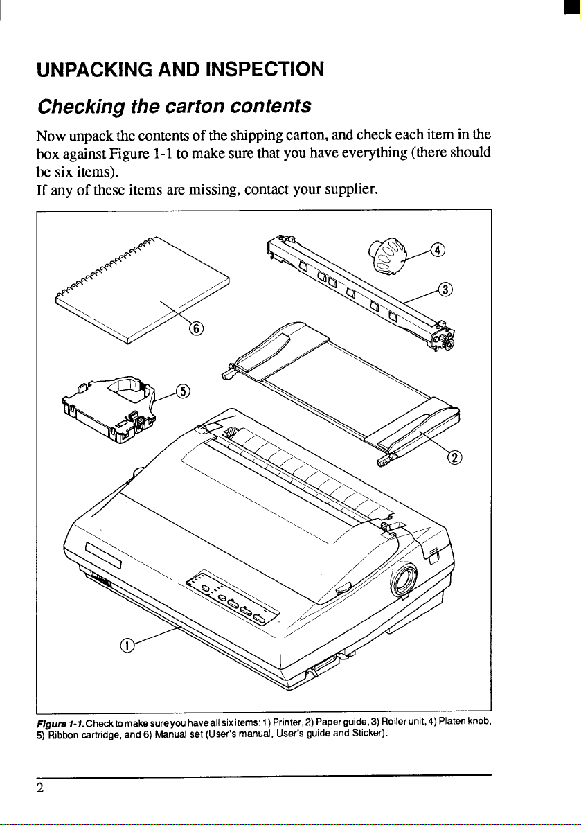
Nowunpackthe contentsofthe shippingcarton,andcheckeachiteminthe
boxagainstFigure1-1tomakesumthatyouhaveeverything(thereshould
be six items).
If anyof theseitemsammissing,contactyoursupplier.
F@ms l-1. Checktomakesureyou haveallsixitems: 1)Printer,2) Paperguide,3) Roller unit,4) Platenknob,
5) Ribbon cartridge, and 6) Manual set (User’s manual, User’s guide and Sticker).
2
Page 12

The optionalaccessorieswhichyoumayhaveorderedwithyourprinterare:
● Fontcartridges(FC-lZ, FC-2Z,FC-3Z,FC-4Z)
● RAMcartridge(RC-32Z)
● Serial-Parallelconverter(SPC-8K)
● Automaticsheetfeeder(SF-1ODQ)
. Rollpaperholder(RH-1OZ)
Identifying printer parts
Make an external inspectionof the printer. Note the locations of the
followingpartsin Figure 1-2.
I
I
Figure 1-2.The printer’s external psrts
Roller unit:
Releaselever:
holds the paperagainstthe platen.
releasesthe platen.Thislevermustbebackfor
single sheets,andforwardforfanfoldforms.
Top cover:
Rear cover:
Entry slot:
Control panel:
Power switch:
protectsthe printheadandotherinternalparts.
protectsthetractorfeedmechanism.
for insertingsinglesheetsof paper.
controlsvariousprinterIimctions.
turnspoweron andoff.
Interface connector: for connectingthecomputerto theprinter.
3
Page 13
SEITING UP
Placethe printerin the desiredlocation,andremoveall packingmaterial
from insidethe top cover. This packingmaterialis intendedto prevent
damagetotheprinterwhilein transit.Youwillwanttokeepallthepacking
material,alongwiththe printercarton,incaseyouhavetomovetheprinter
to anewlocation.
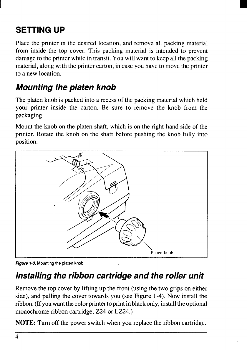
Mounting theplaten knob
Theplatenknobispackedintoarecessof thepackingmaterialwhichheld
your printer inside the carton. Be sure to remove the knob from the
packaging.
Mountthe knobontheplatenshaft,whichis ontheright-handsideof the
printer.Rotate the knob on the shaft beforepushingthe knob fully into
position.
P1.itenhnob
F/gun?1-3. Mounting the platen knob
Installing the ribbon cartridge and the roller unit
Removethetopcover by liftingupthefront(usingthe twogripsoneither
side),andpullingthe covertowardsyou (seeFigure 1-4).Nowinstallthe
ribbon.(Ifyouwantthecolorprintertoprintinblackonly,installtheoptional
monochromeribboncartridge,Z24orLZ24.)
NOTE: Turnoff thepowerswitchwhenyoureplacetheribboncartridge.
4
Page 14
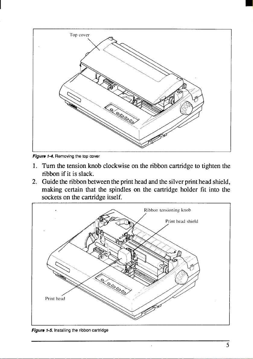
Flgum 74. Removing the top cover
1. Turnthe tensionknobclockwiseonthe ribboncartridgeto tightenthe
ribbonifit is slack.
2. Guidethenbbonbetweenthepnnthead andthesilverprintheadshield,
making certain that the spindleson the cartridgeholder fit into the
socketson the cartridgeitself.
Figure 1-5. Installing the ribbon cartridge
5
Page 15
I
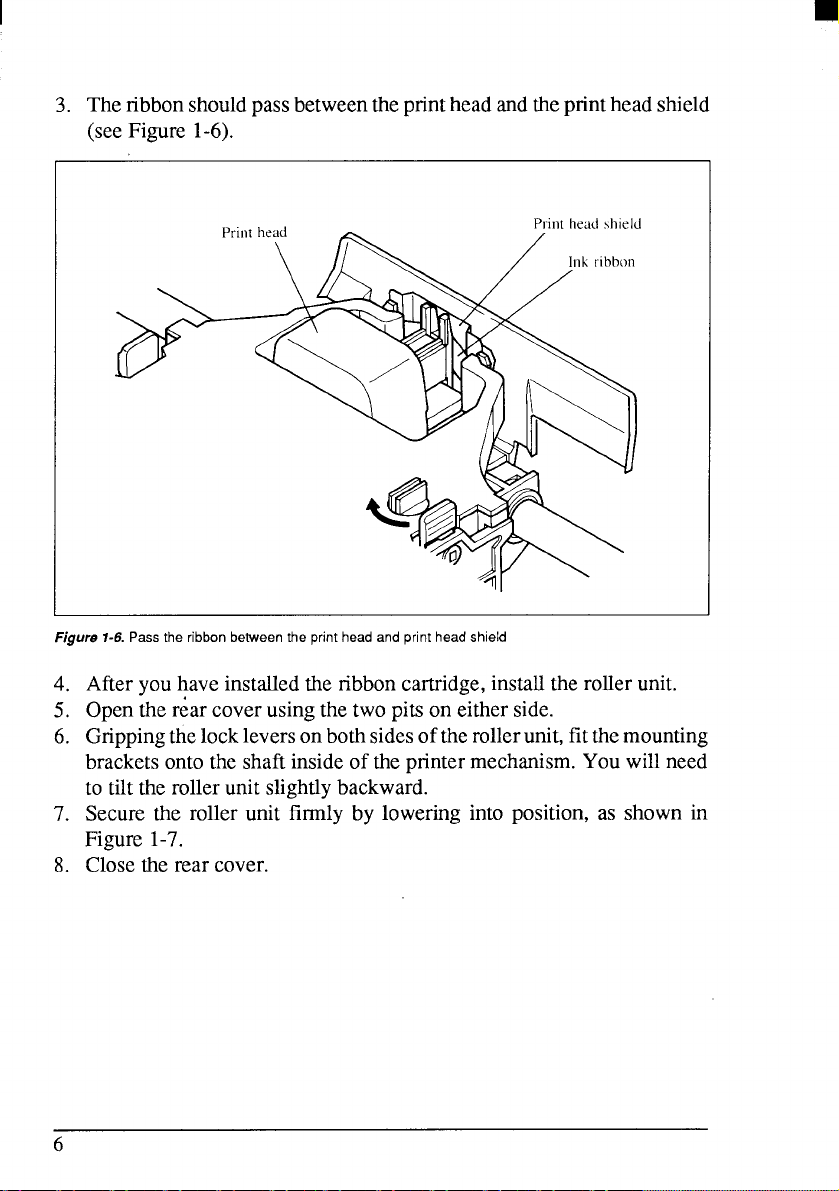
3. Theribbonshouldpassbetweentheprintheadandtheprintheadshield
(seeFigure 1-6).
~
Figure 1-6. Passthe ribbon between the print head and print head shield
Afteryouhaveinstalledthe ribboncartridge,installtherollerunit.
4.
5,
Openther;ar coverusingthetwo pitson eitherside.
6.
Grippingthe lockleversonbothsidesoftheroller unit,fitthemounting
bracketsontothe shaftinsideof theprintermechanism.Youwillneed
to tilttherollerunitslightlybackward.
7.
Securethe roller unit firmly by loweringinto position,as shown in
Figure1-7.
8.
Closethe rear cover.
6
Page 16
I
Roller
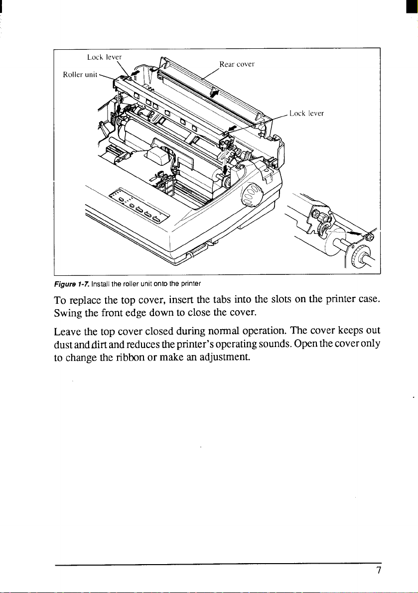
Figure i-7. Install the roller unit onto the printer
To replacethe top cover,insertthe tabs intotheslotson the printercase.
Swingthefrontedgedownto closethe cover.
Leavethetopcoverclosedduringnormaloperation.Thecoverkeepsout
dustanddirtandreducestheprinter’soperatingsounds.Openthecoveronly
to change the ribbonormakean adjustment.
Page 17
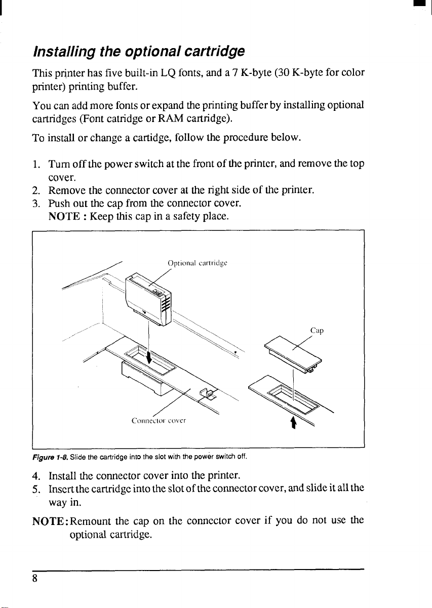
Installing the optional cartridge
Thispr@terhasfivebuilt-inLQfonts,anda7 K-byte(30K-bytefor color
printer)printingbuffer.
Youcanaddmorefontsorexpandtheprintingbufferbyinstallingoptional
cartridges(Fontcatndgeor RAMcartridge).
To installorchangea cartidge,followtheprocedurebelow.
1. Turnoffthepowerswitchatthefrontoftheprinter,andremovethetop
cover.
2. Removetheconnectorcoveratthe rightsideof the printer.
3. Push outthecap fromtheconnectorcover.
NOTE : Keepthiscap in a safetyplace.
Optional cartl-i(igc
Figurs 1-8. Slide the csrtridge imo the slot with the power switch off.
4. Installtheconnectorcoverintotheprinter.
5. Inscrtthecartridgeintotheslotofthecmnnectorcover,andslideitallthe
wayin.
NOTE:Remount the cap on the comcctor cover if you do not use the
optionalcartridge.
8
Page 18
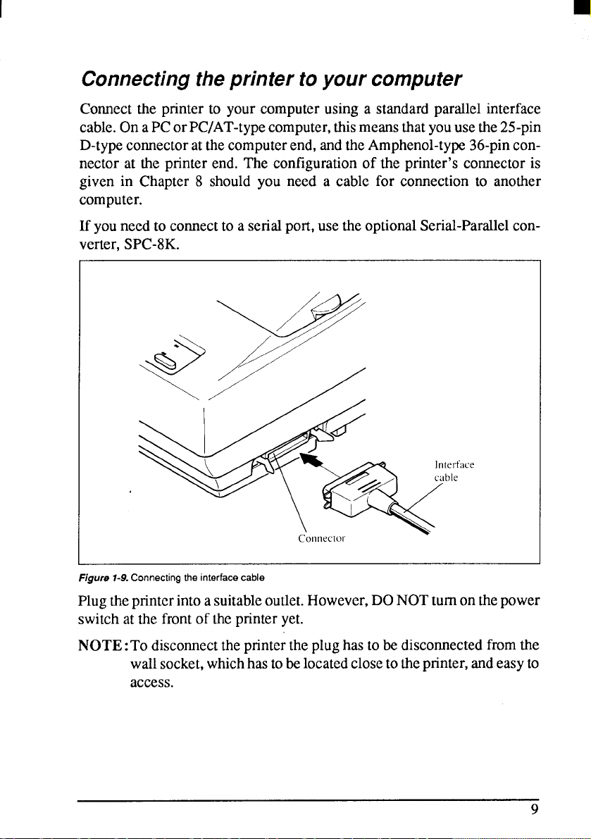
Connecting the printer to your computer
Connect the printerto your computerusing a standardparallelinterface
cable.OnaPCorPC/AT-typecomputer,thismeansthatyouusethe25-pin
D-typeconnectoratthecomputerend,andtheAmphenol-type36-pinconnector at the printer end. The configurationof the printer’sconnectoris
given in Chapter 8 shouldyou need a cable for connectionto another
computer.
If youneedto comect to a serialport,usetheoptionalSerial-Parallelconverter,SPC-8K.
1
Figure 1-9.Connecting the interface cable
Plugthe printerintoasuitableoutlet.However,DONOTturnonthepower
switchatthefrontof the printeryet.
NOTE: To disconnecttheprintertheplughastobedisconnectedfromthe
wallsocket,whichhastobelocatedclosetotheprinter,andeasyto
access.
Page 19
LOADING SINGLE SHEETS
Thissectionwilltakeyouthroughtheproceduresforloadingsinglesheets
of paper.
Ifyouareusingtheoptionalautomaticsheetfeeder(SF-10DQ),referto the
ASFinstructionbooklet.
Automatic loading
Singlesheetscanbe loadedmanuallywiththepoweroff,or automatically
withthepwer on. We willstarttheeasy waywithautomaticloading.
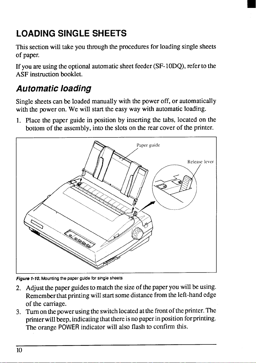
1. Placethe paperguidein positionby insertingthetabs,locatedon the
bottomof the assembly,intotheslotson the rearcoveroftheprinter.
lever
Figure 1-10. Mounting the paper guide for single sheets
2. Adjustthepaperguidestomatchthesizeofthepaperyouwillbeusing.
Rememberthatprintingwillstartsomedistancefromtheleft-handedge
of the carriage.
3. Tumonthe powerusingtheswitchlocatedatthefrontofthe printer.The
printerwillbeep,indicatingthatthereisnopaperinpositionforprinting.
Theorange
POWER indicatorwillalsoflash to confirmthis.
10
Page 20
4.
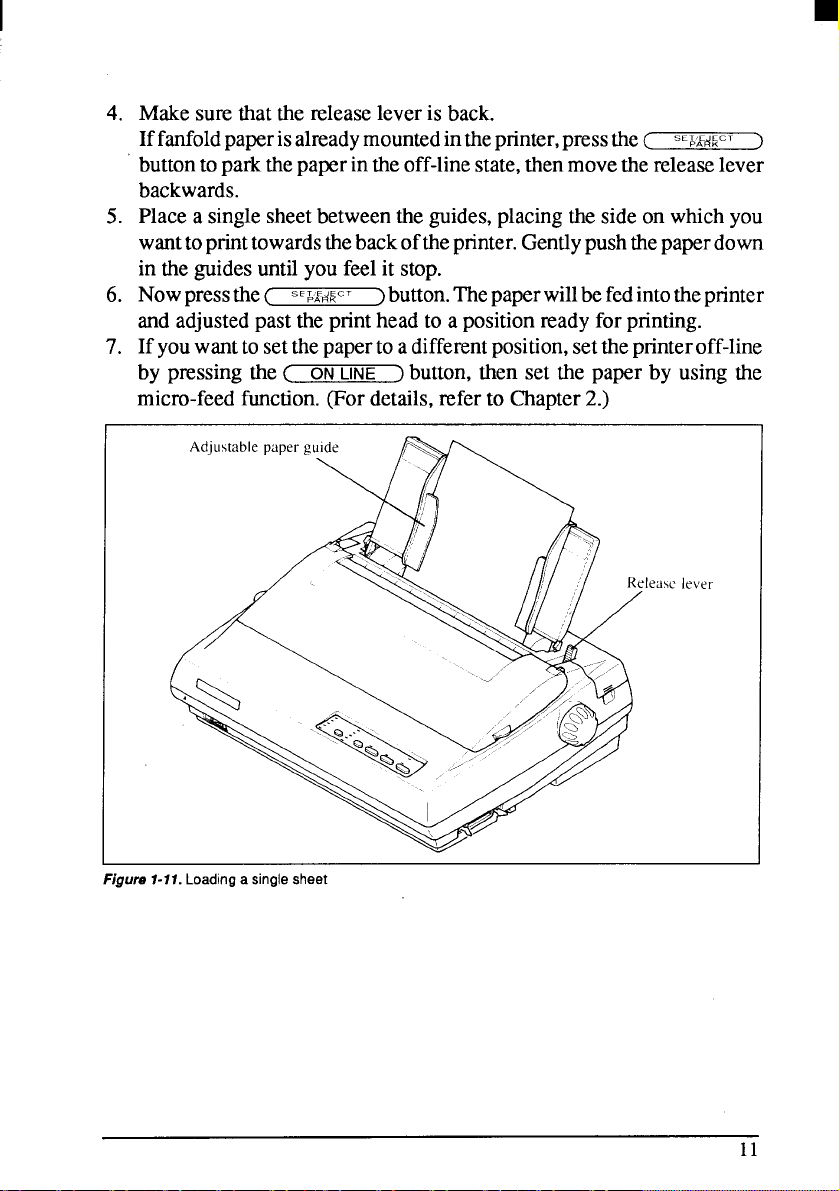
Makesurethatthereleaseleveris back.
Iffanfoldpaperisalreadymountedintheprinter,pressthe(
sc&AE~~cT
buttontoparkthepaperintheoff-linestate,thenmovethereleaselever
backwards.
Placea singlesheetbetweentheguides,placingthesideon whichyou
5.
wanttoprinttowardsthebackoftheprinter.Gentlypushthepaperdown
in theguidesuntilyoufeelit stop.
Nowpressthe(
6.
sE&~+cT
)button.Thepaperwillbefedintotheprinter
andadjustedpasttheprintheadto a positionreadyforprinting.
Ifyouwanttosetthepapertoadifferentposition,setthepnnteroff-line
7.
by pressingthe( ON
LINE ) button,~en set the paper by using the
micro-feedfunction.(Fordetails,referto Chapter2.)
1
)
Figure 1-17. Loading a single sheet
11
Page 21
Manual loading
Itisalso,possibletoloadpapermanuallywhiletheprinter’spowerisoff.The
procedureis:
1. Placethe paperguidein positionby insertingthe tabs,locatedon the
bottomof theassembly,intotheslotson the rear coverof theprinter.
2. Check thatprinter powerisoff andthe release lever isback.
3. Adjust the paper guidesto matchthesize of paper you will be using.
Rememberthatprintingwillstartsomedistancefromtheleft-handedge
of thecarnage.
4. Placea singlesheetbetweenthe guides,placingthe sideon whichyou
wanttoprinttowardsthebackoftheprinter.Gentlypushthepaperdown
in theguidesuntilyou feelit stop.
5. Turn theplatenknobclockwiseuntilthefrontedgeof the papercomes
outfromunderthetop cover.
6. If the paper is not straight, move the release lever forward, then
straightenthepaperby hand andmovethereleaseleverback.
12
Page 22

I
LOADING AND PARKINGFANFOLD FORMS
Fanfold forms have holes alongthe sides and perforationsbetween the
sheets.Theyare also calledsprocketforms,punchedforms,or just plain
“computerpaper”.Thisprinteracceptsformsupto 10”wide.Thissection
willtakeyou throughtheproceduresfor loading,parkingandunparking
fanfoldforms.
NOTE:To get good line-feeding,put l-inch space (non-printingarea)
aroundaperforation.
Loading the paper from the rear of the printer
Youcanloadthefanfoldpapereitherfromtherearorfromthebottomofthe
printer.If youaregoingtoloadthepaperfromthebottom,refertothenext
section.
Placeastackoffanfoldpaperbehindandatleastonepage-lengthbelow
1.
theprinter.
Turnthe printer’spowerOFF.
2.
Pushthereleaseleverforward.Thishastheeffectofreleasingthepaper
3.
fromtheplatenroller,and engagingthetractorfeed.
4.
Removethepaperguideand putit asideforthemoment.
5.
Removetherearcoverusingthetwopitsoneitherside,andpushbackwardsas in Figure1-12.
Figure 1-12. Removing the rear cover
13
Page 23
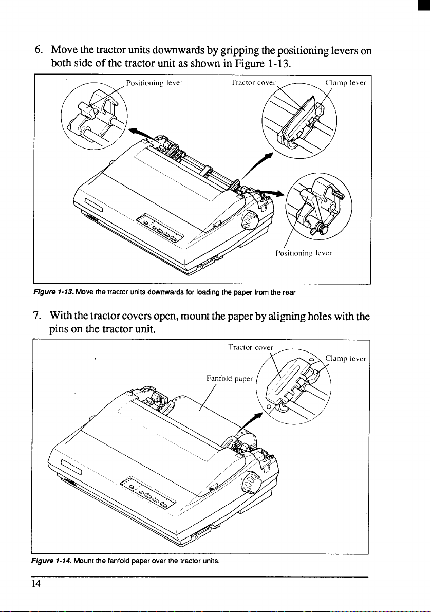
6. Movethetractorunitsdownwardsbygrippingthe positioningleverson
bothsideofthetractorunitas shownin Figure 1-13.
Figure 1-13. Movethe tractorunits dawnwards for loading the paper from the rear
7. Withthetractorcoversopen,mountthepaperbyaligningholeswiththe
pinson the tractorunit.
-. . .. .. ., . .
rlgws 7-74. rvmun~tne ranrola paper over me Iraclor urms.
14
Ieve
Page 24
Adjustthe spacingofthetractorunitsbyslidingthemalongthebar,using
8.
the clamp lever at the back of each unit to release and lock them in
position.Whentheclampleverisup,theunitisreleased,andwhenitis
down,theunitislocked.
Nowclosethetractorcovers,againmakingsurethatthepaperholesare
9.
alignedwiththepinsonthe tractorunits.Iftheyare notal;fied properly,
youwillhaveproblemswithpaperfeeding,possiblyresultingintearing
andjammingofthepaper.
10.Turnonthepowerusingtheswitchlocatedatthefrontoftheprinter.The
printerwillbeep,indicatingthatthepaperis not yet fullyloaded.The
orange
11.Nowpressthe c
POWER indicatorwill alsoflashto confirmthis.
s.pd~c,
>button.Thepaper willbefedandadjusted
pastthe printheadto a positionreadyforprinting.
12.If youwanttosetthepapertoadifferentposition,settheprinteroff-line
by pressingthe<
ON LINE
button,then set the paper by using the
]
micro-feedfunction.(Fordetails,referto Chapter2.)
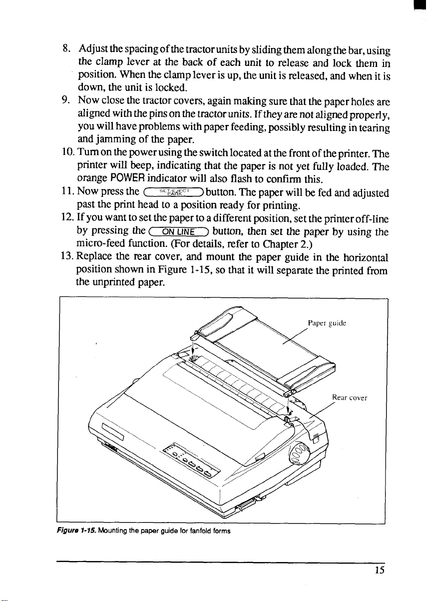
13.Replacethe rear cover, and mountthe paper guidein the horizontal
positionshownin Figure 1-15,so that it willseparatethe printedfrom
the unprintedpaper.
I
Figure 1-15. Mounting the papar guide for fanfold forms
cover
15
Page 25
Loading thepaper from the bottom of the printer
You caq load the fanfoldpaper from the bottomof the printer with the
followingprocedure.
1. Removethetop coverandthe rollerunit.
2. Opentherearcoverusingthetwopitsatthe side,andpushbackwards.
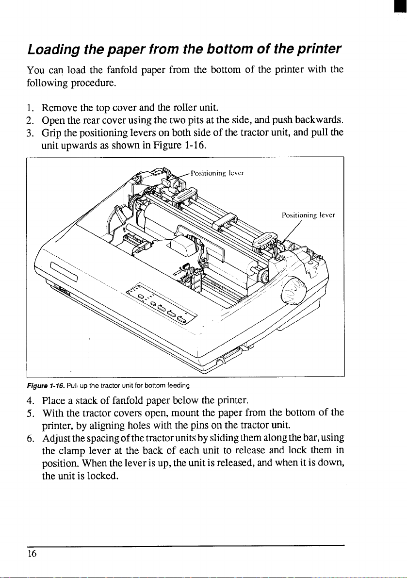
3. Gripthepositioningleverson bothsideof thetractorunit,andpullthe
uni;upwardsas showninFigure 1-16.
Figure 1-16. Pull up the tractor unit for bottom feeding
Placea stackof fanfoldpaperbelowtheprinter.
4.
Withthe tractorcoversopen,mountthepaper fromthe bottomof the
5.
printer,by aligningholeswiththepinson the tractorunit.
6.
Adjustthespacingofthetractorunitsbyslidingthemalongthebar,using
the clamp lever at the back of each unit to release and lock them in
position.Whentheleverisup,theunitisreleased,andwhenitisdown,
theunitislocked.
16
Page 26
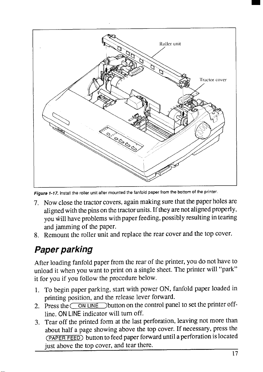
Figure 7-17. Install the roller unit after mounted the fanfold paper from the bottom of the printer.
7. Nowclosethetractorcovers,againmakingsurethatthepaperholesare
alignedwiththepinsonthetractorunits.Iftheyarenotalignedproperly,
youwillhaveproblemswithpaperfeeding,possiblyresultingintearing
andjammingof thepaper.
8. Remounttherollerunit andreplacetherear coverandthe top cover.
Paper parking
Afterloadingfanfoldpaperfromtherearof theprinter,youdonothaveto
unloadit whenyouwantto printon a singlesheet.Theprinterwill“park”
it for youif youfollowtheprocedurebelow.
1. To beginpaperparking,start withpowerON,fanfoldpaperloadedin
printingposition,andthe releaseleverforward.
LINE )buttonon thecontrolpanel to settheprinteroff-
2. Pressthe(
line.ON
3. Tear off theprintedformat thelast perforation,leavingnot morethan
abouthalf a page showingabovethe top cover.If necessary,pressthe
(PAPER FEED> buttontofeedpaper forwarduntilaperforationislocated
just abovethetopcover,andtearthere.
ON
LINE indicatorwillturnoff.
17
Page 27
4. Pressthe(
s,&/Ae#~cT
J buttononthe controlpanel.
Theprinterwillautomaticallyfeedthefanfoldformbackwarduntilthe
paperis completelyfreeoftheplaten.
5. Move the releaselevertotheback.
6. Mountthepaperguidein theuprightposition.
Now you can load single sheets either automaticallyor manually, as
explainedpreviously.The fanfoldpaperremainsparkedatthe backofthe
printer.
NOTE: You cannot park the fanfoldpaperif youhaveloadedit fromthe
bottomof the printer.
Paper unparking
Whenyouwantto resumeusingfanfoldpaper,theprocedureisas follows.
1. Removeallsinglesheetsfromtheprinter.
2. Mountthe paperguide in the horizontalposition.
3. Move the releaseleverto the front.
4. Pressthe (
parkedfanfoldpaperbackintopositionforprinting.
NOTE: Theprinterbeepsintermittentlyifyoumovethereleaseleverwhile
thepaperis loaded.
SE~/AE~~CT
button.Theprinterwillautomaticallyfeedthe
>
18
Page 28
I
LOADING MULTI-PARTFORMS
Youcan printoncontinuousmulti-partformswiththe built-intractorunit.
Youcanusemulti-partformsthathaveuptofivepartsincludingthe original
whenthe Multi-partmodeis selectedwith the EDS setting.(Fordetails,
pleasereferto Chapter3.)
Itisrecommendedtouseformsjointedbydottedorpastingunderthenormal
officecondition.
Multi-partformsshouldbepressuresensitive,andshouldnotbeusedinthe
frictionfeed. (Bottomfeedwiththepull-tractorisrecommended.)
NOTE: Whenprintingcontinuousmulti-partforms,careshouldbetaken,
asthe edgesof thepapermightbedamaged.
The tolerance between the dotted or pasted position and other
positionsmustbeless than0.05mm.
19
Page 29
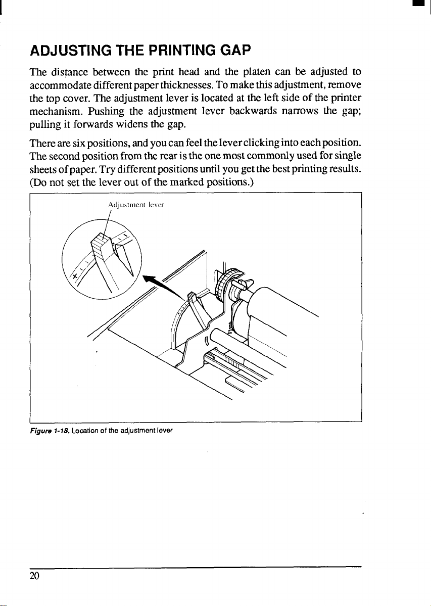
ADJUSTING THE PRINTING GAP
The dis~nce between the print head and the platen can be adjustedto
accommodatedifferentpaperthicknesses.Tomakethisadjustment,remove
thetopcover.Theadjustmentleveris locatedatthe leftsideof theprinter
mechanism.Pushing the adjustmentlever backwardsnarrows the gap;
pullingit forwardswidensthegap.
Therearesixpositions,andyoucanfeelthe Ieverclickingintoeachposition.
Thesecondpositionfromtherearistheonemostcommonlyusedforsingle
sheetsofpaper.Trydifferentpositionsuntilyougetthebestprintingresults.
(Donot settheleverout of themarkedpositions.)
Adjustment lever
Figure 1-18. Location of the adjustment lever
20
Page 30
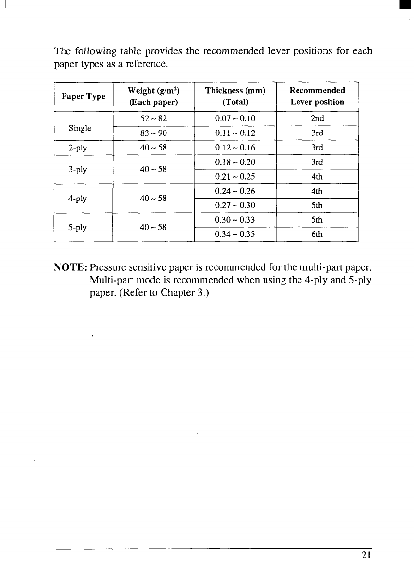
The followingtableprovidesthe recommendedlever positionsfor each
papertypesas a reference.
Paper
Single
2-ply
3-ply
4-ply
5-ply
Type
Weight (g/mz)
(Each paper) (Total)
52-82
83-90
40-58
40-58
40-58
40-58
Thickness(mm)
0.07-0.10 2nd
0.11-0.12 I 3rd
/
0.12-0.16 3rd
0.18-0.20
0.21-0.25 4th
0.24-0.26
0.27-0.30 5th
0.30-0.33 5th
0.34-0.35 6th
Recommended
Lever position
I
3rd
4th
NOTE: Pressuresensitivepaperisrecommendedforthemulti-partpaper.
Multi-partmodeis recommendedwhenusingthe 4-plyand5-ply
paper.(Referto Chapter3,)
21
Page 31

MEMO
22
Page 32

chapter2
CONTROL PANEL OPERATIONS
Thecontrolpanelbuttonscanbepressedindividuallytoperformtheoperationsindicatedbytheirnames.Otherfunctionscanbe achievedbyholding
thesebuttonsdownwhenyouturntheprinter’spoweron,orbypressingthe
controlpanelbuttonsin combination.
Thischapterexplainsallthebuttonandindicatorfunctions.
9
Pauseprinting
.
Feedpaper(fast andslow,forwardandreverse)
.
Parkfanfoldforms
.
Setthetop-of-formposition
.
Selecttheprintpitch
.
Selectafont
●
Printtestpatterns
.
Preventsoftwarefrom changingthepanelpitchandfontselections
.
Printa hexadecimaldump
●
Cleartheprinter’sbuffer
●
Changetheprintcolor(colorprinteronly)
●
Storemacrodefinition
BUTTONSAND INDICATORS
printeris equippedwithfivebuttonson thecontrolpanel.Fromleftto
The
rightthey are,(T6NT) and (FiTCR) (smallerbuttons),and ( “W4=”T),
(PAPER FEED), andC
The followingis a briefguideto the buttonsand indicatomonthe control
panel.
Figure Z-l. Control panel
ON
LINE )(larger buttons).
23
Page 33

ONLINE button
c.
ON LINE
>button setsthe printeron-lineand off-line.The status
The
changeseachtimeyoupressthe button.
Whentheprinterison-line,itcanreceiveandprintdatafromthecomputer.
Whentheprinterisoff-line,itstopsprintingandsendsthecomputerasignal
indicatingthatit cannotacceptdata.
Theprinterpowersup intheon-linestatusifpaperisloaded.If paperisnot
loaded,the printerpowersup off-linewiththe
Whenyouloadpaper,the
POWER indicatorstopsflashing,andthe printer
POWER indicatorflashing.
goeson-line.
LINE
Youwillwantto pressthe (
● Beforeand afterany otherpaneloperation
ON
button:
)
The other panel buttons operate only in the off-line state. Press the
LINE ) button to go off-line.
ON
(
operation(s),presstheC
● To pauseduringprinting
If you press the( ON
LINE
LINE
ON
)
buttonduringprinting,the printer stops
After performing the panel
buttonagainto go backon-line.
)
printingand goesoff-line,allowingyouto checktheprintoutor change
acontrolpanelsetting.Printingresumeswhenyoupressthe(
ON
LINE
buttonagaintogobackon-line.
>
● To cut fanfoldforms attheendofprinting
LINE
Whenusingfanfoldforms,youcanholdthe (
ON
buttondown
)
for one second.In additionto goingoff-line,the printeralso feedsthe
paperforwardapproximatelytwoinches.Thisallowsyoutocutitoffjust
belowthelast lineprinted.
)
Whenyoupressthe (
ON
LINE
button againto gobackon-line,the
paperfeedsbackwardstoppingwhereyouleft off.
NOTE:Thisfunctionisvalidonlywhenthebufferis empty.
PAPER FEED button
If you pressthisbuttonwhileoff-line,thepaperwillfeed forward.If you
holdthebuttondown,theprinterwillperformconsecutivelinefeeds.
24
Page 34

I
If youalsopressthe
ON
LINE
]
(
button whileyouareline-feeding,the
paperwillfeedautomaticallyto thetopof thenextpage.Thisisexplained
later.
If youpressthisbuttonwhileon-line,thiswillalternatelyflashthe
QUIET
indicatoronandoff.WheninQuietmodewiththe QUIET indicatorlit,the
printerwillprintslightlyslower,butat a reducednoiselevel.
SET/EJECT/PARK button
NOTE: Thisbuttonhasnoeffectifthe bottomfeedmodeis selected.
Pressingthis buttoncausestheprintertobeginpaperloadingifthe paperhas
notloadedwhilein the off-linestate.
If the paperhas beenloaded,thisbuttonresultsin differentfi.mctionsdependingon the positionof thereleaselever.
If the mlcaseleveris forwardforfanfoldforms,pressingthisbuttonparks
theforms.
If the releaseleverisbackforsinglesheets,pressingthisbuttonejectsthe
paper.
PITCH button
Thisbuttonallowsyoutoselecttheprintingpitch.Rememberthattheprinter
mustbeoff-linefor you to do this. Successivepressesof this buttonwill
illuminate(and select) the followingoptions in order (Note that semicondescdpitchisnotavailablein theIBMmode):
Pitch Indicator(s)
Pica(10CPI) 10
CPI
Elite(12CPI) 12CPI
CPI
Semi-condensed(15,CPI)
Condensedpica(17CPI)
Condensedelite(20CPI)
15
10CPI,COND
CPI,COND
12
Proportional PROP
Condensedproportional
PROP,COND
25
Page 35

FONT button
Thisbuttonselectsthefonttobeprinted.Draftfontisselectedatpower-up
unlessthedefaultsettingsarechanged.TochangetoHSDraft(High-Speed
Draft)oroneoftheLQ (LetterQuality)fonts,settheprinteroff-line,then
press the(-) buttonrepeatedlyuntiltheindicatorsbesidethedesired
selectionilluminate.Theselectionscycleinthefollowingorder:
Font
Draft
Roman
Sansenf
Courier
Prestige
script
option
High-SpeedDraft
Indicator(s)
HS-DRAFT,ROMAN
ROMAN
ROMAN,COURIER
COURIER
COURIER,SCRIPT
SCRIPT
OPTION
HS-DRAFT
The OptionFontselectionwillbe skippedunlessafontcartridgeisinstalled.
26
Page 36

POWER-UP FUNCTIONS
addition to their normalfunctions,all the controlpanel buttonshave
In
specialfimctionsthatoperateifyouholdthemdownwhileswitchingpower
on.
colorprinter,eachline printsinadifferentcolor.)
at,<d,i
I “#$%& ( ) I + .-. /0 I 274 st,789 : : f = > ?@’ABCDEFGHI JKLMN13FQRSTUVWXYZ[\ 1
! “#$%& I 1* +.-. i II i ? 11s I,7hCI: ; <=) ?@ABCDEFGHI JKLMNLIPQRSTUVWXYZ[\
‘ #$%& ( )
F$%d [ ) * + ,$z& I I * + .-. , III ?7d~(,
“&l ( ) *+ ,- ,
L ( ) * . ,– ,1,Ii : I J~17 b‘, : :
Figure2-3. Short self-test
●+ .-. /11I 214 5(, 7h<~ : :
?
?4.s(,7hv : : <=> ?,oABcDEf~GHIJKLMNOPQRSTUVWXYZ [ \ 1‘— abcdet’~1] I .ik 1mlIOPLII-
,., ,<(,?h,, ; <.) ?WAB(~DEFGHI JKLMNIJI>QRSTIIVWXYZ [ \ ] ‘. abrd,, f’$t) 1
<=> ?@ABCDEFGHI JKLMNOPQRSTUVWXYZ[ \ ] abrd< 1FhI Jk Inlfl,vq
7h: : <=> ?~,ABCDEFGHI JKLMNOPQRSTUVWXYZ[\ I “- abcde f: h i i k I rnn. p,l rs
.> ?w,ABCDEFGRIJKLMNOPQRSTLiVWXYZ[ \ ] --- abcdt I F11! , h I mru,k),l rs t (1
1“ abI’~~ r Ft]i i k 1mIIOP
gh , , k 1m,,,,
.1k lmllf.,PQr ~ t
Sincethe self-testoccupiesthefullwidthofthecarriage,itisrecommended
that theprinteris loaded withthewidestpaperpossibletoavoiddamageto
theprintheadand/orplaten.
27
Page 37

I
Long test mode
If the printeris turnedon while the
(PAPER FEED) buttonis pressed,the
printerwillenterthe longself-testmode.Theprinterwillprinttheversion
numberoftheprinter’sROMandthecurrentEDSsettings,followedbythe
wholecharactersetprintedineachfontandpitchavail;ble.
‘hetestcyclesendlessly,soyoumustturnthepoweroff to stopit.
c 5 old “S*]
...––..... +.––––––. –––.––-..-––.–----––-–––. .–––.–––.
D
0 , ($4”,
2s-)
–. . .
..––. .– . . . . . . . . . . . . . . . . . .
.
Fkwre 2-4. Lena self-test
.. ...
-.<,,..<,
. .
Page 38

Sincetheself-testoccupiesthefullwidlhofthecarriage,itisrecommended
thattheprinteris loadedwiththe widestpaperpossibletoavoiddamageto
the printheadand/orplaten.Inaddition,thetotalnumberoflinesprintedis
considerable,more thancan be accommodatedon a singlesheet,so fanfold
paperis recommendedforthistest.
Print area test mode
Byholdingthe(
entertheprintareatestmode.Thisway,youcanfindouthowmanylineson
yourpaper are availablefor printing.The printerwill print the first line
message,thenprintthelastlinemessageafterfeedingtothebottomofthe
page.
Ifyouhaveloadedthefanfoldpaper,onlythefirstlinemessageis printed.
,,FJA,&lc.,
) buttondownduringpower-up,the printerwill
Stay in Panel Pitch
By holdingthe(PiTCil)buttondownduringpower-up,the print pitchcan
onlybeselectedfromthecontrolpanel.Thispreventssoftwareinterference,
Youwillhear an acknowledgingbeepaspowercomeson.
Afterthe beeptone,youcanset theprinteroff-line,select a printpitch,then
returntoon-lineandstartprinting.Thepitchyouselectedwillnotbereset
or otherwisechangedby anycommandsyoursoftwaremay issue.
Stay in Panel Font
Byholdingthe (-) buttonduringpower-up,fontscanonlybe selected
fromthecontrolpanel.Thispreventssoftwareinterference.Therewillbean
acknowledgingbeepaspowercomeson,afterwhichyoucansettheprinter
off-line,selectafont,thenrctumtotheon-linestateandbeginprinting.The
sclectcdfontwillnotbechangedbyanycommandsyoursoftwaremayissue.
Stay in Panel Pitch and Font
Ifyouwanttoprotectboththepitchandfontsettingsfromsoftwarechanges,
pressboththe(~) and(~) buttonsduringpower-up.Therewillbe
two acknowledgingbeeptones.
Pressingtlmscbuttonsduringpower-updocsnotpreventyoufrommaking
anynumberof changeslaterfromthecontrolpanel.
29
Page 39

Hexadecimal dump
This feature is useful for programmerswho are debuggingprintingprograms and want to see the actual codes the printer is receiving.(Some
computemchangethecodes the programmerintended.)
Inthismode,alldatareceivedwillbeprintedinahexadecimaldumpformat,
ratherthanthecontrolcodesbeingactedon as commandcodes.
Thismodeis accessedwiththefollowingprocedure:
1. Whileholdingboth
the(PAPER FEED)and(
SEJAE~~CT
turnpowerON. A beeptonewillbe heard.
2. Beginprinting.In placeof theusualprintoutyou will get a formatted
dumpshowingexactlywhatdatatheprinterreceives.Eachlinepresents
sixteencharacters,theirhexadecimalcodestotheleftandprintablecharactersprintedon the right.
3. At the end of the hexadecimaldump,set the printeroff-line withthe
LINE
ON
(
button.Thisisnecessaryto printthelast line.
)
ThefollowingBASICprogramisasimpletestyoucanruninhexadecimal
mode:
10 LPRINT WIDTH “LPT1 : “ .255
20 FOR 1=0 TO 255
30 LPRINT CHR$(I) ;
40 NEXT I
50 LPRINT
60 END
)buttons down,
If your systempasses the codes directlyto the printer withoutchanging
them,youwill geta printoutlikeFigure2-5.
00 01 02 03 04 05 06 07
10 11 12 13 14 15 16 17
20 21 22 23 24 25 26 27
30 31 32 33 34 35 36 37
40 41 42 43 44 45 46 47
50 51 52 53 54 55 56 57
60 61 62 63 64 65 66 67
70 71 72 73 74 75 76 77
60 81 82 83 84 85 86 87
90 91 92 93 94 95 96 97
AO Al AZ A3 A4 A5 A6 A7
BO 81 R2 63 64 B5 B6 B7
CO Cl C2 C3 C4 C5 C6 C7
DO D1 D2 03 04 05 D6 D7
EO El E2 E3 E4 E5 E6 E7
FO F1 F2 F3 F4 F5 F6 F7
OD OA
Figure 2-5. Sample hexadecimal dump
08 09 OA 06 OC OD OE OF
18 19 1A 16 IC ID 1E 1F
28 29 2A 2B 2C 2D 2E 2F
38 39 3A 3B 3C 3D 3E 3F
48 49 4A 46, 4C 4D 4E 4F
58 59 5A 56 5C 50 5E SF
68 69 6A 66 6C 6D 6E 6F
78 79 7A 7B 7C 70 7E 7F
88 89 8A 8B 8C 8D 8E 8F
98 99 9A 9B 9C 90 9E 9F . . . . . . . . . .
A8 A9 AA AB AC AO AE AF
B8 B9 6A t3B BC BD 8E BF . . . . . . . . . . . .
C8 C9 CA CB CC CO CE CF . . . . . . . . . . . . .
D8 D9 DA OB DC DD DE DF . . . . . . . . . . . . . . . .
E8 E9 EA EB EC EO EE EF . . . . . . . . . . . . . .
F8 F9 FA FB FC FD FE FF . . . . . . .
. . . . . . . . . . . . . . . .
! “#$%&: i ) ~+ ; -. /
0123456789 : ; <=>?
@ABCDE FGH I JKLMNO
PQRSTUVWXYZ [\] ‘-
‘ abcdefghi jkl mno
pqrstuvwxyz ( ! ) -.
. .
.
Page 40

MostBASICS,however,arenotquitethatstraightforward.Forexample,the
IBM-PCwillgiveyoua printoutsimilarto Figure2-6.
1
00 01 02 03 04 05 06 07
OF 10 11 12 13 14 15 16
20 21 .?2 23 24 25 26 27
30 31 32 33 34 35 36 37
40 41 42 43 44 45 46 47
50 51 52 53 54 55 56 57
60 61 62 63 64 65 66 67
70 71 72 73 74 75 76 77
80 81 82 83 84 85 86 87
90 91 92 93 94 95 96 97
AO Al AZ A3 A4 A5 A6 A7
E70 B1 B2 B3 B4 B5 B6 87
CO Cl C2 C3 C4 C5 C6 C7
DO D1 02 03 D4 05 D6 07
EO El E2 E3 E4 ES E6 E7
FO F1 F2 F3 F4 F5 F6 F7
OD OA
Flgure2-& Samplehexadecimal dumpwithlBM-PC
08 09 OA 06 OC 00 OA OE
17 18 19 IB IC ID IE IF
28 29 2A 26 ZC 2D 2E 2F
38 39 3A 3B 3C 30 3E 3F
48 49 4A 46 4C 40 4E 4F
58 59 5A 56 5C 5D 5E 5F
68 69 6A 66 6C 6D 6E 6F
78 79 7A 7F3 7C 70 7E 7F
88 89 8A BB 8C 8D 8E 8F
98 99 9A 96 9C 90 9E 9F
A8 A9 AA AB AC AD AE AF
68 69 8A BB BC BD BE BF
C8 C9 CA CB CC CD CE CF
D8 D9 DA DB DC DD OE DF
E8 E9 EA EB EC ED EE EF
F8 F9 FA FB FC FD FE FF
. .. .. .
.. ... .
!“#$%&’ ()*+.-./
0123456789:;<=>?
@ABCDEFGHIJKLMNO
PQRSTUVWXYZ[\]”-
‘abcdefghijklmno
pqrstuvwxyz{j)-.
. . . . .
.. ... ... .. ...
..... . . ... ..
... .. ... ... .
... ..... ... . .
. . .. . .. .
.. ... ... .. ... ...
.. ... ... .. ... .
..
WhentheIBM-PCBASICinterpretersendshexcodeOD(carriagereturn)
it adds an extra hex OA(linefeed).Hex code 1A (end-of-file)also gets
specialtreatment:the interpreterdoes not send it at all. This can cause
problemswitigrapticsordowtioadcharacterdata.HoweveLyoucans0lve
thisproblembychangingline 30 intheprecedingprogramandaddingthe
codingshownbdow.
Codingfor IBM-PCwithmonochromedisplay:
30 GOSUB 100
100 X=INP(&H3BD)
:IF X<128 THEN 100
110 OUT &H3BC,I :OUT &H3BE,5 :OUT &H3BE,4
120 RETURN
Codingfor IBM-PCwithcoloradapter:
30 GOSUB 100
100 x=INP(&H379)
:IF X<128 THEN 100
110 OUT &H378,1 :OUT &H37A,S :OUT &H37A,4
l~o RETURN
Page 41

SWITCH COMBINATION FUNCTIONS
Several
additionalfimctionscanbe achievedbypressingthecontrolpanel
buttonsin combinations.
I
P
Fjgum 2-7. Switch combination functions of control panel
c
Buffer clear/All reset
Reverse Micro Feed I
u
Form Feed
m
Form feed
If youarcusingsinglesheets,thisoperationejects thecurrentpage.Ifyou
areusingfanfoldforms,it feedsto thetopof thenextpage.
1.
Pressthe(
Pressthe
2.
performingsuccessivelinefeeds.
Whileholdingthe
3.
button,then releaseboth buttonsat the same time. The printer will
smoothlyejectthecurrentpage.
ON LINE
(PAPER FEED> buttonandholditdown.Theprinterwillstart
buttonto settheprinteroff-line.
)
(PAPER FEED) buttondown, pressthe(
ON
LINE
)
Top of form
Whenyoupowerontheprinter,thetop-of-formpositionisautomaticallyset
tothecurrentposition.Ifthisisnotwhereyouwantthetopofthepagetobe,
youcan changethetop-of-formpositionasfollows:
LINE
1. Pressthe (
2. Movethe paper to the desired top-of-formposition by pressing the
(PAPER FEED) button,orbyperformingaforwardorreversemicro-feed.
32
ON
buttonto settheprinteroff-line.
)
Page 42

ON
ON
LINE
LINE
button.
)
)button down,presstheCPiTC17)button,
Pressandholdthe (
3.
4.
Whileholdingthe(
then releaseboth buttonsat the same time. The printer will beep to
indicatethatthetop-of-formpositionhasbeen set.
Forward micro-feed
Fortinealignment,youcanfeedthepaperforwardinverysmallincrements
follows:
as
Pressthe(
1.
Pressthe (
2.
Whileholdingthe (
3.
LINE ) buttonto set thepnntcr off-line.
ON
ON LINE
button againandholdit down.
)
]
ON LINE
buttondown,pressthe (PAPERFEED>
button.Thepaperwillstartadvancinginascnesof smallsteps.When
youwantto stop,releasebothbuttons.
Reverse micro-feed
Youcan also feedthepaperin smallincrementsin reverse,to rctum to a
higherpositiononthesamepage.
NOTE: Withfanfoldforms,donottrytorctumtoapreviouspage.Theper-
forationmay catchinsidetheprinterandcauseajam.
1. Pressthe(
2. Press’the(
3. Whileholdingthe (
ON LINE
ON LINE ) buttonagainandholdit down.
buttonto setthe printeroff-line.
)
ON LINE
)
button down,pressthe (
s,~.~~~C.T
button.Thepaperwillstartmovingbackwardsinascncsof smallsteps.
Whenyouwanttostop,releasebothbuttons.
Changing the auto loading value
Normally,the printerautomaticallyloadsthepaperoneline fromthetop
edge.
If youwantto change this value,follow thisprocedure:
1. Loadthepaperusingthe (
2. Changetheprintpositionusingthemicrofeed function.
Thelineonlhc cardholderhelpsyou to alignthebaselineofcharacters
to be printed.
3. Afteryougctthe desiredposition,pressthe[ ONLINE
thevalue.
‘;’$A’vikc’) button.
)button tosave
33
1
Page 43

I
Thisvaluewillremainunlessyoupowerofftheprinter.Ifyouwanttoretain
this value even after you turn off the power, store it using the Macro
Definitionfunction,whichisdescribedbelow.
Notethatyoucanonlychangethisvalueimmediatelyafterloadingpaper.If
youfeedpaper,youcannotchangetheautoloadingvalue.
Clearing the buffer/All reset
Theprinterstoresreceiveddata in a large memorybuffer.Thiscreatesa
problemwhenyouwanttoabandonaprintingjobandrestart:theprintermay
be holdingmore data in its buffer than it has actuallyprinted,and this
unprinteddatamustlx clearedoutbeforerestarting.Turningpoweroffisone
wayto clearthebuffer,butthereisanotherway:
Halttheprintingprogramonthecomputer.Ifprintingstopsimmediately,
1.
thebufferisclearandtherestofthisprocedureisunnecessary.Ifprinting
does not stop, continueas follows:
Pressthe(
2.
nowstop,buttheremaybedataremaininginthe buffer.
Pressandholdthe(
3.
4.
While pressing the (
_ button.Continueholdingthesetwobuttonsdown.Inone SeCOnd
youwillheara beeptonesignalingthatthebufferhasbeencleared.
If you holdthesebuttonsmoretwo seconds,you willhearthree beep
tones signalingthat the printerhas been initializedto the power-on
defaultsettings.
Releas~thesebuttons,makeanynecessarycontrolpanelsettings,thenset
5.
theprinterbackon-line.
ON LINE ) buttonto set the printeroff-line.Printingwill
LINE
ON
ON LINE
)
button.
)
button down, press and hold the
Itisessentialtohalttheprintingprogramonthecomputerbeforeyougooffline.Otherwise,whenyougobackon-linethecomputerwillstartsending
dataagainandtheprinterwillcontinueprinting,withmissingdatawherethe
bufferwascleared.
NOTE:If you are usingthe SPC-8K,Serial-ParallelConverter,resetthe
converterbypressingtheredClearbuttononitbeforeyouresetthe
printer.
34
Page 44

Selecting theprint color
Normally,the color printerprintswith black even if the color ribbonis
installed.
Withouttheaid of software,youcan changetheprintingcolorasfollows:
PresstheC
1.
2.
PresstheCFGN71buttonandholdit down.
Whileholdingthe(-) button,pressthe(
3.
ON LINE
Eachtimeyoupressthe ( =wdkr’
FONT or PITCH willblinkto showthecurrentcoloras shownbelow.
Color
Black
Magenta
cyan
Violet
4.
Releasebothbuttonsafteryouset thedesiredprintingcolor.
buttonto setthe printeroff-line.
)
S’:m+$c‘
) button,oneof the indicatorsof
Indicator Color
HS-DRAFT
ROMAN Orange
COURIER
SCRIPT
Yellow
Green
) button.
Indicator
10CPI
12CPI
15CPI
If you want to save the selectedcolorfor later use, store it usingthe
MacroDefinition.
NOTE:This functions validonlywhenthecolorribbonisinstalledintothe
colorprinter.
Store Macro Definition
You camstore the current settingsto the printer for later use with the
followingprocedure:
LINE
1.
Pressthe(
Pressthe(~) buttonandholdit down.
2.
Whileholdingthe(~>button down,press the (TiTCll>button and
3.
ON
holdthemdownuntilyouheartwo beeptones.
4.
Releasebothbuttonsat thesametimeafterthetwo beeptonesto stem
thecurrentsetting.
If youreleasethesebuttonsafterthreebeeptones,themacroiscleared.
)
button to settheprinteroff-line.
NOTE: Youcanstorethefollowingsettingswiththisprocedure.
● CurrentFont andPitch
● Currentauto-loadingamountforcut sheet
● Currentauto-loadingamountforcontinuouspaper
“Currentauto-loadingamountin ASFmode
35
Page 45

● Currentprintcolor(colorprinteronly)
DatatobestoredarecontrolledinStandardmodeandIBMmodeseparately.
For example,thedata storedin theStandardmodearenot effectivein the
IBMmode,andviceversa.
36
Page 46

chapter 3
DEFAULT SETTINGS
Most printers use abankofDIP(Dual In-linePackage)switchesinsidethe
printerto achievevariousfunctions.However,thisprintercan changethe
power-updefaultsettingsbyusingtheElectronicDIPSwitch(EDS)mode.
Thischapterexplainshowto use theEDSmode.
HOW TO SET THE EDS MODE
EDSmodehas25kindsoffunctionsyoucansetasthepower-ondefault.
The
ToentertheEDSmode,turntheprinteronwhilesimultaneouslyholdingthe
s* TF+CT
(
(PAPER FEED) and (
),
In EDSmode,theindicatorsandthebuttonsonthe controlpanelare used
as shownbelowinFigure3-1.
.
Usethe[~)button to selecttheBankNumber.OneoftheFONTindicatorswillilluminateto showtheselectedBankNumber. ~
●
Usethe (~) buttonto selecttheSwitchNumber.Oneofthe
dicatov willilluminateto showthe selectedSwitchNumber.
✎
QUIET indicatorshowsthecurrentsetting.
The
If you wantto setit ON,pressthe<
✎
Pressthe
●
Pressthe(
(PAPER FEED>button to printoutthecurrentsettings.
LINE
ON
)buttontosavethenewsettingsandtoexittheEDS
mode.
1
ON LINE
s(-~~~~<:r
)
buttons.
>button.
PITCHin-
I
Figurs 3-7. Button and indicator functions in the EDS mode
Page 47

FUNCTIONS OF THE EDS SEITINGS
Theprinteris factory-setwithallEDS switchesintheONposition.These
are the standardsettings.By changingthe settings,you can alter various
printerfunctionstomatchyourrequirements.Thefollowingquestionswill
helpyouchoosethepropersettings.
Number Function
ON OFF
A-1 Emulation STANDARD
A-2 RAMUsage
A-3 AutoLFwithCR
A-4 AutoSheetFeeder
I A-5 I GranhicsDirection
B-1
.r
Multi-part
B-2 Paper-out
B-3 Tear-off
B-4
(Reserved)
B-5 PrintableArea
c-l
PrintMode
InputBuffer DownloadBuffer
Disabled
Notfitted Fitted
I Bi-directional! Uni-directional !
Disabled
Enabled
Disabled Enabled
LeaveON
TypeA TypeB
(Seebelow)
c-2
c-3
PageLenglh
(Seebelow)
c-4
, (NotUsed)
c-5
D-1
CharacterTable
(Standardmode)
(IBMmode)
Graphics
IBM#2
D-2 IBMCodepageor
D-3 Intemationat
D-4
CharacterSet
(Seebelow)
D-5 (NotUsed)
E-1
E-2
E-3
LQFontSelection
(Seebelow)
E-4
E-5 (NotUsed)
IBM
Enabled
i
I Enabled
Disabled
--i
Italics
IBM#l
38
Page 48

Switch A-1: Do you want to use the printer in Standardmode or IBM
mode?
Selectthemodecompatiblewithyourcomputerandsoflware.In Standard
modethe printeroperatesliketheEpsonLQ-860.InIBMmodeitoperates
liketheIBMProprintcrX24E.TheONpositionselectsStandardmode.The
OFFpositionselectsIBMmode.
Switch A-2: Doesyour softwaredownloadcharacterstotheprinter?
InordertodownloadcharactersthisswitchmustbeintheOFFposition.The
printer then uses its RAM memory for storing character patterns and
providesonlyaone-lineprintbuffer.Ifyouleavethis switchON,theprinter
usesitsRAMmemoryasaninputbuffer,allowingthecomputertosenddata
fasterthanthe printerprints.
NOTE:Whcn you want to downloadcharacterswith IBM mode by the
monochromeversionprinter,youmust installthe optionalRAM
cartridge(RC-32Z).Otherwise,youcannotdownloadevenif this
switchis set OFF.
Switch A-3: Do you wantan automaticlinefeed?
If you leave this switchin the ON position,a separateline-feedcode is
requiredfrom yourcomputertoobtainalinefeed.
If you move this switchto the OFFposition,theprinterperformsboth a
carriagereturnand linefeed eachtimeit receivesa carriage-returncode.
Most computersystemssenda linefeedcode,orbothacarriagereturnand
linefeed,atthecndofeachline,so thisswitchshouldbeleft ON.
If you get double line spacingwhenyouexpect singlespacing,or if lines
overprinteachother,try changingthesettingof thisswitch.
Switch A-4: Are yougoingto usctheautomaticsheetfeeder(ASF)?
InordertousctheautomaticsheetfeederSF-1ODQ,movethisswitchtothe
OFFposition.Otherwiseleave it ON.
Switch A-5: Arc yougoingto printdotgraphicsuni-directionally?
Whenprintingindotgraphicsmode,theprintermayeithcrprintbidirection-
ally(inalternatedirections)forspccdorinonedirectiononly(unidirectional
forincreasedaccuracy).Forpracticallyallpurposes,however,bidirectional
printingissufficientlyaccurate.Inorder10print uni-directionally,movethis
switchto theOFFposition.
39
Page 49

I
SwitchB-1:Areyougoingto printonmulti-partpaper?
Youcanuseup to 3-plypaperwhenthisswitchis ON.If youwanttoprint
on4-plyor 5-plypaper,setthisswitchto theOFFposition.
Switch B-2: Doyouwantthcprintcrtosloppnntingatthecndofthc paper,
or to keepprinting?
WhenthisswitchisOFFtic printerignoresthepaper-outdetectorandprints
downto (andbeyond)thebottomedge.Otherwiseleaveit ON.
Switch B-3: Do you want to advancepaper automaticallyat the cnd of
printing?
Youcan selecttheTear Off functionwiththis switchOFF.
Whenusingfanfoldpaper,theTearOfffunctionallowsyoutotearoffonc
sheetofpaperwithoutfullyadvancingthefollowingsheet.
Switch B-4: This switch is used for technicalpurposeonly. Leave this
switchON.
Switch B-5: Whichiype of printingarea do you want to use for single
sheets?
Thisprintercanuse two typesofprintingareaformatfor singlesheets.
Byputtingthe switchON(“TypeA“),thetopofthe firstlineofprintingwill
start1/6inchf~omthetopofthepaper,andtheprinicdareawillend 1/6inch
fromtic bottomof thepaper.
ByputtingtheswitchOFF(“TypeB“),thefirstlineofprintingwillstartat
oneinchfromthetopofthepaper,andthepnntcdareawillcnd6mmfrom
thebottom of theprinter.
SwitchesC-1 and C-2: Whichprintmodedoyou wantto set?
Theseswitchesselectthedefaultprintpitchandthefontsasshownbelow.
Print Mode c-1 c-2
10CPIDRAFT
10CPIHSDRAFT
17CPIDRAFT
10CPILQ OFF RF
NOTE:If youchangetheseswitchesaflcryouhavestoredthemacro,these
settingswilloverridethemacrosetting.
40
ON ON
ON
OFF
.
OFF
Page 50

I
SwitchesC-3 and C-4: Whatis thepage lenglhof yourpaper?
LeavetheseswitchesONifyouwillbcusing1l-inchforms,Youwillneed
tochangetheswitchesifyouwillbeusingadifferentpagelengthas shown
below:
m
Switch D-1: The actionof this switchdependson the modechosenwith
switchA-1.
If you selected Standard mode, do you want italic or graphic
characters?
MovethisswitchOFFto printitalicsintheStandardcharacterset.If you
leavethis switch in the ON position,in place of italicsyou will get the
graphiccharacters,internationalcharacters,and mathematicalsymbolsof
IBMcharacterset#2. See Chapter9, charactercodes 128to 254.
IfyouselectedIBMmode,doyouwantIBMcharacterset#1or#2?
ONselectscharacterset#2, whichisforcomputerswithan 8-bitinterface
(themostcommonkind).OFFselectscharacterset#1,forcomputerswith
a 7-bitinterface.
SwitchesD-2 to D-4:Do you want an internationalcharacterset or IBM
codepage?
Internationalcharactersetsdifferintheirassignmentof14charactercodes
inthe StandardItaliccharacterset.Seethecharactertablesatthebackofthis
manual.Withtheseswitchesyoucan selectoneof eightcharactersets as
follows:
Country
U.S.A. ON ON ON
France OFF ON ON Sweden OFF ON OFF
Germany ON OFF ON
England
D-2 D-3 D-4
OFF OFF ON
Country
DenmarkI
haly
SpainI OFF OFF OFF
D-2 D-3 D-4
ON ON OFF
ON OFF OFF
41
Page 51

ExceptintheStandardItaliccharacterset,theseswitchesselectthedefault
charactercode pageasshownbelow:
IBMCode
Page D-2 D-3 D-4 IBMCode Page
#437U.S.A.
#850Multi-lingual
#860 Portuguese
#861
Icelandic
#863
ON ON ON c~adian French
OFF ON ON #865Nordic
ON OFF ON (Reserved)
OFFOFF ON (Reserved)
D-2 D-3 D-4
ON ON OFF
OFF ON OFF
ON OFF OFF
OFF OFF OFF
SwitchesE-1 to E-4:Whichfontdo youwanttoprintasthedefaultLetter
Quality?
Theseswitchesallowsyou to choosethe defaultfont selectedwhenLQ
modeis selected,as shownbelow.
I Font Name IE-1 IE-2 IE-3 IE-4 I Font Name I E-1 I E-2 I E-31 E-4 I
/ Roman
ION ION ION ION I Orator2* ION \ ONI ONIOI@
Sanserif OFF ON ON ON T’W-Light* OFF ON ON OFF
Courier ON OFF ON ON Letter-Gothic*ON OFF ON OFF
Prestige
OFF OFF ON ON Blippo*
script ON ON OFF ON H-Gothic*
I OCR-B*
OCR-A*
Orator*
IOFFION IOFFIONIOrane*
ON OFF OFF ON Cinema* ON OFF OFF OFF
OFF OFF OFF ON Code39* OFF OFF OFF OFF
OFF OFF ON OFF
ON ON OFFOFF
10FFION10FFIOF’11
Optionalfonts(markedwithanasterisk)canbe selectedonlywhenthecor-
respondingfontcartridgeis installedinthe printer.
Ifthecorrespondingfontcartridgeisnotinstalled,thenRomanisselected.
42
Page 52

I
BIDIRECTIONAL TEST/ADJUSTMENT
Thismodeis usedto adjustthealignmentof theprintheadon successive
bidirectionalpasses.Afteraperiodofsomemonths,yourprintermaywork
itselfoutof alignmentonleft and rightprintingpasses.Thiswill be most
evidentin graphicsprinting.Thismodewillprobablybeusedveryrarely.
1. Turnthe printeroff and then turn it on againwhileholdingdownthe
‘=l%wr”
(
) and (
somethinglikethe following:
*tJ DoT
LQ
2. The printer will feed the paper forwardsand backwardsduring this
operation,allowingyouto viewthepaperforoptimumalignment.
3. To adjusttheprinting,usethe(
The(
(PAPER FEED) buttonwillmovethe secondpassto theright.
SZ~AC~~CT
ON LINE
ADJUSTMENT SETTING 89 *
) buttons. The
o:
///// ///////////////////////////////////
=wkc’ )and
printer will then print
CPAPER FEED> buttons.
)button will move the second pass to the left. The
ADJUSTMENT SETTING * * *
///// ///////////////////////////////////
////////////////////// / ///////)/,,,,,,, ,
/11!! 1111/ /111111 !!!)/!1
o:
///// ///////////////////////////////////
IIlltffll!llll II
“LAVE”
(
(PAPER FEED
*** DoT
LQ o:
‘LQ -1 :
-Q
4. Whenthetwopassesarealignedwitheachothertoformone continuous
line,thebidirectionalalignmenttestis completed.
5. Tochangethemodeforwhichthebidirectionaladjustmentisperfonned,
LINE
press the (
ON
button. This will cycle between “LQ”,
)
“DRAFT” and “DRAFT COND”.
Repeatthe processfor all printmodes.
ADJUSTMENT SETTING I SS
o:
///// ///////////////////////////////////
-1 :
+1 :
(/,,,/,,,,//,,,,,,,/// /,, ,,, ,,, /,,,,,,,,
!lllllll, ,(! //1111, ,!!l[ll/, /, {/1/1 1,,1,
o:
///// ///////////////////////////////////
o:
///// ///////////////////////////////////
\\}/\J/////J//}\/ff\f\ ~}}~j~}}}}}}}}jjj}
o:
///// ///////////////////////////////////
s.JAE~ficT
(
~
ON LINE
(
(PAPER FEED
“JA’MC’
(
*X*,DOT
LQ
-Q
LQ
%RAFT
biRAFT
43
Page 53

6. Tosavethecorrectedvaluesandtoexitfromthismode,pmssthebutton.
88$ NT ADJUSTMENTsETTING ***
o:
s.$!~~cT
LQ
(
(PApER FEEDfiQ
ONLINE
(
(PApEFi FEED
sEJ!~p
(
ONLINE
(
m +, END *,*
MQ
HfRAFT
HiRAFT
-RAFT COND o z llllllllllllllllllililllllllllllllllllllllllllllllllllllllllllllllll
-1 :
///// /////////////////1111111///1///////
,, /////)///111111111//
11111 !!lll {/1 IIIIIIIIIIII{JIJIIIIIII )!)!
o:
Illlllllllllllllllllllllllllllljljjjljil
o:
///////////////////1/1/1////////////////
+1 :
JJ/}/\/\JJ////JJ//JJ//}//f~/;l//lJJJJfJf
o:
/////////////l/n///////////////////////
1,1!! 111111 !!111!1
44
Page 54

chapter 4
PRINTER CONTROL COMMANDS
Theprinterhastwoemulationmodes:StandardmodeandIBMmode.
In standardmode,theprinteremulatesthefunctionsoftheEpsonLQ-860.
In IBMmode,theprinteremulatesthe IBMPropnnter X24E.Additional
commandcodesareincludedasa supersetof theseemulations.
The emulationis changedby means of EDS switchA-1. When ON, the
printerwillbe instandardmode,andwhenOFF,theprinterwillbein IBM
mode(see Chapter3).It is notpossibleto changetheemulationmodeby
meansof softwarecontrol.
Thischapterdescribestheprinter’scontrolcommands.Somecommandsare
commontoboth thestandardandIBMmodes.Inthedescriptionsofthecommands,all commandswillbe categorizedby function.Thename of each
commandis followedby a tablelikethe onebelow:
Mode
Std.
ASCII
<ESC> “X” “1”
<ESC> “X” <1>
Mode:
Decimal Hexadecimal
27120 49 IB 78 31
27120 1 IB 78 01
Indicatesthemodeinwhichthecommandisrecognized.
Std. Standardmode(EDSswitchA-1on)
IBM IBMmode(EDSswitchA-1off)
Both BothstandardandIBMmodes
ASCII:
Indicates the ASCII coding of the command.
Controlcharactersareenclosedin pointedbrack-
ets:For example,<1>meanscharactercode 1.
Decimal:
Hexadecimal:
Givesthecommandin decimalcharactercodes.
Gives the command in hexadecimal character
codes.
Parametersforwhichvaluesmustbesuppliedareindicatedby italicletters
suchas n.
45
Page 55

FONT CONTROL COMMANDS
Select draft quality characters
Mode ASCII
Both “ “ “ “ “F” “)” “)” “9” 4040 7041 41 57 28 2846 29 29 39
Std.
((
<ESC> “X”
<ESC> “X” <O>
“O”
Decimal
27120 48
27120 0
Hexadecimal
IB 78 30
IB 78 00
Changesfromletterqualityto draftquality.Ignoredif the (FGiTf_)
buttonwaspressedduringpower-up.
Select draft pica characters
Mode ASCII
IBM
<ESC> “I” <O>
Changestodraftqualitycharacterswithpica pitch(10cpi).Ignored
if the (R5RT)or(FiT5@buttonwaspressedduringpower-up.
Decimal
27 73 0 IB 49 00
Hexadecimal
Select draft elite characters
~ModeI ASCII
Decimal
IIBM I cESC> “I” <8> 1 27 73 8
Changestodraftqualitycharacterswithelitepitch(12cpi).Ignored
if the (M>or @iRXi)buttonwaspressedduringpower-up.
Hexadecimal
I IB 49 08 I
Select draft condensed characters
1
Mode ASCII
IBM
<ESC> “I” <DLE>
Changesto draftquality characterswithcondensedpitch(17cpi).
Ignored if the CTGNT)or (FiTCFl)button was pressed during
power-up.
46
Decimal
27 73 16
Hexadecimal
IB 49 10
Page 56

Select LQ characters
Mode ASCII
std.
<ESC>
<ESC> “X”
“X” “l”
<1>
Decimal Hexadecimal
27120 49
27120 1
Changesfromdraftqualityto letterquality.TheinitialLQ fontis
Romanunlessadifferentfonthasbeenselectedbyaprecedingcommand.Ignoredif the(-> buttonwaspressedduringpower-up.
Select LQ pica characters
Mode ASCII
IBM <ESC> “I”
Changestoletterqualitycharacterswithpicapitch(10cpi).Ignored
if the- or- buttonwaspressedduringpower-up.
<2>
Decimal Hexadecimal
27 73 2
Select LQ elite characters
Mode
IBM
ASCII
<ESC>
“I” <LF>
Changesto letterqualitycharacterswithelitepitch(12cpi).Ignored
if the(T5NT)or(~~button waspressedduringpower-up.
Decimal
27 73 10 IB 49 OA
Select LQ condensed characters
IB 78 31
IB 78 01
16 49 02
Hexadecimal
Mode ASCII
IBM
<ESC> “I” <DC2>
Changestoletterqualitycharacterswithcondensedpitch(17cpi).
Ignoredifthe(TGNTjor @i7CR)buttonwaspressedduringpowerUp.
Decimal Hexadecimal
27 73 18 16 49 12
47
Page 57

I
Select LQ proportional characters
Mode
IBM <ESC> “I” d>
ASCII Decimal
Changestoletterqualitycharacterswithproportionalpitch.Ignored
if the(R5ilT)orCFi7Cil)buttonwaspressedduringpower-up.
Select LQ font
Mode
Both
std.
ASCII Decimal
<ESC>“k” n
<FS>
“C” n
Selectsan LQfontaccordingtothevalueof n. In draftmode,this
command remains dormant and takes effect later when LQ is
selected.Ignoredif thec-~ buttonwaspressedduringpowerup or thecorrespondingfontis notinstalled.
n Font
O Roman
1 Sanserif
2 Courier
3 Prestige
4 script
5 OCR-B
6 OCR-A
,7 Orator
(Option)
(Option)
(Option)
Hexadecimal
27 73 3 IB 49 03
Hexadecimal
27107 n IB 6B n
28 67 n IC 43 n
n Font
8 Orator2 (Option)
9 TW-Light
(Option)
10 LetterGothic (Option)
11 Blippo (Option)
12 H-Gothic
13 Orane
14 Cinema
15 Code39
(Option)
(Option)
(Option)
(Option)
Select font
Mode ASCII Decimal
Both
48
““ “ “ “F’ ““ “ “
((
))
Changesa fontaccordingto thevalueof n. Ignoredif the-
buttonwaspressedduringpower-up.
n Font
O Roman
1 Sanserif
2 Courier
n
40 40 70 41 41 n 28 28 46 29 29 n
n Font
3 Prestige
4 script
9 Draft
Hexadecimal
Page 58

Select italic characters
Mo’de
Std.
ASCII
<ESC>
“4”
Causessubsequentcharactemto beprintedin italics.
Select upright characters
Mode
Std. <ESC> “5”
ASCII
Stopsitalic printingandcausessubsequentcharacterstobeprinted
upright.
Emphasized printing
Mode ASCII
Both
<ESC> “E”
Causessubsequentcharactersto be emphasizedby addingextra
thicknesstoverticalstrokes.
Cancel emphasized printing
Mode Ascli
Both
<ESC> “F”
Decimal Hexadecimal
27 52
Decimal
27 53
Decimal Hexadecimal
27 69
Decimal Hexadecimal
27 70
16 34
Hexadecimal
16 35
16 45
16 46
Cancelsemphasizedprinting.
Double-strike printing
Mode
Both
ASCII
<ESC> “G”
Causessubsequentcharactersto be printedin double-strikemode
withaslightverticalpapermotioninbetween,causingathickening
of horizontalstrokes.
Forboldprint,useof double-strikeis recommendedinLQ mode,
and combined use of emphasizedand double-strike is recommendedin draftmode.
Decimal Hexadecimal
27 71
16 47
49
Page 59

Cancel double-strike printing
Mode ASCII
Both <ESC> “H”
Cancelsdouble-strikeprinting.
Start underlining
Mode ASCII
Both
<ESC> “-” “l”
<ESC> “-” <1>
Causessubsequentcharacterstobeunderlined.IBMblock graphics
characters and spaces skippedby horizontaltabulation are not
underlined.
Stop underlining
Mode
Both
ASCII
<ESC> “-” “O” 27 45 48 IB 2D 30
<ESC> “-” <O>
Stopsunderlining.
Start ovedining
Decimal Hexadecimal
27 72
Decimal Hexadecimal
27 45 49
27 45 1
Decimal Hexadecimal
27 45 0 IB 2D 00
IB 48
IB 2D 31
IB 2D 01
Mode ASCII
<p.c> “ – .. “l!!
IBM
<ESC> “ – “ <1>
Causessubsequentcharactersto be overlined.Spacesskippedby
horizontaltabulationarenot overlined.
overlining
Mode ASCII
<Esc> “ – .. ,40,.
IBM
50
<ESC> “ – “ <O>
Stopsoverlining.
Decimal Hexadecimal
27 95 49 IB 5F 31
27 95 1 IB 5F 01
Decimal
27 95 48 IB 5F 30
27 95 0 IB 5F 00
Hexadecimal
Page 60

Select score
Ivlbde
Std.
ASCII
<ESC> “ “ “-”
Start scoreaccordingto thevaluesof nl andn2,as shownbelow.
(
<1> nl n2
<O>
<3>
n] Function
1
Underlining
2
Strike-through
3 Overlining
Select ornament character
Mode
Std.
ASCII
<ESC> “q” n
Selects an ornarnent character
below.
n Character
O Normal
1 Outline
2 Shadow
3 Shadowandoutline
accordingtothevalueof n,asshown
Decimal
27 40 45 3
o 1 nl n2
Hexadecimal
IB 28 2D 03
00 01 nl n2
n2 Function
Cancel score
o
1
Single continuousline
Doublecontinuousline
2
5 Single brokenline
Doublebrokenline
6
Decimal
27113 n
Hexadecimal
IB 71 n
Superscript
Mode ASCII
Both
<ESC> “S” “O”
<ESC> “S” <O>
Causessubsequentcharacterstobeprintedassuperscripts.Doesnot
changethe characterpitch.
Decimal
27 83 48
27 83 0
Hexadecimal
IB 53 30
IB 53 00
51
Page 61

Subscript
Mode
Both
ASCII
<ESC> “S” “l”
<ESC>
“s” <1>
Decimal
27 83 49
27 83 1
Causessubsequentcharacterstobeprintedas subscripts.Doesnot
changethe characterpitch.
Cancel superscript or subscript
Mode
Both <ESC> “T”
ASCII
Decimal
27 64
Stops printing superscriptsor subscriptsand returns to normal
printing.
CHARACTER SET COMMANDS
Select standard character set
Mode ASCII
Both
<ESC> “t” “O”
<ESC>
Std.
<FS>4“I” “O”
<FS>
“t” <o>
“I” <O> 28 73 0
Decimal
27116 48
27116 0
28 73 48
Hexadecimal
IB 53 31
IB 53 01
Hexadecimal
IB 54
Hexadecimal
IB 74 30
IB 74 00
IC 49 30
Ic 49 00
Selectsthe standardcharacterset.This is the power-updefaultin
StandardmodeifEDSswitchD-1 is OFF.
Select IBM character set
Mode
BottI
Std.
52
ASCII
<ESC>“t” “l”
<ESC>
“t” <1> 27116 1
<FS> “I” “l”
<FS>
“I” <1> 28 73 1
Selectsan IBMcharacterset.Thisis thepower-updefaultinIBM
mode.
Decimal
2711649
28 73 49
Hexadecimal
IB 74 31
IB 74 01
Ic 49 31
IC 49 01
Page 62

Select character set #1
Mode ASCII
Both <ESC> “7”
Selects character set Ml.
Decimal
27 55 IB 37
Hexadecimal
Select character set #2
Mode ASCII
Both <ESC> “6”
Selectscharacterset#2.
Decimal Hexadecimal
27 .54 IB 36
Select international character set
Mode ASCII Decimal Hexadecimal
Std. <ESC>“R” n
Selects an international character
accordingtothevalueof n.
n Characterset n Characterset
O U.S.A
1 France
2 Germany
3 England
4 DenmarkI
5 Sweden
6 Italy
7 SpainI
27 82 n IB 52 n
setin the Standardcharacterset
8
Japan
Norway
9
10
DenmarkII
11
SpainII
12
LatinAmerica
13
Korea
14
Irish
Legal
64
Thefirst eight of thesecharactersets(fromU.S.A.to SpainI) can
be selectedaspower-updefaultsby EDS switchesD-2to D-4.
Page 63

Select IBM code page
Mode ASCII Decimal Hexadecimal
Both
<ESC> “ “ “T” <4> <O> 27 91 84 4 0
[
<0> <0> nl n2
o
0 nl d
IB 5B 54 04 00
00 00 nl d
Changesthecodepageofthe currentIBMcharactersetaccording
to thevaluesof nl andn2.
nl n2 Codepage
1
181
3 82
3 92
3 93
3 95
3
97
#437U.S.A.
#850Multi-lingual
#860Portuguese
#861Icelandic
#863CanadianFrench
#865Nordic
These codepages can be selectedas power-updefaultsby EDS
switchesD-2to D-4.
Enable printing of all character codes
Mode ASCII
IBM <ESC> ‘Y”
d d 27 92 d d IB 5C nl n2
Decimal Hexadecimal
EnablesprintingofallcharactersintheIBMcharacterset,including
thoseassignedto charactercodeswhich are normallyconsidered
controlcodes.Thiscommandremainsineffectforthenextrd +n2
x256 characters,wherenl andn2arenumbersbetweenOand255.
Duringthisintervalnocontrolfunctionsareexecuted.Ifacodewith
no assignedcharacteris received,theprinterprintsa space.
Enable printing of all character codes on next
character
Mode
IBM <ESC> “ “ “
ASCII
This commandoperateslike <ESC>‘1”exceptthat it remainsin
effectfor onlyonecharacter.
54
Decimal Hexadecimal
27 94
IB 5E
Page 64

Select slash zero
Mode ASCII
Std.
<ESC> “ - “
<ESC> “ - “
“l”
<1>
Decimal
27126 49
27126 1
Hexadecimal
IB 7E 31
IB 7E 01
Causessubsequentzerocharactersto be overprintedwith a slash
(0).
Select normal zero
Mode
std.
ASCII
<ESC>“- “ “O”
<ESC> “ - “
<O>
Decimal
27126 48
27126 0
Causes subsequentzero characters to be printed normally (0),
withouta slash.
Hexadecimal
IB 7E 30
IB 7E 00
CHARACTER SIZE AND PITCH COMMANDS
Pica pitch
Mode ASCII
Std. <ESC> “P”
IBM
2DC2>
Decimal
27 80
18
Hexadecimal
IB 50
12
In Standardmode,changesfromeithereliteor semi-condensedto
picapitch (10 cpi)or fromcondensedeliteto condensedpica(17
cpi).In IBMmode,changesfromeithereliteor condensedtopica
Cpi).Ignored iftheCPiTCR)buttonwaspressedduringpower-up.
(10
Elite pitch
Mode ASCII
Std. <ESC> “M”
IBM <ESC> “:”
Changesfromeitherpicaor semi-condensedto elitepitch(12cpi)
or fromcondensedpicato condensedelite(20cpi).Ignoredif the
_ buttonwaspressedduringpower-up.
Decimal
27 77
27 58
Hexadecimal
IB 4D
IB 3A
55
Page 65

Semi-condensed pitch
Mode ASCII
<ESC> “g”
Std.
Changesfromeitherpica or eliteto semi-condensedpitch(15cpi).
Ignoredif the(FTiTiTlbuttonwaspressedduringpower-up.
Condensed printing
Mode
Both
ASCII
<Sb
<ESC> <Sb
Changesfrom pica to condensedpica (17 cpi) or from elite to
condensedelite(20cpi).Ignoredifthe(FiT5R)buttonwaspressed
duringpower-up.
Cancel condensed printing
Mode ASCII
Both
<DC2>
In Standardmode,changesfromcondensedpicato normalpicaor
fromcondensedelitetonormalelite.InIBMmode,alwayschanges
to normalpica. Ignoredif the(FRCi7)buttonwas pressedduring
power-up.
Decimal
27103 IB 67
Decimal Hexadecimal
15
27 15 IB OF
Decimal
18 12
Hexadecimal
OF
Hexadecimal
Expanded printing
Mode
Both
ASCII
<ESC> “W” “l”
<ESC> “W” <1>
Causessubsequentcharacterstobe expandedto doublewidth.
Cancel expanded printing
Mode ASCII
Both
56
<ESC> “W” “O”
<ESC> “W” <O>
Stopsexpandedprintingandreturnstonormalwidth.
Decimal Hexadecimal
27 87 49
27 87 1
Decimal Hexadecimal
27 87 48
27 87 0
IB 57 31
IB 57 01
IB 57 30
IB 57 00
Page 66

Expanded printing for one line
hhde ASCII
<so> 14 OE
-
Both
<ESC> <SO>
Decimal
27 14
Causessubsequentcharactersinthecurrentlineto beexpandedto
doublewidth.Charactersreturntonormalwidthafterthenextline
feed(<LF>).The<DC4>,<VT>,<FF>,and<ESC>“W”Ocommandsalsocancelexpandedprinting.
Cancel one-line expanded printing
Mode ASCII
Both
<DC4>
Stopsone-lineexpandedprintingsetwith<S0> or <ESC><S0>.
Doesnotcancel<ESC>“W” 1.
Decimal
20 14
Select character width
Mode
Std. <FS> “E” n
ASCII
Decimal Hexadecimal
28 69 n
Selectacharacterwidthaccordingtothevalueofnasshownbelow.
n
Characterwidth
Normal-wide
o
1
Double-wide
2
Triple-wide
Hexadecimal
IB OE
Hexadecimal
IC 45 n
Select proportional spacing
Mode
Std.
IBM
ASCII
<ESC> “p” “l”
<ESC> “p” <1>
<ESC> “P” <1>
Causessubsequentcharacterstobeproportionallyspaced.Ignored
if the(~’ buttonwaspressedduringpower-up,
Decimal
27112 49
27112 1
27 80 1
Hexadecimal
IB 70 31
IB 70 01
IB 50 01
57
Page 67

Select fixed spacing
Mode ‘ASCII
Std.
IBM <ESC>
<ESC> “p” “O”
<ESC>
“p” <o>
“P” <o>
Causessubsequentcharactersto be printed with fixed character
spacing.Ignoredifthe(PiTCillbuttonwaspressedduringpower-up.
Select master print mode
Mode
Std.
ASCII
<ESC> “!” n
Selectsa combinedprint mode accordingto the value of n. The
valueofnisthesumofthevaluesgivenbelowforthedesiredcharacteristics.
Examples:n= 1gives elite;n=9(1 + 8)givesemphasizedelite;n
= 137(1+ 8 + 128)givesunderlinedemphasizedelite.
Function n value
Underline
Italic 64
Expanded
Doublestrike
Emphasized
Condensed[*] 4
Proportional[*] 2
Elite [*]
Decimal
27112 48
27112 0
27 80 0 IB 50 00
Decimal
27 33
n IB 21 n
Hexadecimal
IB 70 30
IB 70 00
Hexadecimal
128
32
16
8
1
[*IIgnoredifthe(~) buttonwaspressedduringpower-up.
Increase character spacing
Mode
Std.
58
ASCII
<ESC> <SP>
n
Increasesthe space betweencharactersby n dots, where n is a
numberfromOto 127.Usedinmicrojustification.
Decimal Hexadecimal
27 32 n
IB 20 n
Page 68

Select double or quadruple size
Mode ASCII Decimal Hexadecimal
Std. <ESC> “h” n 27104 n IB 68 n
Selectsthesizeof subsequentcharactemas shownbelow.Extrahighcharactersalignalongthecap-lineofnormalcharacters,with
the baselinetemporarilymovingdown.Linespacingistemporarily
doubledwhenn = 1 andquadrupledwhenn =2.
n Effect
O Normalsize
1 Double-high,double-wide
2 Quadruple-high,quadruple-wide
Select character size
Mode
Both
ASCII Decimal Hexadecimal
“ “ “ “ “S” “ “ “ “ n
((
))
40 40 83 41 41 n
Selectsacombinationofcharacterheightandwidthaccordingtothe
valueof n, as below.Doesnotmovethebaseline.
n Characterwidth
O Singlewidth
1 Doublewidth
2 Singlewidth
3 Doublewidth
Print double-height characters
Mode ASCII
<ESC>
Std.
<ESC>
<FS>
<FS>
Printssubsequentcharactersat doubleheightwithoutmovingthe
baseline,andwithoutchangingthelinespacing.
“W” “l”
“W” <1>
“v” “l” 28 86 49 IC 56 31
“v” <1> 28 86 1 IC 56 01
Decimal
27119 49 IB 77 31
27119 1 IB 77 01
28 28 53 29 29 n
Characterheight
Singleheight
Singleheight
Doubleheight
Doubleheight
Hexadecimal
59
Page 69

Return to normal height
Mode
Std.
ASCII
<ESC>
<ESC>
<FS>
<FS> “v” <o>
“W” “O”
“W” <O>
“v” “0”
Decimal Hexadecimal
27119 48
27119 0
28 86 48 IC 56 30
28 86 0 IC 56 00
IB 77 30
IB 77 00
Terminatesdouble-heightprintingandprintssubsequentcharacters
atnormalheight.
Select character height, width, and line spacing
Mode
IBM
ASCII
<ESC> “[” “@” <4> <o>
<0> <0> n m
Selectsa combinationof characterheight,width,andline spacing
accordingtothevalueofnandm,asbelow.Docsnotmovethebase
line,
Linespacing Characterheight
n
o Unchanged
1
Unchanged
2 Unchanged
16 ‘Single
17 “Single
18 Single
32 Double
33 Double
34” Double
Decimal Hexadecimal
27 91 64 4 0
OOnm 00 00 n m
IB 5B 40 (!4 00
Unchanged
Singleheight
Double height
Unchanged
Singleheight
Doubleheight
Unchanged
Singleheight
Doubleheight
60
m
Characterwidth
1 Singlewidth(sameas <ESC>“W” O)
Doublewidth(sameas<ESC>“W” 1)
2
Page 70

VERTICAL POSITION COMMANDS
Set line spacing to 1/8inch
IModeI
Both <ESC> “O”
ASCII Decimal
1 I
27 48
Setsthedistancethepaperadvancesor reversesin subsequentline
feedsto 1/8inch.
Set line spacing to 7/60 or 7/72 inch
Mode
Both <ESC> “l” 27 49
ASCII Decimal
Setsthedistancethepaperadvancesor reversesin subsequentline
feedsto 7/60inch (standardmode)or7/72inch(IBMmode).
Set line spacing to 1/6inch
[ModeI ASCII
,
Std.
<ESC> “2” 27 50
Setsthedistancethepaperadvancesorreversesin subsequentline
feedsto 1/6inch.
Decimal Hexadecimal
Set line spacing to n/360 inch
Mode ASCII
Std.
cESC> “+” n 27 43 n
<FS> “3” n 28 51
! Decimal
n
Hexadecimal
1
IB 30
Hexadecimal
IB 31
IB 32
Hexadecimal
IB 2B n
IC
33 n
Setsthedistancethepaperadvancesor reversesin subsequentline
feedsto n/360
inch, where n is between Oand255.
61
Page 71

Set base unit for line spacing
Mode ASCII
IBM
<ESC> “ “ ‘1”
[
<O> <O> <O>
<4>
<o> 27 91 92 4 0 IB 5B 5C 04 00
n
Decimal Hexadecimal
OOn 00 00 00 n
o
Setsthebaseunit forthelinespacingcommands,<ESC>“3”and
cESC>“J”.Ifthevalueof n is 180,thebaseunitissetto 1/180”.If
the value of n is 216, the base unit is set to 1/216”.If otherwise
specified,thiscommandisignored.Thiscommandbecomeseffectiveonly after<ESC>“3” or <ESC>“J”is received,The default
baseunitis set to 1/216”.
Set line spacing to nl180 inch or n/216 inch
Mode ASCII
Both
<ESC>
Sets the distance the paper advances or reverses in subsequent line
feeds torz/180
n=0,in Standardmodethe line-feeddistanceissettoO,butinIBM
modethiscommandis ignored.
“3” n
inchorn/216inch,wherenis betweenOand255.If
Decimal Hexadecimal
IB
27 51 n
33 n
Set line spacing to n/60 inch or n/72 inch
Mode
Both <ESC> “A” n
ASC114 Decimal
27 65 n
Hexadecimal
IB 41 n
62
In Standardmode,setsthedistancethepaperadvancesor reverses
insubsequentlinefeedston/60inch,wherenisbetweenOand255.
If n =0,thelinespacingis setto O.
In IBM mode, this commanddefinesthe distancethe paper advancesor reversesinsubsequentlinefeedston/72inch,wherenis
between1and85.Thenewlinespacingdoesnottakeeffectuntilthe
next<ESb “2”command.
Page 72

Execute <ESC> “A”
Mode ASCII
IBM
<ESC>
Sets the line spacingto the value defined by the last preceding
“2”
<ESC>“A” command.Setsthelinespacingto 1/6inchif thereis
no preceding<ESC>“A” command.
Line
Mode ASCII
feed
Both <LF>
Prints the current line
precedingcommandsforthelinespacing.
Reverse line feed
Mode ASCII
Std. <ESC> cLF>
IBM
<ESC>““
1
Printsthecurrentlineandfeedsthepaperinthereversedirectionto
the preceding line. See the preceding commands for the line
spacing.Ignoredwhenfrictionfeedisused.
Decimal
27 50
Decimal
10
Hexadecimal
IB 32
Hexadecimal
OA
andfeedsthepaperto the nextline.Seethe
Decimal
27 10
27 93
Hexadecimal
IB OA
IB 5D
Select forward feed mode
Mode ASCII
Std. <FS>
“F’
Cancelsthereversefeedmodeandselectsforwardfeedmode.This
is thedefaultsettingatpower-on.
Select reverse feed mode
Mode ASCII
Std. <FS>
Selectsreversefeed mode. Reversesthe directionof all vertical
movements.Ignoredwhen frictionfeedor bottom feed is used.
“R”
Decimal
28 70
Decimal
28 82
Hexadecimal
IC 46
Hexadecimal
IC 52
Page 73

Perform one n/180-inch orn/216-inch line feed
IMode\
ASCII
IBoth I <ESC> “J” n
Decimal Hexadecimal
27 74 n I IB 4A n I
I
Feedsthe paperonceby rz/180inchesor n/216inches,where n is
between1and255.Doesnotmovetheprintpositionrightorleftin
thestandardmode.Doesnotchangethe line-spacingsetting.
Perform one n/180-inch reverse line feed
Mode ASCII
Std. <ESC> “j” n
Feedsthepaperoncebyn/180inchesinthereversedirection,where
nisbetween1and255.Doesnotmovetheprintpositionrightorleft.
Doesnotchangetheline-spacingsetting.
Decimal Hexadecimal
27 106 n IB 6A n
Feed paper n lines
IModel ASCII I Decimal
Std.
<ESC> “f’ “1” n
<ESC>
“f’ <1> n 27102 1 n IB 66 01 n
27102 49 n IB 66 31 n .
Feedsthe papern linesfromthecurrentline,wherenis betweenO
and 127.
I Hexadecimal I
Set top of page at current position
Model ASCII I Decimal I Hexadecimal
IBM I <ESC> “4”
I 27 52 I IB 34
Setsthecurrentpositionasthetop-of-pageposition.Notethatthis
canalsobe donefromthecontrolpanel.
Set page length ton lines
ModeI ASCII I Decimal I Hexadecimal I
Both I <ESC> “C” n I
Setsthepagelengthto n linesin thecurrentlinespacing,wheren
isbetween1and 127inStandardmodeorbetween1and64inIBM
mode.Changingthe line spacinglater doesnot alterthe physical
pagelength.Thecurrentlinebecomesthetopof thepage.
64
27 67 n / IB 43 n I
Page 74

Set page length to ~ inches
Mode
Both
ASCII
<ESC> “C” <0> n
Setsthepagelengthto n inches,wheren is between1 and 32 in
Standardmode orbetween1and64in IBM mode.The currentline
becomesthetopof the page.
Set bottom margin
Mode
Both
ASCII
<ESC> “N” n—
Setsthebottommarginton lines,wherenisbetween1and 127in
Standardmode or between 1 and255in IBMmode. The bottom
marginis resetwhenyouchangethepagelength.
Cancel bottom margin
Mode
Both
ASCII
<ESC> “O”
Cancelsthebottommargin.
Form feed
Decimal Hexadecimal
27 67 0 n
Decimal Hexadecimal
27 78 n
Decimal
27 79
IB 43 00 n
IB 4E n
Hexadecimal
IB 4F
Mode
Both
ASCII
<FF>
Feeds the paper to the top of the next page according to the current
page length, and moves the print position to the left margin. When
the automatic sheet feeder (ASF) is selected (EDS switch A-4 is
OFF), this command ejects the current page.
Decimal Hexadecimal
12 Oc
65
Page 75

Return to top of current page
IModeI
I Std. I <ESC> <FF>
ASCII Decimal Hexadecimal
I 27 12 I
IB OC
Feedsthe paperbackwardto the top of the currentpage.Ignored
whenfrictionfeedis used.
Disable paper-out detector
Mode ASCII Decimal Hexadecimal
Both <ESC> “8”
27 56 IB 38
Causesthe printerto disregardthe signalsent by the paper-out
detector,enablingprintingtothebottomofthepaper.Overridesthe
settingof EDS switchB-2.
Enable paper-out detector
Mode ASCII Decimal Hexadecimal
Both <ESC> “9”
27 57
IB 39
Causesthe printerto stop printingbefore the end of the paper.
OverridesthesettingofEDS switchB-2.
Set vertical tab stops
I
Mode ASCII
Both
<ESC> “B” nl n2 <O>
Cancelsallcurrentverticaltabstopsandsetsnewverticaltabstops
atlinesnl, n2,etc.,wheren], n2,etc.arenumbersbetween1and
255.Amaximumof 16verticaltabstopscanbe set.Thetab stops
mustbe specifiedin ascendingorder;anyviolationof ascending
orderterminatesthetabstoplist,”StandardterminationisbythecO>
controlcode.Theverticaltabstopsaresetintermsofthecurrentline
spacinganddo notmoveif theline spacingis changedlater.
66
Decimal Hexadecimal
2766 nl n2 .. 0
IB 42
nl n2 ... 00
Page 76

Set vertical tab stops every n lines
Mode
Std.
ASCII
<ESC> “e” “l” n
<1> n
<ESC>
“e”
Decimal Hexadecimal
27101 49 n
27101 1 n
Cancelsall currentverticaltabstopsandsetsnewtabstopseveryn
lines,wheren is between2 and 127.
Set vertical tab stops in channel
Mode ASCII
Std.
<ESC> “b”
Cancelsallcurrentverticaltab stopsin channelnO,(whereM is
betweenOand7)andsetsnewverticaltabstopsinthischannel.(A
charnel is a set of verticaltab stops selectedby the cESC> “~’
command.)See<ESC>“B” forparametersnl, n2, ...<0>.
nO d
d ...
<o> n2 ... 0
Decimal
27 98 nO nl
Select vertical tab channel
Mode ASCII
Std. <ESC>
Selectsa setof verticaltab stopsdesignatedbya channelnumber
(nO)fromOto7.Thetabstopsineachchannelaresetby<ESC>’’b”.
“r’ nO
Decimal
27 47 nO IB 2F no
IB 65 31 n
IB 65 01 n
Hexadecimal
16 62 no n]
d ...
Hexadecimal
00
Vertical tab
Mode ASCII
Both <VT>
Feedsthepaperto the next verticaltab stop andmovesthe print
positiontotheleft margin.Performsaline feedifnoverticaltabsare
set,asatpower-up.Feedstothetopofthenextpageifverticaltabs
are setbutthe currentlineis at orbelowthelastverticaltab stop.
Decimal
11
Hexadecimal
OB
Page 77

HORIZONTAL POSITION COMMANDS
Set left margin
Mode ASCII Decimal
Std.
<ESC> “l” n
27 108 n IB 6C n
Setstheleftmarginatcolumnn (wherenis betweenOand255)in
the current characterpitch (pica pitch if proportionalspacingis
selected).The left margindoesnot moveif the characterpitch is
changedlater.Theleftmarginmustbeatleasttwo columnsto the
leftoftherightmarginandwithinthelimitsbelow:
Pica
Elite
Semi-condensed
Condensed pica
Condensed elite
Expanded pica
Expanded elite
Expanded semi-condensed
Expanded condensed pica
Expanded condensed elite
Set right margin
Mode ASCII ‘ Decimal
Std.
<ESC>
“0” n
27 81 n IB 51 n
Setstherightmarginatcolumnninthecurrentcharacterpitch(pica
pitch if proportionalspacing is currently selected). Column n
becomesthelastcharacterpositioninthelinc.Thenghtmargindoes
notmove if the characterpitchis changedlater.The rightmargin
mustbe withinthelimitsbelow:
Pica
Elite
Semi-condensed
Condensed pica
Condensed elite
Expanded pica
Expanded elite
Expanded semi-condensed
Expanded condensed pica
Expanded condensed elite 4<
Hexadecimal
Hexadecimal
4 s n s so
5 s ~ ~ 9(j
G s n g 12,()
7 ~ n <137
s s n ~ l(jo
2< ~ <40
3 s n s 48
3 s n s GO
4< n ~ (jS
n S 80
68
Page 78

Set left and right margins
Mode ASCII Decimal Hexadecimal
IBM
<ESC>
Sets theleftmarginatcolumnnZandtherightmarginatcolumnn2.
“X”
nI n2 27 88 nl n2
IB 58 nl n2
See the precedingcommandsfor margin restrictionsand other
notes.
Carriage return
IModel ASCII
IBoth I <CR>
I Decimal
I Hexadecimal I
I 13 I OD
Printsthecurrentlineandreturnsthenextprintpositionto theleft
margin.IfEDSswitchA-3is OFF,alsoperformsa line feed.
Set automatic line feed
Mode ASCII Decimal Hexadecimal
LBM
<ESC>“5” <1>
27 53 1 IB 35 01
Causesthe printerto performboth a carriagereturnandline feed
eachtimeit receivesa <CR>code.This commandtakespriority
overEDS switchA-3.
Cancel automatic line feed
Mode ASCII
IBM
<ESC> “5” <O>
Causestheprintertoperformonlyacarnagereturnwhenitreceives
a <CR>code.ThiscommandtakespriorityoverEDS switchA-3.
Decimal Hexadecimal
27 53 0 IB 35 00
Backspace
I
Mode ASCII
Both as>
Movestheprint position one column to the left. Ignored if the print
position is at the left margin. This command can be used to
overstrike or combine characters.
Decimal Hexadecimal
8 08
69
Page 79

Leftjustify
Mode ASCII
Std.
<ESC> “a” “O”
<ESC>
Alignssubsequenttextwiththeleftmargin,leavingtherightmargin
ragged.
Center text
Mode ASCII
<ESC> “a” “l”
Std.
<ESC> “a”
Centerssubsequenttextbetweentheleft andrightmargins.
Rightjustify
Mode I ASCII
<ESC> “a”
Std.
<ESC>
Alignssubsequenttextwiththerightmargin,leavingtheleftmargin
ragged.
Fulljustify
Decimal
27 97 48 IB 61 30
“a” <O> 27 97 0
Decimal
27 97
<1>
“2”
“a” <2> 27 97 2
27 97 1 IB 61 01
I Decimal
27 97 50
Hexadecimal
IB 61 00
Hexadecimal
49 IB 61 31
I Hexadecimal
IB 61 32
IB 61 02
Mode ASCII
Std.
<ESC> “a” “3”
<ESC> “a” <3>
Alignssubsequenttextbetweenthe left andrightmargins.
70
Decimal Hexadecimal
27 97 51
27 97 3 IB 61 03
IB 61 33
Page 80

Set horizontal tab stops
Mode ASCII
Both
<ESC> “D”
Decimal
d ...
nl
<0> 27 68 nl n2 ... 0
Hexadecimal
IB 44 nl n2 ... 00
Cancelsallcurrenthorizontaltab stopsandsetsnew tab stopsat
columnsnl, n2,etc.inthecurrentcharacterpitch(picapitchifproportional spacing is currently selected),where nl, n2, etc. are
numbersbetween1 and255.Themaximumnumberof horizontal
tabstopsallowedis32in Standardmode and64in IBMmode.The
tab stops must be specifiedin ascendingordec any violationof
ascendingorderterminatesthetabstoplist.Standardterminationis
bythecO>controlcode.To clearalltabstops,specify<ESC>“D”
<o>.
Set horizontal tab stops every n columns
Mode
Std.
ASCII
<ESC> “e” “O”
<ESC> “e” <O> n
n
Decimal
27
101 48 n
27101 0 n
Cancelsallcurrenthorizontaltabstopsandsetsnewtabstopsevery
n columns,wheren is between1and 127.
Hexadecimal
IB 65 30
IB 65 00 n
Reset,all tab stops
Mode
IBM <ESC> “R”
ASCII
Decimal
27 82
Hexadecimal
IB 52
n
Resetsthehorizontaltabstopsto theirpower-upvaluesinwhicha
tab stopis setevery8 columnstartingatcolumn9.Alsoclearsall
verticaltab stops.
Horizontal tab
Mode ASCII
Both <HT>
Movestheprintpositionto thenexthorizontaltabstop.Ignoredif
thereisnonexthorizontaltabstopinthecurrentline.Notethatwhen
underliningis selected,spacesskippedby horizontaltabulationare
notunderlined.
Decimal
9
Hexadecimal
09
Page 81

Relative horizontal tab
Mode ASCII
Std. <ESC> ‘Y” nl &!
Decimal
27 92 nl n2
Movestheprintpositionrightorleftaspecifieddistance(maximum
8inches).Ignorediftheresultingpositionisbeyondthe rightorleft
margin.Theformulasforthedistanceanddirectionareasfollows:
If n2isbetweenOand63,theprintheadmovesrightby (nl + n2x
256)dots.
Ifyouwanttomovetheprintheadtotheleft,nl andn2areobtained
by subtractingthevaluefrom65536,anddividingthe resultinto
highandlowbytes.
Relative horizontal tab in inches
Mode ASCII
IBM
<ESC>
Setsthe nextprintpositionto (nl +n2x 256)/120inchesfromthe
currentposition.
Ignoredif thispositionis beyondtherightmargin.Themaximum
positionis 8 inches.
“d” nl n2
Decimal Hexadecimal
27100
td n2
Absolute ,horizontaltab in inches
Hexadecimal
1B 5C nl n2
IB 64 nl n2
Mode ASCII
Std. <ESC> “$” nl n2
Setsthenext printpositionto(nl +n2x256)/60inchesfromthelefi
Decimal Hexadecimal
27 36 nl n2 IB 24 d n2
marginon the currentline.Ignoredif this positionis beyondthe
rightmargin.The maximumpositionis 8 inches.
Absolute horizontal tab in columns
/Mode I ASCII
<ESC> “f’ “O”
Std.
<ESC>
Movesthe next print positionto column n fromthe left margin,
wheren is betweenOand 127.
72
n
“f’ <O> n
Decimal Hexadecimal
27 102 48 n
27 102 0 n
I
IB 66 30 n
IB 66 00 n
Page 82

I
GRAPHICS COMMANDS
Print normal-density 8-bit graphics
[Mode/ ASCII Decimal
Both
<ESC> “K” nl n2
ml d ...
27 75 nI d
ml m2 ... ml d ...
Hexadecimal
IB 4B
nl n2
Prints bit-imagegraphicsat 60 dots per inch horizontally.The
graphicimageis8dotshighandnl +n2x 256dotswide.Maximum
widthis 8 inches(480dots).ml, m2, ... arethe dotdata,eacha 1-
byte valuefromOto255representing8verticaldots,withthe most
significantbitat thetop andtheleastsignificantbitat thebottom.
Thenumberof databytesmustbenl + n2 x 256.Dotsbeyondthe
rightmarginareignored.Attheendofbit-imageprintingtheprinter
returnsautomaticallyto charactermode.
Print double-density 8-bit graphics
Mode ASCII Decimal
Both
<ESC> “L”
nl d 27 76 nl d IB 4C nl n2
ml m2 ... ml d .. .
Printsbit-imagegraphicsat 120dotsperinchhorizontally(maximum960dotswide).See<ESC>“K”forotherinformation.
Hexadecimal
ml m2 ...
Print double-density, double-speed 8-bit graphics
Mode ASCII
Both
<ESC> “Y” nl n2
ml m2 ...
Decimal Hexadecimal
27 89 nl d
ml m2 .. ml m2
IB 59 nl n2
Printsbit-imagegraphicsat 120dotsperinchhorizontally(maximum960dots wide),skippingeveryseconddotin the horizontal
direction.See<ESC>“K”for otherinformation.
Print quadruple-density 8-bit graphics
Mode ASCII
Both
<ESC> “Z” nl n2
Printsbit-imagegraphicsat240dotsper inchhorizontally(maximum 1920dotswide),skippingeveryseconddotin thehorizontal
direction.See<ESC>“K” for otherinformation.
ml d ...
Decimal Hexadecimal
27 90 nl d IB 5A nl n2
ml d ...
ml m2 ...
73
Page 83

Print hex-density 24-bit graphics
Mode ‘ASCII
<FS>
“Z”
Std.
ml d m3 ..
nl d
Prints 24-bitdot graphicsat 360 dots per inch horizontally.The
graphics image is 24 dots high and n] + n2 x 256 dots wide.
Maximumwidthis8 inches(2880dots).Inthedataml, m2,m3...
eachthreebytesrepresent24verticaldots.In theleftmostposition,
themostsignificantbitofml isthetopdot;theleastsignificantbit
ofm1is theeighthdotfromthetop;themost significantbitofm2
is the ninthdot;theleast significantbit of m2 is the sixteenthdot
fromthetop;themostsignificantbitofm3is the seventeenthdot
fromthetop;theleastsignificantbitofm3isthebottomdot.Therest
ofdatais similar.Thenumberofdatabytesmustbe3 x (nl + n2x
256).Dotsbeyondthe rightmarginareignored.Atthe endofdot
graphicsprinting, the printer returns automaticallyto character
mode.
Select graphics mode
Mode ASCII
<ESC> “*” nO nl
Std.
74
&
ml ml ...
Selectsone of elevengraphicsmodesdependingonthevalueofnO
andprintsbit-imagegraphicsinthismode.See<ESC>“K” (for8bitgraphics)or<FS>“Z” (for24-bitgraphics)forinformationon
n], n2,ml, m2,...
nO Graphicsmode
O 8-bitNormal-density
1
8-bitDouble-density
2 8-bitDouble-density,double-speed
3 8-bitQuadruple-density
4 8-bitCRTgraphics,modeI
6 8-bitCRTgraphics,modeII
32 24-bitNormal-density
33 24-bitDouble-density
38 24-bitCRTgraphics
39 24-bitTriple-density
40 24-bitHex-density
Decimal Hexadecimal
28 90 nl nl
ml d d ...
Decimal Hexadecimal
27 42 nO nl IB 2A nO nl
n2 ml d ...
1C 5A n] n2
ml ml m3 ...
n2 ml d ...
(60 dotsper inch)
(120dotsper inch)
(120dotsper inch)
(240dotsper inch)
(80 dotsper inch)
(90 dotsper inch)
(60 dotsper inch)
(120dotsper inch)
(90 dotsper inch)
(180dotsper inch)
(360dotsper inch)
Page 84

I
Select graphics mode
/Mode/
IBM
ASCII Decimal
<ESC> “ “ “g” nl n2
[
ml d ...
mO
Selectsoneof eight graphicsmodes dependingonthevalueof rnO
andprintsdotgraphicsinthismode.Thegraphicsimageis(nl + n2
x 256)– I dotswide.See <ESC> “K”(for8-bitgraphics)or<FS>
“Z”(for24-bitgraphics)forinformationonml, m2,...
mO Graphicsmode
8-bitNormal-density (60 dotsper inch)
o
1
8-bitDouble-density
2
8-bitDouble-density,double-speed(120dotsper inch)
3
8-bitQuadruple-density
24-bitNormal-density (60 dotsperinch)
8
9
24-bitDouble-density (120dotsperinch)
11
24-bit Triple-density
12
24-bitHex-density
Convert graphics density
Mode ASCII
Std.
4ESC> “?” n m
Convertsgraphicsdefinedbysubsequent<ESC>“K”,<ESC>“L”,
<ESC>“Y”or<ESC>“Z”commandstoadensitymodedefinedby
<ESC>“*”.n is “K”, “L”,“Y“ or “Z”, indicatingthemodeto be
converted.misacodefrom<0>to<4>or<6>indicatingone ofthe
modesof <ESC>“*”.
Hexadecimal
27 91 103 nl n2
mO ml m2 ... mO ml m2 ...
IB 5B 67 nl n2
(120dotsper inch)
(240dotsper inch)
(180dotsper inch)
(360dotsper inch)
Decimal Hexadecimal
27 63 n m
IB 3F n m
75
Page 85

I
DOWNLOAD CHARACTER COMMANDS
Define download characters
Mode ASCII
<ESC> “&” <O>
Std.
Definesoneor more newcharactersand storesthemin RAM for
lateruse.EDSswitchA-2mustbeOFF;otherwiseRAMisusedas
aninput buffer,not downloadingcharacters,andthiscommandis
ignored.
nl is the charactercodeofthe firstcharacterdefinedandn2is the
charactercode of thelastcharacterdefined.nl mustbeequaltoor
lessthan n2.
The dataforeachcharacterstartwiththreebytesspecifyingproportionalspacingattributes:thefirstbyte,mO,specifiestheleftof the
character;the secondbyte,ml, specifiesthe characterwidth;the
third byte, m2, specifiesthe right of the character.Thesevalues
mustnot exceedthefollowingmaximumlimits:
nl
n2 mO ml m2
dl d2 .. &
27 38 0 n]
Charactermode
Draft 9
,LQpica
LQ elite
L~ semi-condensed
LQ proportional 37
Draftsuper/subscript 7
LQ sup;r/subscriptLQ prop.super/subscriptI 37
Decimal
IB 26 00 nl
n2 mO ml m2
dl d2 ... (ix
ml mO+ml + m2
12
31
27
36
30
19 24
42
12
19
36
42
Hexadecimal
n2 mo ml m2
dl d2 . . dx
3
76
Nextcomesthedot data.Normalcharacterheightis24dots,sothere
mustbe3 x ml bytesof dotdata.Iftheprinteris in super/subscript
mode,however,thecharacterheightis 16dots,so theremustbe
ml bytesof dotdata.
x
2
Eachdatabyteindicateseightverticaldots,withthemostsignifi-
cantbit beingthe top dot, and the least significantbit being the
bottomdot.
For furtherdetails,pleasereferto chapter5.
Page 86

Define download characters
Mode
IBM
ASCII
<ESC> “=” nl n2
n3 n4 <O> n5
ml m2 m9
dl d2 ““ ... (ix
“#”
Decimal Hexadecimal
27 61 nl n2 35 IB 3D nl nl 23
n4 O ti
&
ml m2 ... m9
dl d2 ... C-LX dl d2 . dx
n3 n4 00 n.5
ml m2 . . m9
Definesnewcharactersandstoresthemin RAMforlateruse.EDS
switchA-2mustbeOFFandtheoptionalRAMcartridge,RC-32Z,
mustbe installed;otherwiseRAM is used as an inputbuffer,not
downloadingcharacters,andthiscommandis ignored.
DownloadingcharactersinIBMmoderequiresDotPatterndataand
CharacterIndexTabledata. DotPatterndatacontrolswhichpins
fire when printing a character.Index Table data is placed in a
“lookuptable”thatprovidesinformationonwhereDotPatterndata
is storedinmemoryanddefinescertainattributesofthecharacter.
(d + n2 x 256)givethenumberof bytesto be downloaded.
n3andn4indicatetheloworderandhighorderaddressesinwhich
datais to be stored.n3shouldbe 15andn4shouldbe 128forthis
printer.
ti determinesthe charactermode to be downloaded,as shown
below:
rL5 Charactermode Characterwidth
o Draft 9
1 LQpica 35
2 LQproportional
LQelite 29
3
17-41
ml throughm9indicateIndexTabledata.
ml andm2indicatetheadresswhereDotPatternis stored.ml isthe
high-orderbyte.m3indicatesthenumberofcolumnsinthecharacter memory, and m4 indicates the number of columns in the
character.
ti through m9 are compressionmask bits. Data compression
allowsthe efficientuseofmemoryin storingdownloadedcharacters providingspaceformorecharactersthan would be available
withoutcompression.Theprinterrepeatsthepreviousdotcolumn
inthecurrentcolumnwhenthe currentcolumncompressionmask
bitis setto 1.
ItisnecessarytodefineallofIndexTabledatabeforetheDotPattern
datato downloadmanycharacters.
77
Page 87

dl, d2, ... d-xis theDotPatterndatabeingdownloaded.
Eachdatabyteindicateseightverticaldots,withthemostsignificant bit beingthe top dot, and the least significantbit being the
‘bottomdot.
Copy character set from ROM into RAM
Mode ASCII Decimal
std.
<ESC>“:” <O> n
<o> 27 56 0 n O IB 3A 00 n 00
Copiesthe selectedcharacterset with n, as shownbelow,to the
correspondingdownloadcharacterRAM area, overwriting any
downloaddata alreadypresent.IgnoredwhenEDSswitchA-2 is
ON.
n Font n Font
O Roman
1 Sanserif
2 Courier
3 Prestige
4 script
5 OCR-B
6 OCR-A
7 Orator
(Option)
(Option)
(Option)
8 Orator2
9 TW-Light
10 LetterGothic
11 Blippo
12 H-Gothic
13 Orane
14 Cinema
15 Code39
Select download character set
Mode ASCII’
●
std.
<ESC>%“ “l”
<Esc> “~o” <1>
Selectsthe downloadcharacterset.IgnoredwhenEDSswitchA-2
is ON.
Decimal Hexadecimal
27 37 49
27 37 1 IB 25 01
Hexadecimal
(Option)
(Option)
(Option)
(Option)
(Option)
(Option)
(Option)
(Option)
IB 25 31
Shift download character area
Mode ASCII
<ESC> “t” “2”
<ESC>“t” <2>
std.
<FS> “I” “2”
<FS>
ShiftsthedownloadcharacterareadefinedbetweenOto 127to the
areabetween128to 255.
“I” <2>
Decimal Hexadecimal
27116 50
27116 2
28 73 50
28 73 2
IB 74 32
IB 74 02
IC 49 32
IC 49 02
Page 88

Select draft pica download character set
Mode ASCII
IBM
<ESC> “I”
<4>
Decimal Hexadecimal
27 73 4
IB 49 04
Selectsthe downloadcharacterset, draft quality,and pica pitch
(locpi). Ignoredifthe (Ti5iT)buttonwaspressedduringpower-up
or if EDS switchA-2is ON.
Select draft elite download character set
Mode
IBM <ESC>
ASCII
Selectsthe downloadcharacterset,draftquality,andelite pitch(12
cpi).Ignoredifthe(-) buttonwaspressedduringpower-upor
if EDSswitchA-2is ON.
“I”<FF> 27 73 12
Decimal Hexadecimal
IB 49 OC
Select draft condensed download characters
Mode ASCII
IBM <ESC> “I” <DC4>
Selectsthe downloadcharacterset, draft quality,and condensed
pitch (17 cpi). Ignored if the@GNT)buttonwas pressed during
power-upor if EDS switchA-2is ON.
Decimal Hexadecimal
27 73 20 IB 49 14
Select LQ pica download characters
Mode
IBM <ESC> “I” <6>
ASCII
Selectsthe LQ downloadcharacterset with pica pitch (10 cpi).
Ignoredif fie (T6NT]buttonwas pressed duringpower-upor if
EDS switchA-2isON.
Decimal Hexadecimal
27 73 6 IB 49 06
Page 89

Select LQ elite download characters
IMode] ASCII
1
IBMI <ESC> “I” <SO>
Decimal
,
27 73 14 I IB 49 OE
Hexadecimal
,
Selectsthe LQ downloadcharacterset with elite pitch (12 cpi).
Ignoredifthe(TGNT)buttonwaspressedduringpower-uporifEDS
switchA-2is ON.
Select LG)condensed download characters
Mode ASCII
IBM <ESC> “I” <SYN>
Selectsthe LQ downloadcharacterset with condensedpitch (17
cpi).Ignoredifthe_ buttonwaspressedduringpower-upor
if EDSswitchA-2is ON.
Decimal Hexadecimal
27 73 22 IB 49 16
Select LQ proportional download characters
Mode ASCII
IBM <ESC> “I” <7>
Selectsthe LQ downloadcharacterset with proportionalpitch.
Ignoredifthe(TGNT)buttonwaspressedduringpower-uporifEDS
switch.A-2is ON.
Decimal Hexadecimal
27 73 7 IB 49 07
Select ROM character set
Mode ASCII
80
Std.
<ESC>
<ESC> ‘?Lo” <O> 27 37 0
Stopsusingthe downloadcharacterset andreturnstothebuilt-in
ROMcharacterset.IgnoredwhenEDS switchA-2is ON.
“~0” “O”
Decimal Hexadecimal
27 37 48 IB 25 30
IB 25 00
Page 90

COLOR SELECTION COMMANDS
commandsin thissectionarevalidonlywith thecolorprinter.
The
Select
Mode
Both
print color
ASCII
,, ,, ,, ,,
((
cESC> “r” n
“c” ““ “)” n
Selectsthe printingcolor accordingto the value of n as shown
below.Ignoredif thecolorribbonis notinstalled.
n Color
O Black
1 Magenta 5 Orange
2 cyan
3 Violet
OTHER PRINTER
Set MSB to 1
Mode
std.
ASCII
<ESC>“>”
Setsthemostsignificantbitof eachsubsequentbytereceivedto 1,
allowinguserswitha7-bitinterfacetoaccesscharacterswithASCII
codesgreaterthan 127.
Decimal
)
40 40 67 41 41 n
27114 n
n Color
4 Yellow
6 Green
CONTROL COMMANDS
Decimal
27 62
Hexadecimal
28 28 43 29 29 n
IB 72 n
Hexadecimal
IB 3E
Set MSB to O
Mode
ASCII
std. <ESC>“=”
Setsthe mostsignificantbitofeachsubsequentbytereceivedtoO.
Decimal Hexadecimal
27 61
IB 3D
81
Page 91

Accept MSB as is
Mode I ASCII
Std. I <ESC> “#” I 27 35
I Decimal
Cancelsthe precedingcommandsandacceptsthemostsignificant
bit as it is sentto theprinter.
Delete last character sent
Mode ASCII
Std. <DEL>
127
Deletesthe last characterreceived.Ignored if the last character
receivedhas alreadybeenprinted,orif thelast characterreceived
was allor partof a command.
Cancel last line
Mode\ ASCII
Deletesthe lastlinecurrentlypresentin theprintbuffer.
Set printer off-line
Mode ASCII
Std. <DC3>
IBM <ESC>
Sets the printer off-line. The printer disregards all subsequent
charactersandcommandsexcept<DC1>,whichreturnsit totheonlinestate.The printer’sON
“Q” “$”
19 13
27 81 36 16 51 24
LINEindicatordoesnotgo off.
Decimal
Decimal
Decimal
I Hexadecimal I
I IB 23 I
Hexadecimal
7F
Hexadecimal
Hexadecimal
Set printer on-line
Mode ASCII
Both
82
<DC1>
Returns the printer to the on-line state, allowing it to receive and
process all subsequent characters and commands. This command is
ignored if the printer was set off-line by pressing the (
button
onthecontrolpanel..
Decimal
17
Hexadecimal
11
ON
LINE
)
Page 92

Stop printing
Mode
IBM
ASCII
<ESC> “i” 27
I
Printstheentirecontentsoftheinputbuffer,thensetsthepnnteroffline,The (
ON
)
LINE
Bell
Mode
Both
ASCII
-+IEL>
Soundsa briefbeeptonefromtheprinter’sbeeper.
Bidirectional printing
IMode ]
Both
ASCII
<ESC> “U” “O”
<ESC> “U” <O>
Causessubsequentprintingto be donein thenormalbidirectional
mode,whichis fasterthanunidirectionalprinting.
Unidirectional printing
Mode
Bo~
ASCII
<ESC> “U” “l”
<ESC>
“u” <1>
Decimal
106
Hexadecimal
IB 6A
indicatoron thecontrolpanelgoesoff.
Decimal Hexadecimal
7 07
Decimal Hexadecimal
27 85 48
27 85 0
Decimal Hexadecimal
27 85 49
27 85 1 IB 55 01
IB 55 30
IB 55 00
IB 55 31
Causessubsequentprintingto be doneunidirectionally,ensuring
maximumverticalalignmentprecision.IgnoredwhenEDS switch
A-5is set ON.
One-1ineunidirectional printing
Mode
Std.
ASCII
<ESC> “<”
Immediatelyreturnstheprintheadto theleftmargin,thenprintsthe
remainder of the line from left to right. Normal bidirectional
printingresumesonthenextline.IgnoredwhenEDSswitchA-5is
ON.
Decimal Hexadecimal
27 60
IB 3C
83
Page 93

Manual feed
Mode ASCII Decimal Hexadecimal
Both ,’(,, ,,(,,
<ESC> <EM> <O>
“o” ““ ““
))
27 25 0
]
40 40 48 41 41 I 28 28 30 29 29
IB 19 00
Selectsmanual sheet feedingeven when the optionalautomatic
sheetfeederis mounted.Ignoredif EDS switchA-4 is ON (ASF
inactive).
Auto feed
Mode ASCII Decimal
Both ,’(,, ,’(,,
<ESC> <EM> <4>
“4” “ “ “ “))40 40 52 41 41
27 25 4
Selectsthe automaticsheetfeeder.IgnoredifEDSswitchA-4isON
(ASFinactive).
Eject paper from ASF
~ModeI ASCII Decimal
t
Both ,’(,, ,,(,,
<ESC> <EM> “R”
“R” “ “ “ “))40 40 82 41 41 28 28 52 29 29
27 25 82
Ejectsthecurrentpage.IgnoredifEDSswitchA-4isON(ASFinactive).
Set print start position on ASF
Mode
Both ,’(,, ,,(,,
A5CII
<ESC> <EM> “T”
Skipsn/6inchesatthetopofthepage,wherenisequaltoorgreater
than 1.IgnoredifEDS switchA-4is ON(ASFinactive).
n
“T” “ “ “ “ n
))
Decimal
27 25 84 n
40 40 84 41 41 n
Reset printer
Hexadecimal
IB 19 04
28 28 34 29 29
Hexadecimal
IB 19 52
Hexadecimal
IB 19 54 n
28 28 54 29 29 n
Mode ASCII
Borh <ESC> “@”
Std. <FS>
“@”
Reinitializestheprinter.Clearstheprintbufferandreturnssettings
totheirpower-upvalues.Doesnotcleartheinputbufferorchange
ASFselections.
84
Decimal
27 84
28 64
Hexadecimal
IB 40
IC 40
Page 94

chapter 5
DOWNLOAD CHARACTERS
Withthisprinteryoucancreatenewcharactersandsymbols,downloadtheir
dot data,andhavethemprintedinplaceofselectedcharactersintheregular
characterset.Charactersthatcanbegeneratedinthiswayrangefromsimple
but useful symbols like the check mark through complex Chinese or
Japanesecharacters.
Regular characters are permanentlystored in the printer’s ROM, but
charactersyoudesignaredownloadedandstoredinRAMfor use.
Beforeyoustarttodefineyourowncharacters,youmustsettheEDSswitch
A-2 to the OFF position.Otherwise,the RAM is used to store the input
buffer,andthedownloadcommandsareignored.If youwantto download
characterswithIBMmode,youmusthavetheoptionalRAMcartridge(RC32Z)installedin themonochromeprinter.
DEFINING YOUR OWN CHARACTERS WITH
STANDARD MODE
Designingandprintingyourown charactershas two requirements:first,
designingtheshapeofthecharacter,calculatingthedatanecessarytomake
the shape,andsendingthat datato the printer,and secondly,sendingthe
commandtoprintthedownloadedcharactersinsteadoftheregularcharacters.Thereareanumberof designconstraintsfordownloadcharacters:
● Thematrixorgridonwhichyoudesignthecharactersdependsuponthe
printmodeas shown below:
Charactermode
Draftcharacters
LQ picacharacters
LQ elitecharacters
LQ semi-condesed
LQ proportional
Draftsuper/subscript
LQ super/subscript
LQprop.super/subscript
Horizontal
9
31
27
19
37
7
19
37
Vertical
24
24
24
24
24
16
16
16
85
Page 95

● Theminimumwidthof a characteris fivedots.
● Dotscannotoverlap.
● Youmay defineanypositioninthe ASCIItable.
PhotocopythegridinFigure5-1tohelpdesignyournewcharacters.Wewill
usea tinyrepresentationof a telephonesymbolforourexample.
Figure 5-1. Usethis grid (or one similar to il) to define your own characters
Assigning the character data
Now,wecalculatetheverticalnumericalvaluesof thecolumnsofdots,and
enterthemunderneaththe grid.Each verticalcolumn(whichhas a maximumof24 dots)isfirstdividedintothreegroups(ortwo groupsfor super/
subscripts)ofeightdots.Eachgroupofeightdotsisrepresentedbyonebyte,
whichconsistsof eightbits.
Thisiswherethenumbersdowntheleftsideofthegridcomein.Noticethat
thereis a numberfor each row of dots and thateachnumberis twicethe
numberbelowit.Bymakingthesenumberspowersoftwowecantakeany
combinationof dotsin a verticalcolumnandassignthcma uniquevalue.
86
Page 96

Figure 5-2. Telephone symbol with normal LQ pica
ASCIICock 6(>
Leftspace
Charamerw,dtl, 31
Rght space
J
‘>
Assigning a value of character space
Besidesbeingableto specifythe actualwidthof thecharacter,thisprinter
allowsyou to specifythepositionin the standardgridwherethe character
willprint.Youmustspecifythe dotcolumnin whichtheprintedcharacter
startsandthe dotcolumnin whichthecharacterends.Why,youmay ask,
wouldyouwanttodefineacharacterthiswayinsteadofmerelydefiningthe
overallwidthofthecharacter?Becausethisprinter’sproportionalcharacter
definitionscan also be used to print normal width characters, and by
centeringeventhe narrowcharactersin the completegrid they will look
goodevenif youarenotprinting~em proportionately.
Thethreebytesareusedtospecifythe widthof thecharacterandthespace
tobeallowedoneithersideofit.Theleftspace(indotcolumns)isspecified
bymOandtherightspaceisspecifiedbym2.The secondbyte(ml) specifies
the widthofthecharacterindots.Byvaryingthewidthofthecharacteritself
and the spaces around it, you can actually create proportionalwidth
characters.
87
Page 97

Whendefiningcharacters,thenumberofprintedcolumns(ml), andthesum
of sidespacesand the characterwidth(MI + ml + rTz2)cannot exceedthe
valueshownbelow.
Charactermode ml mO+ ml+ m2
Draftcharacters
LQ picacharacters
LQ elitecharacters 27
LQ semi-condesed
LQ proportional
Draftsuper/subscript
LQ super/subscript
LQ prop.super/subscript 37
L
9 12
31
36
30
19 24
37 42
7 12
19
36
42
Sample program
To demonstratehow to use the downloadcharacters,let’s use the “telephone”characterandtheotheruser-definedcharacterstoprintasmallgraph.
Thisprogramwilldojustthat:
1000
LPRINTWIDTH“LPTI: “ ,255
1010
LPRINTCHR$(27) ;
1020
LPRINTCHR$(27) ; “&”;CHR$
1030
LPRINTCHR$(60)
FOR N=60TO 61
1040
READLS :LPRINTCHR$[LS)
1050
READcw :LPRINTCHR$
1060
READRS :~LPRINTCHR.$(RS)
1070
1080
FORM=lTO CW*3
MM
READ
1090
1100
LPRINTCHR$(MM);
1110
NEXT,M
NEXTN
1120
1130
LPRINTCHR$(27);“D”;CHR$(11);CHR$(0)
1140
LPRINTCHR$(27);“k”;CHR$(4);
1150
LPRINTCHR$(27);“h”;CHR$(1);
1160
LPRINT“
1170
LPRINT“
1180
LPRINTCHR$(27);
LPRINTCHR$(27);“k”:CHR$(0);
1190
1200
LPRINTCHR$(27);’’%’’;CHR$(1);
1210
LPRINT“USA”:CHR$(9);
1220
FOR1=0TO 681STEP25
1230
LPRINT
1240
LPRINTCHR$(9);
1250
FOR1=0TO 781 STEP25
1260
LPRINT
1270
LPRINT“GERMANY”;CHR$(9);
1280
FOR1=0TO 412STEP25
1290
LPRINT
1300
LPRINTCHR$(9);
1310
FOR1=0TO 488STEP25
1320
LPRINT
1330
LPRINT“JAPAN”;CHR$(9);
“X1“ ;
;CHR$(61)
o);
icwj
DIFFUSIONRANGESOF”
CARS& TELEPHONES”
“h” ;CHR$(0)
:LPRINTCHR$(60);:NEXTI
:LPRINTCHR$(61);:NEXTI
:LPRINTCHR$(60);
:LPRINTCHR$(61);:NEXTI
:NEXTI
88
Page 98

1340
FOR1=0 TO 347
1350
LPRINT
LPRINTCHR$(9)
1360
FOR1=0TO 493
1370
LPRINT
1380
LPRINTCHR$(9)
1390
1400
SCALE$=’’+-+-”
FOR1=2TO 8
1410
LPRINT“+-+”
1420
LPRINTCHR$(9);
1430
FOR1=1TO 8
1440
1450
LPRINT“ “;1;
NEXTI
1460
1470
LPRINTCHR$(27)
LPRINTCHRS(27)
1480
LPRINTCHR$~27j
1490
LPRINTCHR$(9);
1500
LPRINTCHR$(27);1 ;
1510
LPRINTCHR$(27);”@”
1520
END
1530
‘ DATA
2000
2010
2020
2030
2040
2050
2060
2070
2080
2090
2100
2110
2120
2130
2140
2150
2160
2170
2180
Telephone Symbol
‘
DATA
DATA O, 0,
DATA 19, 15,
DATA 47, 80,
DATA 80,163,
DATA 47, 80,
DATA 19, 15,
DATA O, 0,
‘ Car Symbol
DATA
DATA O, 0,
DATA 0,252,128, 0: 3;
DATA 10, 3, 0, 20,124,
DATA 64,126,
DATA 32, 3, 0, 64,124,
DATA. 76,124,128, 51, 3,
DATA O, 0, 0
3, 31,
3, 31,
STEP25 :LPRINTCHR$(60):
STEP25 :LPRINTCHR$(61);
“+-”;
:LPRINTSCALE$;
“;
o
“%’’;CHR$(O)
.~ll:
“S’’iCHR$(O);
(100UNITS/1000PERSONS)”
.,,T,,.
2
0, 7, 0, 0, 8,
92, 40, 16, 0, 80,
0, 80,175,192,47,
92,33,64,
0, 80,175,192,32,
92,40, 0,
0
2
0. 0. 30.
0, 63,128,
0, 80,
0, 23, 0,
0, 0, 0, 0,
64, 1,252,128,
0, 40, 0, 0,
0, 64,126,0,
28, 32,
0, 12,252,0,
0,
0, 23, 0,
47,
92,32,80,
80,
0, 80,163,
63,
92,47,
80,
0, 80,
0, 8,
3, 64,
:NEXTI
:NEXTI
:NEXTI
0,
2,
;;;
64,
3,
0, 40, 0, 0
0, 80,175,192
92, 33,64, 0
0, 80,175,192
80,
92,40, 16, 0
47,
0, 7, 0, 0
0,
60,
0, 0, 3, 0
64,
3,
26,
28,
24,.
0,
S,124,128
O, 32, 0, 0
0, 64,124,0
28,48,
0, 0,254, 0
3, 64
USA
DIFFUSION RANGES OF
CARS & TELEPHONES
89
Page 99

I
DEFINING YOUR OWN CHARACTERS WITH IBM
MODE
Downloadingfonts in IBM mode requires downloadingcharacter Dot
Patterndata andcharacterIndexTabledata.Dotpatterndatacontrolswhich
pinsfirewhenprintingacharacter.IndexTabledatais placedina “lookup
table”that providesinformationon where Dot Pattern data is stored in
memoryanddefinescertainattributesofthe character.
Assigning the download character set
Youcandefineoneor moredownloadcharactersets for lateruse in IBM
mode.Beforeyou start to designyour characters,you must define what
characterset(s)youwantto download.
Thecharacterwidthon whichyoudesignthecharactersdependsuponthe
charactersetas shownbelow:
Characterset
Draftcharacters
LQpicacharacters
LQ elitecharacters
LQproportional
After you have decided your downloadcharacterset, you must tell the
printerwhere‘thedownloadcharacterdata to be stored, and how many
downloadcharactersetsyouwilldefine.
Thefirstdownloadfontareastartsfrom<800F>h,andyoumustenterOfor
the Formatbyte. This Formatbyteindicatesto the printerthat the RAM
cartridgehasstoredthedownloadcharacterset.
Followingtheformatbyte,youmustentertheCharacterIDdata.Ifyouwant
to definemorecharacterset, add 128totheCharacterID data.
The secondareastartsfrom<891l>h, the thirdareastartsfrom<9212>h,
andthe last areastartsfromc9B13>h.Butyou neednot entertheFormat
bytefor thesearea.
Characterwidth CharacterID
9
35 1
29
17-41
0
2
3
90
Page 100

Assigning the character dot pattern
Wewilluse atinyrepresentationof a telephonesymbolforourexample.
1 2 3 4 5 6 7 8 9101112131415161718192021 22232425262728293031 32333435
128
64
32
16
8
4
2
1
128
64
32
16
8
4
2
1
128
64
32
16
8
4
2
1
Compression
ma, k btt
Figure 5-3. Telephone symbol with LQ pica
Afteryouhavedesignedthecharacterpattern,youwill needtocompressthe
DotPattern.Datacompressionallowsyouto storemoredownloadcharactersthan’withoutcompression.It is a moreefficientuse of memory.The
printer will repeat the previous dot column when the current column
compressionmaskbitis setto “l”.
Filluptheadjacentdoteventheydonotprint,thencomparetheeachventcal
lineto the left line. If the line is the same astheleft one,write“l” in the
columnof the“compressionmaskbit”.If it is different,write“O”.
91
 Loading...