Q1: What kind of paper can the LC 24-20 printer work with?
A1: The printer can work with cut sheets, continuous fanfold forms, multipart forms, forms with preprinted variables, and also with labels.
Q2: What do I do to change those default settings of the printer?
A2: Default settings can be changed with the use of Electronic DIP Switch (EDS) mode.
Q3: What is the maximum printing speed of this particular printer?
A3: The maximum printing speed for the High-Speed Draft printing mode is around 210 characters per second (CPS) at 10 pitch.
Q4: Does the LC 24-20 printer support the use of optional accessories?
A4: Yes, the printer supports the use of optional accessories, such as font and RAM cartridges and automatic sheet feeders.
Q5: Is there a chance this printer can be used to print graphic designs?
A5: Absolutely, this printer has the ability to print graphics with a resolution of 360 x 360 dots per square inch which is considered standard for graphic printing.
Q6: What action can I take if my printer is having trouble giving out correct prints?
A6: For concerns such as these, you should check the maintenance section of the manual as it contains troubleshooting guidelines. If the problem remains, please get in touch with an authorized service center.
User Manual
Page 1
USERS MANUAL
LC
DOT MATRIX PRINTER
ZBA
80825525
24
-20MULTI-FONT
Page 2
Self Declaration
Radiointerferenceregarding this equipmenthas been eliminated accordingto Vfg1046/1984announced
by the DBP.
DBP has been informed of the introduction of this special equipment and has been granted the right to
examine the whole series.
It is the user’s responsibility to see that his own assembled system is in accordance with the technical
regulations under Vfg 1046/1984.
To conform to FTZ-regulations it is necessary to make all connectionsto the printer with shielded cable.
The equipment may only be opened by qualified service representatives
The above statement applies only to printers marketedin Germany
However,should any errors be detected, STAR would greatly appreciatebeing informed ofthem.
● The above notwithstanding, STAR can assume no responsibility for any errors in this manual.
O Copyright 1991Star Micronics Co., Ltd.
Page 3
HOW TO USE THIS MANUAL
Thismanual isorganized intoeleven chapters. To learnhow tomake the best
use of your printer you are urged to read through chapters 1 through 6.
Chapters 7 through 11maybe treated as a reference guidefor programming
operations, etc. It assumes a degree of knowledge of the operation of
computers. The chapters are as follows:
Chapter 1— Introduction
This chapter indicates the primary features of your printer, the names and
functionsofthe printer components, and an actual example of the many font
styles that your printer can produce.
Chapter 2 — Setting Up the Printer
This chapter explains how to get the printer unpacked and set up. Read this
chapter before you do anything else.
Chapter 3 — Paper Installation and Use
This chapter describes the instructions for printing such as selecting paper
types, adjusting the printing gap, and installing paper.
Chapter 4 — Control Panel Operations
There are a number of controls on the front panel which perform various
functions related to paper handling, print modes and font selection.
After performing the setup of the printer, read this chapter and try out the
procedures to find out how the printer works.
Chapter 5 — Default Settings - EDS mode
This chapter explainshow to set the Electronic DIP Switch (EDS) mode to
make your printer match your system and software needs.
Page 4
Chapter 6 — Troubleshooting
This section shows a list of check points to follow if your printer is not
working properly. It also includes details of some routine maintenance
operations you can perform yourself. It isnot, however, a complete service
manual. Call your authorized service center if you are unsure of your ability
to carry out any maintenance or servicing operations on the printer.
Chapter 7 — Optional Accessories
This chapter explains the optional accessories that are available for your
printer, and how to install and use them.
Chapter 8 — Printer Control Commands
This chapter explains the different emulations provided by your printer, and
the software commands that are used to drive it. This sectionis of use if you
arewritingormodifyingprogramstotakeadvantageofthe printer’s features.
Chapter 9 — Download Characters
This chapter explains the procedures to create your own characters.
Chapter 10— MS-DOS and Your Printer
Since the PS/2 or PC-AT family of computers running under MS-DOS is
currently the most popular configuration of microcomputer, we have included a few hints and tips to help you use your printer with such systems.
Sincevirtuallyall PCs are sold with a Microsoft BASIC interpreter, we have
also included some hints, and a sample program in this language to demonstrate the capabilities of the printer.
Chapter 11— Reference
This section provides references for your printer, such as specifications, the
pinout of interface connector, and the character tables.
The character table charts give the different character sets available.
Font Cartridges and RAM Cartridges
Interface Converter
DIP switch functions on the Converter
Chapter 8 PRINTER CONTROL COMMANDS
Font control commands
Character set commands
Character size and pitch commands
Vertical position commands
49
49
50
57
65
65
66
68
70
71
71
73
75
78
79
81
82
87
90
96
Page 7
Vertical position commands
Horizontal position commands
Graphics commands
Download character commands
Other printer commands
96
104
109
113
117
Chapter 9 DOWNLOAD CHARACTERS
Defining your own characters with Standard mode
Assigning the character data
Assigning a value of character space
Sample program
Defining your own characters with IBM mode
Assigning the download character set
Assigning the character dot pattern
Assigning the Index Table data
Sample program
Chapter 10 MS-DOS AND YOUR PRINTER
Programming the printer with DOS commands
Programming with BASIC
Chapter 11 REFERENCE
Specifications
of interface connector
Pinout
Parallel interface
Serial interface
Character sets
Standard character set #2
International character sets
IBM character set #2
Character set #1
IBM special character set
Proportional spacing table
121
121
122
123
124
126
126
127
129
130
133
133
136
143
143
147
147
148
149
150
152
153
160
161
162
INDEX
COMMAND SUMMARY
173
177
Page 8
Page 9
I
chapter1
INTRODUCTION
Thisprinterhas afullcomplement of features, making it an excellent partner
for a personal computer. It supports the EpsonlIBM printer commands and
character sets, enabling it to print just about anything your computer can
generate, both text and graphics.
The selectionofpaper you can use is as varied as the types of documents you
can produce. This printer accepts any of the following papers:
● Single sheets (cut forms) and stationery
s Fanfold forms (continuous forms)
● Multi-part forms
● Preprinted forms
● Labels.
This Multi-font printer has the following resident (internal) fonts which you
can print:
● Draft
● Sanserif
● Script
● High-Speed Draft ● Roman
● Courier
● Prestige
In addition, you can print wide variation of fonts by using optional Font
Cartridges.
The control panel has five buttons and oneLCD display. The LCD displays
and beep tones provide immediate, easy to understand feedback when you
press the buttons on the control panel.
The fivebuttonscan operate incombinations to perform a surprising variety
of functions, including saving a macro.
The Paper Parking function enables you to keep fanfold forms parked in
readiness while printing on single sheet paper.
To get acquainted with the printer’s components and capabilities,refer to the
information on the pages that follow.
Page 10
PRINTER COMPONENTS
Entry,slot
ver
[ridge
slot
Power
2
Pr’inthead
I
/
Control panel
‘\
... +,.
\
Interface connector
-—___
.“’
Page 11
Component
Description
Paper guide
Release lever
Front cover
Mute cover
Rear cover
Entry slot
Control panel
Power switch
Platen knob
Interface connector
Cartridge slot
Alignssinglesheets(cutforms) to help the printer
detect when paper is inserted.
Releasespressureon the paper. This lever must be
back for cut-sheet forms ( ~ ), and forward for
fanfold forms ( ~ ).
Protects the print head and other internalcomponents of your printer.
Reduces the printing noise.
Protectsthetractorfeed unit and separates incom-
ing and outgoing fanfold forms.
For inserting single sheets of paper.
Indicatesprinter status and makes various control
of printer functions simple and convenient.
Switches power on or off.
Advances the paper manually.
Connects the computer to the printer.
Holds the optional Font cartridge or RAM car-
tridge.
Print head
Ribbon cartridge
Adjustment lever
Tractors
Clamp lever
Bail lever
Has”ahigh resolution dot matrix (24-wire) com-
position for outstanding print quality.
Contains the printer ribbon.
Controlsprintdarkness by adjusting for the thick-
ness of forms being printed.
Control the movement of fanfold forms.
Clamps the tractor in place.
Opens and closes the paper bail which holds the
paper against the platen.
Thisleverisalsousedtoloadpaperand to perform
the shorttear off function.
3
Page 12
SUMMARY OF PRINTER FEATURES
Feature
Dot matrix (24-wire)
impact printing
Extensive software
support
AEC mode
Multi-font support
Carriage size
Multi-speed printing
Function
High-Speed Draft, Draft and Letter-Quality printing.
Itiscompatible with the Epson and IBM standard,
and works with any software that supports those
printers.
Auto Emulation Change (AEC) mode isprovided
toselecttheproperemulation modeautomatically
sent from your program.
This printer includes HS-Draft, Draft, Roman,
Sanserif, Courier, Prestige, and Script fonts.
In addition, you can print wide variation of fonts
by using optional Font Cartridges.
Astandardcarriagethatprintsonfanfold forms up
to 254 mm (10 inches) wide and cut forms up to
279.4 mm (11 inches) wide.
In High-Speed Draft mode, prints at speed up to:
● 210 CPS (Characters per second) in 10pitch
(CPI).
In Draft mode, prints at speeds up to:
● 240 CPS in 15pitch
● 192CPS in 12pitch
● 160CPS,in 10pitch
In Letter-Quality mode, prints at speeds up to:
● 80 CPS in 15pitch
● 64 CPS in 12pitch
● 53 CPS in 10pitch.
4
Page 13
Feature
Function
Character spacing
LCD Control panel
Font/Pitch Lock
Quiet mode
Graphics printing
Paper parking
Print styles
Prints in 10, 12, 15, 17,20, and 24 CPI, aswell as
proportional spacing.
Button control for fonts, pitches, paper move-
ment, and paper park functions. LCD messages
indicate current status.
Ignores font and pitch selections sent from your
computer, and stays on the selected font and pitch
with the control panel.
Reduces printing noise by approximately 50%.
However, printing speed is also reduced.
Standard graphics printing with resolution of up
to 360
x 360 dots per square inch.
It also supports the NEC graphics commands.
Parks fanfold paper. You can print on cut sheet
paper without unloading the fanfold forms.
Highlighting capability with the following em-
phasis styles:
● Double-high ● Double-strike ● Double-wide
● Emphasized ● Italics
● (Werlining
● Shadow
● Underlining.
● Quadruple-high● Quadruple-wide
● Subscript● Superscript
● Outline
Tear off function
Multi-part forms
Ribbon cartridge
EDS mode
Fanfold forms can be tom off without advancing
blank forms.
Prints up to three-part forms.
Contains the printer ribbon.
Electronic DIP Switch (EDS) mode allows you to
easily change the default settings of your printer
to match your system and software needs.
5
Page 14
I
11111111111111111
FONT STYLE EXAMPLE
The following example shows the many font styles your printer can print.
!“”’’1!..:;1:,:1.:11.”.,:.1!.:1(:1:‘t!,
Af~(::i.)t: <)b c de
A13CDE abc.de
ABCDE ABCDE
ABCDE abcde
flBCDE abcde
ABCDEabcde
ABCDE abcde
1234511111 11[11
ABCDE abcde
AHCDEabcxk
abcde
lllllll
—
6
Page 15
Res i dentLQ fontsare:
Romancharacters,
Couriercharacters,
SCx.LPX.
Printp i t chesare:
P i capi t ch( 10 C~PI) , Elitepitch(12 CPI) ,
Semi-condensedPitch(1‘5 CPI) ,
Lmdmsd:1ite pitch(20CPI),
Normalproportional,
ch.a,qac...teti.
Sanserifcharacters,
Pr.es ~i g e
Cond:nsedpica pitch ([7 CPI),
Condensedproportional.
ch a r a c t c rs ,
Quad-sizMI.
Various1i neandcharacterspa c i ngs :
O
the rfeatur es :
txrmumm,mwcmm,mmwmwurMs~,
Emphasized,Doubl e-strike,1 fs 1 i cs,
Under1 i ni n=,~,
... -—..——.——.——
s u
P E R s c R 1 P T arids u B S c R I P T ~
Down 1oadcharacters:r r r r ‘aaasttrs *s
Dotgraphics:
UVE-i-l--lfi1ng ,
, —.—.
7
Page 16
MEMO
Page 17
chapter2
SETTING UP THE PRINTER
This chapter describes the following procedures to set up your new printer.
Ifyouhave
.
Printer placement
.
Unpacking the carton box
.
Mounting the platen knob
●
Installing the ribbon cartridge
.
Configure your software for the printer
optional accessories, refer to Chapter 7 after setting uptheprinter.
PRINTER PLACEMENT
Before you start setting upyour printer, make surethat you have a suitable
place on which to locate it. By “a suitable place”, we mean:
.
A firm, level surfacewhich is fairly vibration-free
.
Away from excessive heat (such as direct sunlight,heaters, etc)
●
Away from excessive humidity
.
Away from excessive dust
.
A steady power supply that is not subject to power surges should be
connected tothe printer. For example, do not connect itto the samecircuit
as a large, noise-producing appliance such as a refrigerator or an air
conditioner.
.
Make sure the line voltage is the voltage specified on the printer’s
identification plate.
.
Installthe printer where there issufficient room for thefanfold paper stack
and any paper being fed in or printed out.
.
If you are connecting your printer with a parallel interface, make sure that
thecable iswithin 2m (6ft) ofthe printer. An RS-232 connection usingthe
optional SPC-8K interface converter can be made over longer distances.
—
9
Page 18
I
UNPACKING
AND INSPECTION
Nowcheckeach iteminthe box againstFigure2-1tomake surethatyou have
everything (there should be six items).
If any of these items are missing, contact your supplier.
FigureZ-l. Checktomakesure you haveallsixitems:1)Printer,2)Platenknob, 3) HlbbOn cartnage, 4j raper
guide,
5) Mute cover, and 6) User’s manual.
10
Page 19
The optional accessories which you may have ordered with your printer are:
●
Film ribbon cartridge (FZ24)
.
Font cartridges (FC series)
.
RAM cartridge (RC-32Z, DC-32Z)
.
Serial-Parallel converter (SPC-8K)
.
Automatic sheet feeder (SF-10DS)
●
Pull tractor unit (PT-1OZS)
For details of the optional accessories, refer to Chapter 7.
11
Page 20
I
SETTING UP
Place the printer in the desired location. and remove all packing material
from the printeras shown in Figure 2-2. This packing material isintended to
prevent damage to the printer while in transit.
Youwill want 10keepall the packing material. along withthe printer carton,
in case you have to move the printer to a new location.
Figure 2-2. Remove the packing material from the printer.
Installing the platen knob
The platen knob is packed into an accessory box with other accessories.
Align the knob on the platen shaft. which islocated on the rig~t-hand side of
the printer. Rotate the knob on the shaft before pushing the knob fully into
position.
P~atenknob
Figure 2-3. Installingthe platenknob
Page 21
I
Removing the front cover
Open thefrontcover by 1ifting up the back cover usingthetwo grips on either
side. then remove the cover by pulling up (see Figure 2-4).
. .
e.. .
. .
.
-.
FlgUre Z-4. (Jpen the hont cover, and remove It by pulllng up
NOTE: You can keep the front cover installed on the printer, as shown in
Figure 2-5. But, in this case you must take care not to injure your
fingers with the tear assist edge.
Tear assist cdsze
Front
Figure 2-5. The front cover can stay on the printer
13
Page 22
Installing the ribbon cartridge
Now install the ribbon with the following procedure.
1. Take the slack out of the ribbonbyturning the tensionknobon the ribbon
cartridge clockwise as shown by the arrow.
1
ension knob
I
Figure 2-6. Take out the slack of the ribbon by turning the tension knob on the ribbon cartridge.
2. Guide the ribbon between the print head and the silver print head shield,
makingcertainthatthespindlesonthecartridgeholder fit intothesockets
on the cartridge itself.
shield
Figure 2-7. Installing the ribbon cariridge
14
Page 23
3. Make sure that the ribbon is positioned between the print head and the
print head shield as shown in Figure 2-8.
4. Take the slack out of the ribbon again by turning the tension knob.
r
Figure 2-8. Make sure that the ribbon is positioned correctly.
Installing the front cover
After you have installed the ribbon cartridge, re-install the front cover.
1. Insert the tabs into the slots on the printer case.
2. Swing down the rear of the front cover to close it.
Figure 2-9. Installingthe frontcover.
Page 24
I
Installing the paper guide
Follow the procedure below to install the paper guide:
1. Insert the two slotson either sideof the paper guide into the two tabson
the rear cover.
2. Place the paper guide horizontally, as shown in Figure 2-10.
Figure 2-70. Installing the paper guide horizontally.
Installing the mute cover
Follow the procedure below to install the mute cover:
1. Insert the tab on theIeftside of the mute coverinto the hole on the front
cover.
2. Insert the other tab into the slot on the front cover.
3. Swing down backward to close the mute cover.
Figure 2-11. Install the tabs on the mute cover, then swing down to close it.
Leave the front and mute covers closed during normal operation. The cover
keeps outdust and dirt and reduces the printer’s operating sounds. Open the
cover only to change the ribbon or make an adjustment.
16
Page 25
Connecting the interface cable
Connect the printer to your computer using a standard Centronics parallel
interfacecable. On a PS/2 or PC/AT-type computer, this means that you use
the25-pin D-typeconnector atthecomputerend, and the Amphenol-type 36pinconnector attheprinter end. The configuration of the printer’s connector
is given in Chapter 11 should you need a cable for connecting to another
computer.
If you need to connect to a serial port, use the optional Serial-Parallel
Corwerter, SPC-8K.
Follow the procedures below to connect the interface cable:
1. Turn off the power switch both the printer and the computer.
2. Connect the interface cable to the printer as shown in Figure 2
Make sure that you press the plug into the interface connector.
/
Interface connector
\/’”’”
\
~/y
$
*\/
\
12.
ti-
Figure 2-12. Connecting the interface cable
3. Move both clips inside the extended prongson the sidesof the plug until
you hear a click.
/
&“””””
\,/
Interface cable
“\
.,
$
y
/
‘\
&
‘
Figure 2-73. Move the clips until you hear a click
4. Connect the other end ofthe interface cable to your computer. Use your
computer instructions to attach the interface cable.
-1
4
17
Page 26
I
Configuring your software for the printer
Most application software programs let you specify the type of printer you
areusing sothatthesoftware can take full advantage of theprinter’sfeatures.
Many of these software packages provide an installation or setup program
that presents a listof printers.
This printer is setup to emulate theEpson printer commands at the factory.
Ifyou want to emulate the IBM printer commands, you can select it with the
Electronic DIP Switch (EDS) mode.
Choose one of the following (in order of preference) according to your
selected Emulation mode.
I IYI Standard (Epson)mode / IBMrnodeI
1
Star LC24-20
2Star LC24-200
Epson LQ-860
3
4Epson LQ-850
5Star LC24-10
IBM PS/1 printer
Proprinter X24E
Proprinter 24P
I
You can also select one of NEC 24-wire printers to print graphics in the
Standard emulation mode.
Ifyoursoftwarepackage doesnotmention printersby name, but asksinstead
what features your printer is capable of, the most common questions are:
“Can your printer perform a backspace?” and “Can it do a hardware form
feed?”. You should answer “Yes” to both these questions.
Make surethatthe Electronic DIP Switch (EDS) issetfor the correct printer
emulation, and that you have also selected the appropriate character set.
(Refer to Chapter 5 for detailed information on the EDS mode.)
Ifyouareindoubtaboutthe configurationof your application software, seek
expert advice. Your software supplier will probably be your most qualified
reference.
Your printer accepts any of the following types of paper:
● Single sheets (cut forms) and stationary
Use the friction feed or the optional Automatic Sheet Feeder.
● Fanfold forms
Fanfold forms have holes along the sides and perforations between
thesheets.They are also called sprocketforms, continuous forms, or
just plain “computer paper”.
Printingon or neartheperforations of continuous fanfold forms may
reduce printingquality, misalign the fanfold forms, or cause a paper
jam.
● Multi-part forms
Youcan usemulti-part forms that have up to three parts includingthe
original. It isrecommended thatyou load multi-part forms usingthe
bottom feed slot with the optional Pull Tractor Unit.
Use pressure sensitive multi-part forms with both side edges glued
and a difference in thickness of 0.05mm or less between the side
edges.
● Labels
When printing labels,always selectthe type mounted on a continuous backing sheet with sprocket holes for use with a tractor.
Do not try to print labels as cut forms because labels on a shiny
backing sheet almost always slip a little.
Itisrecommended thatyou loadlabelsfrom the bottom feed slotwith
the optional PullTractor Unit.
19
Page 28
NOTES:
1.
Never feed labels backward. Labels can easily peel off the backing
and get stuck
in the printer.
To remove labelsfrom the paper path after you finish printing, first
tear off the labels at a point before the paper slot.
2.Use labels only under normal operating conditions.
The labels are especially sensitive to temperature and humidity.
3.Do not leave labels loaded inthe printer between jobs. They curl
around the platen and may jam when you resume printing.
Figure 3-1 shows the recommended print area for each type of papers.
Perf[
Bottom of 0
Forms
Fanfold forms
9
0
75mm
(8mm for Bottom Feed) ~
1
J
18mm
Single sheets
17mm
r‘,
5mm
Figure 3-7. Recommended print area for acceptable papers
20
Page 29
ADJUSTING THE PRINTING GAP
The distance between the print head and the platen can be adjusted to
accommodate different paper thicknesses. The adjustment lever is located at
the left side of the printer. Pushing the adjustment lever towards the rear of
theprinter narrows the gap; pulling ittowards the front of the printer widens
the gap.
There are five positions, and you can feel the lever clicking into each
position.The secondposition from the rear (marked with “*”)is the one most
commonly used for single sheets of paper.
Try different positions until you get the best printing results.
NOTE: Printing with an inappropriate gap may drastically shorten the life
of the print head.
L
Figure 3-2. Location of the adjustment lever.
The following table provides the recommended lever positions for each
paper typesas a reference.
Recommended
Lever position
2nd or 3rd
‘aPer ‘Ype
Single
Weight
(Each paper)
52-90glm’
Thickness(mm)
(Total)
0.07-0.12
(14 -24 Ibs)
2-ply
40-56g/m2
0.11-0.15
2nd or 3rd
(11 -15 Ibs)
3-ply
40-56g/m’
0.18-0.23
3rd or 4th
(11 -15 lbs)
21
Page 30
LOADING FANFOLD FORMS
This printer accepts fanfold forms up to 10”wide.
This printer can feed fanfold forms either from the rear or from the bottom
of the printer, as shown in Figure 3-3,
Figure 3-3. Paper path for fanfold forms
This section will take you through the procedures for loading, parking and
unparking fanfold forms from the rear of the printer.
If you want to feed paper from the bottom, you must use the optional Pull
Tractor Unit, (Refer to Chapter 7.)
22
Page 31
Loading the paper
1. Place a stack of fanfold paper behind and below the printer.
2. Turn the printer’s power OFF.
3. Pull the release lever toward the front of the printer ( ~ ). This has the
effect of releasing the paper from the platen roller, and engaging the
tractor feed.
4Open the mute cover on the front cover, as shown in Figure 3-4.
, Release level
Figure 3-4. Opening the mute cover and correct lever position.
5. Open the rear cover using the two grips on either side, as in Figure 3-5.
Figure 3-5. Opening the rear cover.
6. Pass the paper between the printer case and the rear cover.
23
Page 32
7. Open both tractor covers and mount the paper by aligning holes with the
pins on the tractor unit.
Tractor cover
mamp’ever
Figure 3-6. Mount the fanfold paper over the tractor units.
Adjustthe spacing of thetractor unitsby slidingthem along the bar, using
the clamp lever at the back of each unit to release and lock them in
position.When theclamp lever is up, the unit is released, and when it is
down, the unit is locked.
Now close the tractor covers, again making surethat the paper holes are
alignedwith the pinson the tractor units.If they are not aligned properly,
you will have problems with paper feeding, possibly resulting in tearing
andjamming of the paper.
I
Figure 3-7. Adjust the tractor positions to accommodate the width of fanfold forms.
10.Close the rear cover and the mute cover, then set the paper guide in the
horizontalposition, as shown inFigure 3-8.This will separate the printed
from the unprinted paper.
24
—
Page 33
I
11.Turn onthepower using the switch located at thefrontof the printer. The
printer will beep, indicating that the paper isnot yet fully loaded. A “PE>’
message will also flash on the LCD display to confirm this.
Mute cover
Figure 3-8. Close the rear coverand the mutecover, then set the paper
guide horizontally
12.Now pull the bail lever toward the front of the printer. The paper will be
fed and adjusted past the print head to a position ready for printing.
er
Figure 3-9. Pull the bail lever toward the front of the printer to load paper.
NOTE: Do not return the bail lever backward. The bail lever automatically
returnsto itsoriginalposition after thepaper goes through underthe
bail lever location.
13.If you want to set thepaper to a different position, set the printer off-line
by pressing the !
ON LINE
button, then set the paper by using the
J
micro-feed function. (For details, refer to Chapter 4.)
25
Page 34
Paper parking
After loading fanfold paper with internal tractor unit, you do not have to
unload it when youwant to print on a cut sheet. The printer will “park” it for
you if you follow the procedure below.
1.
To begin paper parking, start with the power ON, fanfold paper loaded
in printing position, and the release lever toward the front of the printer
( &).
2.
Press the [
line. The ONLINEindicator light will turn off.
Tear off the printed form at the last perforation, leaving not more than
3.
abouthalf a page showing above the front cover. If necessary, press the
[
PAPER FEED [button to feed paper forward untila perforation islocated
just above the front cover, and tear there,
ON LINE]button on the controlpanel to set the printer off-
Release lever
Figure 3-10. Tear off the printed fanfold paper
4.
Press the [ EJECT/PARK/ button on the control panel.
The printer will automatically feed the fanfold form backward until the
paper iscompletely free of the platen.
A “PE” message will now appear on the LCD display and a beep will
5.
sound.
Move the release lever toward the rear of the printer ( ~ ).
6.
Mount the paper guide in the upright position.
7.
Nowyoucanloadsinglesheets.The fanfoldpaperremains parkedat theback
of the printer.
NOTE: You cannot park the fanfold paper if you have loaded it using the
optional Pull Tractor Unit.
26
Page 35
Paper unparking
When you want to resume using fanfold paper, the procedure is as follows.
1. Remove all cut forms from the printer.
2. Mount the paper guide in the horizontal position.
3. Move the release lever toward the front of the printer ( !&).
4, Move the bail lever forward. The printer will automatically feed the
parked fanfold paper back into position for printing.
NOTE: The printerbeeps intermittently if you move the release leverwhile
the paper is loaded.
Tearoff function
At the end of printing, use this tear off function to cut off the printed form
without advancing blank forms.
1. Open the mute cover on the front cover.
2. Pull the bail lever forward.
The paper will be fed to the tear off position and the bail lever will
automatically close.
3. Tear off theprinted form with the tear assistedge of the front cover.
4. Pull the bail lever forward.
The paper automatically returns to the printing position.
NOTE: Do not return bail the lever after return to the on-line state.
27
Page 36
LOADING SINGLE SHEETS
This section will take you through the procedures for loading single sheets
of paper.
The paper path for cut forms is shown in Figure 3-11.
Figure 3-11. Paper path for cut forms.
If you are using the optional Automatic Sheet Feeder, refer to Chapter 7.
Raise the paper guide in position on the rear cover of the printer.
:lever
Figure 3-12. Raise the paper guide for single sheets.
2. Adjust the paper guides to match the sizeof the paper you will be using.
Remember that printing will start some distance from the left-hand edge
of the carriage.
28
Page 37
Turn onthe power using the switch located at the front of the printer. The
3.
printerwill beep, indicatingthatthere is no paper in position for printing.
The “PE” message will also flash on the LCD display to confirm this.
4.
Make sure that the release lever is at rear position ( m ).
Iffanfoldpaper isalready mounted intheprinter,pressthe [
EJECT/PARK]
button to park thepaper in the off-line state, then move the release lever
toward the rear of the printer.
Place a single sheet between the guides, placing the side on which you
5.
wanttoprinttowards theback of theprinter. Gently push the paper down
in the guides until you feel it stop.
Figure 3-13. Place a single sheet between the guides.
6. Now pull the bail lever toward the front of the printer. The paper willbe
fed into the printer and adjusted past the print head to a position ready for
printing.
NOTE: Do not place the bail lever in the backward position.The bail lever
automatically returns to its original position after the paper goes
through under the bail lever location.
29
Page 38
Figure 3-14. Pull the bail lever forward to load paper.
7. If you want to set thepaper to a different position, setthe printer off-line
bypressing the I
ON LINEIbutton,then setthepaperpositionbyusing
the micro-feed function. (For details, refer to Chapter 4.)
—.
30
Page 39
chapter4
‘J’’’::&’EE
CONTROL PANEL OPERATIONS
The control panel buttons can be pressed individually to perform the
operations indicated by their names. Other functions can be achieved by
holding these buttons down when you turn the printer’s power on, or by
pressing the control panel buttons in combination.
This chapter explains all the button and indicator functions.
●
Pause printing
●
Feed paper (fast and slow, forward and reverse)
✎
Park fanfold forms
●
Set the top-of-form position
●
Select the print pitch
✎
Select a font
●
Print test patterns
●
Prevent software from changing the panel pitch and font selections
●
Adjusting the print alignment for bi-directional printing
✎
Print a hexadecimal dump
●
Clear the printer’s buffer
✎
Save macro definition
BUTTON AND INDICATOR FUNCTION
The printer is equipped with five buttons on the control panel. From left to
]
right they are-,EE7EHl,
ON LINE].
EJECT/PARK ],
The following is a brief guide to the buttons and indicators on the control
panel.
D‘ONT‘lTCH
Fiaure 4-1. Control Danel.
nnnmm
,0s.mmSW,...Sf,m,.,,,,,
I PAPER FEED ]
—.
and
Page 40
ON LINE
The ~
ON LINE
button sets the printer on-line and off-line. The status
]
changes each time you press the button.
When theprinter is on-line, it can receive and print data from the computer
and will be indicated by the ONLINE indicator being lit.When the printer is
off-line,.it stopsprinting and sends the computer a signal indicating that it
cannot accept data.
The printer powers up in the on-line status when paper is loaded. If paper is
not loaded, the printer powers up off-line with the “PE” message and the
Power indicatorlight will blink. When you load paper, the printer goes online.
You will want to press the I
●
Before and after any other panel operation
ON LINE
\
button:
The other panel buttons operate only in the off-line state. Press the
printing and goes off-line, allowing you to check theprintout or change a
controlpanel setting.Printing resumes when youpress the I
ON LINE
button again to go back on-line.
PAPERFEED
Ifyoupress andreleasethisbutton while off-line, thepaper will feed forward
one line. If you hold the button down, the printer will perform consecutive
line feeds.
If you also press the
I
ON LINE
paper willfeed automatically to the top of the next page. This is explained
later.
Ifyoupressthe [
PAPERFEED[button while on-line, thiswill altematelyflash
the “QUIET” message on the display. When in Quiet mode with the “QUIET”
message, the printer will print slightly slower, but at a reduced noise level.
32
1
button while you are line-feeding, the
Page 41
EJECT/PARK
NOTE: This button has no effect if the bottom feed mode is selected.
This button results in different functions depending on the position of the
release lever.
If the release lever is facing toward the rear of the printer for the cut forms
( ~ ), pressing this button ejects the PaPer.
If the release lever is facing toward the front of the printer for the fanfold
forms ( ~ ), pressing this button parks the forms.
PITCH
Thisbuttonallowsyou to select the printing pitch. Remember thatthe printer
must be off-line for you to do this. Successive presses of this button will
display (and select) the following options in order (Note that the supercondensed pitch isnot available with Standard/Epson mode, and condensed
proportional pitch isnot available with IBM mode):
This button selects the font to be printed. Draft font is selected at power-up
unlessthedefaultsettingsare changed. To changethefont,settheprinteroffline, then press the -button repeatedly until the proper font is highlighted on the LCD display. The selections cycle in the following order:
; <=> ?@ABCDEFGHIJKLMNOPQRSTUVWXYZ[\ 1“– abcde fghi jk1rnnopqrs t
?c3ABCDEFGHIJKLMNOPQRSTUVWXYZ[\ 1‘– abcdefgb i j klnmop
; <=> ?@ABCDEFGHIJKLMNOPQRSTUVWXYZ[\ 1‘– abcdefghi j k lmnoiw
?@ABCDEFGHIJKLMNOPQRSTUVWXYZ[\ 1‘– abcdefghi jk1mnow r
JKLMNOPQRSTUvwXYZ[\ 1‘–’ abcde fgbi Jk 1mnOpqrs
1
button is pressed, the
Figure 4-3. Shorfself-test.
Since the self-test prints across the full width of the carriage, itisrecommended that the printer is loaded with the widest paper possible to avoid
damage to the print head and/or platen.
35
Page 44
Long test mode
If the printer is turned on while the [
PAPER FEED I button is pressed, the
printerwill enter the long self-test mode, with the “P2” message on the LCD
display.The printer will print the version number of the printer’s ROM, the
setting, followed by the entire character set printed in each font and pitch
available.
The test repeats endlessly, so you must turn the power off to stop it.
... ,., ,.~.,,
----- .-....,
,,,.,
4,,
s,--
I.-
%m-,m ,,
.-
-3,+%,.
.,—
,--,
<—>
c—)
<--)
<--,
-,,>
.W’*<:,
%4*,,,
<—,
<--)
,--,
<--,
<k-,
,,.1,..
.
Figure 4-4. Long self-test
Since the self-test prints across the full width of the carriage, it is recommended that the printer is loaded with the widest paper possible to avoid
damage to theprint head and/or platen. In addition, the total number of lines
printed isconsiderable, more than can be accommodated on a single sheet,
so fanfold paper is recommended for this test.
36
Page 45
Print area test mode
By holding the I EJECT/PARK/button down during power-up, theprinter will
enter the print area test mode. You can find how many lines on your paper
areavailableforprintingwith l/6-inch linefeeding.The printerwill showthe
“P3” message on the LCD display and print the first line message on the
paper, then printthelast linemessage after feeding to the bottom of thepage.
If you have loaded the fanfold paper, only the first line message is printed.
Pitch lock mode
By holding the EIEHl button down during power-up, the print pitch can
onlybe selectedfrom thecontrol panel. This prevents software interference.
Youwillhearanacknowledgingbeep, andtheprinterwill showthe“P-LOCK”
message on the LCD display as power comes on.
After the beep tone, you can setthe printer off-line, select a print pitch, then
return to on-line and start printing. The pitch you selected will show on the
LCD display and will not be reset or otherwise changed by any commands
your software may issue.
Font lock mode
By holding the -button during power-up, fonts can only be selected
from the controlpanel. This prevents software interference. There willbean
acknowledgingbeep and“F-LOCK” messageontheLCD display.After which
you can setthe printer off-line, select a font, then return to the on-line state
and begin printing. The selected font will not be changed by any commands
your software may issue.
Font and Pitch lock mode
Ifyou want toprotectboth the font and pitch settingsfrom software changes,
press both the -and EEZZl buttons during power-up. There will be
two acknowledging beep tones with “P-LOCK” and “F-LOCK” messages on
the LCD display.
Pressing these buttons during power-up does not prevent you from making
any number of changes later from the control panel.
37
Page 46
Dot adjustment mode
This mode is used to adjust the vertical alignment of text and graphics on
successive bi-directional passes.
After a period of time, your printer may work itself out of alignment on left
and right printing passes, appearing most visibly during graphics printing.
This mode will probably be used very rarely.
1. Turn the printer off and then turn it on again while holding down the
I
EJECT/PARK I and ION LINE
on the display, and the printer will then print something like the
following:
x * x DOT,A,DJUSTME7TSETTING2 * *
/
buttons.The “dA” message will show
LQ
o : 1,1
111111111
1I i I I
i I I I I I I I 1I
I I I I I I i I I I i I I
2,3.The printer will feed the paper forwards and backwards during this
operation, allowing you to view the paper for optimum alignment.
To adjust theprinting, use the I
The [
EJECT/PARKI button will move the second pass to the left. The
I
PAPERFEEDI button will move the second pass to the right.
LQ
4.
When thetwo passes are aligned with each other to form one continuous
o :
EJECT/PARKIand [PAPERFEED[buttons.
I I ! I
I
I I ;
I ~ I I I I I i I ! I I I I I I I I I I I I i I I I I I I i
line, the bi-directional alignment test is completed.
38
Page 47
5. To changethe mode for which the bi-directional adjustment is per-
formed, press the I
ON LINE
I
button. This will cycle between “LQ”,
“DRAFT”, “DRAFT COND” and “BIT IMAGE”.
Repeat the process for all print modes
o:
I ! I I I I I I 1 I I I I I I I I I I I I I I I I
-1: , ,’ , ,( II , , , , , , I I , , , , ( , , , , 1 1 I ! ( 1 1 I
o
:
o:
+1 :
111(111lllllllllllllr1111111111111!
I I I I I I I I I I I I I I I I I I I I I I I I I I I I I I I i I I I I I I I I
I I I I I I I I I I I I I I I I I I I I I I I I I I I I I I I I : I ! I I I ! I
1,, 11
11111111111! 11111111111111!ll!111111111
1 1 I 1 t 1 1 I 1 [ 1 1 11 I 1 I 1 I 1 1
1111111111111111111111111111
ONLINE 1+
[
I
PAPERFEEDI -
EJECT’PARK] -
I
LQ
LQ
LQ
DRAFT
DRAFT
DRAFTo : 11111
6. To exit from this mode, press the -button.
X*XDOTADJUSTMENTSETTINGXXX
ONLINE 1+
I
ONLINE 1+
I
m-
LQo
LQ
LQO : i I I i I i I I I I I I I i I
DRAFTo
: I I I
-1
:)I 1 ( II4 I 1 1 1 tI I : 1 1
:111 ~I !
DRAFT+1 :
DRAFT
DRAFT CONllO
BITIMAGE
o : ! I I I I I
:
0:11111
***END ***
: I I I I I i I I I I i I I I I I I I I I I I I I I I I I I I I I I i
i I
I!
I 11I , 1 I I ! 1 11 I !I
I I I I 1i I I I I I I I 11 I I I I I I I I I I I I I I i I i I I
, ,,, , ,,, , , , I , , , , , , , , ,
11111111111!11111111111$111111111,11!111
I I I I I I I I I I I I I I I I I I ! I I I I I I I ! I / I
I I I I I I I I I I I I I i I I I 1I I I I I I I I I I I I 1I I I [ I I I 1I
1 I I
I I I I I I I i I 1I I I I I I I I I I I I I I i I I 1I 1t I
: I 1I I I I I I I I I I I i
I I I I I i I
II
I I I I II I I I I I I I I I I I I II I I I
i I I I
39
Page 48
Hexadecimal dump
This feature is useful for programmers who are debugging printing programs
and want to see the actual codes the printer is receiving, (Some computers
change the codes the programmer intended.)
Inthismode,alldata received will be printed in a hexadecimal dump format,
rather than the control codes being acted on as command codes.
This mode is accessed with the following procedure:
1. While holding both the I
PAPERFEEDI and I EJECT/PARKI buttons down,
turn power ON. A beep tone will be heard and the “Hal” message on the
display.
2. Begin printing. In place of the
usualprintoutyou will get a formatted
dump showing exactly whatdata the printer receives. Each linepresents
sixteen characters, their hexadecimal codes to the left and printable
characters printed on the right.
3. At the end of the hexadecimal dump, set the printer off-line with the
ON LINE
button. This is necessary to print the last line,
]
40
Page 49
SWITCH COMBINATION FUNCTIONS
‘J’’T’’’:KpE;EEDyO
Several additional functions can be achieved by pressing the control panel
buttons in combinations.
Top of form
~~
~.“’cRO’””-
L----J‘“NT““”
1n71m
.—-
Em.m..SWITCHSE,,,,!4,
1-
m
Save macru
Buffer clear/All reset
= POWER
8
—CCL–2
Form
-.
-
feed
‘x”
I
If you are using cut forms, this operation ejects the current page. If you are
using fanfold forms, itfeeds to the top of the next page.
1.
Press the 1
2.
Press the \
ON LINE
PAPERFEED] button and hold it down. The printer will start
1
button to set the printer off-line.
performing successive line feeds.
While holding the I
3.
PAPERFEED] button down, press the ION LINE
button, then release both buttons at the same time. The printer will
smoothly eject the current page.
Top of form
When youpower onthe printer, thetop-of-form position isautomatically set
tothe current position. If this is not where you want the top of the page to be,
you can change the top-of-form position as follows:
1
1. Press the [
ON LINE
]
button to set the printer off-line.
2. Move the paper to the desired top-of-form position by pressing the
I
PAPERFEEDI button,or by performing a forward or reverse micro-feed.
3. Press and hold the [
4. While holding the 1
ON LINE
ON LINE
]
button.
]
buttondown, press the E133Xilbutton,
then release both buttons at the same time. The ‘-––”message will show
on the LCD display, that the top-of-form position has been set.
41
Page 50
Forward micro-feed
For fine alignment, you can feed the paper forward in very small increments
as follows:
1. Press the I
2. Press the [
3. While holding the
ONLINE
ONLINE
I
button to set the printer off-line.
]
button again and hold it down.
I
ONLINE
button down, press the IPAPERFEED]
1
button. The paper will start advancing in a series of small steps.
When you want to stop,release both buttons.
Reverse micro-feed
You can also feed the paper in small increments in reverse, to return to a
higher position on the same page.
1. Press the I
2. Press the I
3. While holding the 1
ONLINE
ONLINE
button to set the printer off-line.
I
button again and hold it down.
I
ONLINE
button down, press the I EJECT/PARK]
I
button.The paper will start moving backwards ina series of small steps.
When you want to stop, release both buttons.
NOTE: Open thebaillever when the printer beeps intermittentlyand the
“Er” message shows on the LCD display near the edge of the
Changing the auto loading position
Normally, the printer automatically’loads the paper one line from the top
edge. If you want to change this value, follow this procedure:
1. Load the paper by moving bail lever toward the front of the printer.
2. Change the print position using the micro feed function.
The value on the LCD display shows the micro-feed value from the
default position.
3. After you get the desired position,press the I
ONLINE
1
buttonto save
the value.
This position will remain unless you power off the printer. If you want to
retainthispositioneven after you turn off the power, store itusing the Macro
Definition function, which is described later.
Notethatyou can only change this value immediately after loading paper. If
you feed paper, you cannot change the auto loading value.
42
Page 51
Clearing the buffer/All reset
The printer stores received data in a large memory buffer. This creates a
problemwhenyouwant to abandon a printingjob and restart: the printermtiy
beholdingmoredatainitsbufferthanithasactuallyprinted.andthisunprinted
data must be cleared outbefore restarting. Turning power off is one way to
clear the buffer, but there is another way:
1.
Halttheprintingprogramonthecomputer. Ifprinting stopsimmediately,
thebufferisclear and the rest of this procedure isunnecessary. Ifprinting
does not stop.continue as follows:
7
Press the I
-.
now stop.but there may be data remaining in the buffer.
3.
Press and hold the I
WhilepressingtheI
4.
button. Continue holding these two buttons down, you will hear a beep
toneandthe‘-bC’-message appears on the LCD display. If you hold these
buttons down longer. you will hear three beep tones and the printer has
been initialized to the power-on default settings.
5
Release these buttons, make any necessary control panel settings, then
. .
set the printer back on-line.
Itisessentialto stopthe printing program on thecomputer before yougo offline. Otherwise, when you go back on-line the computer will start sending
data again and the printer will continue printing. with missing data from
when the buffer was cleared.
ONLINE
button to set the printer off-line. Printing will
I
ON LINE
ON LINE
1button.
Ibuttondown,
press andholdthe 1FONT I
Save Macro Definition
Youcan savethecurrent settingsto the printerfor lateruse with thefollowing
procedure:
Press the [
ONLINE
Press the =button and hold it down.
While holding the EZ12NlZbutton down, press the ERTCHlbutton and
holdthemdown until the
Release both buttonsat the same time after this message appears on the
LCD display to save the current setting.
Ifyou release these buttons after the “MACRO” message has gone out on
the display, the macro has been cleared.
]button to setthe printer off-line.
6’MACRO’’messageappearsonthe LCDdisplay.
43
Page 52
NOTE: You can store the following settings with this procedure.
● Current Font
● Current pitch
● Current auto-loading amount for cut forms
● Current auto-loading amount for fanfold forms
● Current auto-loading amount in ASF mode
Data to be stored are controlled inStandard mode and IBM mode separately.
For example, the data stored in the Standard mode are not effective in the
IBM mode, and vice versa.
44
Page 53
CONDITIONS INDICATED BY MESSAGES AND
TONES
This section helps you identify the messages and the meanings of the tones.
Summary of display messages
Following table shows the summary of the messages on the LCD display.
LCD Message
;ROMAN
1
;SANSERIF[
;COURIER
~pREsTIGE{
;scRlpT
~Hs-DRAFT{
\DRAFT
iOpTlON
PITCH
EDS
I
I
I
I
Meaninm and action
ROMAN LQ font is selected.
SANSERIF LQ font is selected.
COURIER LQ font is selected.
PRESTIGE LQ font is selected.
SCRIPT LQ font is selected.
High-Speed Draft font is selected.
You cannot select print pitch except 10CPI.
Draft font is selected.
You cannot selectproportional pitch with the Standard/
Epson mode.
Optional LQ font is selected.
Indicates the message below shows the current pitch.
EDS mode iscurrently selected and the message on the
right indicates the current Bank and Switch number.
Press the 1
ONLINE
button to exit the EDS mode.
I
Font lock mode is selected.
The printer ignores the font selection commands and
prints with the fontdisplayed on the panel.
Turn offthe power switch to cancel the font lock mode.
Pitch lock mode is selected.
The printer ignores the pitch selection commands and
prints with the pitch displayed on the panel.
Turn off thepower switch to cancel the pitch lock mode.
45
Page 54
LCD Message
Meanings and action
—
Displuysinthe EDS mode. Indicates the current statusof
the displayed EDS hank and switch number.
Press the 1
EJECTPARKI button to change the status.
Quiet mode is selected.
Press the I
PAPERFEEDIbutton while in the on line mode
to return to the Normal mode.
Front panel setting are saved in the printer’s memory as
a “MACRO”.
Short print test mode is selected.
Long printtest mode is selected.
Turn off the power switch to cancel the long print test
mode.
Print area test mode is selected.
Hexadecimal dump mode is selected.
Turn off the power switch to cancel the hexadecimal
dump mode.
Top of form is set manually with the control panel.
Buffer iscleared manually with the control panel.
Paper is not loaded to the printer.
DOIAdjustment mode is selected.
Bail lever is closed before the paper goes through the
location of the bail lever. Open the bail lever.
Release lever is moved while the paper is in printing
position.
The memory of EDS settings is accessed.
Printhead error. Turn off the printer and turn iton again.
Carriage home position error. Turn off the printer and
turn iton again.
Paper handling error. Turn off the printer and turn it on
again.
S.W.I. error. Turn off the printer and turn iton again.
RAM check error. Turn off the printer and turn it on
again.
Watch dog error. Turn off the printer and turn iton again.
46
Page 55
Summary of beep tones
Following table shows the summary of beep tones.
Bee~ tones
Two seconds
tone
Long tone, once
Four shorttone
sequence, two
times
Short tone. once
Short tone. twice
Short tone, triple
One-quarter tone
Meanings
Printer detects an error condition.
Turn off the power switch and turn it on again.
Printer detects an error condition.
Turn off the power switch and turn it on again.
Printer is out of paper.
● Buffer is cleared.
● Top of form is set.
● Quiet mode is selected.
● Tear off function is selected.
● EDS mode is selected.
● Macro definition is selected.
● Quiet mode is cancelled.
● Macro definition is cancelled.
● Printer isreset.
● Hexadecimal mode is selected.
● Pitch lock mode is selected.
● Font lock mode is selected.
One-quatertone,
twice
Intermittent tone
One-quarter
tone, twice
Pitch and Font lock mode is selected at a time.
● Release lever is moved while the paper is in printing
position.
● Bail lever is closed before the paper goes through the
location of the bail lever.
47
Page 56
48
Page 57
1
chapter5
DEFAULT SETTINGS-EDS MODE
From the control panel you can change the parameters that define how your
printer works. These parameters become your power-on settings. This
function iscalled the Electronic DIP Switch (EDS) mode.
HOW TO SET THE EDS MODE
The EDS mode in thisprinter has 16functions that you can set as the poweron default.
Turn the printer on while simultaneouslyholding the -,EEECHl,and
EJECT/PARKI buttons.
The “EDS” message will show on the LCD display. This indicatesthat you
have entered the EDS mode.
In EDS mode. the buttons on the control panel are used as shown below in
Figure 5-1.
k=
II11r’
Select Selec( Change
B~ink Switch setting
c The LCD display on the control panel shows the current setting, ON or
OFF.
Use the I
● Press the I PAPERFEED 1button to print the current settings.
● Press the 1
EJECTIPARKI button to change the settings.
ONLINE
button to save and exit the EDS mode.
]
PrintExit
49
Page 58
FUNCTIONS OF THE EDS SETTINGS
The printer storesthe parameters that you can select from the control panel
while in the EDS mode.
Adefault isthe settingthattheprinter will use if none is specifically selected
by a program. When you first turn on or later reset your printer these default
settings’will take effect. By changing the settings, you can alter various
printer functions to match your specific requirements. The following will
help you choose the proper settings.
Auto Sheet Feeder
Graphics Direction
(Not used)
PaDer-out
I
(Not
used)
(Reserved)
Printable Area
Print Mode
Page Length
(Standard mode)
(IBM mode)
IBM Code page or
International
LQ Font Selection
f
EDS Setting
Character Set
ON
I
STANDARD/EPSONI IBM
Enabled
Input Buffer
Disabled
Not installed
Bi-directionalUni-directional
Enabled
,
Leave ON
Type A
(See below)
(See below)
Graphics
Set #2
(See below)
Disabled
(See below)
I
Current
]OFF
Disabled
Download Buffer
Enabled
Installed
Disabled
,
1 Type B
Italics
Set #l
Enabled
Reset
NOTE: The factory default is the “ON” position for all functions except
A-6 which is setto the “OFF” position.
50
Page 59
Switch A-1: Emulation
Select the mode compatible with your computer and software. In the
Standard/Epsonmode.theprinteroperates likethe Epson LQ-860/850.
In the IBM mode, it operates like the IBM Proprinter X24E/24P,
P, S/l
The ON position selects Standard/Epson mode. The OFF position
selects IBM mode.
Switch A-2: Auto Emulation Change (AEC) Mode
This switch selects the Auto Emulation Change (AEC) mode.
When the AEC mode isenabled, the printer automatically judges the
Emulation which your application program uses.
Switch A-3: RAM Usage
Inordertodownload characters this switch mustbein theOFF position.
The printer then uses its RAM memory for storing character patterns
and provides only a one-line print buffer. If you leave this switch ON.
the printer uses its RAM memory as an input buffer, allowing the
computer to send data faster thm the printer prints.
Switch A-4:
AutoLF with CR
Ifyou leave thisswitch at the ON position, a separate line-feed code is
required from your computer to obtain a line fkcd. If you move this
switch to the OFF position, the printer performs both a carriage return
and line feed each time itreceives a carriage-return code.
Mostcomputer systems send a linefeed code, or both a carriage return
and line feed. at the end of each line, so this switch should be left ON.
If you get double line spacing when you expect single spacing, or if
lines overprint each other, try changing the setting of this switch.
Switch A-5: Auto Sheet Feeder
In order to usethe optional automatic sheet feeder (SF-10DS), move
this switch to the OFF position.
Otherwise leave it ON.
Switch A-6: Graphics Direction
When printing in graphics mode, the printer may either print bidirectionally (inalternate directions) for speed or in one direction only
(uni-directional for increased accuracy). For practically all purposes,
however, bi-directional printing is sufficiently accurate.
51
Page 60
Switch B-2: Paper-out
When this switch isOFF the printer ignores the paper-out detector and
prints down to (and beyond) the bottom edge.
Switch B-4:This switch is used for technical purpose only. Leave this
switch ON.
Switch B-5: Printable area
This printer can usetwo types of printing area format for single sheets
(cut forms).
ByputtingtheswitchOFF (“Type B“),the firstlineofprinting willstart
at one inch from the top of the paper, and the printed area will end to
print 6 mm from the bottom of the printer.
Switches C-1 and C-2: Print Mode
These switches select the default print pitch and the fonts as shown
below.
Print Mode
10CPIDRAFT
IOCPIHS DRAFTON
17CPIDRAFT
10CPILQOFF
c-1c-2
ONON
OFF
OFF
ON
OFF
NOTE: If you change these switches after you have saved a macro,
these new settings will override the macro setting.
52
Page 61
I
Switches C-3 to C-5: Page Length
Leave these switches ON ifyou will be using 11-inchforms. You will
need to change the switches if you will be usinga different page length
as shown below:
Page Length
C-3
c-4
c-5
11inches/LetterONONON
8 inchesOFFONON
11.7inches/A4ONOFF
ON
12inchesOFFOFFON
8.5 inches/LetterON I ON
14inches/LegalOFF
10.5inches/ExecutiveON
7.25 inches/Executive
OFF
ONOFF
OFF
OFF
OFF
OFF
OFF
Switch D-1: Character Table
The action of this switch depends on the mode chosen with switch
A-1.
MovethisswitchOFF to select Italiccharacter table with theStandard/
Epson emulation mode. Ifyou leave this switch to the ON position, in
place of italics you will get the graphic characters, international characters, and mathematical symbols of IBM character set#2.
In the IBM emulation mode, ON selects character set #2, which has
international characters and fewer control words.
OFF selects character set #1, for computers with a 7-bit interface.
Switches D-2 to D-4: IBM Code Page or International Character Set
Except in the Standard Italic character set, these switches select the
default character code page as shown below:
International character sets differ in their assignment of 12 character
codes in the Standard Italic character set. See the character tables in
Chapter 11.With these switches you can selectone of eight character
sets as follows:
Country
U.S.A.,
D-2D-3D-4CountryD-2D-3D-4
ONONONDenmark IONONOFF
FranceOFFONONSwedenOFFONOFF
GermanyONOFFON
EnglandOFFOFFONSpain I
ItalyONOFFOFF
OFFOFFOFF
Switch D-5: CR Centering
If you set this switch OFF, the carriage moves to the center each time
to feed paper near the perforation. This way, you can get better quality
of printing around the preforations. It is recommended to match the
page length settingto your fanfold paper, otherwise, this functiondoes
not work properly at the perforations.
If you leave this switch ON, the carriage doesnot move when feeding
paper.
Switches E-1 to E-5: LQ Font Selection
These switches allows youtochoose thedefaultfont selected when LQ
mode is selected, as shown below.
FontName
RomanON
Sanserif
Courier
PrestigeOFF OFF ON ON ON (Reserved)OFF OFF ON ON OFF
ScriptONON OFF ON ON(Reserved)
OCR-B*OFF ON OFF ON ON
OCR-A*ON OFF OFF ON ON (Reserved)
Orator*OFF OFF OFF ON ON“(Reserved)
Orator2*ON ON ON OFF ON SLQ Roman*
TW-Light*OFF ON ON OFF ON SLQTW-Light*
Letter-Gothic* ON OFF ON OFF ON SLQ Script*
Blippo*OFF OFF ON OFF ON (Reserved)
H-Gothic*ON ON OFF OFF ON (Reserved)
Orane*
Cinema*ON OFF OFF OFF ON (Reserved)
Code39*OFF OFF OFF OFF ON(Reserved)
E-1 E-2 E-3 E-4 E-5 Font NameE-1 E-2 E-3 E-4
ON ON ON ON. UPC/EAN*
OFF ON ON ON ON Old-Style*OFF ON ON ON OFF
ON OFF ON ON ON Firenze*ON OFF ON ON OFF
(Reserved)
ON ON ON ON OFF
ON ON
OFF ON OFF
OFF ON OFF ON OFF
ON OFF OFF ON OFF
OFF OFF OFF ON OFF
ON ON OFF OFF
ON
ON ON OFF OFF
OFF
ON OFF ON OFF OFF
OFF OFF ON OFF OFF
ON ON OFF OFF OFF
OFF
OFF ON OFF OFF ON (Reserved)
ON OFF OFF OFF
OFF
OFF
ON
OFF
OFF
OFF
OFF
OFF
E-5
OFF
oFF
54
Page 63
Optional fonts (marked with*) can be selected only when the corresponding font cartridge is installed in the printer.
If the corresponding font cartridge is not installed, the Roman is
selected.
Switch F-1: EDS Setting
Ifyou setthis switch OFF, the current EDS settingsare allcleared, and
restores the Factory Settings.
55
Page 64
56
Page 65
chapter6
TROUBLESHOOTING
This chapter helpsyou identify printer conditions and problems that you can
often correct yourself.
Remember that your printer is a highly sophisticated electronic device,
which also containshigh voltage inside. For that reason, only carry out those
operations described in this chapter.
CAUTION: Any attempt to carry out operations other than those described
here may result in electric shock and/or damage to the printer.
When carrying out any repairs or maintenance, always follow
the instructions carefully.
TROUBLESHOOTING
Your printer is a reliable piece of precision machinery, which should not
causeyou anytrouble, provided it is used and treated sensibly. However, the
few elementary tips below should help you avoid having to make unnecessary service calls.
c Power switch is on, but power indicator is off
Probable Cause
Printer isnot
getting power.
● Printer sounds as if it is printing but does not; Printing is weak
Probable Cause I Action
Ribbon is jam-
ming,twisted,or
not between the
printheadandthe
printheadshield,
Adjustment
lever is set
incorrectly.
I Action
Make surethat the power cord is correctly connected.
Verify that the power source works.
Make sure thattheribbon cartridge is correctly installed.
Make sure that the ribbon is between the shield on the
print head and the end of the print head.
Replace the ribbon.
Check the settingofthe adjustmentlever. Move thelever
to a darker setting.
57
Page 66
● Printer test works, but printer does not print when attached to computer
Probable Cause [ Action
Printer cable has I
a problem.
Problem with
Make sure that theprinter cable is correctly connected at
both ends, printer and computer.
Refer to your application program manual.
the application
program.
Incorrect
emulation is
Select the other emulation with the EDS setting.
See Chapter 5.
selected.
● Printer sounds the audible alarm
Probable CauseAction
Thismight indicate Check the message on the display and the status of the
Select the other emulation with the EDS setting. See
Chapter 5.
Refer to your application program manual.
application
pr6gram.
Platen knob was
manually turned
while the Power
indicatorwason.
Forms are jamming between
printing surface
andthe print
head.
Set the top of form. See “Top of form” in Chapter 4.
Do not manually turn the platen knob when the power is
on. Use the [
PAPERFEEDI button.
Resetadjustment lever. See “Adjusting the printinggap”
in Chapter 3.
59
Page 68
● Incorrect number of lines on a page
Probable Cause
Paper is adjusted
Action
Set the top of form. See “Top of form” in Chapter 4.
incorrectly.
Paper has shifted
Readjust forms.
backwards after
several forms
printed correctly.
Incorrect emulation is selected.
Problem with the
Select the other emulation with the EDS setting.
See Chapter 5.
Refer to your application program manual.
application
program.
Distance printer
Move paper closer to theprinter.
must pull paper
is too far.
Paper isgetting
Move the paper away from any wires or cables.
stuck on cables.
● Line length is wrong; Graphics do not print; Lines are not starting at left
margin
Probable CauseI Action
Incorrect emula-
tion is selected.
Problem with the
Select the other emulation with the EDS setting.
See Chapter 5.
Refer to your application program manual.
application
program.
60
Page 69
● Characters are wrong or missing; formatting control codes do not work
Probable Cause I Action
Problem with the
Refer to your application program manual.
application
program.
Some wires are
Printer needs repair.
missing from the
print head.
Wrong default
Check the current EDS setting.Modify the EDS setting.
setting with
EDS switches.
s Dots are missing or print quality is poor
Probable Cause
I Action
Adjustment lever Check the position of the adjustment lever.
is set incorrectly. See Chapter 3.
Print head is notPrinter needs repair,
working.
c Forms are smudged or printing is too dark
Probable CauseI Action
Adjustmentlever
issetincorrectly.
Ribbonistwisted
or isnotbetween
the printheadand
the print head
shield.
Print head shield
(or print head) is
damagedor
missing.
Check the position of the adjustment lever.
Move the lever to a lighter setting (front). See Chapter 3.
Install the ribbon correctly. See “Installing the ribbon
cartridge” in Chapter 2.
See “Installing the ribbon cartridge” in Chapter 2 to
locate the print head shield and print head, Contact your
dealer,
61
Page 70
● Printer is unstable; Wrong characters are printed; Left margin changes;
printing stops
Probable Cause I Action
Static electricity
is resulting from
low humidity or
interference from
nearby electrical
devices.
-1
● Left margin moves to the right during printing
Probable Cause I Action
The print head
is not moving
correctly.”
Problem with the
application
program.
Theadjustment
lever is in the
wrongposition.
● Printer is printing beyond sideedge of forms
Increase the humidity.
Movedevices withelectric motors away from theprinter.
Check that the ribbon and paper are correctly installed.
See“Installing ribbon cartridge” in Chapter2 and“Loading paper” in Chapter 3.
Refer to your application program manual.
Reset the adjustment lever. See “Adjusting the printing
gap” in Chapter 3.
Probable Cause I Action
Paper is adjusted
incorrectly.
Problem with the
application
program.
A printheadjam
caused by the
ribbonorapaper
jam.
62
Adjust both forms tractors and the paper.
Refer to your application program manual.
Make sure that theribbon cartridge is correctly installed.
See “Installing the ribbon cartridge” in Chapter 2.
Clear the paperjam.
Page 71
● Printer case is hot to the touch
Probable Cause
Action
Printer’s ventsMove object away from the air vents, including the
are blocked.bottom of the printer.
● . Printer is noisy
Probable Cause
The printer
vibrates.
Printer covers
] Action
I
Move any objects that touch the printer.
Ensure that the printer is on a level, study surface.
Close covers.
are open.
63
Page 72
MAINTENANCE
Essentially,yourprinter isarobustpiece of equipment, but shouldbetreated
with a modicum of care in order to avoid malfunctions. For example:
●
Keep yourprinter in a “comfortable” environment. Roughly speaking, if
you are comfortable, then the environment is suitablefor your printer (see
Chapter 2).
●
Do not subject the printer to physical shocks or excessive vibration.
✎
Avoid over-dusty environments. Dust is the enemy of all precision
mechanical devices.
●
Tocleantheexterioroftheprinter, useacloth barely dampened with either
water with a little detergent or a little alcohol, but do not allow any liquid
to fall inside the printer.
●
The interior of the printer maybe cleaned with a small vacuum cleaner or
a compressed-air aerosol (sold for this purpose). When performing this
operation, be sure not to bend or damage any cable connections or
electronic components.
64
Page 73
chapter7
OPTIONAL ACCESSORIES
You can select the following accessories as option.
●
Automatic sheet feeder (SF-10DS)
●
Pull tractor unit (PT-1OZS)
●
Font cartridges (FC series)
✎
RAM cartridge (RC-32Z, DC-32Z)
✎
Serial-Parallel Converter (SPC-8K)
This chapter describes how to install and use these optional accessories.
NOTE: When you install or remove the optional accessories, turn off the
power switch.
AUTOMATIC SHEET FEEDER (SF-1ODS)
You can use the Automatic SheetFeeder (ASF) to print on cut-sheet forms.
Before installing the ASF, check each item in the box against Figure 7-1 to
make sure that you have everything.
Figure 7-1. Check to make sure you have all five items: 1)Sheet Feeder, 2) Hopper attachment, 3) Stacker
attachment, 4) Printer cover, and 5) ASF Users manual.
NOTE:The Automatic SheetFeeder isprotected bypacking and tapeduring
shipping. Be sure to remove all of the protective material and tape
before use.
65
Page 74
Setting up
The procedure to installthe ASF is:
1. Use the printer’s EDS mode to select ASF as “installed”. (For details,
please refer to Chapter 5.)
2. Open the front cover by lifting up the back using the two grips on either
side, then remove the cover by pulling up.
3. Open the rear cover by lifting up the front using the two grips on either
side.
4. Move the printer bail lever toward the front of the printer to open the
paper bail.
Figure 7-2. Remove the front cover, and open the rear cover,
5. Tip theAutomatic Sheet Feeder forward slightly by aligning the notches
on the ASF cover with the bail rollers, then put the feeder into place
behind the printer platen roller.
I
Figure 7-3. Align the notches and the bail rollers, then tip the ASF forward slightly.
Page 75
6. Lower the rear side of the Automatic Sheet Feeder and attach it to the
holder shaft.
7. Install the printer cover provided with the Automatic Sheet Feeder.
r
Printer
I
Figure 7-4. Install the printer cover.
8. Insert the hopper attachment on top of the hopper support section as
shown in Figure 7-5.
Figure 7-5. Insert the hopper attachment
9. Insert the stacker attachment into the holder on the front part of the sheet
feeder.
NOTE: Theflatsideoftheattachment shouldbe locatedto the rear, asshown
in Figure 7-6.
Now, you can use the ASF by installing the paper stack into the hopper.
67
Page 76
NOTE: Set the front cover aside carefully after they have been removed
from the printer. Reverse the procedure described above when
removing the Automatic Sheet Feeder.
1
I
Figure 7-6. Insertthe stacker attachment.
Loading paper
1. If fanfold paper has already been loaded in the printer, park the paper
through the rear slot.
2. Push theprinter release lever toward the rear of the printer (~) to load
single sheets.
3. Pull the paper loading lever toward the front of the printer to pull the
hopper out until it is in position.
Figure 7-7. Pull the paper loading lever torward.
68
loading lever
Page 77
4. Adjust the left paper guide to the desired left position by moving it
horizontally in either direction.
Figure 7-8. Adjust the paper guides to accommodate the width of the paper.
5. Adjust the right paper guide to accommodate the width of the paper.
The guides should be adjusted to restrict the amount of horizontal play
while allowing the paper to slide up and down freely between the two
paperguides. The idealdistance between paper ream and paper guides is
0.25 mm (0.01”)on both sidesat the narrowest part of the paper guides.
6. Fan the paper stackand square it off properly before inserting it into the
Automatic Sheet Feeder.
I
Figure 7-9. Fan the paper before inserfing into the ASF.
7. Insert the paper stack into the Automatic Sheet Feeder.
The stack should not be more than 50 sheets of 20 lb paper.
Ifnecessary, remove some sheets. The ASF may not perform satisfactorily if it is overloaded.
69
Page 78
8. Push thepaper loading lever toward the rear of the printer.
m
Figure 7-10. Push the paper loading lever to hold the paper stack.
you are ready to start printing with the Automatic Sheet Feeder.
Now,
Feeding a single sheet
A singlesheet of paper can also be fed manually with the Automatic Sheet
Feeder.
1. Set the paper by inserting into the slot at the front of the stacker
attachment, as shown in Figure 7-11.
Figure 7-11. Insert a single sheet into the slot at the front of the stacker attachment
ON
2. With the power on,press the I
line. Then press the I
printer.
70
EJECT/PARK] button. The paper will feed into the
LINE
I
buttonto put the printer off-
Page 79
PULL TRACTOR UNIT (PT-IOZS)
You can use the Pull Tractor Unit to print on fanfold forms or multi-part
forms through the bottom feed slot.
Setting up
The procedure to mount the Pull Tractor Unit is:
1.
Open the front cover by lifting up the back using the two gripson either
side, then remove it.
Open the rear cover by lifting up the front using the two grips on either
2.
side.
Move the printer bail lever toward the front of the printer to open the
3.
paper bail.
4.
Fit the mounting brackets of the Pull Tractor Unit onto the shaft of the
printer mechan~m, tilting the Pull Tractor Unit slightlybackward.
I
Figure 7-12. Fit the mounting brackets of the Pull Tractor Unit onto the shaft of the printer.
5. Secure the Pull Tractor Unit firmly by pushing the lock levers on either
side, as shown in Figure 7-13.
Page 80
I
Lock lever
Figure 7-13. Install the Pull Tractor Unit onto the printer by pushing the lock levers.
6. Install the paper guide provided with the PullTractor Unit, as shown in
Figure 7-14.
7. Install the printer cover provided with the Pull Tractor Unit.
Printer co
Figure 7-14. Mount the paper guide and the printer cover onto the printer.
NOTE: Set thepaper guide and front cover aside carefully after they have
been removed from the printer. Reverse the procedure described
above when removing the Pull Tractor Unit.
72
Page 81
Loading paper
1. Open the printer cover.
2. With the tractor covers open, guide the paper from the bottom of the
printer, by a~igningholes with the pins on the tractor unit.
Clamp lever
/
Tractor covel
:1
Figure 7-15. Mount the fanfold paper from the bottom of the printer.
3.4.Adjustthespacingofthe tractor unitsby slidingthem along the bar, using
the clanm lever at the back of each unit to release and lock them in
position.When thelever is up, the unit is released, and when it is down,
the unit is locked.
Now close the tractor covers, again making surethat the paper holes are
alignedwith thepinson the tractor units.If they are notaligned properly,
you will have problems with paper feeding, possibly resulting in tearing
andjamming of the paper.
,
Page 82
Clamp lever
I
/
Tractor cover
Figure 7-16.Close the tractor covers after adjust the spacing of the tractor umts by slung mem along me
bar.
# ,,—
5. After settingupthe paperfrom thebottomof theprinter, installtheprinter
cover.
Printer
:1
Figure 7-17. Mounf the printer cover.
you are ready to start printing with the Pull Tractor Unit.
Now,
74
Page 83
FONT CARTRIDGES AND RAM CARTRIDGES
This printer has five built-in LQ fonts, and a 16K-byte printing buffer.
You can add the following optional fonts or expand the printing buffer by
installing optional cartridges (Font Cartridge or RAM Cartridge).
To installor change a cartridge, follow the procedure below.
1. Turn off the power switch at the front of the printer, and open the front
cover.
2. Remove the connector cover at the right side of the printer.
Figure 7-18. Remove the connector cover at the right side of the printer.
Push out the cap from the connector cover, as shown in Figure 7-19.
3.
NOTE: Keep this cap in a safe place.
I
Figure 7-19. Push out the cap from the connector cover.
4. Install the connector cover into the printer.
76
Page 85
5. Insertthecartridge intothe.slotof the connector cover, and slide itall the
way in.
Figure 7-20. Insert the cartridge into the slot of the connector cover.
Close the front cover.
b.
NOTE: Remount the cap on the connector cover if you are not using an
optional cartridge.
Page 86
I
INTERFACE CONVERTER (SPC-8K)
To run theprinter in serial mode. you should use the optional Serial/Parallel
Converter (SPC-8K).
The procedure to install the Converter is:
1.
SettheDIPswitchesontheSPC-8K beforeattaching ittotheprinter. (See
next page for detailed information.)
7
Turn offthepower switch and disconnectthepower cord from the power
-.
source.
3.
Disconnect the interface cable if attached.
4.
Connect the Parallel connector to the printer.
5.
Movebothc1ips inside the extended prongson the sides of the plug until
you hear a click.
[
L
Figure 7-21. Connect the Parallel connector to the printer
6. Connect the Serial connector to your computer.
NOTE: Place the Converter on a table in order not to damage the cable.
...
zy2,“
,,/
//
“r
,~
\..-
I ;’
t
K
+’”
/
Figure 7-22. Place the converter on a table.
78
Page 87
DIP Switch Functions on The Converter
It is necessary to make compatible the data transfer conditions between the
computer and the serial interface board with the DIP switch settingson the
converter.
Following table shows the functions of the DIP switches on the SerialParallel Converter.
[Parity condition]
OFF
Switch Function
1Data length
2Parity condition
3
Data Protocol
4
Parity condition
5
6
Transfer speed
7
8
[Transfer speed]
Switch 6
OFF
OFF
OFF
OFF
ON
ONOFF
ON
ON
ON
7-bit
8-bit
(Refer below)
(Refer below)
(Refer below)
(Refer below)
Switch 7
OFF
I
OFF
ON
ONON
OFF
ON
ON
Switch2Switch5Condition
ON
ONOFFi
OFF
OFF
,[
ON
ONOdd parity
OFF
[Data protocol]
Switch 3Switch 4
ONON
ON
OFF
Switch 8Transfer
OFF
I
ON
OFF600 BPS
OFF2400 BPS
ON
OFF9600 BPS
ON19200BPS
I
OFF
ON
speed
150BPS
300 BPS
1200BPS
4800 BPS
No parity
Even parity
Protocol
DTR
XONIXOFF
ETX/ACK
79
Page 88
80
Page 89
chapter8
PRINTER CONTROL COMMANDS
Theprinterhastwo emulation modes: Standard/Epson mode and IBMmode.
InStandard/Epsonmode. theprinteremulates thefunctionsof the Epson LQ-
860/850, and the graphics commands for NEC 24-wire printers. In IBM
mode, the printer emulates the IBM Proprinter X24E/24P and PS/1 printer.
Additional command codes are included as a superset of these emulations.
The emulation ischanged by means of EDS switch A-1. When it is ON. the
printer will be in Standard/Epson mode, and when OFF, the printer will be
in IBM mode (see Chapter 5).
In addition. when the EDS switch A-2 is ON, the printer automatically
changes the emulation by means of software control.
Thischapterdescribes the printer’s control commands. Some commands are
common to both the standard and IBM modes. In the descriptions of the
commands. all commands will given by functions. The name of each command is followed by a table like the one below:
Mode
std.
ASCII
<ESC>“’x” <1>27 1201IB 78 01
Mode:
Indicates the mode in which the command is recognized.
DecimalHexadecimal
Std. Standard/Epson mode (EDS switch A-1 is ON.)
IBM IBM mode (EDS switch A-1 is OFF.)
Both Both Standard/Epson and IBM modes
ASCII:
Indicates the ASCII coding of the command. Controlcharacters are enclosed in pointed brackets: For example, <1>
means character code 1.
Decimal: Gives the command in decimal character codes.
Hexadecimal: Gives thecommand in hexadecimal character codes.
Parameters for which values must be supplied are indicated by italic letters
such as
H. m or d.
81
Page 90
FONT CONTROL COMMANDS
Selectprint quality
Mode
Std.
ASCII
<ESC>“X”17
“Changesthe print quality according to the value of n, as shown be-
low:
Ignored if the FONT LOCKmode was selected during power-up.
Select print quality
Mode
IBM
ASCII
I<ESC> “[”
Changes the print quality according to the value of n, as shown below:
n
o
1
<I> <0> n \
“d”
}1
o
1-127
128-254
255
DecimalHexadecimal
27 120 n1B 78n
Print quality
Draft
Letter quality
DecimalHexadecimal
27 91100 1 0 n I IB 5B 64 01 00 n
Print quality
Unchanged
Draft
Letter quality
Return to EDS setting
Ignored if the FONTLOCK mode was selected during power-up.
Select LQfont
Mode
Both
ASCII
<ESC> “k”H
Selects an LQ font according to the value of n. In draft mode, this
command remains dormant and takes effect later when LQ is selected.Ignored ifthe FONTLOCKmode was selectedduring powerup or the corresponding Font Cartridge is not installed.
DecimalHexadecimal
27 107 HIB 6Bn
Page 91
nFont
Font
o
Roman
1
Sanserif
2
Courier
3
Prestige
4
Script
5
OCR-B
6
OCR-A
7
Orator
8
Orator 2
9
TW-Light
10
Letter Gothic (FC-lZ)
Select italic characters
Mode
std.
ASCIIDecimalHexadecimal
<ESC> “4”
Causes
subsequent characters to be printed in italics.
Select upright characters
Mode
Std.
ASCIIDecimalHexadecimal
<ESC>“5”
(FC-2Z)
(FC-2Z)
(FC-IZ)
(FC-l Z)
(FC-3Z)
11
Blippo
12
H-Gothic
13
Orane
14
Cinema
15
CODE 39
16
UPC/EAN
17
Old Style
Firenze(FC-5Z)
18
32
SLQ Roman
33
SLQ TW-Li.ght(FC-12Z)
34
SLQ Script
27 52IB 34
27 53
(FC-IZ)
(FC-2Z)
(FC-1IZ)
IB 35
(FC-lZ)
(FC-3Z)
(FC-3Z)
(FC-2Z)
(FC-5Z)
(FC-10Z)
Stops italicprinting and causes subsequent characters to be printed
upright.
Emphasized printing
Mode I
Both
ASCIIDecimalHexadecimal
<ESC>“E”27 69
Causes subsequent characters to be emphasized by adding extra
thickness to vertical strokes.
Cancel emphasized printing
Mode I
Both
ASCIIDecimalHexadecimal
<ESC> “F”
Cancelsemphasized
printing.
27 70
IB 45
IB 46
83
Page 92
Double-strike printing
ModeASCII
Both
<ESC> “G”27
Causes subsequentcharacters to be printed in double-strike mode
with a slightvertical paper motion in between, causing a thickening
‘of horizontal strokes.
For bold print, use of double-strike is recommended in LQ mode,
andcombineduseofemphasized and double-strike isrecommended
in draft mode.
Cancel double-strike printing
ModeASCII
Both<ESC>‘“H”
Cancels double-strike printing.
Underlining
ModeASCII
I Both
<ESC> “-”//27 45
Causessubsequentcharacters tobeunderlinedwhenn is 1,and stops
underlining when ~tis().IBM block graphics characters and spaces
skipped by horizontal tabulation are not underlined.
DecimalHexadecimal
71
DecimalHexadecimal
27 72IB 48
DecimalHexadecimal
II
IB 47
I
IB 2DII
Overlining
ModeASCII
IBM
84
<ESC> “-”}/27 95 }/IB 5F )1
Causes subsequent characters to be overlined when n is 1,and stops
overlining when n is0. Spaces skipped by horizontal tabulation are
not overlined.
DecimalHexadecimal
Page 93
Select score
Mode
std.
ASCII
<ESC> “(”“-”
<()><1>
<3>
)1/112
Start score according to the values of nl and n2, as shown below.
}?1 Function
1Underlining
2Strike-through
3Overlining
Select ornament character
Mode
std.
ASCII
<ESC> “q”)1
Selects an ornament character according to the value ofn, as shown
below.
nCharacter
0Normal
1Outline
2Shadow
3Shadow and outline
Decimal
27 40 453IB 28 2D 03
1 /?/ /1200 01 }1/ /12
0
Hexadecimal
/12 Function
0Cancel score
1Single continuous line
2Double continuous line
5Single broken line
6Double broken line
Decimal
27113 /1
Hexadecimal
IB 71 II
Superscript
Mode
Both
ASCII
<ESC>
Causes subsequentcharacters to beprintedas superscripts.Does not
change the character pitch.
“s” <0>
Decimal
27 830
Hexadecimal
IB 53 00
85
Page 94
Subscript
ModeASCIIDecimal
Both<ESC>
Causessubsequent characters to be printed as subscripts. Does not
“s’”<1>27 831IB 53 01
change the character pitch.
Cancel superscript or subscript
Mode
Both
ASCII
<ESC> “T”
Stops printing
printing.
DecimalHexadecimal
27 84IB 54
superscripts or subscripts
Hexadecimal
and returns to normal
86
Page 95
CHARACTER SET COMMANDS
Select standard character set
ModeASCIIDecimalHexadecimal
<o>27 1160
Both<ESC>
Std.
<FS>“I”<O>28 730
“t”
Selects the standard character set. This is the power-up default in
Standard mode if EDS switch D-1 is set to OFF.
Select IBM character set
IB 74 00
Ic 490
Mode
Both
Std.
ASCII
<ESC>“t” <1>27 116 1
<FS>“I”<1>
Decimal
28 731
Selects an IBM character set. This is the power-up default in IBM
mode, or EDS switch D-1 is set to ON in standard mode.
Select character set #l
Mode
Both
ASCIIDecimalHexadecimal
<ESC> “7”27 55IB 37
Selects character set #1.
Select character set #2
ModeASCIIDecimal
Both<ESC> “6”
Selects character set #2.
27 54IB 36
Hexadecimal
IB 74 01
IC 49 01
Hexadecimal
87
Page 96
I
Select international character set
ModeASCII
Std.
<ESC>‘“R” /{
Selectsan internationalcharacterset in the Standardcharacterset
according to the value of r?.
nCharacter set
0U.S.A
IFrance
2Germany
3England
4Denmark I
5Sweden
6Italy
7Spain I
The first eight ofthesecharacter sets (from U.S.A. to Spain I) can be
selected as power-up default by EDS switches D-2 to D-4.
Select IBM codepage
Mode
Both
ASCII
<ESC> “ “ “T”
[
<()> <0>
Decimal
27 82}1
Hexadecimal
1B 5217
nCharacter set
8Japan
9Norway
10Denmark H
11Spain 11
12Latin America
13Korea
14Irish
64Legal
Decimal
<4><()>27 91 8440IB 5B 54 04 00
,,~
Ill
0 nl
o
Hexadecimal
t?200 00 n/ n2
88
Changes the code page of the current IBM character set according
to the values of nl and
#861 Icelandic
395#863 Canadian French
397#865 Nordic
One of these code pages can be selected as power-up defaults by
EDS switches D-2 to D-4.
Page 97
Enable printing of all character codes
Mode
Std.
IBM
ASCII
43>‘1”
<ESC> ‘1”
nln2
nln2
DecimalHexadecimal
28 92 nl n2IC 5C nl n2
27 92 nl n2
10 5C nl n2
Enablesprintingofall characters intheIBM character set,including
those assigned to character codes which are normally considered
control codes. This command remains in effect forthe next
id + n2
x 256characters, where nl and n2 are numbers between Oand 255.
During thisintervalno controlfunctionsareexecuted. If acode with
no assigned character is received, the printer prints a space.
Enable printing of all character codes on next character
ModeASCIIDecimalHexadecimal
Std.
IBM<ESC> “A”n27 94nIB 5E n
<FS>
This command operates like <ESC> ‘1” except that it remains in
effect for only one character.
“~.>
n28 94n
IC 5E n
Select slash zero
ModeASCIIDecimalHexadecimal
Std.<ESC> “-”<1>
27 1261IB 7E 01
Causessubsequentzero characters to be overprinted with a slash (B).
Select normal zero
Mode
Std.
ASCII
<ESC> “-”
Causes
subsequent zero characters to be printed normally (0),
without a slash.
DecimalHexadecimal
<O>27 126 0IB 7E 00
89
Page 98
CHARACTER SIZE AND PITCH
Pica pitch
COMMANDS
ModeASCII
<ESC> “P”
Std.
IBM<DC2>
In Standard mode, changes from either elite or semi-condensed to
pica pitch (10 cpi) or from condensed elite to condensed pica (17
cpi). In IBM mode, changes from either elite or condensed to pica
(10 cpi). Ignored if the PITCH LOCK mode was selected during
power-up.
Elitepitch
ModeASCII
<ESC> “M”
Std.
IBM<ESC>“:”
Changes from either pica or semi-condensed to elite pitch (12.cpi)
or from condensed pica to condensed elite (20 cpi). Ignored if the
PITCH LOCK mode was selected during power-up.
Semi-condensed pitch
ModeASCII
<ESC> “g”
Std.
DecimalHexadecimal
27 80
1812
DecimalHexadecimal
27 77
27 58
Decimal
27103IB 67
IB 50
IB 4D
IB 3A
Hexadecimal
Changes from either pica orelite to semi-condensed pitch (15cpi).
Ignored if the PITCH LOCKmode was selected during power-up.
Condensed printing
ModeASCII
Both
90
<s1>
<ESC> <S1>
Changes from pica to condensed pica (17 cpi) or from elite to
condensed elite (20 cpi). Ignored if the PITCH LOCKmode was selected during power-up.
DecimalHexadecimal
15
27 15
OF
IB OF
Page 99
Cancel condensedprinting
ModeASCIIDecimalHexadecimal
Both<DC2>1812
In Standard mode, changes from condensed pica to normal pica or
fromcondensed eliteto normalelite. In IBM mode, always changes
tonormalpica.Ignored if the PITCHLOCKmode was selected during
power-up.
Proportional spacing
ModeASCIIDecimal
Std.
IBM
<ESC> “p”n27112
<ESC> “P”n27 80
Causes subsequent characters to be proportionally spaced wnen n is
1,and cancels it when n is O.Ignored ifthe PITCH LOCKmode was
selected during power-up.
Selectfont and pitch
Mode IASCII
IBM
<ESC> “ ““1”<2>
Changestheprintfontandpitchaccordingtothevalues ofnl and n2,
as shown below.
Causes subsequentcharacters to be expanded to double width when
n is 1,and cancels it when
Expanded printing for one line
n is O.
Decimal
27 73 n
n
10
12
18
22
Decimal
27 87 n
Hexadecimal
IB 49 n
Font and pitch
12CPI Letter Quality
12CPI Draft Download
12CPI LQ Download
17CPI Draft
17CPI Letter Quality
17CPI Draft Download
17CPI LQ Download
Hexadecimal
IB 57 n
Mode
Both
,ASCII
<so>
<ESC> <SO>
Causes subsequentcharacters in the current line to be expanded to
double width. Characters return to normal width after the next line
feed (<LF>). The <DC4>, <VT>, <FF>, and <ESC> “W” Ocommands also cancel expanded printing.
Cancel one-line expandedprinting
ModeASCII
Both
92
<DC4>
Stops
one-line expanded printing set with <S0> or <ESC> <S0>.
Does not cancel <ESC> “W” 1
Decimal
14OE
27 14
Decimal
20
IB OE
14
Hexadecimal
Hexadecimal
Loading...
+ hidden pages
You need points to download manuals.
1 point = 1 manual.
You can buy points or you can get point for every manual you upload.


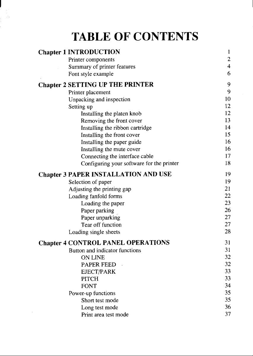
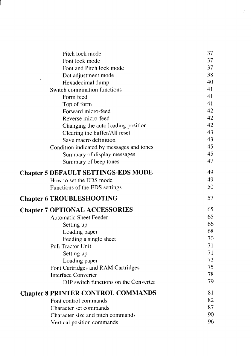

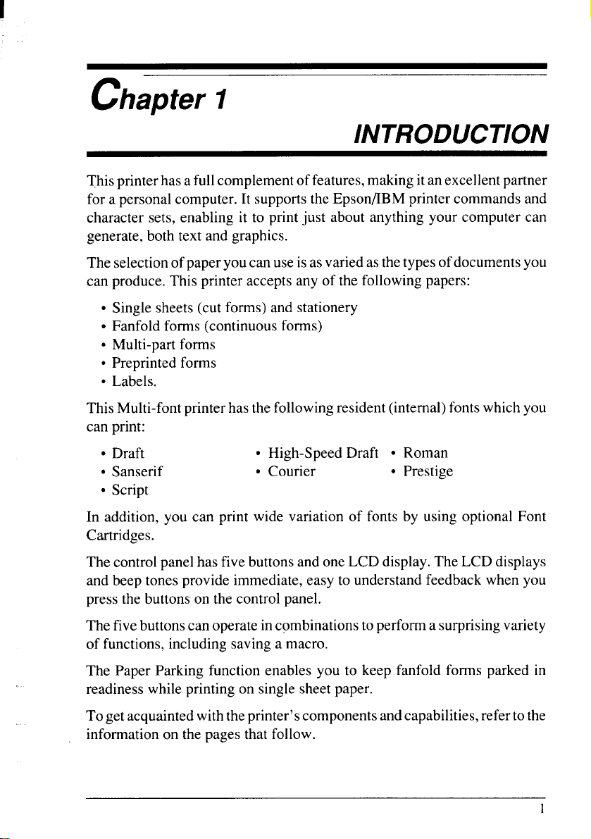
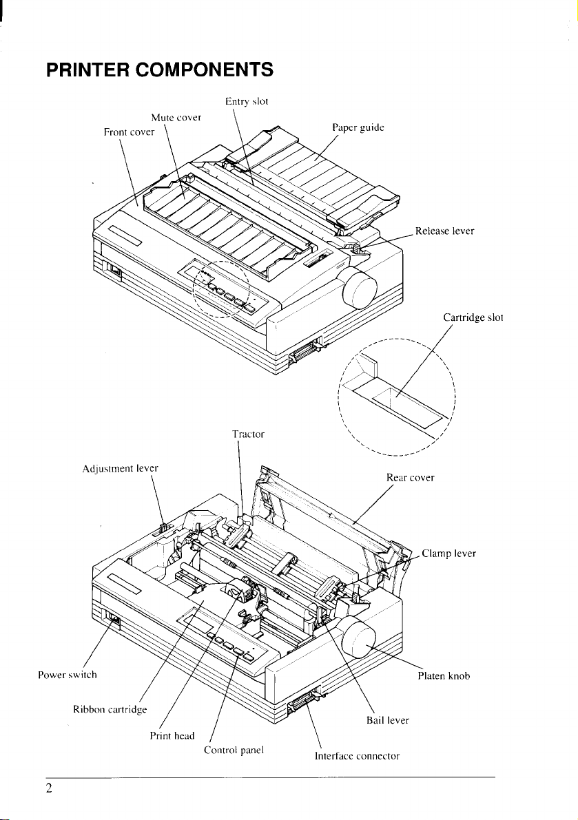
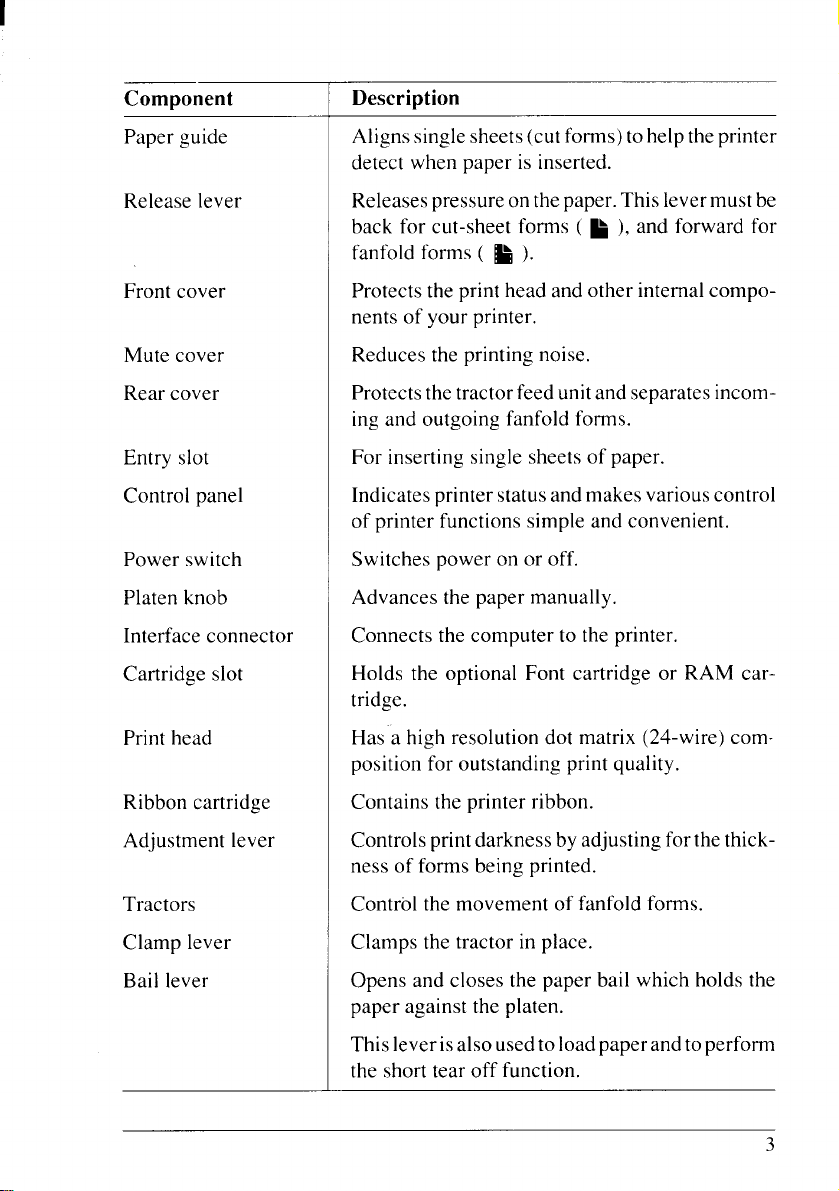
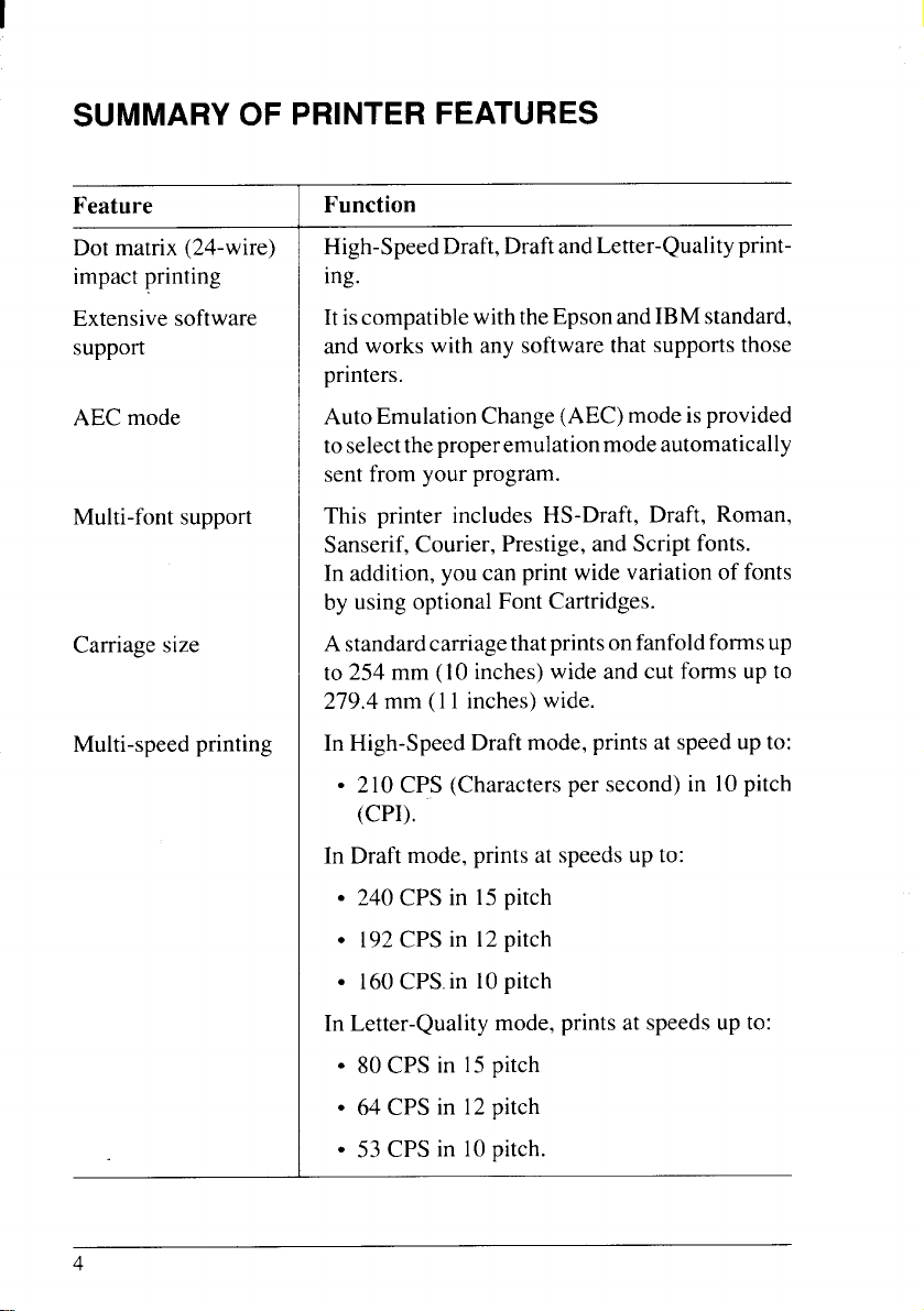
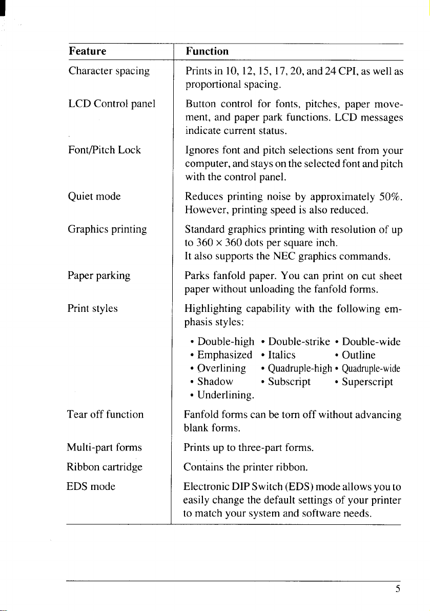
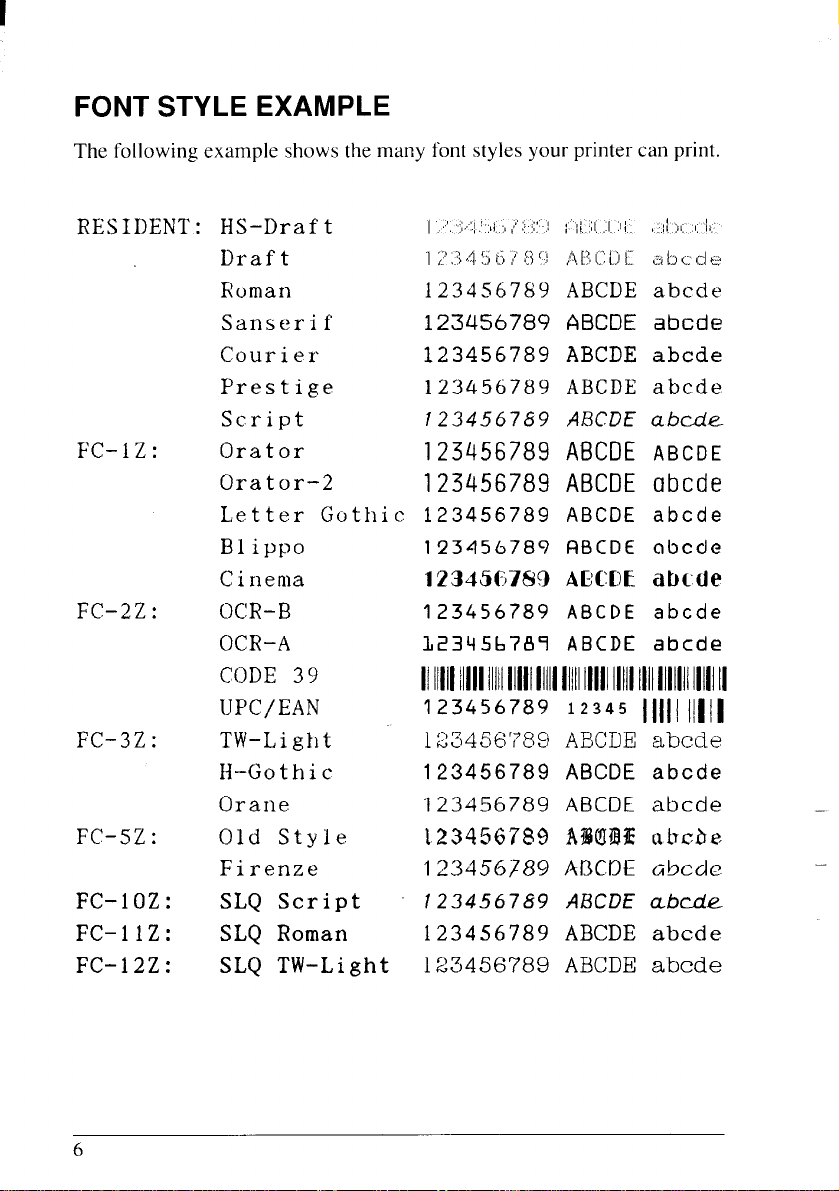
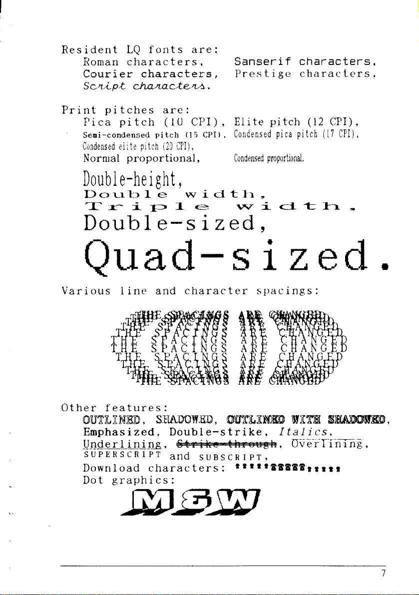

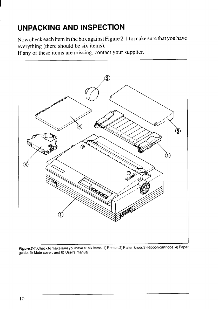

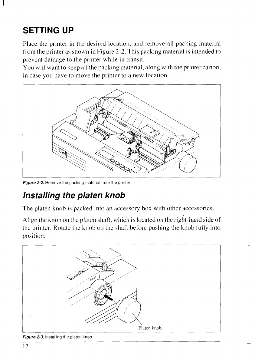
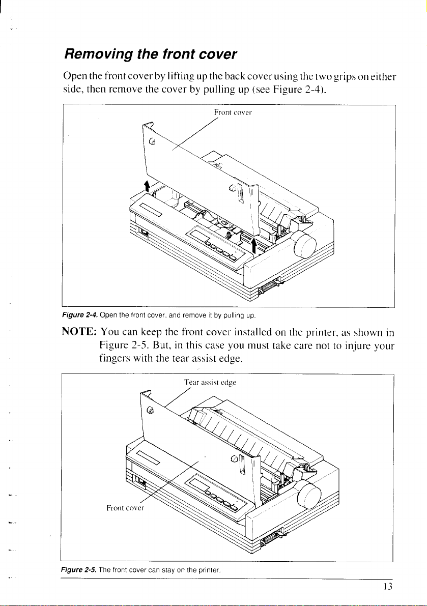
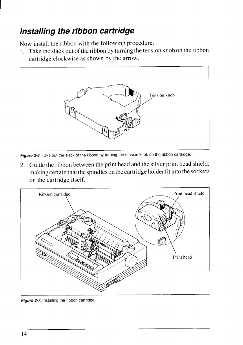
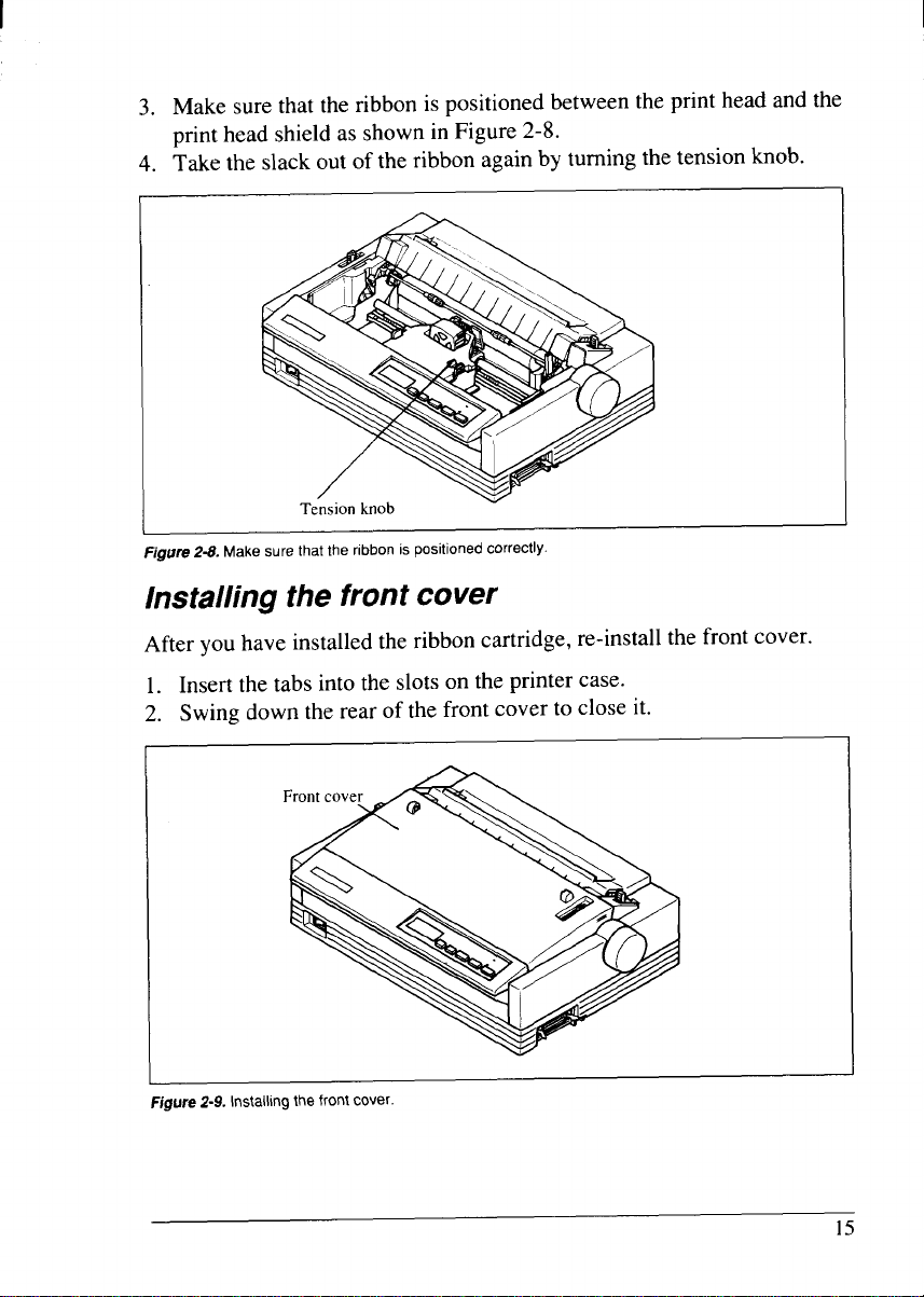
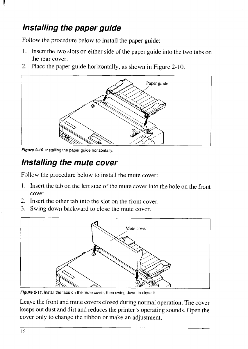
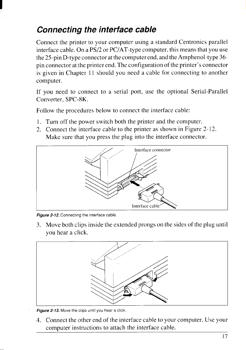
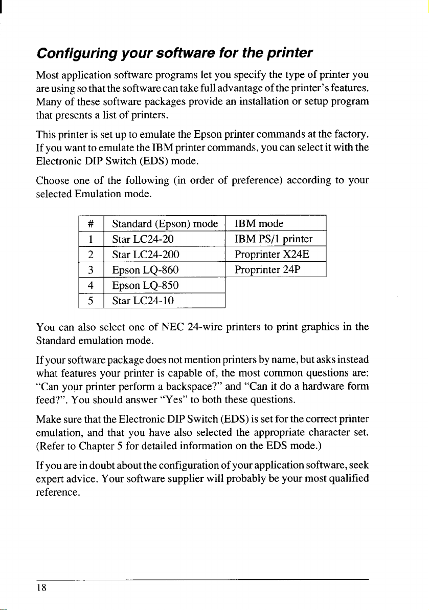
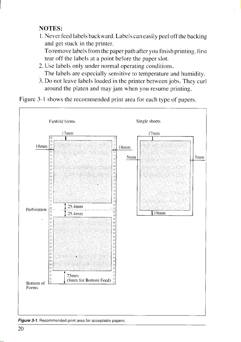

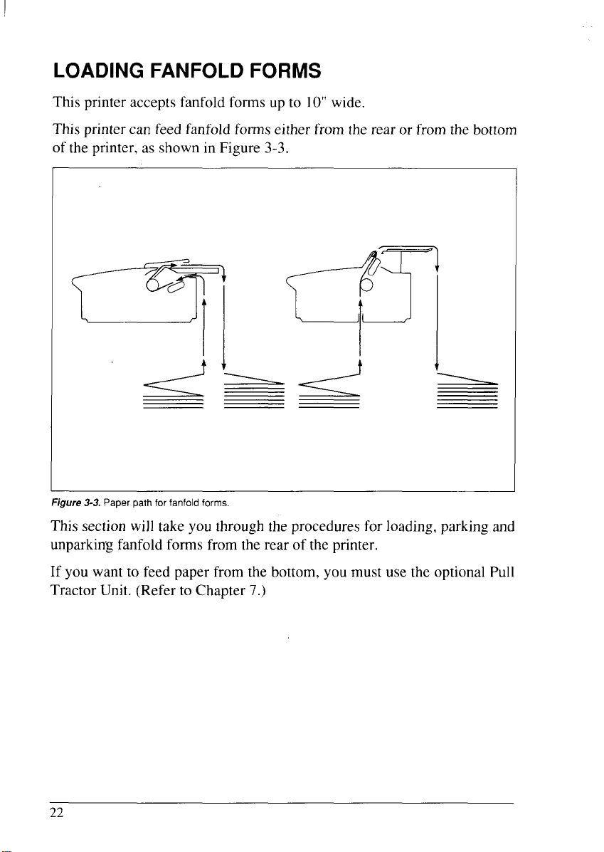


 Loading...