

Page 1

LC24-15II
MULTI-FONT
USERS MANUAL
NOT INTENDED FOR SALE
XBL 80825605
Page 2

VDE Statement
This device carries the VDE RFI protection mark to certify that it meets the radio interference
requirements of the Postal Ordinance No. 243/1991. The additional marking “Vfg. 243/P”
expresses in short form that this is a peripheral device (not operable alone) which only
individually meets the Class B RFI requirements in accordance with the DIN VDE 0878
part 3/11.89 and the Postal Ordinance 243/1991.
If this device is operated in conjunction with other devices within a set-up, in order to take
advantage of a “General (Operating) Authorization” in accordance with the Postal Ordinance
243/1991, the complete set-up must comply with the Class B limits in accordance with the
DIN VDE 0878 part 3/11.89, as well as satisfy the preconditions in accordance with § 2 and
the prerequisites in accordance with § 3 of the Postal Ordinance 243/1991.
As a rule, this is only fulfilled when the device is operated in a set-up which has been typetested and provided with a VDE RFI protection mark with the additional marking “Vfg 243”.
Machine Noise Information Ordinance 3. GSGV, January 18, 1991: The sound pressure
level at the operator position is equal or less than 70dB(A) according to ISO 7779.
The above statement applies only to printers marketed in Germany.
Trademark Acknowledgements
LC24-15II, LC24-15, NB24-15, IS-8XL, SF-15DJ, PT-15XJ: Star Micronics Co., Ltd.
IBM-PC, PS/2, PC-AT, Proprinter XL24E/XL24, PC-DOS: International Buisiness
Machines Corp.
Microsoft BASIC, MS-DOS: Microsoft Corporation
LQ-1050, LQ-1060: Seiko Epron Corp.
NOTICE
• All rights reserved. Reproduction of any part of this manual in any form whatsoever
without STAR’s express permission is forbidden.
• The contents of this manual are subject to change without notice.
• All efforts have been made to ensure the accuracy of the contents of this manual at the
time of press.
However, shoulld any errors be detected, STAR would greatly appreciate being
informed of them.
• The above notwithstanding, STAR can assume no responsibility for any errors in this manual.
Page 3

HOW TO USE THIS MANUAL
This manual is organized into eleven chapters. To learn how to make the best
use of your printer you are urged to read through chapters 1 through 6. Chapters
7 through 11 may be treated as a refernce guide for programming operations,
etc. It assumes a degree of knowledge of the operation of computers. The
chapters are as follows:
Chapter 1
-
Introduction
This chapter indicates the primary features of your ptinter, the names and
functions of the printer components, and an actual example of the many font
styles that your printer can produce.
Chapter 2
-
Setting Up the Printer
This chapter explains how to get the printer unpacked and set up. Read this
chapter before you do anything else.
Chapter 3
-
Paper Installation and Use
This chapter describes the instructions for printing such as selecting paper
types, adjusting the printing gap, and installing paper .
Chapter 4
-
Control Panel Operations
There are a number of controls on the front panel which perform various
functions related to paper handling, print modes and font selection.
After performinng the setup of the printer, read this chapter and try out the
procedures to find out how the printer works.
Chapter 5
-
Default Settings - EDS mode
This chapter explains how to set the Electronic DIP Switch (EDS) mode to
make your printer match your system and software needs.
Page 4

Chapter 6 - Troubleshooting
This section shows a list of check points to follow if your printer is not working
properly . It also includes details of some routine maintenance operations you
can perform yourself. It is not, however, a complete service manual. Call
your authorized service center if you are unsure of your ability to carry out
any maintenance or servicing operatioins on the printer .
Chapter 7
-
Optional Accessories
This chapter explains the optional accessories that are available for your
printer, and how to install and use them.
Chapter 8
-
Printer Control Commands
This chapter explains the software commands that are used to drive your
printer. This section is of use if you are writing or modifying programs to
take advantage of the printer’s features.
Chapter 9
-
Download Characters
This chapter explains the procedures to create your own characters.
Chapter 10
-
MS-DOS and Your Printer
Since the PS/2 or PC-AT family of computers running under MS-DOS is
currently the most popular configuration of microcomputer, we have included
a few hints and tips to help you use your printer with such systems.
Since virtually all PCs are sold with a Microsoft BASIC interpreter, we have
also included some hints, and a sample program in this language to demonstrate
the capabilities of the printer .
Chapter 1 1
-
Reference
This section provides refernces for your printer, such as specifications, the
pinout of interface connector, and the character tables.
The character table charts give the different character sets available.
Page 5

TABLE OF CONTENTS
Chapter 1 INTRODUCTION 1
Printer components 2
Summary of printer features 4
Font style example 6
Chapter 2 SETTING UP THE PRINTER 7
Printer placement 7
Unpacking and inspection 8
Setting up 9
Installing the platen knob 9
Installing the ribbon cartridge 10
Installing the paper guide 13
Connecting the interface cable 13
Configuring your software for the printer 15
Chapter 3 PAPER INSTALLATION AND USE 17
Selection of paper 17
Adjusting the printing gap 18
Loading single sheets 19
Loading and parking fanfold forms 22
Loading the paper 23
Paper parking 25
Paper unparking 26
Chapter 4 CONTROL PANEL OPERATIONS 27
Button and indicator functions 27
ON LINE 28
PAPER FEED 29
SET/EJECT 29
PITCH 30
FONT 30
Switch combination functions 31
Form feed 31
Top of form 32
Forward micro-feed 32
Reverse micro-feed 32
Page 6

Changing the auto loading position 32
Clearing the buffer/All reset 33
Save macro definition 34
Power-up functions 35
Short test mode 35
Long test mode 36
Print area test mode 37
Pitch lock mode 37
Font lock mode 37
Font and Pitch lock mode 37
Dot adjustment mode 38
Hexadecimal dump 39
Conditions indicated by beep tones 40
Chapter 5 DEFAULT SETTINGS
-
EDS MODE 41
How to set the EDS mode 41
Functions of the EDS settings 42
Chapter 6 TROUBLESHOOTING 47
Maintenance 52
Chapter 7 OPTIONAL ACCESSORIES 53
Automatic Sheet Feeder 53
Setting up 54
Loading paper 57
Pull Tractor Unit 59
Setting up 60
Loading paper 61
Serial Interface Cartridge 63
DIP switch functions on the serial interface cartridge 64
Chapter 8 PRITNER CONTROL COMMANDS 65
Font control commands 66
Character set commands 71
Character size and pitch commands 74
Page 7

vertical position commands 80
Horizontal position commads 86
Graphics commands 90
Download character commands 94
Other printer comands 97
Chapter 9 DOWNLOAD CHARACTERS 101
Defining your own characters with Standard mode 101
Assigning the character data 102
Assigning a value of character space 103
Sample program 104
Defining your own characters with IBM mode 106
Assigning the download character set 106
Assigning the character dot pattern 107
Assigning the Index T able data 108
Sample program 110
Chapter 10 MS-DOS AND YOUR PRINTER 113
Programming the printer with DOS commands 113
Programming with BASIC 116
Chapter 1 1 REFERENCE 123
Specifications 123
Pinout of interface connector 126
Parallel interface 126
Serial interface 127
Character sets 128
Standard character set #2 129
International character sets 131
IBM character set #2 132
Character set #1 139
IBM special character set 140
INDEX 141
COMMAND SUMMARY 145
Page 8

1
C
hapter 1
INTRODUCTION
This printer has a full complement of features, making it an excellent partner
for a personal computer. It supports the Epson/IBM printer commands and
character sets, enabling it to print just about anything your computer can
generate, both text and graphics.
The selection of paper you can use is as varied as the types of document you
can produce. This printer accepts any of the following kinds of paper:
• Single sheets (cut forms) and stationery
• Fanfold forms (continuous forms)
• Multi-part forms (up to 3-ply)
• Preprinted forms
This Multi-font printer has the following resident (internal) fonts:
• Draft
• Roman
• Sanserif
• Courier
• Prestige
• Script
The control panel has five buttons and eleven indicators. The indicator display
and beep tones provide immediate, easy-to-understand feedback when you
press the buttons on the control panel.
The five buttons can operate in combinations to perform a surprising variety
of functions, including saving a micro.
An additional useful feature is the ability to switch easily between printing
on fanfold paper and printing on single sheets. A simple control panel operation
lets you “park” the fanfold paper, so that you do not have to remove the
fanfold paper from the printer. When you want to resume printing on the
fanfold paper, you can simply “unpark” it.
T o get acquainted with the printer’s components and capabilities, refer to the
information on the pages that follow .
Page 9
2
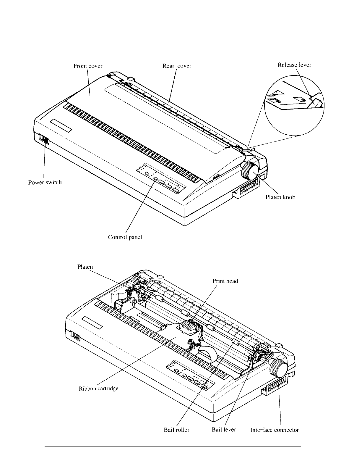
PRINTER COMPONENTS
Page 10
3
Component Description
Paper guide Aligns single sheets (cut forms) to help the printer
detect when paper is inserted.
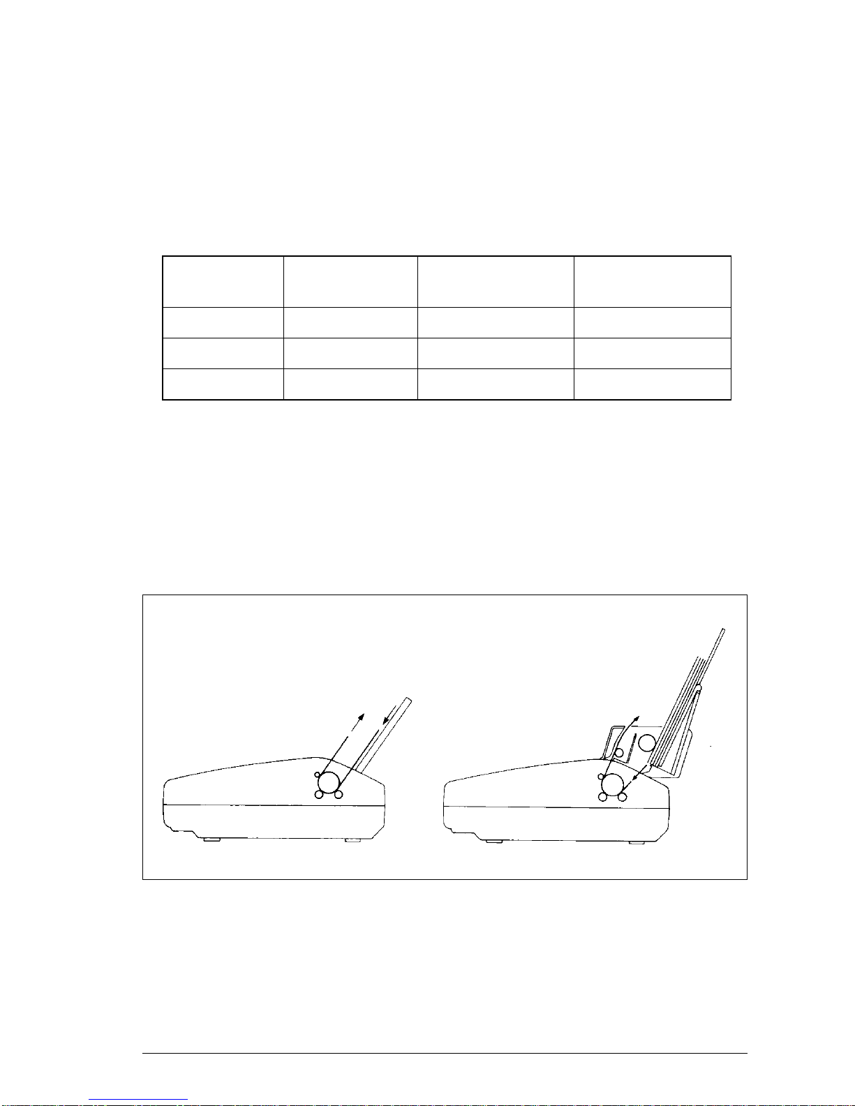
Release lever Releases pressure on the paper. This lever must
be back for cut forms ( ), and forward for fanfold
forms ( ).
Front cover Protects the print head and other internal compo-
nents of your printer.
Rear cover Protects the tractor feed unit and separates in-
coming and outgoing fanfold forms.
Entry slot For inserting single sheets of paper .
Control panel Indicates printer status and makes control of printer
functions simple and convenient.
Power switch Switches power on or off.
Platen knob For advancing the paper manually.
Interface connector Connects the computer to the printer .
Print head Has a high resolution dot matrix (24-wire) com-
position for outstanding print quality.
Ribbon cartridge Contains the printer ribbon.
Adjustment lever Controls print darkness by adjusting for the
thickness of forms being printed.
Tractors Control the movement of fanfold forms.
Clamp lever Clamps the tractor in place.
Bail lever Opens and closes the paper bail which holds the
paper against the platen.
Page 11

4
SUMMAR Y OF PRINTER FEATURES
Feature Function
Dot matrix (24-wire) Draft and Letter-Quality printing.
impact printing
Extensive software The printer is compatible with the Epson and IBM
support standards, and works with any software that
supports those printers.
Multi-font support This printer includes Draft, Roman, Sanserif,
Courier, Prestige, and Script fonts.
Carriage size A wide carriage that prints on cut forms up to 420
mm (16.5 inches) wide and fanfold forms up to
406 mm (16 inches)wide.
Multi-speed printing In Draft mode, prints at speeds up to:
• 300 CPS in 15 pitch
• 240 CPS in 12 pitch
• 200 CPS in 10 pitch
In Letter-Quality mode, prints at speeds up to:
• 100 CPS in 15 pitch
• 80 CPS in 12 pitch
• 67 CPS in 10 pitch.
Charactor spacing Prints in 10, 12, 15, 17, and 20 CPI, as well as
proportional spacing.
Control panel Button control for fonts, pitches, paper movement,
and paper park functions.
Font/Pitch Lock Ignores font and pitch selections sent from your
computer , and stays on the font and pitch selected
from the control panel.
Quiet mode Reduces printing noise by approximately 50%.
However , printing speed is also reduced.
Graphics printing Standard graphics printing with resolution of up
to 360 x 360 dots per square inch. It also supports
the NEC graphics commands.
Page 12
5
Feature Function
Paper parking Parks fanfold paper. You can print on cut sheet
paper without unloading the fanfold forms.
Print styles Highlighting capability with the following em-
phasis styles:
• Double-high • Double-strike • Double-wide
• Emphasized • Italics • Outline
• Overlining • Shadow • Subscript
• Superscript • Underlining.
T ear off function Fanfold forms can be removed without advancing
blank forms.
Multi-part forms Prints up to three-part forms.
Ribbon cartridge Contains the printer ribbon.
EDS mode Electronic DIP Switch (EDS) mode allows you
to easily change the default settings of your printer
to match your system and software needs.
Page 13

6
FONT STYLE EXAMPLE
The following example shows the many font styles your printer can print.
Page 14

7
C
hapter 2
SETTING UP THE PRINTER
This chapter describes the following procedures for setting up your new
printer. If you have optional accessories, refer to Chapter 7 after setting up
the printer .
• Printer placement
• Unpacking the printer
• Installing the platen knob
• Installing the ribbon cartridge
• Connecting the printer to your computer
• Configuring your software for the printer
PRINTER PLACEMENT
Before you start setting up your printer, meke sure that you have a suitable
place on which to locate it. By “a suitable place”, we mean:
• A firm, level surface which is fairly vivration-free
• Away from excessive heat (such as direct sunlight, heaters, etc)
• Away from excessive humidity
• Away from excessive dust
• A steady power supply that is not subject to power surges should be
connected to the printer .
For example, do not connect the printer to the same circuit as a large,
noise-producing appliance such as a refrigerator or an air conditioner .
• Make sure the line voltage is the voltage specified on the printer’s
identification plate.
• If you are connecting your printer with a parallel interface, make sure that
the cable is within 2m (6ft) of the printer . An RS-232 connection using the
optional IS-8XL interface cartridge can be made over longer distances.
Page 15
8
UNPACKING AND INSPECTION
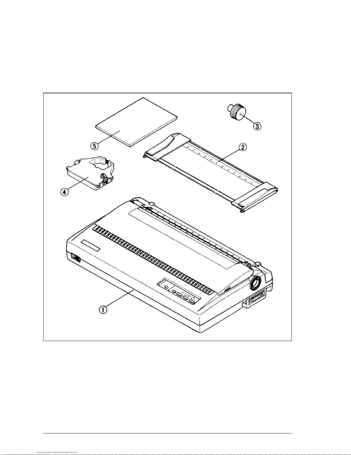
Now check each item in the box against Figure 2-1 to make sure that you
have everything (there sholud be five items).
If any of these items are missing, contact your supplier.
Figure 2-1.
Check to make sure you have all five items: 1) Printer , 2) Paper guide, 3) Platen knob, 4) Ribbon
cartridge, and 5) User’s manual.
The optional accessories which you may have ordered with your printer are:
• Serial interface cartridge (IS-8XL)
• Automatic sheet feeder (SF-15DJ)
• Pull tractor unit (PT-15XJ)
For details of the optional accessories, refer to Chapter 7.
Page 16
9
SETTING UP
Place the printer in the desired location, and remove all packing material
from the printer . This packing material is intended to prevent damage to the
printer while in transit.
You will want to keep all the packing material, along with the printer carton,
in case you have to move the printer to a new location.
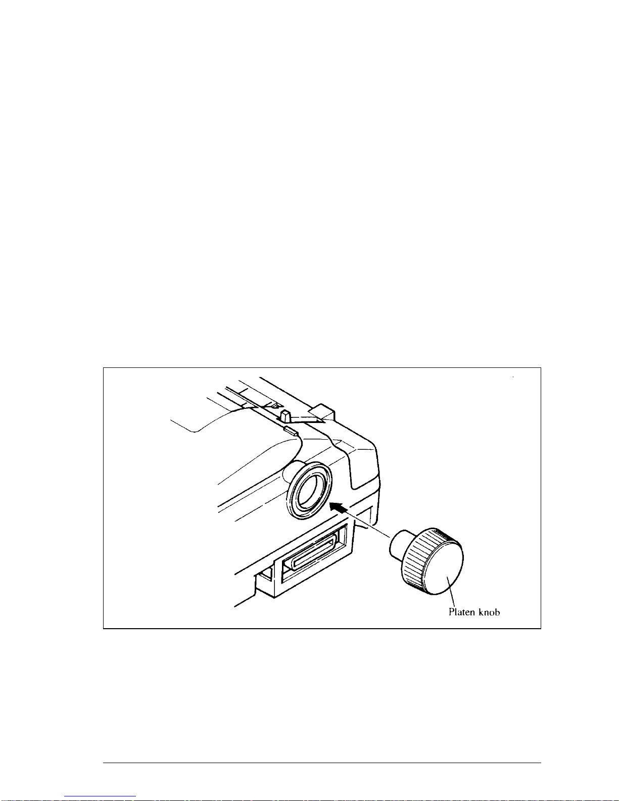
Installing the platen knob
The platen knob is packed into a recess of the packing material which held
your printer inside the printer carton. Be careful to remove the knob before
disposing of the package.
Mount the knob on the platen shaft, which is located on the right-hand side
of the printer. Rotate the knob on the shaft before pushing the knob fully into
position.
Figure 2-2.
Installing the platen knob.
Page 17
10
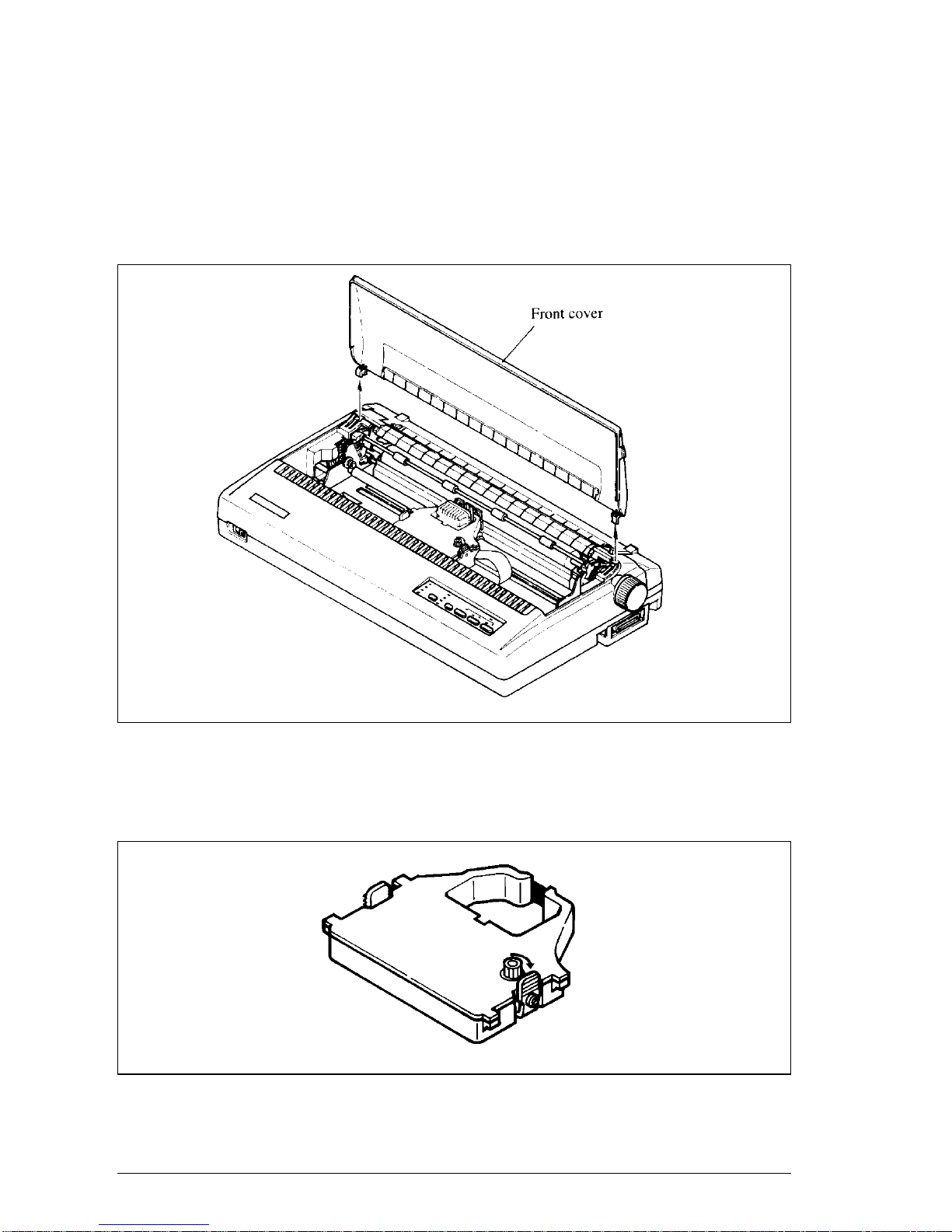
Installing the ribbon cartridge
Now install the ribbon by the following procedure.
1. Remove the front cover by lifting the front (using the two grips at the
sides), and pulling towards you.
Figure 2-3.
Remove the front cover to install the ribbon cartridge.
2. Take up the slack in the ribbon by turning the tension knob on the ribbon
cartridge clockwise as shown by the arrow.
Figure 2-4.
Take up the slack in the ribbon by turning the tension knob on the ribbon cartridge.
Page 18
11
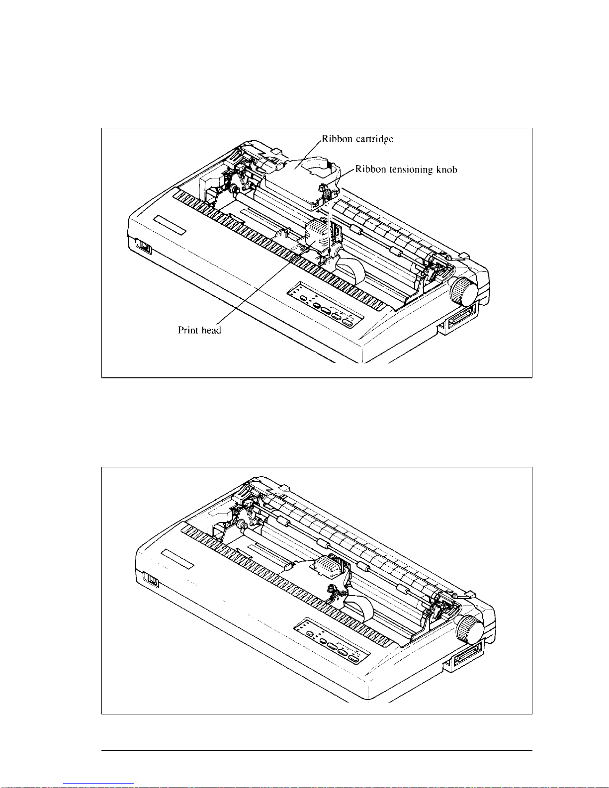
3. Guide the ribbon between the print head and the silver print head shield,
making certain that the spindles on the cartridge holder fit into the sockets
on the cartridge itself.
Figure 2-5.
Install the ribbon cartridge.
4. Make sure that the ribbon is positioned between the print head and the
print head shield as shown in Figure 2-5.
5. Take up the slack in the ribbon again by turning the tension knob.
Figure 2-6. Make sure that the ribbon is positioned correctly.
Page 19
12
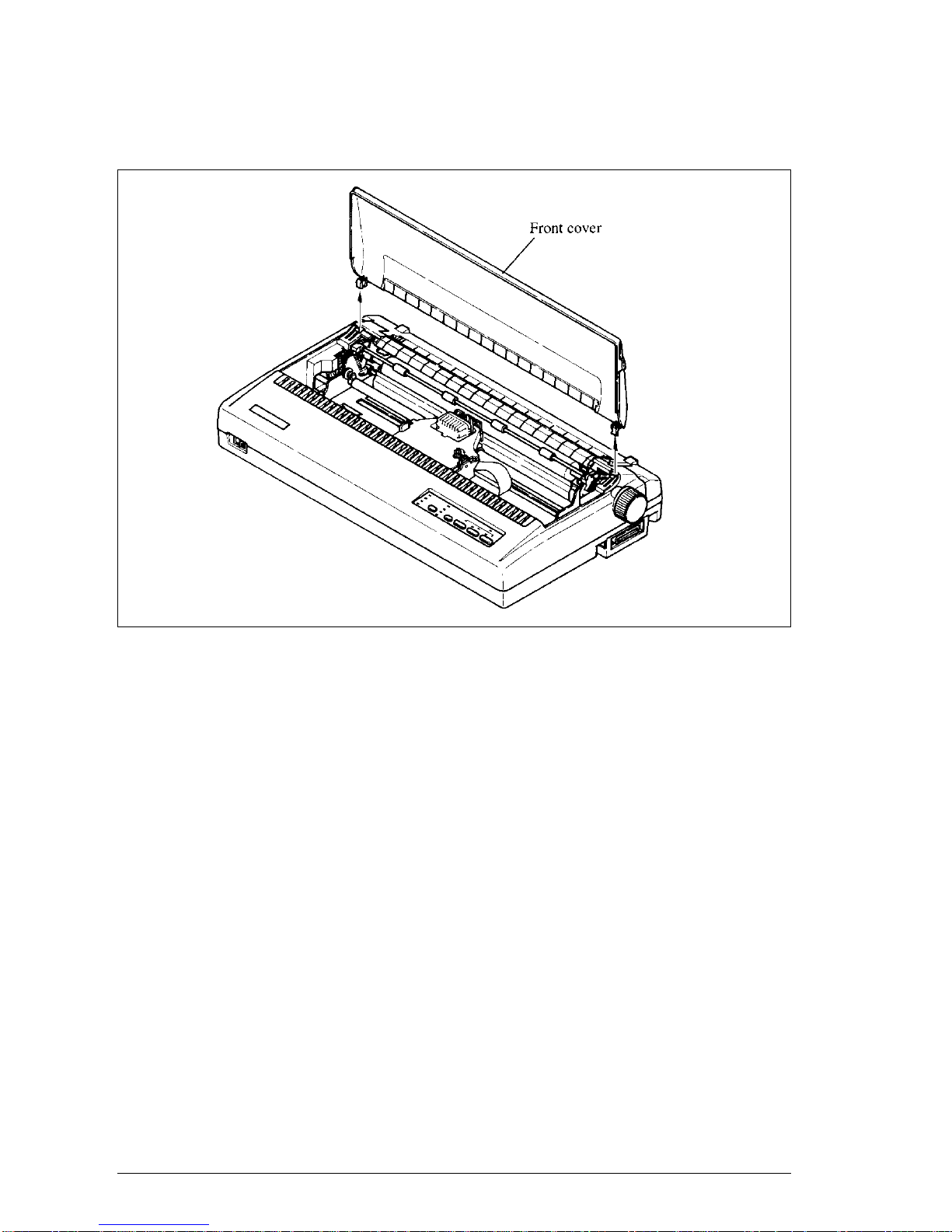
6. Hold the front cover upright and engage the tabs at the back. Then swing
the front edge down until the cover is closed.
Figure 2-7.
Swing down the front cover after inserting the tabs into the slots of the printer case.
Leave the front cover closed during normal operation. The cover keeps out
dust and dirt and reduces the printer’s operating noise. Open the cover only
to change the ribbon or make an adjustment.
Page 20
13
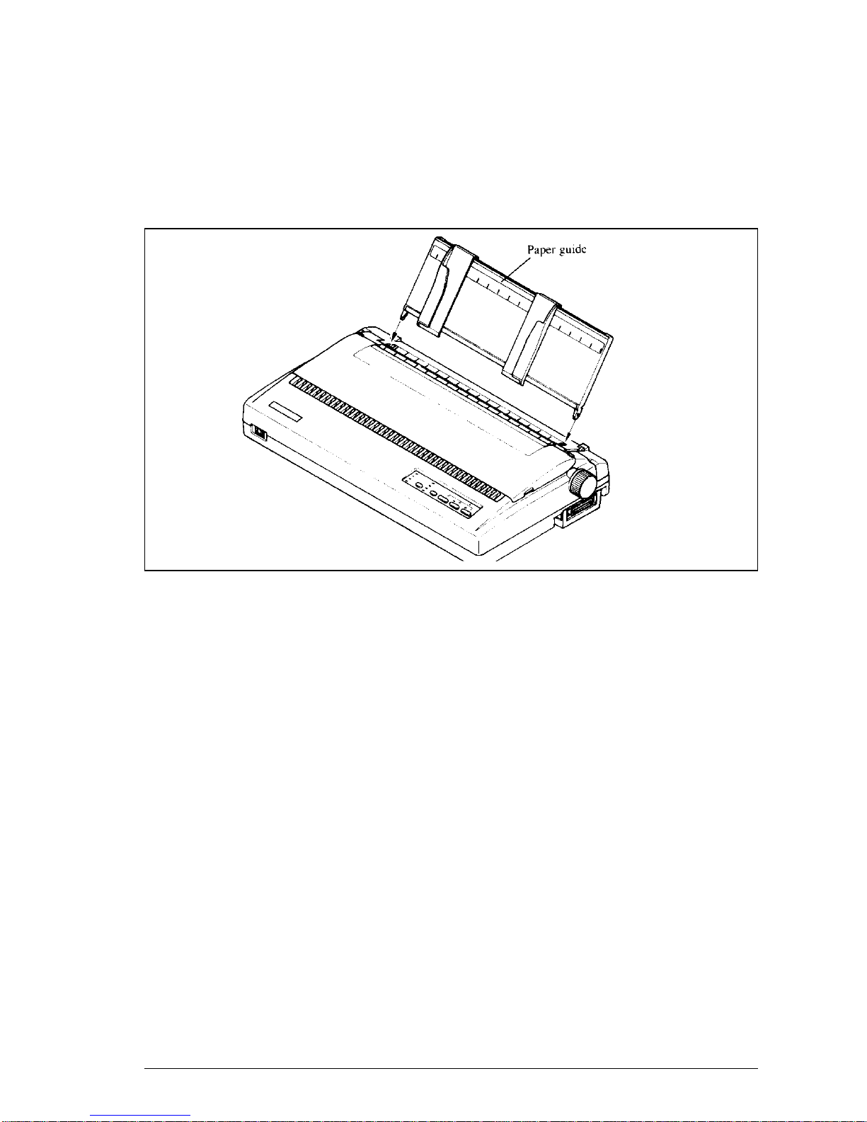
Installing the paper guide
Follow the procedure below to install the paper guide:
1. Insert the two slots on either side of the paper guide into the two tabs on
the rear cover, as shown in Figure 2-8.
Figure 2-8.
Install the paper guide.
2. Place the paper guide horizontally when using fanfold paper, or vertically
when using single sheets.
Connecting the interface cable
The printer and computer are connected by a cable along which the computer
transmits the documents that you want to print. A cable is not supplied as
standard equipmemt with this printer. There are two sorts of cable that you
can use: a standard 36-pin Centronics parallel cable or the serial cable that
you can purchase as an option with the printer.
Connecting the printer to a computer using a parallel cable is generally simpler;
however, the length of the parallel cable should not be more than 6 feet,
otherwise the transfer of information between your computer and the printer
may be impaired. A serial connection can, for all practical purposes, be as
long as you like, but is a little more complicated to set up. Buy the type of
cable which will best suit your needs.
If you need to connect to a serial port, use the optional Serial interface
cartridge, IS-8XL.
Page 21
14
The parellel cable which you can use has a 25-pin D-type plug at one end,
and a 36-pin Centronics connector at the other .
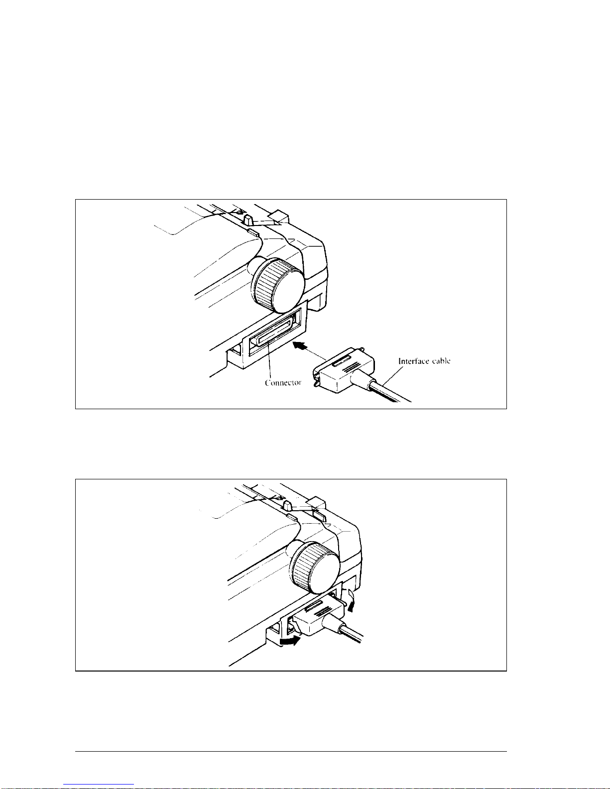
Follow the procedure below to connect the interface cable:
1. Turn off the power switch on both the printer and the computer.
2. Plug the cable’s Centronics connector into the socket on the side of the
printer as shown in Figure 2-9.
Make sure that you press the plug into the interface connector .
Figure 2-9.
Connector the interface cable.
3. Move both clips inside the extended prongs on the sides of the plug until
you hear a click.
Figure 2-10.
Move the clips until you hear a click.
4. Plug the 25-way plug into the parallel socket on your computer. This will
probably be labelled “Printer”, “Parallel”, “PRN”, “LPT1” or something
similar .
Page 22
15
Configuring your software for the printer
Most application software programs let you specify the type of printer you
are using so that the software can take full advantage of the printer’s features.
Many of these software packages provide an installation or setup program
that presents a list of printers.
This printer is preset to emulate the Epson printer commands. If you want to
emulate the IBM printer commands, you can select IBM with the Electronic
DIP Switch (EDS) mode.
Choose one of the following (in the order of preference) according to your
selected Emulation mode:
# Standard (Epson) mode IBM mode
1 Star LC24-15II Proprinter XL24E
2 Star LC24-15 Proprinter XL24
3 Star NB24-15
4 Epson LQ-1060
5 Epson LQ-1050
If your software package does not mention printers by name, but asks instead
what features your printer is capable of, the most common questions are:
“Can your printer perform a backspace?” and “Can it do a hardware form
feed?” you should answer “Yes” to both these questions.
Make sure that the Electronic DIP Switch (EDS) is set for the correct printer
emulation, and that you have also selected the appropriate character set.
(Refer to Chapter 5 for detailed information on the EDS mode.)
NOTE:If you are in doubt about the configuration of your application
software, seek expert advice. Your software supplier will probably
be your most qualified reference.
Page 23

16
MEMO
Page 24

17
C
hapter 3
PAPER INSTALLATION AND USE
This chapter describes instructions for printing such as selecting paper types,
adjusting the printing gap, and installing paper .
SELECTION OF PAPER
You can use any of the following types of paper with your printer: single
sheets, fanfold paper and multi-part forms.
• Single sheets (cut forms) and stationery
Single sheets are simply individual, unconnected pieces of paper, and are
also sometimes referred to as cut sheets.
Up to fifty single sheets can be stacked and automatically fed into the
printer by using the optional Automatic Sheet Feeder (SF-15DJ).
• Fanfold forms
Fanfold forms are sheets of paper joined with perforations. Fanfold forms
usually have a column of holes punched into each edge which enables the
printer to grip the paper as it feeds it through. Fanfold paper is also
sometimes referred to as computer paper, continuous forms or sprocket
forms.
You can feed the fanfold forms from the rear of the printer as standard.
You can also use the optional Pull tractor unit (PT-15XJ) to feed fanfold
paper . Printing on or near the perforations of continuous fanfold forms
may reduce printing quality , misalign the fanfold forms, or cause a paper jam.
• Multi-part forms
Multi-part forms consist of several sheets, one on top of another, enabling
several copies to be made simultaneously . Multi-part forms may be joined
together, as fanfold stationery. If you want to use multi-part forms, use the
typethat has both side edges glued together. Do not use forms that have
more than three parts.
It is recommended that you load multi-part forms using the optional Pull
tractor unit.
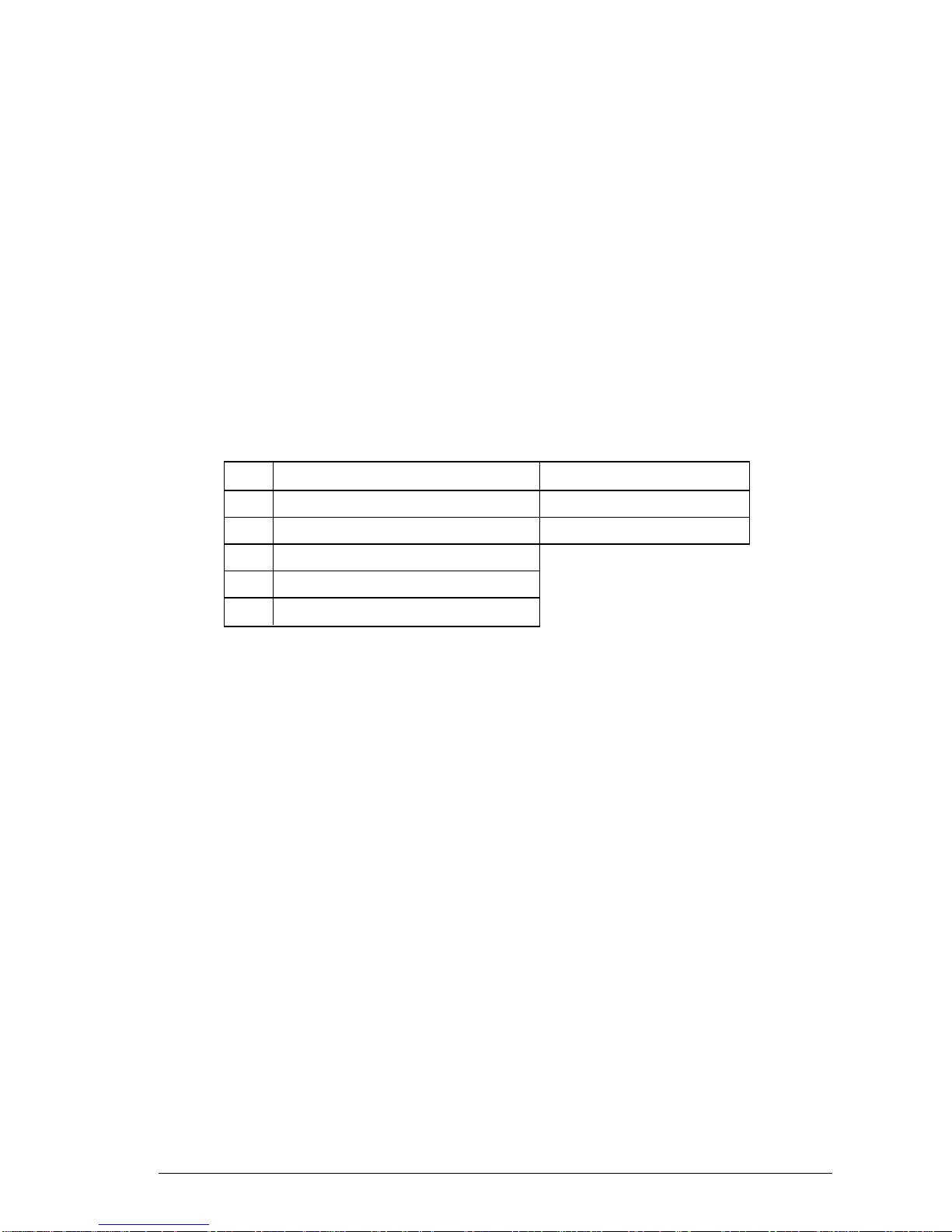
Figure 3-1 shows the recommended print area for each type of paper .
Page 25
18
Figure 3-1.
Recommended print area for acceptable types of paper.
ADJUSTING THE PRINTING GAP
Paper comes in different weights, normally quoted in gsm (grams per square
meter). Typical figures are 80 gsm and 100 gsm. Heavier paper is thicker.
Also, multi-part forms are generally thicker than single sheets or ordinary
fanfold paper .
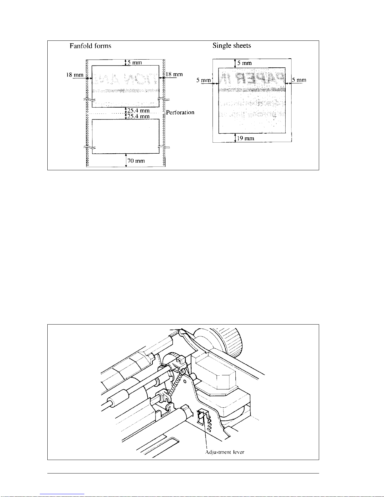
The distance between the print head and the platen can be adjusted to suit the
paper thickness. The adjustment lever is located inside the printer’s main
body, at the right-hand end of the platen. There are five settings. Push the
lever up to narrow the gap between the print head and the platen, and down
to widen the gap. The top positon is referred to as position 1, and the lowest
position as position 5. Position 2 is the one most suited to single sheets.
Figure 3-2.
Location of the adjustment lever.
Page 26
19
It is a good idea to try out different settings in order to ascertain which
setting gives the best results in terms of print quality.
NOTE: Printing with an inappropriate gap may drastically shorten the life
of the print head.
The table below gives recommended settings:
Paper Type
Weight(g/m
2
) Thickness(mm) Recommended
(Each sheet) (T otal) Lever position
Single 52 to 90 0.07 to 0.12 2 or 3
2-ply 40 t o 52 0.12 to 0.14 2 or 3
3-ply 40 t o 52 0.18 to 0.21 3 or 4
LOADING SINGLE SHEETS
This section will take you through the procedure for loading single sheets of
paper. If you are using the optional Automatic Sheet Feeder (SF-15DJ),
refer to Chapter 7.
The paper path fo rcut forms is shown in Figure 3-3.
Figure 3-3.
Paper path for cut forms.
Page 27

20
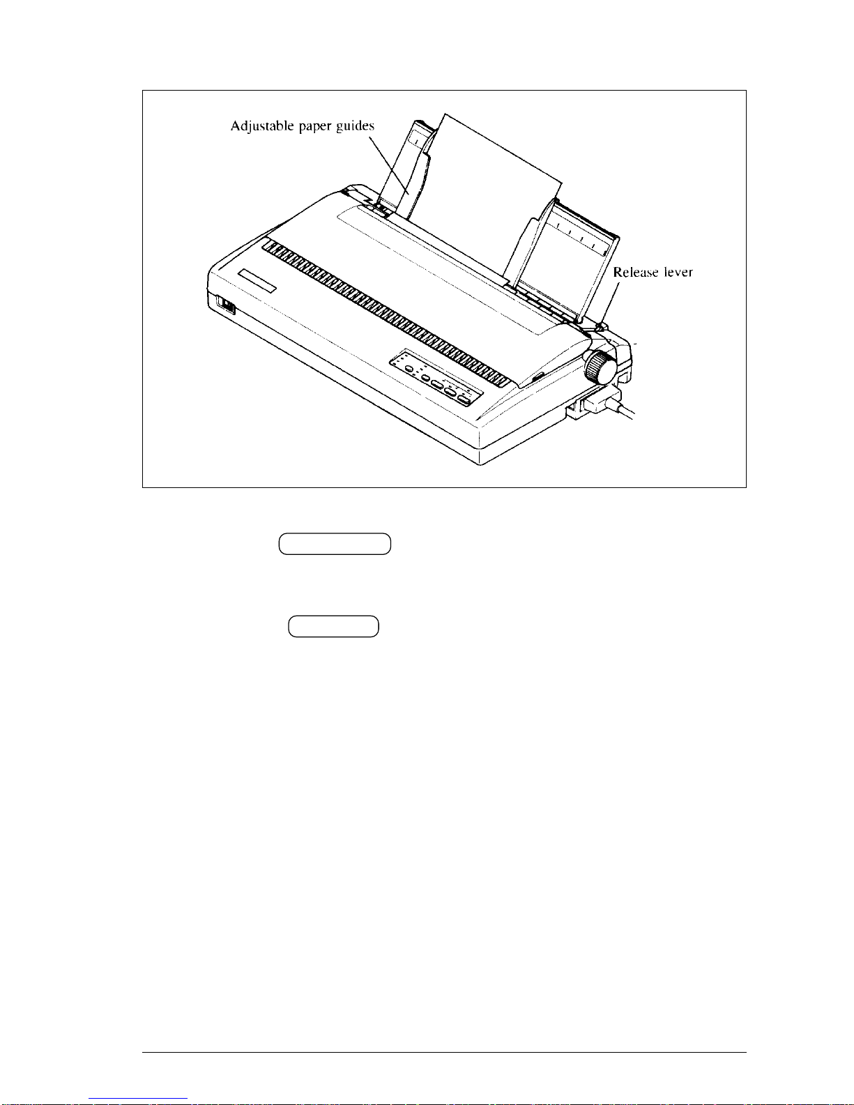
1. Raise the paper guide vertically on the rear cover..
Figure 3-4.
Raise the paper guide vertically.
2. Turn ON the power at the switch located at the front of the printer. The
printer will beep, indicationg that there is no paper in position for printing.
The POWER indicator will also flash to confirm this.
3. Make sure that the release lever is at rear position ( ).
If fanfold paper is already mounted in the printer, press the SET/EJECT
button to park the paper in the off-line state, then move the release lever
toward the rear of the printer.
4. Adjust the left paper guide to the desired left position by moving it
horizontally in either direction.
5. Adjust the right paper guide to accommodate the width of the paper.
The guides should be adjusted to restrict the amount of horizontal play
while allowing the paper to slide up and down freely between the two
paper guides. The ideal distance between paper ream and paper guides is
0.25 mm (0.01”) on both sides at the narrowest part of the paper guides.
6. Place a single sheet between the guides, facing the side on which you want
to print towards the back of the printer . Gently push the paper down in the
guides until you feel it stop.
Page 28
21
Figure 3-5.
Place a single sheet between the guides
7. Now press the SET/EJECT button. The paper will be fed into the printer
and adjusted past the print head to a position ready for printing.
8. If you want to set the paper to a different position, set the printer of f-line
by pressing the ON LINE button, then set the paper by using the microfeed function. (For details, refer to Chapter 4.)
Now you are ready to start printing.
Page 29
22
LOADING AND PARKING F ANFOLD FORMS
This printer accepts forms up to 16” wide.
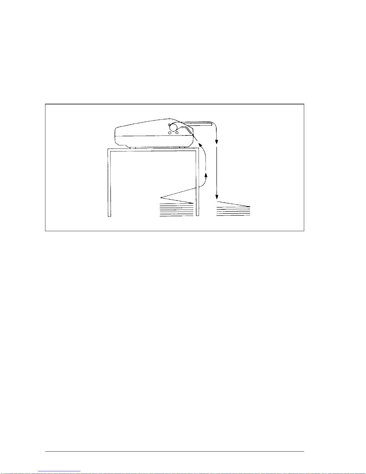
The printer can feed fanfold forms using either the standard tractor unit or
the optional Pull tractor unit (PT-15XJ), as shown in Figure 3-6.
Figure 3-6.
Paper path for fanfold forms.
This section will take you through the procedures for loading, parking and
unparking fanfold forms.
Page 30
23
Loading the paper
If you are going to load the paper with the optional Pull tractor unit, refer to
Chapter 7.
1. Place a stack of fanfold paper behind and at least one page-length below
the printer .
2. Turn the printer’s power OFF.
3. Push the release lever forward. This has the effect of releasing the paper
from the platen roller, and engaging the tractor feed.
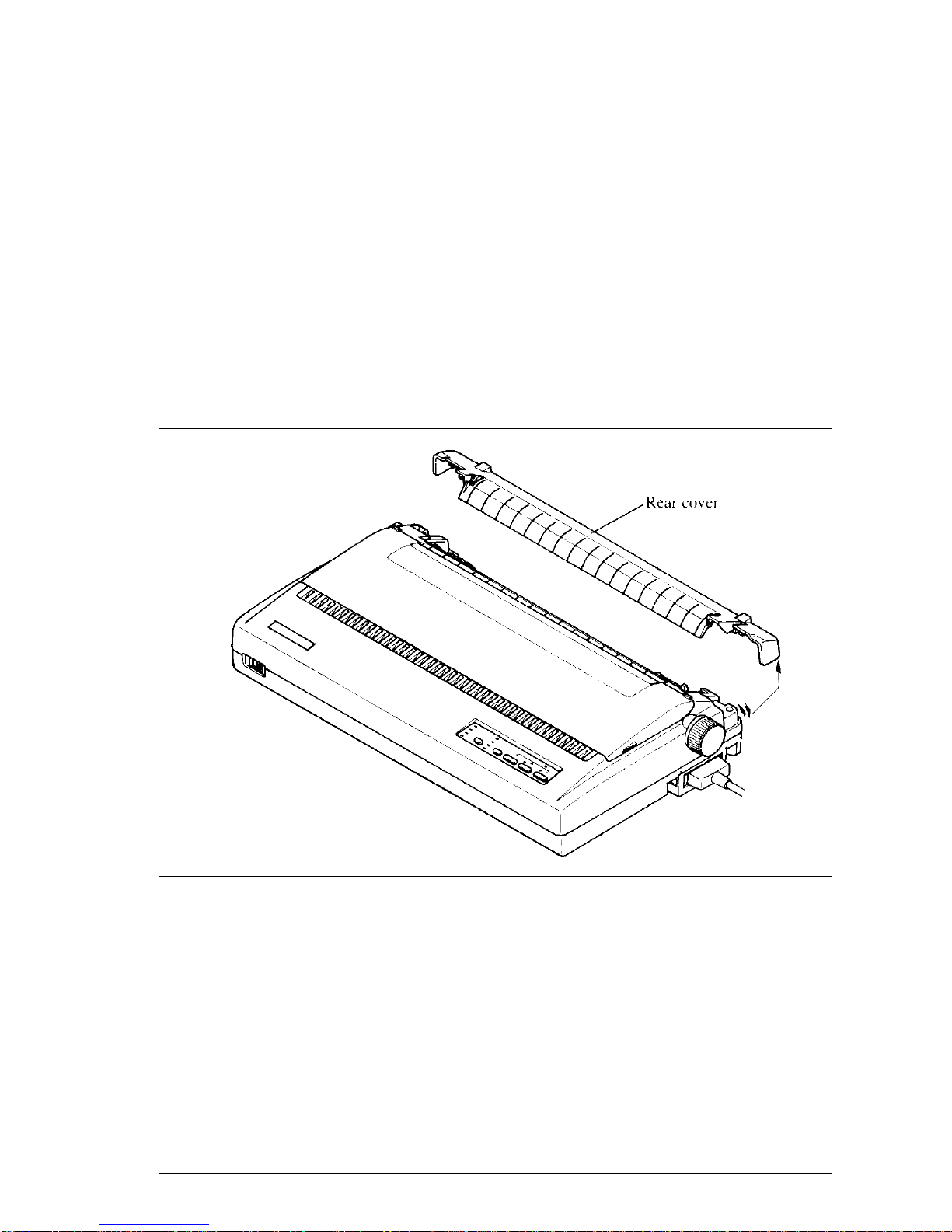
4. Remove the rear cover. Grip it by its rear edge and lift upwards and
backwards as in Figure 3-7.
Figure 3-7.
Remove the rear cover.
5. With the tractor covers open, mount the paper by aligning holes with the
pins on the tracctor unit.
6. Adjust the spacing of the tractor units by sliding them along the bar,
using the clamp lever at the back of each unit to release them and lock
them in position. The unit is released when the clamp lever is down and
locked when the clamp lever is up.
Page 31

24
Figure 3-8.
Mount the fanfold paper over the tractor units.
7. Now close the tractor covers, again making sure that the paper holes are
aligned with the pins on the tractor units. If they are not aligned properly ,
you will have problems with paper feeding, possibly resulting in tearing
and jamming of the paper .
8. Remount the rear cover. Hold it tilted upward and insert the four tabs at
the front into their slots. Then rotate the cover downwards, pressing down
on the thumb pads on the left and right to snap it into place.
9. Mount the paper guide in the horizontal position, as shown in Figure 3-9.
This will separate the printed from the unprinted paper .
10.Turn ON the power at the switch located at the front of the printer . The
printer will beep, indicating that the paper is not yet fully loaded. The
POWER indicator will also flash to confirm this.
11.Now press the SET/EJECT button. The paper will be fed and adjusted
past the print head to a position ready for printing..
12.If you want to set the paper to a different position, set the printer off-line
by pressing the ON LINE button, then set the paper by using the microfeed function. (For details, refer to Chapter 4.)
Page 32

25
Figure 3-9.
Close the rear cover, then set the paper guide horizontally.
Paper parking
After loading fanfold paper from the rear of the printer, you do not have to
unload it when you want to print on a single sheet. The printer will “park” it
for you if you follow the procedure below .
1. To begin paper parking, start with power ON, fanfold paper loaded in
printing position, and the release lever forward.
2. Press the ON LINE button on the control panel to set the printer off-line.
The ON LINE indicator will turn off.
3. Tear off the printed form at the last perforation, leaving not more than
about half a page showing above the top cover. If necessary, press the
PAPER FEED button to feed paper forward until a perforation is located
just above the front cover, and tear there.
4. Press the SET/EJECT button on the control panel.
The printer will automatically feed the fanfold form backward until the
paper is completely free of the platen.
5. Move the release lever to the back.
6. Mount the paper guide in the upright position.
Page 33

26
Now you can load single sheets, as explained previously. The fanfold paper
remains parked at the back of the printer .
NOTE: You cannot park the fanfold paper if you have loaded it with the
optional pull tractor unit.
Paper unparking
When you want to resume using fanfold paper , the procedure is as follows.
1. Remove all single sheets from the printer .
2. Mount the paper guide in the horizontal position.
3. Move the release lever to the front.
4. Press the SET/EJECT button. The printer will automatically feed the
parked fanfold paper back into position for printing.
NOTE: The printer beeps intermittently if you move the release lever while
the paper is loaded.
Page 34

27
C
hapter 4
CONTROL PANEL OPERATIONS
The control panel buttons can be pressed individually to perform the operations
indicated by their names. Other functions can be achieved by pressing the
control panel buttons in combination, or by holding these buttons down when
you turn the printer’s power on.
This chapter explains all the button and indicator functions.
• Pause printing
• Feed paper (fast and slow, forward and reverse)
• Park fanfold forms
• Set the top-of-form position
• Select the print pitch
• Select a font
• Save macro definition
• Clear the printer’s buffer
• Print test patterns
• Prevent software from changing the panel pitch and font selections
• Adjust the print alignment for bi-directional printing
• Print a hexadecimal dump
BUTTON AND INDICATOR FUNCTIONS
The printer is equipped with five buttons on the control panel. From left to
right they are FONT , PITCH , SET/EJECT , PAPER FEED and
ON LINE .
The following is a brief guide to the buttons and indicators on the control
panel.
Figure 4-1.
Control panel.
Page 35

28
ON LINE
The ON LINE button sets the printer on-line and off-line. The status changes
each time you press the button.
When the printer is on-line, it can receive and print data from the computer .
This status is indicated by the ON LINE indicator being lit. When the printer
is off-line, it stops printing and sends teh computer a signal indicating that it
cannot accept data.
The printe powers up in the on-line status when paper is loaded. If paper is
not loaded, the printer powers up off-line with the POWER indicator blinking.
When you load paper , the printer goes on-line.
You will want to press the ON LINE button:
• Before and after any other panel operation
The other panel buttons operate in the off-line state. Press the ON LINE
button to go off-line. After performing teh panel operation(s), press the
ON LINE button again to go back on-line.
• To pause during printing
If you press the ON LINE button during printing, the printer stops printing
and goes off-line, allowing you to check the printout or change a control
panel setting. Printing resumes when you press the ON LINE button again
to go back on-line.
• To cut fanfold forms at the end of printing
When you hold down the ON LINE button and press the PAPER FEED
button down for one second with the fanfold forms fed through by the standard
tractor unit, the printer goes off-line, then the printer feeds the paper forward
approximately two inches.This allows you to cut it off just below the last
line printed.
When you press the ON LINE button again to go back on-line, the paper
feeds backward stopping where you left off.
NOTE: This function is available only when teh buffer is empty.
Page 36

29
PAPER FEED
If you press and release this button while off-line, the paper will feed forward
one line. If you hold the button down, the printer will perform consective
line feeds.
If you also press the ON LINE button while you are line-feeding, the paper
will feed automatically to the top of the next page. This is explained later .
If you press the PAPER FEED button while on-line, this will alternately
illuminate and extinguish the QUIET indicator. When in Quiet mode with
the QUIET indicator illuminated, the printer will print slightly slower, but at
a reduceded noise level.
SET/EJECT
NOTE: This button has no effect if the Pull tractor unit is used.
Pressing this button causes the printer to begin paper loading if the paper has
not loaded while in the off-line state.
If the paper has been loaded, pressing this button results in different functions
depending on the position of the release lever .
If the release lever is facing toward the rear of the printer for cut forms ( ),
pressing this button ejects the paper.
If the release lever is facing toward the front of the printer for fanfold forms
( ), pressing this button parks the forms.
Page 37

30
PITCH
This button allows you to select the printing pitch. Remember that the printer
must be off-line for you to do this. Successive presses of this button will
illuminate (and select) the following options in order:
Pitch Indicator(s)
Pica (10 CPI) 10 CPI
Elite (12 CPI) 10 CPI, 15 CPI
Semi-condensed (15 CPI) 15 CPI
Condensed pica (17 CPI) 10 CPI, COND
Condensed elite (20 CPI) 10 CPI, 15 CPI, COND
Super-condensed (24 CPI) 15 CPI, COND (IBM only)
Proportional PROP
Condensed proportional PROP, COND
FONT
This button selects the font to be printed. Roman font is selected at power-up
unless the default settings are changed. To change the font, set the printer
off-line, then press the FONT button repeatedly until the indicators beside
the desired selection illuminate. The selections cycle in the following order:
Font Indicators
Roman ROMAN
Sanserif ROMAN, COUROER
Courier COURIER
Prestige COURIER, SCRIPT
Script SCRIPT
Draft DRAFT
Page 38

31
SWITCH COMBINATION FUNCTIONS
Several additional functions can be achieved by pressing the control panel
buttons in combinations.
Figure 4-2.
Switch combination functions of control panel.
Form feed
If you are using cut forms, this operation ejects the current page. If you are
using fanfold forms, it feeds to the top of the next page.
1. Press the ON LINE button to set the printer off-line.
2. Press the PAPER FEED button and hold it down. The printer will start
performing successive line feeds.
3. While holding the PAPER FEED button down, press the ON LINE
button, then release both buttons at the same time. The printer will smoothly
eject the current page.
Page 39

32
T op of form
When you power on the printer , the top-of-form position is automatically set
to the current position. If this is not where you want the top of the page to be,
you can change the top-of-form position as follows:
1. Press the ON LINE button to set the printer off-line.
2. Press and hold down the ON LINE button.
3. While holding the ON LINE button down, press the PITCH button,
then release both buttons at the same time. The printer will beep to indicate
that the top-of-form position has been set.
Forward micro-feed
For fine alignment, you can feed the paper forward in very small increments
as follows:
1. Press the ON LINE button to set the printer off-line.
2. Press the ON LINE button again and hold it down.
3. While holding the ON LINE button down, press the PAPER FEED
button. The paper will start advancing in a series of small steps.
When you want to stop, release both buttons.
Reverse micro-feed
You can also feed the paper in small increments in reverse, to return to a
higher position on the same page.
1. Press the ON LINE button to set the printer off-line.
2. Press the ON LINE button again and hold it down.
3. While holding the ON LINE button down, press the SET/EJECT button.
The paper will start moving backwards in a series of small steps.
When you want to stop, release both buttons.
Changing the auto loading position
Normally, the printer automatically loads the paper one line from the top
edge. If you want to change this value, follow this procedure:
1. Load the paper by pressing the SET/EJECT button.
2. Change the print position using the micro feed function.
3. After you set up the desired position, press the ON/LINE button to save
the value.
Page 40

33
This position remains valid until you power off the printer. If you want to
retain this positio even after you turn off the power , store it using the Macro
Definition function, which is described later .
Note that you can only change this value immediately after loading paper . If
you feed paper, you cannot change the auto loading value.
Clearing the buffer/All reset
The printer stores received data in a large memory buffer. This creates a
problem when you want to abandon a printing job and restart: the printer
may be holding more data in its buffer than it has actually printed, and this
uprinted data must be cleared out before restarting. Turning power of f is one
way to clear the buffer, but there is another way:
1. Halt the printing program on the computer. If printing stops immediately,
the buffer is clear and the rest of this procedure is unnecessary . If printing
does not stop, continue as follows:
2. Press the ON LINE button to set the printer off-line. Printing will now
stop, but there may be data remaining in the buffer.
3. Press and hold down the FONT button down.
4. While pressing the FONT button down, press and hold down the
ON LINE button. Continue holding these two buttons down and you will
hear a beep tone signaling that the buf fer has been cleared. If you hold
these buttons down longer, you will hear three beep tones and the printer
has been initialized to the power-on default settings.
5. Release these buttotns, make any necessary control panel settings, then
set the printer back on-line.
It is essential to stop the printing program on the computer before you go offline. Otherwise, when you go back on-line the conputer will start sending
date again and the printer will continue printing, with data missing from
when the buffer was cleared.
Page 41

34
Save Macro Definition
You can save the current settings to the printer for later use by the following
procedure:
1. Press the ON LINE button to set the printer off-line.
2. Press the FONT button and hold it down.
3. While holding the FONT button down, press the PITCH button and
hold then down until you hear a beep tone.
4. Release both buttons at the same time after this beep tone to save the
current setting.
If you release these buttons after three beep tones, the macto has been
cleared.
NOTE: You can store the following settings by this procedure.
• Current Font
• Current Pitch
• Current auto-loading amount for cut forms
• Current auto-loading amount for fanfold forms
• Current auto-loading amount in ASF mode
Page 42

35
POWER-UP FUNCTIONS
In addition to their normal functions, all of the control panel buttons perform
“special” functions if you hold them down while switching the power button
on.
Figure 4-3.
Power-up functions of control panel.
Short test mode
If the printer is turned on while the ON LINE button is pressed, the printer
will enter the short self-test mode. The printer will print the version number
of the printer’ s ROM, followed by seven lines of the character set.
Each line will be offset by one character from teh one before it. The final
result will be something like Figure 4-4.
Figure 4-4.
Short self-test.
Since the self-test prints across the full width of the carriage, it is recommended
that the printer is loaded with the widst paper possible to avoid damage to
the print head and/or platen.
Page 43

36
Long test mode
If the printer is turned on while the PAPER FEED button is pressed, the
printer will enter the long self-test mode. The printer will print the version
number of the printer’s ROM, the current Electronic DIP Switch (EDS)
settings and the current Dot Adjustment settings, followed by the entire
character set printed in each font and pitch available.
The test repeats endlessly, so you must turn the power off to stop it.
Figure 4-5.
Long self-test
Since the self-test prints across the full width of the carriage, it is recommended
that the printer is loaded with the widest paper possible to avoid damage to
the print head and/or platen. In addition, the total number of lines printed is
considerable, more than can be accommodated on a single sheet, so fanfold
paper is recommended for this test.
Page 44

37
Print area test mode
By holding the SET/EJECT button down during power-up, the printer will
enter the print area test mode. You can find how many lines on your paper
are available for printing with 1/6-inch line feeding The printer will print the
first line message on the paper, then print the last line message after feeding
to the bottom of the page.
If you have loaded fanfold paper, only the first line message is printed.
Pitch lock mode
By holding the PITCH button down during power-up, the print pitch can
only be selected from the control panel. This prevents software interference.
You will hear an acknowledging beep as power comes on.
After the beep tone, you can set the printer off-line, select a print pitch, then
return to the on-line state and start printing. The pitch you selected will not
be reset or otherwise changed by any commands your software may issue.
Font lock mode
By holding the FONT button down during power-up, fonts can only be
selected from the control panel. This prevents software interference. There
will be an acknowledging beep tone. After this you can set the printer offline, select a font, then return to the on-line state and begin printing. The
selected font will not be changed by any commands your software may issue.
Font and Pitch lock mode
If you want to protect both the font and pitch settings from software changes,
press both the FONT and PITCH buttons during power-up. There will be
two acknowledging beep tones.
Pressing these buttons during power-up does not prevent you from making
any number of changes later from the control panel.
Page 45

38
Dot adjustment mode
This mode is used to adjust the vertical alignment of text and graphics on
successive bi-directional passes.
After a period of time, your printer may work itself out of alignment on left
and right printing passes. This malalignment appears most visibly during
graphics printing. This mode will probably be used very rarely.
1. Turn the printer off and then turn it on again while holding down the
SET/EJECT and ON LINE buttons. The printer will print something
like the following:
2. The printer will feed the paper forwards and backwards during this
operation, allowing you to view the paper for optimum alignment.
3. T o adjust the printing, use the SET/EJECT and PAPER FEED buttons.
The SET/EJECT button will move the second pass to the left. The
PAPER FEED button will move the second pass to the right.
4. When the two passes are aligned with each other to form one continuous
line, the bi-directional alignment test is completed.
5. T o change the mode for which the bi-directional adjustment is performed,
press the ON LINE button. This will cycle through “LQ”, “DRAFT”,
“DRAFT COND”, and “GRAPHICS”.
Repeat the process for all print modes.
6. To exit from this mode, press the PITCH button.
Page 46

39
Hexadecimal dump
This feature is useful for programmers who are debugging printing programs
and want to see the actual codes the printer is receiving. (Some computers
change the codes the programmer intended.)
In this mode, all data received will be printed in a hexadecimal dump format,
rather than the control codes being acted on as command codes.
This mode is accessed by the following procedure:
1. While holding both the PAPER FEED and SET/EJECT buttons down,
turn power ON. A beep tone will be heard.
2. Begin printing. In place of the usual printout you will get a formatted
dump showing exactly what data the printer receives. Each line presents
sixteen characters, their hexadecimal codes to the left and printable
characters printed on the right.
3. At the end of the hexadecimal dump, set the printer off-line with the
ON LINE button. This is necessary to print the last line.
Page 47

40
CONDITIONS INDICATED BY BEEP TONES
This section helps you identify the meanings of beep tones.
Beep tone Meaning
Two-second tone Printer detects an error condition.
Turn off the power switch and turn it on again.
Four short tones Printer is out of paper.
sequence, twice
Short tone, once • Buffer is cleard.
• Top of form is set.
• Quiet mode is selected.
Short tone, twice • Macro definition is selected.
• Quiet mode is cancelled.
Short tone, three times • Macro definition is cancelled.
• Printer is reset.
One-quarter tone • Hexadecinal mode is selected.
• Pitch lock mode is selected.
• Font lock mode is selected.
One-quarter tone, twice Pitch and Font lock mode are selected at a time.
Page 48

41
C
hapter 5
DEFAULT SETTINGS-EDS MODE
From the control panel you can change the parameters that define how your
printer works. These parameters become your power-on settings. This function
is called the Electronic DIP Switch (EDS) mode.
HOW TO SET THE EDS MODE
The EDS mode in this printer has 16 functions that you can set as the poweron default settings.
Turn the printer on while simultaneously holding down the SET/EJECT ,
PAPER FEED , and ON LINE buttons. You will hear an acknowledging
beep as power comes on. This indicates that you have entered the EDS mode.
In EDS mode, the buttons on the control panel are used as shown below in
Figure 5-1.
Figure 5-1.
Button functions in the EDS mode.
• Use the FONT button to select the Bank Letter.
• Use the PITCH button to select the Switch Number.
• The ON LINE indicator shows the current setting, ON or OFF.
Use the ON LINE button to change the settings.
• Press the PAPER FEED button to print the current settings.
• Press the SET/EJECT button to save and exit the EDS mode.
Page 49

42
FUNCTIONS OF THE EDS SETTINGS
The printer stores the parameters that you select from the control panel while
in the EDS mode.
A default is the setting that the printer will use if none is specifically selected
by a program. When you first turn on or later reset your pritner , these default
settings will take effect.
By changing the settings, you can alter various printer functions to match
your specific requirements. The following table will help you choose the
proper settings.
Bank-Switch
Function ON OFF
A-1 Emulation Standard/Epson IBM
A-2 AEC Mode Enabled Disabled
A-3 RAM Usage Input Buffer Download buffer
A-4 Automatic Sheet Feeder Not installed Installed
A-5 Auto LF with CR Disabled Enabled
B-1 Graphics Direction Bi-directional Uni-directional
B-2 Paper-out Enabled Disabled
B-3 Printable Area Type A Type B
B-4 (Reserved) Leave ON
B-5 CR Centering Disabled Enabled
C-1
C-2 Page Length (See below)
C-3
C-4
Print Pitch (See below)
C-5
D-1 Print Mode Letter Quality Draft
D-2 Character Table
Standard mode Graphics Italics
IBM mode IBM #2 IBM #1
D-3 Code page or
D-4 International (See below)
D-5 Character Set
E-1
E-2 LQ Font Selection (See below)
E-3
E-4 (Reserved) Leave ON
E-5 (Reserved) Leave ON
NOTE:The default is ON for all functions at purchase except B-1 and B-3
which are set to the OFF position.
Page 50

43
Switches A-1: Emulation
Select the mode compatible with your computer and software. In
standard mode the printer operates like the Epson LQ-1060. In IBM
mode it operates like the IBM Proprinter XL24E. The ON position
selects standard mode. The OFF position selects IBM mode.
Switch A-2: Auto Emulation Change (AEC) Mode
This switch selects the Auto Emulation Change (AEC) mode.
When the AEC mode is enabled, the printer automatically judges the
Emulation which your application program uses.
Switch A-3: RAM usage
In order to download characters this switch must be in the OFF position.
The printer then uses its RAM memory for storing character patterns
and provides only a one-line print buffer . If you leave this switch ON,
the printer uses its RAM memory as an input buffer, allowing the
computer to send faster than the printer prints.
Switch A-4: Automatic Sheet Feeder
When using the optional automatic sheet feeder (SF-15DJ), move this
switch to the OFF position.
Otherwise leave it ON.
Switch A-5: Auto LF with CR
If you leave this switch at the ON position, a separate line-feed code is
required from your computer to obtain a line feed.
If you move this switch to the OFF position, the printer performs both
a carriage return and line feed each time it receives a carriage-return
code.
Most computer systems send a line feed code, or both a carriage return
and line feed, at the end of each line, so this switch should be left
ON.If you get double line spacing when you expect single spacing, or
if lines overprint each other, try changing the setting of this switch.
Switch B-1: Graphics Direction
When printing in graphics mode, the printer may either print bidirectionally (in alternate directions) for speed or in one direction only
(uni-directional) for increased accuracy . For practically all purposes,
however, bi-directional printing is suf ficiently accurate.
Page 51

44
Switch B-2: Paper-out
When this switch is OFF the printer ignores the paper-out detector
and prints down to (and beyond) the bottom edge.
Switch B-3: Printable area
This printer can use two types of printing area format.
By putting the switch ON (T ype A), the first line of printing will start
1/6 inch from the top of the paper, and the printed area will end 1/6
inch from the bottom of the paper .
By putting the switch OFF (T ype B), the first line of printing will start
one inch from the top of the paper, and the printed area will end 6 mm
from the bottom of the paper .
Switch B-4: This switch is used for technical purposes only. Leave this
switch ON.
Switch B-5: CR Centering
If you set this switch OFF, the carriage moves to the center each time
to feed paper nears the perforations. This way, you can get better
quality of printing around the perforations. It is recommended to match
the page length setting to your fanfold paper; otherwise, this function
does not work properly at the perforations.
If you leave this switch ON, the carriage does not move when feeding
paper .
Switches C-1 to C-3: Page Length
Leave these switches ON if you will be using 11-inch forms. You will
need to change the switches as shown below if you will be using a
different page length:
Page Length C-1 C-2 C-3
11 inches/Letter ON ON ON
8 inches OFF ON ON
11.7 inches/A4 ON OFF ON
12 inches OFF OFF ON
8.5 inches ON ON OFF
14 inches/Legal OFF ON OFF
10.5 inches/Executive ON OFF OFF
7.25 inches OFF OFF OFF
Page 52

45
Switches C-4 and C-5: Print Pitch
These switches select the default print pitch as shown below .
Print Pitch C-4 C-5
10 CPI ON ON
12 CPI ON OFF
15 CPI OF F ON
17 CPI OF F OFF
NOTE: If you change these switches after you have saved a macro, these
new settings will override the macro setting.
Switch D-1: Print Mode
This switch selects either Letter Quality (LQ) or Draft for the poweron setting.
When the LQ mode is selected, the LQ Font selection by the EDS
swithces E-1 to E-3 takes effect.
Switch D-2: Character Table
The action of this switch depends on the mode chosen with switch A-1.
Move this switch OFF to select Italic character table with the Standard/
Epson emulation mode. If you leave this switch in the ON position, in
place of italics you will get the graphic charaacters, international
characters, and mathematical symbols of IBM character set #2.
In the IBM emulation mode, ON selects character set #2, which has
international charcters and fewer control words. OFF selects character
set #1, for computers with a 7-bit interface.
Page 53

46
Swithes D-3 to D-5: Code Page or International Character Set
Except in the Standard Italic character set, these switches select the
default character code page as shown below:
Code Page D-3 D-4 D-5
#437 U.S.A. ON ON ON
#850 Multi-lingual OFF ON ON
#860 Portuguese ON OFF ON
#861 Icelandic OFF OFF ON
#863 Canadian French ON ON OFF
#865 Nordic OFF ON OFF
International charcter sets differ in their assignment of 12 character
codes in the Standard Italic character set. See the character tables in
Chapter 11. With these switches you can select one of eight character
sets as follows:
Country D-3 D-4 D-5
U.S.A. ON ON ON
France OFF ON ON
Germany ON OFF ON
England OFF OFF ON
Denmark I ON ON OFF
Sweden OFF ON OFF
Italy ON OFF OFF
Spain I OFF OFF OFF
Switches E-1 to E-3: LQ Font Selection
These switches allow you to choose the default font selected when LQ
mode is selected, as shown below .
Font Name E-1 E-2 E-3
Roman ON ON ON
Sanserif OFF ON ON
Courier ON OFF ON
Prestige OFF OFF ON
Script ON ON OFF
Page 54

47
C
hapter 6
TROUBLESHOOTING
This chapter helps you identify printer conditions and problems that you can
often correct yourself.
Your printer is a reliable piece of precision machinery, which should not
cause you any trouble, provided it is used and treated sensibly . However , the
few elementary tips below should help you avoid having to make unnecessary
service calls.
Remember that your printer is a highly sophisticated electronic device, which
also contains high voltage. For that reason, only carry out those operations
described in this chapter.
CAUTION: Any attempt to carry out operations other than those described
here may result in electric shock and/or damage to the printer .
When carrying out any repairs or maintenance, always follow
the instructions carefully .
• Power switch is on, but power indicator is off
Probable Cause Action
Printer is not receivingpower. Make sure that the power cord is correctly
connected.
Verify that the power source works.
• Printer sounds as if it is printing but does not; Printing is weak
Probable Cause Action
Ribbon is jamming, twisted, Make sure that the ribbon casartridge is coror not between the print head rectly installed.
and the print head shield. Make sure that the ribbon is between the
shield on the print head and the end of the
print head. Replace the ribbon.
Adjustment lever is set incor- Check the setting of the adjustment lever.
rectly. Move the lever to a darker setting.
Page 55

48
• Printer test works, but printer does not print when attached to computer
Probable Cause Action
Printer cable has a problem. Make sure that the printer cable is correctly
connected at both ends, printer and computer .
Problem with the application Refer to your application program manual.
program.
Probable Cause Action
Your software is overriding Set your printer in Font/Pitch lock. See
your control panel selection. “Pitch lock mode” and “Font lock mode” in
Chapter 4.
Probable Cause Action
This might indicate an error Check the status of the control panel indica-
or normal operation. tors and see “Conditions indicated by beep
tones” in Chapter 4.
• Printer sounds the audible alarm
• Selected pitch or font is being changed
• Printer does not feed paper
Probable Cause Action
Paper is jamming. Remove all forms and pieces of paper.
Adjustment lever is set in- Check the setting of the adjustment lever .
correctly . See “Adjusting the printing gap” in Chapter
3.
Release lever is set incorrectly. Check the setting of the release lever. This
lever must be set to the back for cut-sheet
forms ( ), and forward for fanfold forms
( ).
Fanfold form is parked. Unpack the fanfold paper.
Page 56

49
• Line spacing is incorrect or overprinting occurs
Probable Cause Action
The tractor positions are in- Adjust the tractor positions. See “Loading
correctly adjusted. fanfold forms” in Chapter 3.
Problem with the application Refer to your application program manual.
program.
Platen knob was manually Set the top of form. See “Top of form” in
turned while the POWER in- Chapter 4.
dicator was on. Do not manually turn the platen knob when
the power is on. Use the PAPER FEED
button.
Forms are jamming between Reset adjustment lever. See “Adjusting the
printing surface and the print printing gap” in Chapter 3.
head.
• Incorrect number of lines on a page
Probable Cause Action
Paper is adjusted incorrectly. Set the top of form. See “Top of form” in
Chapter 4.
Paper has shifted backwards Readjust forms.
after several forms printed
correctly.
Problem with the application Refer to your application program manual.
program.
Distance printer must pull Move paper closer to the printer.
paper is too far.
Paper is getting stuck on ca- Move the paper away from any wires or
bles. cables.
• Line length is wrong; Graphics do not print; Line are not starting at left
margin
Probable Cause Action
Problem with the application Refer to your application program manual.
program.
Page 57

50
• Characters are wrong or missing; formatting control codes do not work
Probable Cause Action
Problem with the application Refer to your application program manual.
program.
Some wires are missing from Printer needs repair.
the print head.
Wring default setting with Check the current EDS setting. Modify the
EDS switches. EDS setting.
• Dots are missing or print quality is poor
Probable Cause Action
Adjustment lever is set incor- Check the position of the adjustment lever.
rectly . See Chapter 3.
Print head is not working. Printer needs repair.
• Forms are smudged or printing is too dark
Probable Cause Action
Adjustment lever is set incor- Check the position of the adjustment lever.
rectly . Move the lever to a lighter setting (front).
See Chapter 3.
Ribbon is twisted or is not Install the ribbon correctly. See “Installing
between the print head and the ribbon cartridge” in Chapter 2.
the print head shield.
Print head shield (or print See “Installing the ribbon cartridge” in
head) is damaged or missing.Chapter 2 to locate the print head shield
and print head. Contact your dealer.
• Printer is unstable; Wrong characters are printed; Left margin changes:
Printing stops
Probable Cause Action
Static electricity is resulting Increase the humidity.
from low humidity or inter- Move devices with electric motors away
ference from nearby electrical from the printer .
devices.
Page 58

51
• Left margin moves to the right during printing
Probable Cause Action
The print head is not moving Check that the ribbon and paper are cor-
correctly. rectly installed. See “Installing ribbon car-
tridge” in Chapter 2 and “Loading paper” in
Chapter 3.
Problem with the application Refer to your application program manual.
program.
The adjustment lever is in the Reset the adjustment lever. See “Adjusting
wrong position. the printing gap” in Chapter 3.
• Printer is printing beyond side edge of forms
Probable Cause Action
Paper is adjusted incorrectly. Adjust both paper guides and the paper .
Problem with the application Refer to your application program manual.
program.
A print head jam caused by Make sure that the ribbon cartridge is cor-
the ribbon or a paper jam. rectly installed. See “Installing the ribbon
cartridge” in Chapter 2.
Clear the paper jam.
• Printer case is hot to the touch
Probable Cause Action
Printer’ s vents are blocked. Move object away from the air vents, in-
cluding the bottom of the printer .
• Printer is noisy
Probable Cause Action
The printer vibrates. Move any objects that touch the printer.
Ensure that the printer is on a level, sturdy
surface.
Printer covers are open. Close covers.
Page 59

52
MAINTENANCE
Essentially , your printer is a robust piece of equipment, but should be treated
with a modicum of care in order to avoid malfunctions. For example;
• Keep your printer in a “comfortable” environment. Roughly speaking, if
you are comfortable, then the environment is suitable for your printer (see
Chapter 2).
• Do not subject the printer to physical shocks or excessive vibration.
• Avoid over-dusty environments. Dust is the enemy of all precision
mechanical devices.
• T o clean the exterior of the printer , use a cloth barely dampened with either
water containing a little detergent or a little alcohol, but do not allow any
liquid to fall inside the printer .
• The interior of the printer may be cleaned with a small vacuum cleaner or
a compressed-air aerosol (sold for this purpose). When performing this
operation, be sure not to bend or damage any cable connections or electronic
components.
Page 60

53
C
hapter 7
OPTIONAL ACCESSORIES
You can select the following accessories as optional equipment.
• Automatic sheet feeder (SF-15DJ)
• Pull tractor unit (PT-15XJ)
• Serial interface cartridge (IS-8XL)
This chapter describes how to install and use these optional accessories.
NOTE: Before you install or remove the optional accessories, turn off the
power switch.
AUTOMATIC SHEET FEEDER (SF-15DJ)
You can use the Automatic Sheet Feeder (ASF) to print on cut forms.
Before installing the ASF, check each item in the box against Figure 7-1 to
make sure that you have everything.
Figure 7-1.
Check to make sure you have all five items: 1) Sheet Feeder, 2) Hooper attachment, 3) Stacker
attachment, and 4) Printer cover, and 5) ASF User’s manual.
NOTE: The Automatic Sheet Feeder is protected by packing and tape during
shipping. Be sure to remove all of the protective material and tape
before use.
Page 61

54
Setting up
The procedure for installing the ASF is:
1. Use the printer’s EDS mode to specify ASF as “installed”. (For details,
refer to Chapter 5.)
2. Open the front cover by lifting up the front using the two grips on either
side, then remove the cover by pulling up.
3. Remove the paper buide, and move the release lever at the back of the
printer to the rear position as shown in Figure 7-2.
4. Move the bail lever on top of the printer to open the paper bail.
Figure 7-2.
Remove the front cover from the printer.
5. Secure the mounting brackets of the Automatic Sheet Feeder onto the
shaft of the platen by lowering it into position as shown in Figure 7-3.
Figure 7-3.
Mount the Automatic Sheet Feeder onto the printer.
Page 62

55
6. Confirm that the mounting brackets on both sides of the Automatic Sheet
Feeder are correctly engaged on the printer. When they are engaged
correctly, the ejection roller can be rotated by turning the platen knob.
7. Install the printer cover provided with the Automatic Sheet Feeder .
Figure 7-4.
Install the printer cover.
8. Insert the hopper attachment on top of the hopper support section as shown
in Figure 7-5.
Figure 7-5.
Insert the hopper attachment.
Page 63

56
9. Insert the stacker attachment, squeeizng it with your hand,into the fixing
groove in the front part of the sheet feeder as shown in Figure 7-6.
Figure 7-6.
Insert the stacker attachment.
Now you can use the ASF by installig the paper stack into the hopper.
NOTE: Set the front cover and paper guide aside carefully after they have
been removed from the printer . Reverse the procedure described
above when removing the Automatic Sheet Feeder .
Page 64

57
Loading paper
1. If fanfold paper has already been loaded into the printer , park the paper
through the rear slot.
2. Push the printer release lever toward the rear of the printer ( ) to load
single sheets.
3. Pull the paper loading lever toward the front of the printer to draw the
hopper out until it is in position.
4. Adjust the left paper guide to the desired left position by moving it
horizontally in either direction.
Figure 7-7.
Adjust the paper guides to accommodate the width of the paper.
5. Fan the paper stack and square it off properly before inserting it into the
Automatic Sheet Feeder .
Figure 7-8.
Fan the paper before inserting it into the ASF.
Page 65

58
6. Insert the paper stack into the Automatic Sheet Feeder.
The stack should not be more than 50 sheets of 20 lb paper .
If necessary , remove some sheets. The ASF may not perform satisfactorily
if it is overloaded.
7. Adjust the right paper guide to accommodate the width of the paper .
The guides should be adjusted to restrict the amount of horizontal play
while allowing the paper to slide up and down freely between the two
paper guides. The ideal distance between paper ream and paper guides is
0.25 mm (0.01”) on both sides at the narrowest part of the paper guides.
8. Push the paper loading lever toward the rear of the printer.
Figure 7-9.
Push the paper loading lever to hold the paper stack.
Now you are ready to start printing with the Automatic Sheet Feeder.
Page 66

59
PULL TRACTOR UNIT (PT-15XJ)
When printing on multi-part fanfold paper such as slips, use the PT-15XJ
Pull tractor unit. Since printing is carried out while the paper is pulled,
printouts on the original and duplicate paper are always aligned well.
Before installing the Pull tractor unit, check each item in the box against
Figure 7-10 to make sure that you have everything.
Figure 7-10.
Check to make sure you have all three items: 1) Pull tractor, 2) Paper support, and 3) Printer
cover.
Page 67

60
Setting up
The procedure for installing the Pull tractor unit is:
1. Attach the paper support to the pull tractor.
Figure 7-11 .
Attach the paper support to the pull tractor.
2. Remove the front cover and the paper guide from the printer .
3. Set the release lever to the front of the printer ( ), then pull the bail lever
towards you to release the bail roller from the platen.
4. Pressing the right and left lock levers, align the fitting area of the pull
tractor with that of the printer body, and push the pull tractor from the
top gradually until it is set in place correctly.
Figure 7-12.
Place the pull tractor unit onto the printer.
5. Install the printer cover provided with the pull tractor unit.
Page 68

61
Loading paper
1. Place a stack of fanfold paper behind and at least one page-length below
the printer .
2. T urn the printer’ s power OFF, and remove the printer cover.
3. Hold the fanfold paper by hand so that the rear side of the paper is facing
upwards, then set the end of the paper into the entry slot for cut-sheet
forms and load the paper into the printer .
Figure 7-13.
Insert the paper from the entry slot for cut-sheet forms.
4. Pull the paper about one page towards the sprocket guides.
5. Adjust the spacing of the tractor units by sliding them along the bar,
using the clamp lever at the side of each unit to release them and lock
them in position. The unit is released when the clamp lever is down and
locked when the clamp lever is up.
Figure 7-14.
Adjust the sprocket guides.
Page 69

62
6. With the tractor covers open, mount the paper by aligning holes with the
pins on the tractor unit.
Figure 7-15.
Mount the fanfold paper over the tractor units.
7. Now close the tractor covers, again making sure that the paper holes are
aligned with the pins on the tractor units. If they are not aligned properly ,
you will have problems with paper feeding, possibly resulting in tearing
and jamming of the paper .
8. Remount the printer cover .
9. T urn the platen knob to set the print starting position of the paper.
Page 70

63
SERIAL INTERF ACE CARTRIDGE
T o run the printer in serial mode, you should use the optional Serial Interface
Cartridge, IS-8XL.
The procedure for installing the interface cartridge is:
1. Set the DIP switches on the IS-8XL before attaching it to the printer. (See
next page for detailed information.)
2. Turn of f the power switch and disconnect the power cord from the power
source.
3. Disconnect the interface cable if attached.
4. Slide out the parallel interface cartridge by gripping the flips on both
sides.
5. Insert the Serial interface cartridge all the way , as shown in Figure 7-16.
Figure 7-17.
Replace the interface cartridge.
6. Connect the Serial interface cable both to the printer and to your computer.
Page 71

64
DIP switch functions on the Serial Interface
cartridge
It is necessary to make compatible the data transfer conditions between the
computer and the serial interface cartridge with the DIP switch settings on
the cartridge.
The following table shows the functions of the DIP switches on the Serial
Interface Cartridge.
Switch Function ON ON
1 Data length 8-bit 7-bit
2 Parity condition (Refer below)
3
Data Protocol (Refer below)
4
5 Parity condition (Refer below)
6
7 Transfer speed (Refer below)
8
[Parity condition]
Switch 2 Switch 5 Condition
ON ON
No parity
ON OFF
OFF ON Odd parity
OFF OFF Even parity
[Data protocol]
Switch 3 Switch 4 Protocol
ON ON DTR
ON OFF XON/XOFF
OFF ON ETX/ACK
[Transfer speed]
Switch 6 Switch 7 Switch 8 Transfer speed
OFF OFF OFF 150 BPS
OFF OFF ON 300 BPS
OFF ON OFF 600 BPS
OFF ON ON 1200 BPS
ON OFF OFF 2400 BPS
ON OFF ON 4800 BPS
ON ON OFF 9600 BPS
ON ON ON 19200 BPS
Page 72

65
C
hapter 8
PRINTER CONTROL COMMANDS
This printer has two emulation modes: Standard/Epson mode and IBM mode.
In Standard/Epson mode, the printer emulates the functions of the Epson
LQ-1060 and the graphics commands for NEC 24-wire printers. In IBM
mode, the printer emulates the IBM Proprinter XL24E. Additional command
codes are included as a superset of these emulations.
The emulation is changed by means of EDS switch A-1. When it is ON, the
printer is in Standard/Epson mode, and when OFF, the printer is in IBM
mode (see Chapter 5).
In addition, when EDS switch A-2 is ON, the printer automatically changes
the emulation by means of software control.
This chapter describes the printer’s control commands. Some commands are
common to both the Standard and IBM modes. In the descriptions of the
commands, all commands will be given by functions. The name of each
command is followed by a table like the one below:
Mode: Indicates the mode in which the command is recognized.
Std. Standard/Epson mode
(EDS switch A-1 is ON)
IBM IBM mode (EDS switch A-1 is OFF)
Both Both Standard/Epson and IBM modes
ASCII: Indicates the ASCII coding of the command. Control
characters are enclosed in pointed brackets: For example,
<1> means character code 1.
Decimal: Gives the command in decimal character codes.
Hexadecimal: Gives the command in hexadecimal character codes.
Parameters for which values must be supplied are indicated by italic letters
such as n, m or d.
Mode ASCII Decimal Hexadecimal
Std. <ESC> “x” <1>
27 120 1 1B 78 01
Page 73

66
FONT CONTROL COMMANDS
Select print quality
Mode ASCII Decimal Hexadecimal
Std. <ESC> “x” n
27 120
n
1B 78
n
Changes the print quality according to the value of n, as shown below:
n Print quality
0 Draft
1 Letter quality
Ignored if the FONT LOCK mode was selected during power-up.
Select print quality
Mode ASCII Decimal Hexadecimal
IBM <ESC> “[” “d” <1> <0> n
27 91 100 1 0
n
1B 5B 64 01 00
n
Changes the print quality according to the value of n, as shown below:
n Print quality
0 Unchanged
1 - 127 Draft
128 - 254 Letter quality
255 Return to EDS setting
Ignored if the FONT LOCK mode was selected during power-up.
Select LQ font
Mode ASCII Decimal Hexadecimal
Both <ESC> “k” n
27 107
n
1B 6B
n
Selects an LQ font according to the value of n. In draft mode, this
command remains dormant and takes effect later when LQ is selected.
Ignored if the FONT LOCK mode was selected during power-up.
Page 74

67
n Font
0 Roman
1 Sanserif
2 Courier
3 Prestige
4 Script
Select italic characters
Mode ASCII Decimal Hexadecimal
Std. <ESC> “4”
27 52 1B 34
Causes subsequent characters except IBM block graphics to be printed
in italics.
Select upright characters
Mode ASCII Decimal Hexadecimal
Std. <ESC> “5”
27 53 1B 35
Stops italic printing and causes subsequent characters to be printed
upright.
Emphasized printing
Mode ASCII Decimal Hexadecimal
Both <ESC> “E”
27 69 1B 45
Causes subsequent characters to be emphasized by adding extra
thickness to horizontal strokes.
Cancel emphasized printing
Mode ASCII Decimal Hexadecimal
Both <ESC> “F”
27 70 1B 46
Cancels emphasized printing.
Page 75

68
Double-strike printing
Mode ASCII Decimal Hexadecimal
Both <ESC> “G”
27 71 1B 47
Causes subsequent characters to be printed in double-strike mode with
a slight vertical paper motion in between, causing a thickening of
vertical strokes.
For bold print, use of double-strike is recommended in LQ mode, and
combined use of emphasized and double-strike is recommended in
draft mode.
Cancel double-strike printing
Mode ASCII Decimal Hexadecimal
Both <ESC> “H”
27 72 1B 48
Cancels double-stirke printing.
Underlining
Mode ASCII Decimal Hexadecimal
Both <ESC> “-” n
27 45
n
1B 2D
n
Causes subsequent characters to be underlined when n is 1, and stops
underlining when n is 0. Block graphics characters and spaces skipped
by horizontal tabulation are not underlined.
Overlining
Mode ASCII Decimal Hexadecimal
IBM <ESC> “_” n
27 95
n
1B 5F
n
Causes subsequent characters to be overlined when n is 1, and stops
overlining when n is 0. Spaces skipped by horizontal tabulation are
not overlined.
Page 76

69
Select score
Start score according to the values of n1 and n2, as shown below.
n1 Function
1 Underlining
2 Strike-through
3 Overlining
n2 Function
0 Cancel score
1 Single continuous line
2 Double continuous line
5 Single broken line
6 Double broken line
Select ornament chracter
Mode ASCII Decimal Hexadecimal
Std. <ESC> “q” n
27 113
n
1B 71
n
Selects an ornament character according to the value of n, as shown
below .
n Character
0 Normal
1 Outline
2 Shadow
3 Shadow and outline
Superscript
Mode ASCII Decimal Hexadecimal
Both <ESC> “S” <0>
27 83 0 1B 53 00
Causes subsequent characters to be printed as superscripts. Does not
change the character pitch.
Mode ASCII Decimal Hexadecimal
Std.
<ESC> “(” “-” <3>
27 40 45 3 1B 28 2D 03
<0> <1> n1 n2 0 1
n1 n2
00 01
n1 n2
Page 77

70
Subscript
Mode ASCII Decimal Hexadecimal
Both <ESC> “S” <1>
27 83 1 1B 53 01
Causes subsequent characters to be printed as subscripts. Does not
change the character pitch.
Cancel superscript or subscript
Mode ASCII Decimal Hexadecimal
Both <ESC> “T”
27 84 1B 54
Stops printig superscripts or subscripts and returns to normal printing.
Page 78

71
CHARACTER SET COMMANDS
Select character table
Selects a character table according to the value of n as shown below:
n Charcter table
0 Standard character set
1 IBM character set
2 Shift download character area
Select character set #1
Mode ASCII Decimal Hexadecimal
Both <ESC> “t” n
27 116
n
1B 74
n
Std. <FS> “I” n
28 73
n
1C 49
n
Mode ASCII Decimal Hexadecimal
Both <ESC> “7”
27 55 1B 37
Selects character set #1.
Select character set #2
Mode ASCII Decimal Hexadecimal
Both <ESC> “6”
27 54 1B 36
Selects character set #2.
Page 79

72
Select international character set
Mode ASCII Decimal Hexadecimal
Std. <ESC> “R” n
27 82
n
1B 52
n
Selects an international character set in the Standard character set
according to the value of n.
n Character set
0 U.S.A
1 France
2 Germany
3 England
4 Denmark I
5 Sweden
6 Italy
7 Spain I
n Character set
8 Japan
9 Norway
10 Denmark II
11 Spain II
12 Latin America
13 Korea
14 Ireland
64 Legal
The first eight of these character sets (from U.S.A. to Spain I) can be
selected as the power-up default by EDS switches D-3 to D-5.
Select IBM code page
Mode ASCII Decimal Hexadecimal
Both
<ESC> “[” “T” <4> <0>
27 91 84 4 0 1B 5B 54 04 00
<0> <0>
n1
n2
0 0
n1 n2
00 00
n1 n2
Changes the code page of the current IBM character set according to
the values of n1 and n2, as shown below.
n1 n2 Code page
1 181 #437 U.S.A
3 82 #850 Multi-Lingual
3 92 #860 Portuguese
3 93 #861 Icelandic
3 95 #863 Canadian French
3 97 #865 Nordic
One of these code pages can be selected as the power-up default by
EDS switches D-3 to D-5.
Page 80

73
Enable printing of all character codes
Mode ASCII Decimal Hexadecimal
Std. <FS> “\” n1 n2
23 92
n1 n2
1C 5C
n1 n2
IBM <ESC> “\” n1 n2
27 92
n1 n2
1B 5C
n1 n2
Enables printing of all characters is the IBM character set, including those
assigned to character codes which are normally considered control codes.
This command remains in effect for the next n1 + n2 x 256 characters, where
n1 and n2 are numbers between 0 and 255. During this interval no control
functions are executed. If a code with no assigned character is received, the
printer prints a space.
Enable printing of all character codes on next character
Mode ASCII Decimal Hexadecimal
Std. <FS> “^” n
28 94
n
1C 5E
n
IBM <ESC> “^” n
27 94
n
1B 5E
n
This command operates like <ESC> “\” except that it remains in effect for
only one character .
Page 81

74
CHARACTER SIZE AND PITCH COMMANDS
Pica pitch
Mode ASCII Decimal Hexadecimal
Std. <ESC> “P”
27 80 1B 50
IBM <DC2>
18 12
In Standard mode, changs from either elite or semi-condensed to pica
pitch (10 cpi) or from condensed elite to condensed pica (17 cpi). In
IBM mode, changes from elite or condensed to pica (10 cpi). Ignored
if the PITCH LOCK mode was selected during power-on.
Elite pitch
Mode ASCII Decimal Hexadecimal
Std. <ESC> “M”
27 77 1B 4D
IBM <ESC> “:”
27 92
n1 n2
1B 3A
In Standard mode, changes from either pica or semi-condensed to elite
pitch (12 cpi) or from condensed pica to condensed elite (20 cpi). In
IBM mode, changes from pica or condensed to elite (12 cpi). Ignored
if the PITCH LOCK mode was selected during power-on.
Semi-condensed pitch
Mode ASCII Decimal Hexadecimal
Std. <ESC> “g”
27 103 1B 67
Changes from either pica or elite to semi-condensed pitch (15 cpi).
Ignored if the PITCH LOCK mode was selected during power-up.
Condensed printing
In Standard mode, changes from pica to condensed pica (17 cpi) or
from elite condensed elite (20 cpi). In IBM mode, changes from pica
to condensed pica.
Ignored if the PITCH LOCK mode was selected during power-on.
Mode ASCII Decimal Hexadecimal
Both
<SI>
15 0F
<ESC> <SI>
27 15 1B 0F
Page 82

75
Cancel condensed printing
Mode ASCII Decimal Hexadecimal
Both <DC2>
18 12
In Standard mode, changes from condensed pica to normal pica or
from condensed elite to normal elite. In IBM mode, always changes to
normal pica.
Ignored if the PITCH LOCK mode was selected during power-on.
Proportional spacing
Mode ASCII Decimal Hexadecimal
Std. <ESC> “p” n
27 112
n
1B 70
n
IBM <ESC> “P” n
27 80 n 1B 50
n
Causes subsequent characters to be proportionally spaced when n is
1, and cancels it when n is 0. Ignored if the PITCH LOCK mode was
selected during power-up.
Select font and pitcch
Mode ASCII Decimal Hexadecimal
IBM <ESC> “I” n
27 73
n
1B 49
n
Changes the print font and pitch according to the value of n, as shown
below:
n Font Pitch
0 Draft Pica
2 Letter Quality Pica
3 Letter Quality Proportional
4 Draft download Pica
6 LQ download Pica
7 LQ download Proportional
8 Draft Elite
10 Letter Quality Elite
12 Draft download Elite
14 LQ download Elite
16 Draft Pica condensed
18 Letter Quality Pica condensed
20 Draft download Pica condensed
22 LQ download Pica condensed
Page 83

76
Select print mode
Mode ASCII Decimal Hexadecimal
IBM
<ESC> “[” “I” <2> <0>
27 91 73 2 0 1B 5B 49 02 00
n1 n2
n1 n2
n1 n2
Changes the print mode according to the values of n1 and n2, as shown
below .
n1 n2 Font Mode Pitch
0 11 Courier Normal Pica
0 12 Prestige Normal Pica
0 18 Courier Italic Pica
0 46 Courier Emphasized Pica
0 57 Courier Italic emphasized Pica
0 60 Prestige Emphasized Pica
0 85 Courier Normal Elite
0 86 Prestige Normal Elite
0 92 Courier Italic Elite
0 108 Courier Emphasized Elite
0 111 Prestige Emphasized Elite
0 112 Prestige Italic Elite
0 116 Courier Itaic emphasized Elite
0 164 Prestige Normal Proportional
0 171 Courier Normal Proportional
0 172 Courier Italic Proportional
0 184 Courier Emphasized Proportional
0 185 Courier Italic emphasized Proportional
0 221 Prestige Normal Semi-condensed
0 253 Courier Emphasized Pica condensed
0 254 Courier Normal Pica condensed
1 1 Prestige Normal Pica condensed
1 201 Prestige Normal Pica condensed
1 202 Prestige Normal Elite condensed
1 235 Courier Normal Elite
1 236 Courier Normal Semi-condensed
1 237 Courier Normal Pica condensed
1 238 Courier Normal Elite condensed
1 239 Prestige Normal Elete
1 240 Prestige Normal Semi-condensed
Page 84

77
Expandes printing
Mode ASCII Decimal Hexadecimal
Both <ESC> “W” n
27 87
n
1B 57
n
Causes subsequent characters to be expanded to double width when n
is 1, and cancels it when n is 0.
Expanded printing for one line
Mode ASCII Decimal Hexadecimal
Both
<SO>
14 0E
<ESC> <SO>
27 14 1B 0E
Causes subsequent characters in the current line to be expanded to
double width. Characters return to normal width after the next line
feed (<LF>). The <DC4>, <VT>, <FF>, and <ESC> “W” 0 commands also cancel expanded printing.
Cancel one-line expanded printing
Mode ASCII Decimal Hexadecimal
Both <DC4>
20 14
Stops one-line expanded printing set with <SO> or <ESC> <SO>.Does
not cancel <ESC> “W” 1.
Select character width
Mode ASCII Decimal Hexadecimal
Std. <FS> “E” n
28 69
n
1C 45
n
Selects a character width according to the value of n as shown below.
n Character width
0 Normal-wide
1 Double-wide
2 Triple-wide
Page 85

78
Select master print mode
Mode ASCII Decimal Hexadecimal
Std. <ESC> “!” n
27 33
n
1B 21
n
Selects a combined print mode according to the value of n. The value
of n is the sum of the values given below for the desired characteristics.
Function n value
Underline 128
Italic 64
Expanded 32
Double strike 16
Emphasized 8
Condensed 4
Proportional 2
Elite 1
Increase character spacing
Mode ASCII Decimal Hexadecimal
Std. <ESC> <SP> n
27 32
n
1B 20
n
Increases the space between character by n dots, wher n is a number
from 0 to 127. Used in microjustification.
The unit of movement is fixed at 1/120 inch in draft mode and 1/180
inch in LQ mode.
Print double-height characters
Mode ASCII Decimal Hexadecimal
Std.
<ESC> “w” <1>
27 119 1 1B 77 01
<FS> “V” <1>
28 86 1 1C 56 01
Prints subsequent characters at double height without moving the base
line and without changing the line spacing.
Page 86

79
Return to normal height
Mode ASCII Decimal Hexadecimal
Std.
<ESC> “w” <0>
27 119 0 1B 77 00
<FS> “V” <0>
28 86 0 1C 56 00
T erminates double-height printing and prints subsequent characters at
normal height.
Select character height, width, and line spacing
Mode ASCII Decimal Hexadecimal
IBM
<ESC> “[” “@” <4> <0>
27 91 64 4 0 1B 5B 40 04 00
<0> <0> n m
0 0
n m
00 00
n
m
Selects a combination of character height, width, and line spacing
according to the value of n and m, as shown below. Does not move the
base line.
n Line spacing Character height
0 Unchanged Unchanged
1 Unchanged Single height
2 Unchanged Double height
16 Single line Unchanged
17 Single line Single height
18 Single line Double height
32 Double line Unchanged
33 Double line Single height
34 Double line Double height
m Character width
0 Unchanged
1 Single width (same as <ESC> “W” 0)
2 Double width (same as <ESC> “W” 1)
Page 87

80
VERTICAL POSITION COMMANDS
Set line spacing to 1/8 inch
Mode ASCII Decimal Hexadecimal
Both <ESC> “0”
27 48 1B 30
Sets the distance the paper advances or reverses in subsequent line
feeds to 1/8 inch.
Set line spacing to 1/6 inch
Mode ASCII Decimal Hexadecimal
Std. <ESC> “2”
27 50 1B 32
Sets the distance the paper advances or reverses in subsequent line
feeds to 1/6 inch.
Set line spacing to n/360 inch
Mode ASCII Decimal Hexadecimal
Std.
<ESC> “+” n
27 43
n
1B 2B
n
<FS> “3” n
28 51 n 1C 33
n
Set the distance the paper advances or reverses in subsequent line
feeds to n/360 inch, where n is between 0 and 255.
Set base unit for line spacing
Mode ASCII Decimal Hexadecimal
IBM
<ESC> “[” “\” <4> <0>
27 91 92 4 0 1B 5B 5C 04 00
<0> <0> n1 n2
0 0
n1 n2
00 00
n1
n2
Sets the base unit for the line spacing commands, <ESC> “3” and
<ESC> “J”, as shown below:
n1 n2 Line spacing unit
0 180 1/180 inch
0 216 1/216 inch
1 104 1/360 inch
Page 88

81
If otherwise specified, this command is ignored. This command
becomes effective only after <ESC> “3” or <ESC> “J” is received.
The default base unit is set to 1/216”.
Set line spacing
Mode ASCII Decimal Hexadecimal
Both <ESC> “3” n
27 51
n
1B 33
n
Sets the distance the paper advances or reverses in subsequent line
feeds to n/180 inch, n/216 inch or n/360 inch (n/180 inch for the
Standard mode) according to the preceding base unit.
The value of n is between 0 and 255. If n = 0, in Standard mode the
line-feed distance is set to 0, but in IBM mode this command is ignored.
Set line spacing to n/60 inch or n/72 inch
Mode ASCII Decimal Hexadecimal
Both <ESC> “A” n
27 65
n
1B 41
n
In Standard mode, sets the distance the paper advances or reverses in
subsequent line feeds to n/60 inch, where n is between 0 and 255.
If n = 0, the line spacing is set to 0.
In IBM mode, this command defines the distance the paper advances
or reverses in subsequent line feeds to n/72 inch, where n is between
1 and 85. The new line spacing does not take effect until the next
<ESC> “2” command.
Execute <ESC> “A”
Mode ASCII Decimal Hexadecimal
IBM <ESC> “2”
27 50 1B 32
Sets the line spacing to the value defined by the last preceding
<ESC> “A” command. Sets the line spacing to 1/6 inch if there is no
preceding <ESC> “A” command.
Page 89

82
Line feed
Mode ASCII Decimal Hexadecimal
Both <LF>
10 0A
Prints the current line and feeds the paper to the next line. See the
preceding commands for the line spacing.
Reverse line feed
Mode ASCII Decimal Hexadecimal
Std. <ESC> <LF>
27 10 1B 0A
IBM <ESC> “]”
27 93 1B 5D
Prints the current line and feeds the paper in the reverse direction to
the preceding line. Ignored when the Pull tractor unit is used.
See the preceding commands for the line spacing.
Select forward feed mode
Mode ASCII Decimal Hexadecimal
Std. <FS> “F”
28 70 1C 46
Cancels the reverse feed mode and selects forward feed mode. This is
the default setting at power-on.
Select reverse feed mode
Mode ASCII Decimal Hexadecimal
Std. <FS> “R”
28 82 1C 52
Selects reverse feed mode. Reverses the direction of all vertical
movements. Ignored when the Automatic Sheet Feeder is used.
Perform one time line feed
Mode ASCII Decimal Hexadecimal
Both <ESC> “J” n
27 74
n
1B 4A
n
Feeds the paper once by n times the defined base unit (n/180 inches
for the Standard mode). The value of n is between 0 and 255. If n = 0,
the line-feed distance is set to 0. Does not move the print position right
or left. Does not change the line-spacing setting.
Page 90

83
Perform one n/180-inch reverse line feed
Mode ASCII Decimal Hexadecimal
Std. <ESC> “j” n
27 106
n
1B 6A
n
Feeds the paper once by n/180 inches in the reverse direction, where n
is between 0 and 255. If n = 0, the line-feed distance is set to 0. Does
not move the print position right or left. Does not change the linespacing setting.
Set page length to n lines
Mode ASCII Decimal Hexadecimal
Both <ESC> “C” n
27 67
n
1B 43
n
Sets the page length to n lines in the current line spacing, where n is
between 1 and 127.
Changing the line spacing later does not alter the physical page length.
The current line becomes the top of the page.
Set page length to n inches
Mode ASCII Decimal Hexadecimal
Both <ESC> “C” <0> n
27 67 0
n
1B 43 00
n
Sets the page length to n inches, where n is between 1 and 32 in Standard
mode or between 1 and 64 in IBM mode. The current line becomes the
top of the page.
Set top of page at current position
Mode ASCII Decimal Hexadecimal
IBM <ESC> “4”
27 52 1B 34
Sets the current position as the top-of-page position.
Page 91

84
Set bottom margin
Mode ASCII Decimal Hexadecimal
Both <ESC> “N” n
27 78
n
1B 4E
n
Sets the bottom margin to n lines, where n is between 1 and 127 in
Standard mode or between 1 and 255 in IBM mode. The bottom margin
is reset when you change the page length.
Cancel bottom margin
Mode ASCII Decimal Hexadecimal
Both <ESC> “O”
27 79 1B 4F
Cancels the bottom margin.
Form feed
Mode ASCII Decimal Hexadecimal
Both <FF>
12 0C
Feeds the paper to the top of the next page according to the current
page length, and moves the print position to the left margin. When
friction feed is used, this command ejects the current page.
Set vertical tab stops
Mode ASCII Decimal Hexadecimal
Both <ESC> “B” n1 n2 .... <0> 27 66
n1 n2
.... 0 1B 42
n1 n2
.... 00
Cancels all current vertical tab stops and sets new vertical tab stops at
lines n1, n2, etc., where n1, n2, etc. are numbers between 1 and 255.
The maximum number of vertical tab stops allowed is 16 in Standard
mode and 64 in IBM mode. The tab stops must be specified in ascending
order; any violation of ascending order terminates the tab stop list.
Standard termination is by the <0> control code. The vertical tab stops
are set in terms of the current line spacing and do not move if the line
spacing is chnaged later .
Page 92

85
Set vertical tab stops in channel
Mode ASCII Decimal Hexadecimal
Std.
<ESC> “b” n0 n1
27 98
n0 n1
1B 62
n0 n1
n2 .... <0>
n2 ... 0 n2 .... 00
Cancels all current vertical tab stops in channel n0, (where n0 is
between 0 and 7) and sets new vertical tab stops in this channel. ( A
channel is a set of vertical tab stops selected by the <ESC> “/”
command.) See <ESC> “B” for parameters n1, n2, ... <0>.
Select vertical tab channel
Mode ASCII Decimal Hexadecimal
Std. <ESC> “/” n0
27 47
n0
1B 2F
n0
Selects a set of vertical tab stops designated by a channel number (n0)
from 0 to 7. The tab stops in each channel are set by <ESC> “b”.
Vertical tab
Mode ASCII Decimal Hexadecimal
Both <VT>
11 0B
Feeds the paper to the next vertical tab stop and moves the print position
to the left margin. Performs a line feed if no vertical tabs are set, as at
power-up. Feeds to the top of the next page if vertical tabs are set but
the current line is at or below the last vertical tab stop.
Page 93

86
HORIZONTAL POSITION COMMANDS
Set left margin
Mode ASCII Decimal Hexadecimal
Std. <ESC> “1” n
27 108
n
1B 6C
n
Sets the left margin at column n (where n is between 0 and 255) in the
current character pitch (pica pitch if proportional spacing is currently
selected). The left margin does not move if the characteer pitch is
changed later . The left margin must be at least two columns to the left
of the right margin and within the limits below:
Set right margin
Mode ASCII Decimal Hexadecimal
Std. <ESC> “Q” n
27 81
n
1B 51
n
Sets the right margin at column n in the current character pitch (pica
pitch if proportional spacing is currently selected). Column n becomes
the last character position in the line. The light margin does not move
if the character pitch is changed later . The right margin must be within
the limits below:
Pica 0 < n < 132
Elite 0 < n < 158
Semi-condensed 0 < n < 198
Condensed pica 0 < n < 226
Condensed elite 0 < n < 255
Expanded pica 0 < n < 66
Expanded elite 0 < n < 79
Expanded semi-condensed 0 < n < 99
Expanded condensed pica 0 < n < 113
Expanded condensed elite 0 < n < 132
Pica 4 < n < 136
Elite 5 < n < 163
Semi-condensed 6 < n < 204
Condensed pica 7 < n < 233
Condensed elite 8 < n < 255
Expanded pica 2 < n < 68
Expanded elite 3 < n < 81
Expanded semi-condensed 3 < n < 102
Expanded condensed pica 4 < n < 116
Expanded condensed elite 4 < n < 136
Page 94

87
Set left and right margins
Mode ASCII Decimal Hexadecimal
IBM <ESC> “X” n1 n2
27 88
n1 n2
1B 58
n1 n2
Sets the left margin at column n1 and the right margin at column n2.
See the preceding commands for margin restrictions and other notes.
Carriage return
Mode ASCII Decimal Hexadecimal
Both <CR>
13 0D
Prints the current line and returns the next print position to the left
margin. If EDS switch A-5 is set to OFF, also perfoems a line feed.
Set automatic line feed
Mode ASCII Decimal Hexadecimal
IBM <ESC> “5” <1>
27 53 1 1B 35 01
Causes the printer to perform both a carriage return and line feed each
time it recerves a <CR> code. This command takes priority over EDS
switch A-5.
Cancel automatic line feed
Mode ASCII Decimal Hexadecimal
IBM <ESC> “5” <0>
27 53 0 1B 35 00
Causes the printer to perform only a carriage return when it receives a
<CR> code. This command takes priority over EDS switch A-5.
Backspace
Mode ASCII Decimal Hexadecimal
Both <BS>
808
Moves the print position one column to the left. Ignored if the print
position is at the left margin. This command can be used to overstrike
or combine characters.
Page 95

88
Set horizontal stops
Mode ASCII Decimal Hexadecimal
Both <ESC> “D” n1 n2 ... <0>
27 68
n1 n2 ...
0 1B 44
n1 n2
... 00
Cancels all current horizontal tab stops and sets new tab stops at
columns n1, n2, etc. in the current character pitch (pica pitch if
proportional spacing is currently selected), where n1, n2, etc. are
numbers between 1 and 255. The maximum number of horizontal tab
stops allowed is 32 in Standard mode and 28 in IBM mode. The tab
stops must be specified in ascending order; any violation of ascending
order terminates the tab stop list. Standard termination is by the <0>
control code. To clear all tab stops, specify <ESC> “D” <0>.
Reset all tab stops
Mode ASCII Decimal Hexadecimal
IBM <ESC> “R”
27 82 1B 52
Resets the horizontal tab stops to their power-up values according to
which a tab stop is set every 8 columns starting at column 9. Also
clears all vertical tab stops.
Horizontal tab
Mode ASCII Decimal Hexadecimal
Both <HT>
909
Moves the print position to the next horizontal tab stop. Ignored if
there is no next horizontal tab stop in the current line. Note that when
underlining is selected, spaces skipped by horizontal tabulation are
not underlined.
Page 96

89
Relative horizontal tab
Mode ASCII Decimal Hexadecimal
Std. <ESC> “\” n1 n2
27 92
n1 n2
1B 5C
n1 n2
Moves the print position right or left a specified distance. Ignored if
the resulting position is beyond the right or left margin. The formulas
for the distance and direction are as follows:
If n2 is between 0 and 63, the print head moves right by (n1 + n2 x
256) dots.
If you want to move the print head to the left, n1 and n2 are obtained
by subtracting the value from 65536, and dividing the result into high
and low bytes.
The unit of movement is fixed at 1/120 inch in draft mode and 1/180
inch in LQ mode.
Relative horizontal tab in inches
Mode ASCII Decimal Hexadecimal
IBM <ESC> “d” n1 n2
27 100
n1 n2
1B 64
n1 n2
Sets the next print position to (n1 + n2 x 256)/120 inches from the
current position.
Ignored if this position is beyond the right margin. The maximum
position is 8 inches.
Absolute horizontal tab in inches
Mode ASCII Decimal Hexadecimal
Std. <ESC> “$” n1 n2
27 36
n1 n2
1B 24
n1 n2
Sets the next print position to (n1 + n2 x 256)/60 inches from the left
margin on the current line. Ignored if this position is beyond the right
margin.
Page 97

90
GRAPHICS COMMANDS
Print normal-density 8-bit graphics
Mode ASCII Decimal Hexadecimal
Both
<ESC> “K” n1 n2
27 75
n1 n2
1B 4B
n1 n2
m1
m2 ...
m1 m2 ...
m1 m2 ...
Prints bit-image graphics at 60 dots per inch horizontally . The graphic
image is 8 dots high and n1 + n2 x 256 dots wide. Maximum width is
13.6 inches (816 dots). m1, m2, ... are the dot data, each a 1-byte
value from 0 to 255 representing 8 vertical dots, with the most
significant bit at the top and the least significant bit at the bottom. The
number of data bytes must be n1 + n2 x 256. Dots beyond the right
margin are ignored. At the end of bit-image printing the printer returns
automatically to character mode.
Ptint double-density 8-bit graphics
Mode ASCII Decimal Hexadecimal
Both
<ESC> “L” n1 n2
27 76
n1 n2
1B 4C
n1 n2
m1
m2 ...
m1 m2 ...
m1 m2 ...
Ptints bit-image graphics at 120 dots per inch horizontally (maximum
1632 dots wide). See <ESC> “K” for other information.
Print double-density, double-speed 8-bit graphics
Mode ASCII Decimal Hexadecimal
Both
<ESC> “Y” n1 n2
27 89
n1 n2
1B 59
n1 n2
m1
m2 ...
m1 m2 ...
m1 m2 ...
Prints bit-image graphics at 120 dots per inch horizontally (maximum
1632 dots wide), skipping every second dot in the horizontal direction.
See <ESC> “K” for other information.
Page 98

91
Print quadruple-density 8-bit graphics
Mode ASCII Decimal Hexadecimal
Both
<ESC> “Z” n1 n2
27 90
n1 n2
1B 5A
n1 n2
m1
m2 ...
m1 m2 ...
m1 m2 ...
Prints bit-image graphics at 240 dots per inch horizontally (maximum
3264 dots wide), skipping every second dot in the horizontal direction.
See <ESC> “K” for other information.
Print hex-density 24-bit graphics
Mode ASCII Decimal Hexadecimal
Std.
<FS> “Z” n1 n2
28 90
n1 n2
1C 5A
n1 n2
m1 m2 m3 ...
m1 m2 m3 ...
m1 m2 m3 ...
Prints 24-bit dot graphics at 360 dots per inch horizontally. The
graphics image is 24 dots high and n1 + n2 x 256 dots wide. Maximum
width is 13.6 inches (4896 dots). In the data m1, m2, m3 ... each three
bytes represent 24 vertical dots. In the leftmost position, the most
significant bit of m1 is the top dot; the least significant bit of m1 is the
eighth dot from the top; the most significant bit of m2 is the ninth dot;
the least significant bit of m2 is the sixteenth dot from the top; the
most significant bit of m3 is the seventeenth dot from the top; the least
significant bit of m3 is the bottom dot. The rest of the data is similar .
The number of data bytes must be 3 x (n1 + n2 x 256). Dots beyond
the right margin are ignored. At the end of dot graphics printing, the
printer returns automatically to character mode.
Page 99

92
Select graphics mode
Mode ASCII Decimal Hexadecimal
Std.
<ESC> “*” n0 n1
27 42
n0 n1
1B 2A
n0 n1
n2 m1
m2 ...
n2 m1 m2 ...
n2 m1 m2 ...
Selects one of eleven graphics modes depending on the value of n0
and prints bit-image graphics in this mode. See <ESC> “K” (for 8-bit
graphics) or <FS> “Z” (for 24-bit graphics) for information on n1,
n2, m1, m2, ...
Mode ASCII Decimal Hexadecimal
IBM
<ESC> “[” “g” n1 n2
27 91 103
n1 n2
1B 5B 67
n1 n2
m0 m1 m2 ...
m0 m1 m2 ... m0 m1 m2 ...
Selects one of eight graphics modes depending on the value of m0 and
prints bit-image graphics in this mode. The graphics image is (n1 + n2
x 256)
-
1 dots wide. See <ESC> “K” (for 8-bit graphics) or <FS>
“Z” (for 24-bit graphics) for information on m1, m2, ...
n0 Graphics mode
0 8-bit Normal-density (60 dots per inch)
1 8-bit Double-density (120 dots per inch)
2 8-bit Double-density, double-speed (120 dots per inch)
3 8-bit Quadruple-density (240 dots per inch)
4 8-bit CRT graphics, mode I (80 dots per inch)
6 8-bit CRT graphics, mode II (90 dots per inch)
32 24-bit Normal-density (60 dots per inch)
33 24-bit Double-density (120 dots per inch)
38 24-bit CRT graphics (90 dots per inch)
39 24-bit Triple-density (180 dots per inch)
40 24-bit Hex density (360 dots per inch)
Select graphics mode
m0 Graphics mode
0 8-bit Normal-density (60 dots per inch)
1 8-bit Double-density (120 dots per inch)
2 8-bit Double-density, double-speed (120 dots per inch)
3 8-bit Quadruple-density (240 dots per inch)
8 24-bit Normal-density (60 dots per inch)
9 24-bit Double-density (120 dots per inch)
11 24-bit Triple-density (180 dots per inch)
12 24-bit Hex density (360 dots per inch)
Page 100

93
Convert graphics density
Mode ASCII Decimal Hexadecimal
Std. <ESC> “?” n m
27 63
n m
1B 3F
n m
Converts graphics defined by subsequent <ESC> “K”, <ESC> “L”,
<ESC> “Y” or <ESC> “Z” commands to a density mode defined by
<ESC> “*”. n is “K”, “L”, “Y” or “Z”, indicating the mode to be
converted. m is a code from <0> to <4> or <6> indicating one of the
modes of <ESC> “*”.
 Loading...