System Compatibility: IBM/Epson command sets, and character sets
Character styles: Yes, there’s 1 Draft and 4 LQ styles (Courier, Sanserif, Orator, Script) as well as italic versions for every of them
Printing Modes: Printed in a variety of modes quite inclusively of condensed print, bold print, double sized print , quadruple sized print
Printing Memory: 11 K-byte
Paper Types: Single sheets, fanfold forms, multi-copy forms (up to three fold)
Feed Methods: Tractor feed and friction feeding
Control Panel: Five buttons for various operational purposes
Printer Emulation: Standard emulation and IBM mode
Cable types: Standard parallel-type cable and optional serial RS-232 connector
Electrical Input: Can be plugged to a mains outlet
Measurements: [Not Specified
Monitors Weight: [Not specified]
Paper Width Assistance: Paper maximum width specification is standard at 16 inches.
Frequently Asked Questions
Q1: What type of documents can the LC24-15 printer produce?
A1: LC24-15 printer can print both documents managing text and graphics.
Q2: Can the printer handle different types of paper?
A2: Yes, it’s compatible with single sheets, fanfold forms, and multi-copy forms.
Query 03: What is the exact procedure to replace the ribbon cartridge?
Answer 03: To replace the ribbon cartridge, all that is required is to take off the top cover and conduct steps as outlined in the manual. This can easily be completed in seconds.
Query 04: Which font styles can be used when printing?
Answer 04: The printer has a one draft font style and four LQ styles, which comprise the following: Orator, Courier, Sanserif, and Script Italic types.
Query 05: Please explain as to how to connect the printer to my computer?
Answer 05: The most efficient way is to use a parallel type cable to connect the printer to the computer. Alternatively, an optional serial interface can be used as well.
Query 06: In the event that the printer does not work as anticipated, what steps should I take?
Answer 06: You should check the troubleshooting guidelines in chapter seven of the manuals as these include a comprehensive list and measures for periodic maintenance tasks.
Query 07: Are there options available for pitching their prints differently?
Answer 07: In fact yes, when using the control panel there is the option to entertain a wide variety of print pitches.
User Manual
Page 1
MULTI-FONT
LC24-15
USERS MANUAL
NOT INTENDED FOR SALE
Page 2
Radio interference regarding this equipment has been eliminated according to Vfg 1046/1984 announced by the DBP.
DBP has been informed of the introduction of this special equipment and has been granted the right to
examine the whole series.
It is the user’s responsibility to see that his own assembled system is in accordance with the technical
regulations under Vfg 1046/1984.
To conform to FTZ-regulations it is necessary to make all connections to the printer with shielded cable.
The equipment may only be opened by qualified service representatives.
The ahm~ statement applies only to printers marketed in West Gemanp.
Self Declaration
Trademark Acknowlidgements
LC24-15, NB-15, NB24-15: Star Micronics Co., Ltd.
IBM PC, PC-AT, PC-XT. Proprinter XL24, Proprinter X24, Proprinter II, PC-DOS: InternatIonal
Business Machinks Corp. .
Microsoft BASIC, MS-DOS; Microsoft Corporation
LQ-1050, LQ-850, LQ-1000: Seiko Epson Corp.
NOTICE
. All rights reserved. Reproduction of any part of this manual in any form whatsoever without
STAR’s express permission is forbidden.
. The contents of this manual are subject to change without notice.
. All efforts have been made to ensure the accuracy of the contents of this manual at the time of
press. However, should any errors be detected, STAR would greatly appreciate being informed
of them.
9 The above notwithstanding, STAR can assume no responsibility for any errors in this manual.
0 Copyright 1989 Star Micronics Co., Ltd.
Page 3
HOW TO USE THIS MANUAL
This manual is organized into nine chapters. To learn how to make the best
use of your printer you are urged to read through chapters 1 through 3. The
remaining chapters may be treated as a reference guide for programming
operations, etc. It assumes a degree of acknowledge off the operation of
computers (for instance, it assumes you know about hexadecimal numbers).
The chapters are as follows:
Chapter 1 - Setting up the printer
This chapter explains how to get the printer unpacked and set up. Read this
chapter before you do anything else.
Chapter 2 - Control panel operations
There are a number of controls on the front panel which perform various
functions related to paper handling, print modes and font selection.
After getting set up, read this chapter and try out the procedures in it to find
out how the printer works.
Chapter 3 - DIP switch settings
This chapter explains how to set the DIP switches to make system settings
on the ‘printer.
Chapter 4 - Printer control commands
This chapter explains the different emulations provided by your printer, and
the software commands used to drive it. This section is of use if you are
writing or modifying programs to take advantage of the printer’s features.
Chapter 5 - Download characters
This chapter explains the procedures to create your own characters.
Page 4
Chapter 6 - MS-DOS and your printer
Since the PC or PC-AT family of computers running under MS-DOS is
currently the most popular configuration of microcomputer, we have included a few hints and tips to help you use your printer with such systems.
Since virtually all PCs are sold with a Microsoft BASIC interpreter, we have
also included some hints, and a sample program in this language to
demonstrate the capabilities of the printer.
Chapter 7 - Troubleshooting and maintenance
This section gives a checklist of points to check if your printer is not working
in the expected way. It also includes details of some routine maintenance
operations you can carry out yourself. It is not, however, a complete service
manual. Call a qualified service engineer if you are unsure of your ability to
carry out any maintenance or servicing operations.
Chapter 8 - Specifications
This section gives the specifications of your printer.
Chapter 9 - Character sets
These charts give the different character sets available, and the differences
between national character sets (as set up with the DIP switches).
Page 5
FEATURES OF THE PRINTER
This printer is a convenient, monochrome printer without frills but with a full
complement of features, making it an excellent partner for a personal
computer. It supports the IBM/Epson printer commands and character sets,
enabling it to print just about anything your computer can generate, both text
and graphics. Some of its main features are the following:
l Extensive software support
Since it is compatible with the Epson and IBM printers, it works with any
software that supports those printers. That includes most word-processing
and graphics programs, spread-sheets, and integrated software packages.
l Easy operation
Clearly understandable indicator displays and beep tones provide immediate feedback when you press the buttons on the control panel. The five
buttons can operate in combinations to perform a surprising variety of
functions, including micro-alignment.
l Easy care and maintenance
The ribbon cartridge can be replaced in seconds the print head in a few
minutes.
l Versatile paper handling
Single sheets, fanfold forms, and multi-copy forms (up to triple-ply) are all
accepted, and you can use either tractor or friction feed. A special feature
enables you to keep fanfold forms parked in readiness while printing on
other paper.
l Large variety of font styles and sizes
The printer has one draft style and four LQ styles (Courier, Sanserif, Orator
and Script), plus italics for all styles, plus condensed print, bold print,
. double-sized print, quadruple-sized print.
Page 6
TABLE OF CONTENTS
Chapter 1 SETTING UP THE PRINTER
Locating the Printer
Unpacking and Inspection
Cheek the carton contents
Parts name of the printer
l Locating the printer
l Unpacking and inspection (names of parts)
l Setting up and connection
l Loading single sheets
l Loading and parking fanfold forms
l Adjusting the printing gap
LOCATING THE PRINTER
Before you start unpacking and setting up your printer, make sure that you
have a suitable place on which to locate it. By “a suitable place”, we mean:
l A firm, level surface which is fairly vibration-free
l Away from excessive heat (such as direct sunlight, heaters, etc)
l Away from excessive humidity
l Away from excessive dust
l Supply it “clean” electricity. Don’t connect it to the same circuit as alarge,
noise-producing appliance such as a refrigerator.
l Make sure the line voltage is within 10% of the voltage specified on the
identification plate.
l A location with sufficient space to locate the printer and any paper to be
fed into it, as well as the printed paper coming out.
l If you are using a parallel connection to your computer, make sure that it
is within 2m (6ft) of the printer (an RS-232 connection using the optional
RS-232 interface can be made over longer distances).
1
Page 10
UNPACKING AND INSPECTION
Check the carton contents
Now unpack the contents of the printer shipping carton, and check each item
in the box against Figure l-l to make sure that you have everything (there
should be five items).
If any of these items are missing, contact your supplier.
F/gum I-1. Check 10 make sure you have all five items: 1) Printer, 2) Paper guide, 3) Platen knob, 4) Ribbon
cartridge, and 5) User’s manual.
Page 11
The optional accessories which you may have ordered with your printer are:
l Serial (RS-232) interface board
l Automatic sheet feeder
l Pull tractor unit
l Font card
l RAM card
Parts name of the printer
Make an external inspection of the printer. Note the locations of the following parts:
Entry slot
Release lever
Power
Figure 7-Z. The printer’s external parts
Bail lever: opens and closes the paper bail which holds the paper
against the platen.
Release lever: releases the platen. This lever must be down for
printing on single sheets, and up for fanfold forms.
Top cover: protects the print head and other parts.
Rear cover: protects the sprocket feed mechanism.
Entry slot:
for inserting single sheets of paper.
Control panel: controls various printer functions.
Power switch: switches power on and off.
Card slot: for inserting optional Font card or RAM card.
Connector: for connecting the computer to the printer.
Page 12
SETTING UP
Place the printer in the position where it is going to be permanently sited, and
remove all packing material from inside the top cover. This packing material
is intended to prevent damage to the printer in transit. You may like to keep
this packing with the printer carton if you intend transporting the printer for
use at a different location.
Mount the platen knob
The platen knob is packed into a recess of the white foam packing material
which held your printer inside the printer carton. Be careful to remove the
knob before disposing of the packing.
Mount the platen knob on the shaft on the right-hand side of the printer. Turn
the knob on me shaft before pushing the knob fully into position.
knob
Figure 1-3. Mounting the platen knob
Install the ribbon cartridge
Remove the top cover by lifting the front (using the two grips at the side),
and pulling towards you. Now install the ribbon.
4
Page 13
Figure T-4. Removing the top cover
1. Use the tensioning knob on the ribbon cartridge to tighten the ribbon if
it is slack (turn clockwise).
2. Use the grips on the side of the ribbon cartridge to help locate the
cartridge (squeeze them inwards gently), and make sure that the spindles
on the cartridge holder fit into the sockets on the cartridge itself.
Figure 1-5. Installing the ribbon cartrldge
Page 14
3. The ribbon should pass between the print head and the print head shield
(see Figure l-6).
Figum i-6. Pass the ribbon between the print head and print head shield
Now, hold the top cover upright and engage the tabs at the back. Then swing
the front edge down until the cover is closed.
Leave the top cover closed during normal operation. It keeps out dust and dirt
and reduces the printer’s operating sounds. Open the cover only to change
the ribbon or make an adjustment.
6
Page 15
Install the optional IC card
This printer has five built-in character styles (fonts), and an1 1 K-byte data
buffer.
You can add more fonts or expand the data buffer by installing oprional IC
cards (Font card or RAM card).
To install or change an IC card, first turn off the power switch. Then, insert
the IC card into the slot at the bottom right front of the printer and slide it all
the way in.
Figure 1-7. Slide the IC card into the front slot with the power switch off.
7
Page 16
Connection
Connect the printer to your computer, using a standard parallel-type cable.
On a PC or PC/AT-type computer, this means that you use the 25way Dtype connector at the computer end, and the Amphenol-type 36-way
connector at the printer end. The pinouts of the printer’s connector are given
in Chapter 8 if you need a cable for connection to another computer.
Plug the printer into a suitable mains outlet. However, DO NOT turn on the
power switch at the front of the printer yet.
r
\
cable
Figutv 1-8. Connecting the interface cable
If you want to use the optional serial interface, slide out the parallel interface
board by gripping the flips on both sides. Then insert the optional serial
interface board all the way, as shown in Figure l-9.
8
Page 17
Figure 1-9. Replacing the interface board
9
Page 18
LOADING SINGLE SHEETS
This section will take you through the procedures for loading single sheets
of paper.
If you are using the optional automatic sheet feeder (ASF), read the ASF
instruction booklet.
Automatic loading
Single sheets can be loaded manually with power off, or automatically with
power on. We will start the easy way with automatic loading.
1. Place the paper guide in position, locating the lugs on the bottom of the
assembly into the slots on the rear cover of the printer.
Figure 7-70. Mounting the paper guide for single sheeis
2. Make sure that the release lever is down.
If the fanfold paper is mounted on the printer, press the ( SE&!!RT 1
button to park the paper, then move the release lever downwards.
10
Page 19
3. Adjust the paper guides to match the size of paper you will be using (remembering that printing will start some distance from the left-hand edge
of the carriage).
4. Place a single sheet between the guides, placing the side on which you
want to print towards the back of the printer. Gently push the paper down
in the guides until you feel it stop.
Adjustable paper guides
lever
I
Figure 1-77. Loading a single sheet
5. Turn on the power using the switch at the front of the printer. The printer
will beep, indicating that no paper is in position for printing. The orange
f OWER indicator also flashes to show this.
6. Now press the ( sEEWT
> button. The paper bail will move clear of
the paper, and the paper will be fed and adjusted past the print head to a
position ready for printing. The paper bail will be moved back to grip the
paper against the platen, and the print head will move to the start position.
11
Page 20
Manual loading
It is also possible to load paper manually while the printer’s power is off. The
procedure is:
1. Place the paper guide in position, locating the lugs on the bottom of the
assembly into the slots on the rear cover of the printer.
2. Check that printer power is off and the release lever at the back of the
printer is down.
3. Open the top cover, then move the bail lever on top of the printer forward
to open the paper bail.
4. Adjust the paper guides to match the size of paper you will be using (remembering that printing will start some distance from the left-hand edge
of the carriage).
5. Place a single sheet between the guides, placing the side on which you
want to print towards the back of the printer. Gently push the paper down
in the guides until you feel it stop.
6. Turn the platen knob clockwise until the front edge of the paper comes
out from under the top cover.
7. If the paper is not straight, move the release lever to the up position,
straighten the paper by hand, then move the release lever back down.
8. Move the bail lever back to close the paper bail.
12
Page 21
LOADING AND PARKING FANFOLD FORMS
Fanfold forms have holes along the sides and perforations between the
sheets, They are also called sprocket forms, punched forms, or just plain
“computer paper”. This printer accepts forms up to 16” wide. Fanfold forms
are loaded, parked, and unparked as explained next.
Loading the fanfold forms
You can load the fanfold paper from the rear of the printer.
1.
Place a stack of fanfold paper behind and at least one page-length below
the printer.
2. Turn the printer’s power OFF.
3. Push the release lever to the upward position. This has the effect of
releasing the paper from the platen roller, and engaging the tractor feed.
4.
Remove the paper guide and put it aside for the moment.
5.
Remove the rear cover. Grip it by its rear edge and lift upwards and back-
wards as in Figure 1-12.
,
Figure l-12. Opening the rear cover
Page 22
6. With the sprocket covers open, thread the paper over the sprockets,
aligning holes with the pins on the sprockets.
7. Adjust the spacing of the sprockets by sliding them along the bar, using
the clamp lever at the back of each sprocket to release and lock the
sprocket in positin (when the lever is down, the sprocket may be moved,
and when it is up, the sprocket is locked).
Flgurs I-13. Thread the fanfold paper over the sprockets
8. Now close the sprocket covers, again making sure that the paper sprocket
holes are aligned with the pins on the sprockets. If they are not aligned
properly, you will have problems with paper feeding, possibly resulting
in tearing and jamming of the paper.
9. Turn on the printer using the switch at the front of the printer. The printer
will beep (indicating that the paper is not yet fully loaded). This is also
confirmed by the orange POWER indicator flashing.
10. Now press the (
*Ep&p
1 button. The paper bail will move clear of
the paper, and the paper will be fed and adjusted past the print head to a
position ready for printing. The paper bail will be moved back to grip the
paper against the platen, and the print head will move to the start position.
11. Remount the rear cover. Hold it tilted upward and insert the four tabs at
the front into their slots. Then rotate the cover downwards, pressing
down on the thumb pads on the left and right to snap it into place.
14
Page 23
12. Mount the paper guide in the horizontal position shown in Figure 1-14,
so that it will separate the printed from the unprinted paper.
Figure I-14. Mounting the paper guide for fanfold forms
Loading the paper with pull tractor unit
You can load the fanfold paper by using the optional pull tractor unit.
1. <Remove the top cover, then move the bail lever on top of the printer
forward to open the paper bail.
2. Set the DIP switch l-4 to the OFF position. (See Chapter 3 for details.)
3. Mount the optional pull tractor unit onto the printer. Grip the lock levers
on both side and push the unit downwards onto the platen roller shaft to
fit the tractor grips, as shown in Figure l-15.
4. Place a stack of fanfold paper behind and at least one page-length below
the printer.
5. With the sprocket covers open, thread the paper over the sprockets from
the entry slot of the printer, aligning holes with the pins on the sprockets.
6. Adjust the spacing of the sprockets by sliding them along the bar, using
the clamp lever at the back of each sprocket to release and lock the
sprocket in positin (when the lever is up, the sprocket may be moved, and
when it is down, the sprocket is locked).
15
Page 24
Platen
igure l-15. Mounting the optional pull tractor unit
unit
pure 7-76. Thread the fanfold paper over the sprockets from the entry slot of the printer.
7.
Now close the sprocket covers, again making sure that the paper sprocket
holes are aligned with the pins on the sprockets. If they are not aligned
properly, you will have problems with paper feeding, possibly resulting
in tearing and jamming of the paper.
8. Mount the new top cover.
16
-
Page 25
Paper parking
After loading fanfold paper with the internal tractor unit, you do not have to
unload it when you want to print on a single sheet. The printer will “park”
it for you if you follow the procedure below.
Paper parking starts with power ON, fanfold paper loaded in printing
1.
position, the release lever up.
Press the ( ON LINE ) button on the control panel to set the printer off-
2.
line (ON LINE indicator off).
Tear off the printed form at the last perforation, leaving not more than
3.
about half a page showing above the top cover. If necessary, press the
(PAPER FEED) button to feed paper forward until a perforation is located
just above the top cover, and tear there.
Press the ( s%&cT ) button on the control panel.
4.
The printer will automatically feed the fanfold form backward until the
paper is completely free of the platen.
Move the release lever to the down position.
5.
Mount the paper guide in the upright position.
6.
Now you can load single sheets either automatically or manually, as explained previously. The fanfold paper remains parked at the back of the
printer.
Paper unparking
When you want to resume using fanfold paper, the procedure is as follows.
1. , Remove all single sheets from the printer.
2. Mount the paper guide in the horizontal position.
3. Move the release lever to the up position.
4. Press the ( sE~‘~~CT ) button. The printer will automatically feed the
parked fanfold paper into position for printing.
17
Page 26
ADJUSTING THE PRINTING GAP
The distance between the print head and the platen can be adjusted to
accommodate different paper thicknesses. To make this adjustment, remove
the top cover. The adjustment lever is located near the right end of the paper
bail. Pulling the adjustment lever upwards narrows the gap; pushing it
downwards widens the gap.
There are five positions; you can feel the lever clicking into each position.
The second position from the top is the one most commonly used for single
sheets of paper. Try different positions until you get the best printing results.
Figure 7-16. Adjusting for different thicknesses of paper
18
Page 27
chapter 2
CONTROL PANEL OPERATIONS
The control panel buttons can be pressed singly to perform the operations
indicated by their names. Other functions can be obtained by holding these
buttons down when you turn the printer’s power on. Still further functions
can be executed by pressing the control panel buttons in combination.
This chapter explains all the button and indicator functions.
l Pause printing
l Feed paper (fast and slow, forward and reverse)
l Park fanfold forms
l Set the top-of-form position
. Select the print pitch
l Select a font style
l Print test patterns
l Prevent software from changing the panel pitch and font selections
l Print a hexadecimal dump
l Clear the printer’s buffer
BUTTONS AND INDICATORS
The printer is equipped with five buttons on the control panel: from right to
lefttheyare,( ON LINE X( PAPER FEED> and( sE&‘~~CT )(largerbuttons),
and (PITCH) and (STYLE) (smaller buttons).
The following is a brief guide to the buttons and indicators on the control
panel.
Figure 2-T. Control panel
19
Page 28
ON LINE button
The ( ON LINE ) button sets the printer on-line and off-line. The state
changes each time you press the button.
In the on-line state the printer receives data from the computer and prints the
data. In the off-line state the printer stops printing and sends the computer
a signal indicating that it cannot accept data.
The printer powers up in the on-line state if paper is present. If paper is not
present, the printer powers up off-line with the POWER indicator flashing.
When you load paper the POWER indicator stops flashing, but the printer
remains off-line. To start printing you must press the ( ON LINE
go on-line.
) button
The three main times when you will want to press the<
ON LINE
)button
are:
l Before and after any other panel operation
The other panel buttons operate only in the off-line state. First press the
( ON LINE
press the (
l To pause during printing
If you press the ( ON LINE
)button to go off-line, then perform the panel operation, then
ON LINE
> button again to go back on-line.
) button during printing, the printer stops
printing and goes off-line, allowing you to check the printout or change a
control panel setting. Printing resumes when you press the ( ON LINE )
button again to go back on-line.
l To cut fanfold forms at the end of printing
When using fanfold forms, if you hold the ( ON LINE )button down for
one second, in addition to go off-line the printer feeds the paper about two
inches forward, allowing you to cut it off just below the last line printed.
When you press the C
‘ON LINE )button again to go back on-line, the paper
feeds backward about one inch, stopping in the right place to resume
printing.
20
Page 29
PAPER FEED button
If you press this button in off-line, the paper feeds forward. If you hold this
button down, the printer performs consecutive line feeds.
While you are feeding lines, if you also press the ( ON LINE > button, the
paper will feed to the top of the next page. This is explained later.
If you press this button in on-line, this will alternately illuminate and
extinguish the QUIET indicator. When in Quiet mode with the QUIET
indicator illuminating, the printer will print slightly slower, but at a reduced
noise level.
SET/EJECT PARK button
Pressing this button causes the printer to execute paper loading if the paper
has not loaded while in the off-line state.
If the paper has been loaded, this button causes the printer in different
functions depending on the release lever position.
If the release lever is set to the upward position for the fanfold forms, this
button operates to park the fanfold forms to the backward position.
If the release lever is set to the downward position for the single sheets,
pressing this button ejects the paper.
This button has no effect if the optional pull tractor unit is mounted.
PITCH button
This button selects the print pitch that will be printed. Remember that the
printer must be off-line for you to do this. Successive presses of this button
will illuminate (and select) the following options in this order:
Holding down this button will cycle continuously between these options.
1 Indicator(s)
10 CPI
10 CPI, 15 CPI
15 CPI
10 CPI, COND
10 CPI, 15 CPI, COND
PROP
COND, PROP
21
Page 30
STYLE button
This button selects the font style to be printed. Courier style is always
selected at power-up. To change to one of the other styles, set the printer offline, then press the (~3) button repeatedly until the indicators beside the
desired selection illuminate. The selections cycle in the following order:
In addition to their normal functions, all the control panel buttons have
special functions that operate if you hold them down while switching power
on.
MICRO FEED
I
Stay in panel style
Stay in pAe1 F
igufe 2-2. Power-up functions of control panel
Print area test
bitch
If the printer is turned on while the ( ON LINE )
Long test Short test
0 POWER
--F-----A
button is pressed, the
I
printer will enter the short self-test mode. The printer will start printing as
soon as the
( ON LINE )
button is released, and will print the version
number of the printer’s ROM, followed by six lines of the character set.
Each line will be offset by one character from the one before it. The final
result will be something like the following.
I
Figure 2-3. Short self-test
Since the test print occupies the whole width of the carriage, it is recommended that the printer is loaded with continuous stationery to avoid
possible damage to the print head and/or platen.
23
Page 32
Long test mode
If the printer is turned on while the (PAPER FEED] button is pressed, the
printer will enter the long self-test mode. The printer will start printing as
soon as the (PAPER FEED) button is released, and will print the version
number of the printer’s ROM, followed by the whole character set printed
in each font styles and pitch available.
The test cycles endlessly. To stop the test you must switch power off.
Since the test print occupies the whole width of the carriage, it is recom-
mended that the printer is loaded with continuous stationery to avoid
possible damage to the print head and/orplaten. In addition, the total number
of lines printed is considerable, more than can be accomodated on a single
sheet, so fanfold paper is certainly suggested for this test.
Print area test mode
If you want to know how many lines on your paper can be printed, try to run
this print area test. By holding the C
up, the printer will enter the print area test mode. The printer will print the
first line message, then prints the last line message on your single sheet after
feeding the paper to the bottom of the paper.
If you have loaded the fanfold paper, the printer shows only the first line.
SE&!!lgCT Ibutton down during power-
Stay in panel pitch
By holding the (PITCH) button down during power-up, you can prevent
software Interference with the print pitch selected from the control panel.
You will hear an acknowledging beep as power comes on.
After the beep tone, you can set the printer off-line, select a print pitch, then
return to on-line and start printing. The pitch you selected will not be reset
or otherwise changed by any commands your software may issue.
24
-
Page 33
Stay in panel style
If held down during power-up, the (STYLE) button prevents software interference with the font style selected from the control panel. There will be an
acknowledging beep, after which you can set the printer off-line, select a
font style, then return to the on-line state and start printing. The selected font
style will not be changed by any commands sent by software.
Stay in panel pitch and style
If you want to protect both the pitch and font style settings from software
changes, press the (PITcHJand (S31 buttons during power-up. There will
be a little long acknowledging beep.
Pressing these buttons during power-up does not prevent you from making
any number of changes later from the control panel.
Hexadecimal dump
This feature is useful for programmers who are debugging printing pro-
grams and want to see the actual codes the printer is receiving. (Some
computers change the codes the programmer intended.)
In this mode, all received data will bc printed in a hexadecimal dump format,
rather than the control codes being acted on as command codes.
This mode is accessed with the following procedure:
1. Holding both the (PAPER FEED) and ( sE;5!~CT ) buttons down, turn
,power ON. A beep tone will be heard.
2. Start printing. In place of the usual printout you will get a formatted
dump showing exactly what data the printer receives. Each line presents
sixteen characters, their hexadecimal codes to the left and printable
characters printed on the right.
3. At the end of the hexadecimal dump, set the printer off-line with the
( ON LINE Ibutton. This is necessary to print the last line.
25
Page 34
The following BASIC program is a simple test you can run in hexadecimal
mode:
10 FOR I=0 TO 255
20 LPRINT CHR$(I);
30 NEXT I
40 LPRINT
50 END
If your system passes the codes directly to the printer without changing
them, you will get a printout like Figure 2-4.
>u 81 3: 5. ,,4 65 bb si 66 8~ SA
"0 ii, 9~ 4.' 911 31 9b 9: "S 9" 9A
A !I A / A ; A.< A4 A5 Ab A7
b0 KI 62 6: K4 85 Kb 87 86 6'1 BA
Iii L I 1,: 2 2 IL 4 (1 'j i b 2 7 i 8 c 9 c A
0 u u I Cl L u 3 L'4 0 '> 0 b u 7 Da 09 UA
i-1, il ii 1.~ 14 E5 t6 t '
I!/ il t, Fi t 4 i z F? 17
!lil ou
At, AF AA A6 AC A@ AE AF
CS E3 EA EE EC tLi EE F.F
l-b Fr FA Ft: FL FL1 FE FF
OB OC OD Ot OF
Ifi 1C ID It 1F _....,..
LB 2C 2D 2E 2F !"#$I&' o*+,-./
36 3C 3D 3E 3F 01234567 89::1=>?
48 4C 40 4E 4F @ARCDEFG HIJKLMNO
5h 5i 5Lj 5E SF PORSTUVW XYZ[\]'66 6C 6U 6E OF abcdefg hijklmno
'Fr 'C '0 /E 7F pqrstuvw xyzc 1)'
HH oC :60 8E 8F
96 91; 9~1 9L 9F _......,
Bti bi BD BE E;F
I: L: c c I: D c E 2 F
DB DC DO Dt DF
Figure 2-4. Sample hexadecimal dump
Most BASICS, however, are not quite that straightforward. For example, the
IBM-PC prints the following.
!I II II I 11 ‘- 0: 04 NJ: Ot 01 08 0~ UA
lik ,I, 1, (I I; 14 15 lb 17 lb 19
?il :I ic 2.5 14 Li', Lb 27 26 ;(I
: IJ I Zi‘ :,i 54 3, 30 27 18 39 3A
4 !I 4 I 4 L 4;1 44 45 40 47 48 49 4A
5i.r 5 , 5: ‘1 54 5 5 5 b : ,' 53 5'4 5A
$,I, t 1 bC iif. 804 0: bb b' b8 611 bA
w II i: '3 74 75 !o 7.' 76 79 -JA
61, 61 SC 52 Fj 4 ! 5 3 b rj’7 68 6~ 6A
4 Ii ii , I) ‘ 93 94 95 9b 9! 98 99 9A
PU Al A, A A4 A', Ab Ai Ab A'i AA
80 ii1 6; 6: h4 Rti Bb 8' I38 635 &A
(,I1 1.1 i,,, t..', 04 1:5 Cb 0,' 1.8 C9 CA
0 u L1 II ‘ " ' 114 U 5 0 b tl /' Cl8 D'? IJA
i/J t I tL EC 114 t-i tb EJ E8 E'3 EA
F~ 0 F k < r- : i4 F5 F6 FI b8 F9 FA
ou UC
When the IBM-PC BASIC interpreter sends hex code OD (carriage return)
it adds an extra hex OA (line feed). Hex code 1A (end-of-file) also gets
special treatment: the interpreter does not send it at all. This can cause
problems that generate graphics or download character data, but there is a
solution. Try changing line 20 in the preceding program and adding the
coding shown below.
Coding for IBM-PC with monochrome display:
20 GOSUB 100
100 O=INP(&H379) :IF 0<128 THEN 100
110 OUT &H378,1
:OUT &H37A, 5
:OUT &H37A,4
120 RETURN
Coding for IBM-PC with color adapter:
20 GOSUB 100
100 O=INP(&H3BD) :IF 0<128 THEN 100
110 OUT &H3BC,I :OUT &H3BE, 5 :OUT &H3BE, 4
120 RETURN
27
Page 36
SWITCH COMBINATION FUNCTIONS
Several additional functions can be obtained by pressing the control panel
buttons in combinations,
Top of form
Clearing the buffer
If you are using single sheets, this operation ejects the current page. If you
are using fanfold forms, it feeds to the top of the next page.
1. PreSS the ( ON LINE ] button to set the printer off-line.
2. Pressthe (PAPER FEED) button and hold it down. The printer will start
performing successive line feeds.
3. Still holding the (PAPER FEED) button down, press the ( ON LINE )
button, then release both buttons. The printer will smoothly eject the
current page.
Page 37
Top of form
When you turn on printer power, the top-of-form position is automatically
set to the current position. If this is not where you want the top of the page
to be, you can change the top-of-form position as follows.
1. Press the( ON LINE )button to set the printer off-line.
2. Move the paper to the desired top-of-form position by pressing the
(PAPER FEED) button, orby performing a forward or reverse micro-feed.
3. Press and hold the ( ON LINE 1 button.
4. Press and hold the (PITCH) button.
5. Release both buttons at the same time. The printer will beep to indicate
that the top-of-form position has been set.
Forward micro-feed
For fine alignment, you can feed the paper forward in very small increments
as follows:
1. Press the ( ON LINE 1 button Lo set the printer off-line.
2. Press the ( ON LINE ) button again and hold it down.
3. Press the (PAPER FEED) button. The paper will start advancing in a series
of small steps. When you want to stop, release both buttons.
Reverse micro-feed
You can also feed the paper in small increments in reverse, to return to a
higher position on the same page.
Not’e:With fanfold forms, do not try to return to a previous page. The per-
foration may catch inside the printer.
1. Press the C ON LINE 1 button lo set the printer off-line.
2. Press the ( ON LINE > button again and hold it down.
3. Press the ( SF&E&CT ) button. The paper will start moving backwards
in a series of small steps. When you want to stop, release both buttons.
Page 38
Clearing the buffer
When DIP switch 2-l is ON, the printer stores received data in a large
memory buffer. This creates a problem when you want to abandon a printing
job and restart: the printer may be holding much more data in its buffer than
it has actually printed, and this unprinted data must be cleared out before
restarting. Turning power off is one way to clear the buffer, but there is
another way:
1. Halt the printing program on the computer. If printing stops immediately, the buffer is clear and the rest of this procedure is unnecessary. If
printing does not stop, continue as follows:
2. Press the ( ON LINE ) button to set the printer off-line. Printing will
now stop, but there may be data remaining in the buffer.
3. Press and hold the ( ON LINE ) button.
4. Press and hold the (SZKiZ) button. Continue holding these two buttons
down. In about three seconds you will hear a beep tone signaling that the
buffer has been cleared.
5. Release these buttons, make any necessary control panel settings, then
set the printer back on-line.
It is essential to halt the printing program on the computer before you go offline. Otherwise, when you go back on-lint the computer will start sending
data again and the printer will continue printing, with missing data where the
buffer was cleared.
30
Page 39
Chapter 3
D/P SWITCH SETTINGS
The bank of DIP (Dual In-line Package) switches inside the printer is used
for various functions.
This chapter explains where the DIP switches are located, and how to use
them.
LOCATION OF THE DIP SWITCHES
When you remove the printer’s cover and look inside, you will see on the
green board at the bottom of the printer two groups of small white switches
marked DSWl and DSW2. These arc the printer’s DIP switches. DSWl has
eight switches, named 1-l to l-8 from Icft to right. DSW2 has eight switches
named 2-l to 2-8.
I
Figure 3-1. DIP swtches
For all switches, the ON position is towards the back of the printer and the
OFF position is towards the front. To set a DIP switch, use a ballpoint pen
or other small implement to move the switch to the ON or OFF position.
The printer’s power should be off when you set the DIP switches. Settings
made while power is on do not take effect until power is switched off, then
on again, because the printer reads the DIP switches only at power-up.
31
Page 40
FUNCTIONS OF THE DIP SWITCHES
The printer is delivered with all DIP switch set to the ON position. These are
the standard settings. By changing the settings, you can alter various printer
functions to match your requirements. The following questions will help
you make the right settings.
International character set
Font style and pitch selection
Switch l-l: Is the page length of your paper 11 inches or 12 inches?
Leave this switch ON if you will be using 11 -inch forms. Move it to the OFF
position if you will be using 12-inch forms.
Switch 1-2:
Do you want an automatic carriage return?
Leave this switch ON. The printer will automatically perform a carriage
return by moving to the left margin at each line feed. Even if your software
sends a separate carriage-return code, an extra carriage return does no harm
because two consecutive carriage returns are the same as one. Very few programs require this switch to be OFF.
32
Page 41
Switch l-3: Do you want a bottom margin?
Leave this switch ON if you do not want to set the bottom margin. Move it
to the OFF position if you want to set the bottom margin to the l-inch.
Switch 1-4: Are you going to use the automatic sheet feeder (ASF)?
To use the automatic sheet feeder, move this switch to the OFF position.
Otherwise leave it ON.
Switch 1-5: Do you want the printer to stop printing at the end of the paper,
or to keep printing?
Leave this switch ON except when you need to print very close to the end
of the paper. When this switch is OFF the printer ignores the paper-out
detector and prints down to (and beyond) the bottom edge.
Switch 1-6: Do you want to use the printer in standard mode or IBMmode?
Select the mode compatible with your computer and software. In standard
mode the printer operates like the Epson LQ-1050. In IBM mode it operates
like the IBM Proprinter XL24. The ON position selects standard mode. The
OFF position selects IBM mode.
Switch 1-7: The action of this switch depends on the mode chosen with
switch l-6.
If you selected standard mode, do you want italics or graphic charactes?
Leave this switch ON to print italics in the standard character set. If you set
this switch to the OFF position, in place of italics you will get the graphic
characters, international characters, and mathematical symbols of IBM
character set #2. See Chapter 9, character codes 128 to 254.
If you selected IBM mode, do you want IBM character set #l or #2?
ON selects character set #2, which is for computers with an 8-bit interface
(the most common kind). OFF selects character set #l, for computers with
a 7-bit interface.
33
Page 42
Switch 1-8: Do you want an automatic line feed?
If you leave this switch at the ON position, a separate line-feed code is
required to obtain a line feed.
If you move this switch to the OFF position, the printer performs both a
carriage return and line feed each time it receives a carriage-return code.
Most computer systems send a line feed code, or both a carriage return and
line feed, at the end of each line, so this switch should be left ON.
If you get double line spacing when you expect single spacing, or if lines
overprint each other, try changing the setting of this switch.
Switch 2-1: Does your software download new characters to the printer?
To download characters this switch must be OFF. The printer then uses its
RAM memory for storing character patterns and provides only a one-line
print buffer. If you leave this switch ON the printer uses its RAM memory
as an input buffer, allowing the computer to send data faster than the printer
prints.
Switches 2-2 to 2-4: Do you want an international character set?
International character sets differ in their assignment of 14 character codes.
See the character tables at the back of this manual. With the DIP switches
you can select one of eight character sets as follows:
* Denmark/Norway when switch l-6 .is OFF and switch l-7 is ON.
Switches 2-5 to 2-7: What font style and print pitch do you want?
You can select the default font style and print pitch by setting these switches
as shown next.
34
Page 43
Switch 2-8: Which type of printing area format do you want to use for single
sheets?
This printer can use two types of printing area format for single sheets. By
putting the switch ON (“A type”), the top of the first line of printing will start
to one inch from the top of the paper, and the printed area will end to print
6 mm from the bottom of the paper.
By putting the swich OFF (“B type”), the top of the first line of printing will
start l/6 inch from the top of the paper, and the printed area will end l/3 inch
from the bottom of the paper.
Page 44
MEMO
-.
36
Page 45
chapter 4
PRINTER CONTROL COMMANDS
The printer has two emulation modes: Standard mode and IBM mode.
In standard mode, the printer emulates the functions of the Epson LQ-1050.
In IBM mode, the printer emulates the IBM Proprinter XL24. Additional
command codes are included as a superset of these emulations.
The emulation is changed by means of DIP switch l-6. When ON, the printer
will be in standard mode, and when OFF, the printer will be in IBM
emulation mode (see Chapter 3). It is not possible to change the emulation
mode by means of software control or the front control panel.
This chapter describes the printer’s control commands. Some commands are
common to both the standard and IBM modes. In the descriptions of the commands, all commands will be given by function. The name of each command
is followed by a table like the one below:
Mode
Both
ASCII
<ESC>
<ESC>
Mode:
“x” “1”
“XI’ <l>
Indicates the mode in which the command is recog-
Decimal Hexadecimal
27
27
120 49
120 1
1B 70 31
1B 78 01
nized.
Std.
Standard mode (DIP switch l-6 on)
IBM IBM mode (DIP switch l-6 off)
Both Both standard and IBM modes
ASCII:
Indicates the ASCII coding of the command.
Control characters are enclosed in pointed brackets: For example, <O> means character code 0.
Decimal:
Gives the command in decimal character codes.
Hexadecimal: Gives the command in hexadecimal character
codes.
Parameters for which values must be supplied are indicated by italic letters
such as n.
Page 46
Many commands have alternative forms. Some commands use <ES3
(character code 27) in Standard mode and cFS> (character code 28) in IBM
mode. Other commands have parameters that can be specified as either
character codes or digit characters, like the parameter 1 in the sample
command above.
FONT CONTROL COMMANDS
Select draft quality characters
Mode
Both
ASCII
&( .I 46 L‘ ( “
<ESC> “x” “0”
<ESC> “X” co>
“F’ ‘.),,
Changes from letter quality to draft quality. Ignored if the (STYLE)
button was pressed during power-up.
Select LQ characters
Mode ASCII
Both
<ESC> “x0 “1”
<ESC>
‘Ix” cl> 27 120 1 1B 78 01
Changes from draft quality to letter quality. The initial font style is
Courier unless a different style has been selected by a preceding
command. Ignored if the (m) button was pressed during power-
UP-
Select LQ font style
Mode
Both
Std.
ASCII Decimal
<ESC>
<FS>
“k” fl’
“C” n
-y 40 40 70 41
,.).,
Decimal
41 57 28 28 48 29
27 120 48
27 120 0
Decimal
27 120 49 10 78 31
27 107 n 1B 6B n
28 67 n 1C 43 n
Hexadecimal
78 30
16
78 00
16
Hexadecimal
Hexadecimal
29 3
--
38
Selects an LQ font style according to the value of n. In draft mode,
this command remains dormant and takes effect later when LQ is
selected by cESC> “x” 1. Ignored if the (STYLE) button was pressed
Changes to the Courier font. Ignored if the (STYLE) button was
pressed during power-up.
Select Optional characters
Mode ASCII
Both “(” “(” “F” “)”
Changes to the Optional font. Ignored if the (m) button was
pressed during power-up.
“)” “1” 40 40 70 41 41 49 28 28 46 29 29 31
Decimal Hexadecimal
Select Prestige characters
IMode 1 ASCII
I L 1
Both “(” “(” “F” “)”
“)“ “2” 40 40 70 41 41 50 28 28 46 29 29 32
Changes to the Prestige font. Ignored if the (STYLE) button was
pressed during power-up.
1 Decimal 1 Hexadecimal 1
Select Ora for characters
Mode ASCII
Both “(” “(” “F” ‘I)”
I‘)” "3"
Decimal Hexadecimal
40 40 70 41 41 51 28 28 46 29 29 33
Changes to the Orator font. Ignored if the (STYLE) button was
pressed during power-up.
39
Page 48
Select Script characters
IMode 1 ASCII 1 Decimal 1 Hexadecimal 1
1 Both 1 “(.. “(” “F’ “)” “)”
"4" 1 40 40 70 41 41 52 1 28 28 46 29 29 34 1
Changes to the Script font. Ignored if the (STYLE) button was pressed
during power-up.
Select italic characters
Mode ASCII Decimal
Both “(” “(” “I” “)” “)”
Std. <ESC> “4”
1 IBM I <FS> “4” 1 28 52
“1” 40 40 73 41 41 49 28 28 49 29 29 31
27 52 1B 34
Hexadecimal
I IC 34
Causes subsequent characters to be printed in italics. Ignored if the
@iTEE) button was pressed during power-up.
Select upright characters
Mode ASCII Decimal
Both “(,‘ “(.‘ “I” “)” “)”
Std. cESC> “5”
IBM <FS> “5”
“0”
40 40 73 41 41 48 28 28 49 29 29 30
27 53 1B 35
28 53 1c 35
Stops italic printing and causes subsequent characters to be printed
upright. Ignored if the (m)button was pressed during power-up.
Hexadecimal
Select ornament cha tatter
Mode ASCII Decimal
Std. <ESC> “q” n 27 113 n 1B 71 n
Selects an ornament character according to the value of n.
Hexadecimal __
1
n Character
0 Normal
1 Outlined
2 Shadow
3 Outlined with shadow
Page 49
Emphasized printing
Mode ASCII
Both <ESC> “E”
Decimal Hexadecimal
27 69 1B 45
Causes subsequent characters to be emphasized by adding extra
thickness to vertical strokes.
Cancel emphasized printing
Mode
Both <ESC> “F
ASCII
Cancels emphasized printing.
Decimal
27 70
Double-s trike printing
Mode ASCII
Both
( (
6, ‘1 6‘ 4‘
cESC> “G”
Causes subsequent characters to be printed in double-strike mode
with a slight vertical paper motion in between, causing a thickening
of horizontal strokes.
“B”
“y, “),,
Decimal
“1” 40
27
Cancel double-strike printing
40 66 41 41 49
71 1B
Hexadecimal
1B 46
Hexadecimal
28
28 42 29 29 31
47
Mode ASCII
Both
( ( ‘,B” “),, “)”
‘I ‘6 “
6‘
<ESC> “IT’
Cancels double-strike printing.
Start underlining
IMode 1 ASCII
‘1 I‘
\ (
“P’
Y"UL
I c
Roth
<ESC>
<ESC> ‘I-" cl>
Causes subsequent characters to be underlined. IBM block graphics
characters and spaces skipped by horizontal tabulation are not
underlined.
,, 9. “ 99
-
"-"
"1"
Decimal Hexadecimal
“0" 40
27 72 1B
1 Decimal
‘6 11
)
“1” 40
27 45 49 18
27 45 1 1B
)
41 41 40 28 28 42 29 29 30
40 66
40
1 Hexadecimal/
40 45 41 41 49 28
28 2D 29 29 31
2D 31
2D 01
41
Page 50
Stop underlining
Mode
Both <ESC> “-” “0”
ASCII
‘I ( ‘I ‘6 ( 6‘ .,->. “)” “)..
<ESC> “-I’ <O>
Decimal Hexadecimal
“0” 40 40 45 41 41 40 20 20 20 29 29 30
27 45 48 1B 2D 30
27 45 0 lB 2D 00
Stops underlining.
Start 0 verlining
Mode
Both <ESC>
ASCII
<ESC> “p” cl>
Causes subsequent characters to be overlined. Spaces skipped by
horizontal tabulation are not overlined.
“ “
_
“1”
Decimal Hexadecimal
27 95 49 1B 5F 31
27 95 1 18 5F 01
Stop 0 verlining
Mode ASCII Decimal
‘I “ Both <ESC> _ “0”
<ESC> “ “ <0>
_
27 95 48 1B 5F 30
27 95 0 1B 5F 00
Stops overlining.
Superscript
Hexadecimal
Mode ASCII
Both
<ESC> “S” “0”
<ESC> “S” <0>
Causes subsequent characters to be printed as superscripts. Does not
change the character pitch.
Subscript
Mode ASCII
Both
42
cESC> “S” “1”
<ESC> “S” cl>
Causes subsequent characters to be printed as subscripts. Does not
change the character pitch.
Decimal Hexadecimal
27 03 40 1B 53 30
27 93 0 1B 53 00
Decimal Hexadecimal
27 03 49 1B 53 31
27 03 1 18 53 01
Page 51
Cancel superscript or subscript
Mode ASCII
Both
<ESC> ‘T” 27 84
Decimal Hexadecimal
Stops printing superscripts or subscripts and returns to normal
printing.
CHARACTER SET COMMANDS
Select standard character set
Selects the standard character set. This is the power-up default in
Standard mode if DIP switch l-7 is ON.
Select IBM character set
1B 54
Selects an IBM character set. This is the power-up default in IBM
mode.
Select character set #l
Mode ASCII
Both <ESC> “7” 27 55 1B 37
Selects character set #l.
Decimal Hexadecimal
43
Page 52
Select character set #2
Mode ASCII
Both <ESC> “6” 27 54 1B 36
Decimal
Hexadecimal
Selects character set #2.
Select international character set
Mode ASCII
Std. cESC>
IBM cFS> “R” II
“R” n 27 02 n 18 52 II
Selects an international character set according to the value of n.
n Character set
0
1
2
3
4
5
6
The first eight of these character sets (from U.S.A. to Spain I) can
be selected as power-up defaults by DIP switches 2-2 to 2-4.
U.S.A
France
Germany
England
Denmark1
Sweden
Italy
Decimal Hexadecimal
20 02 n 1C 52 II
n Character set
7
Spain I
8
Japan
9
Norway
10
Denmark II
11
Spain II
12
Latin America
13
Denmark/Norway
.-
Enable printing of all character codes
1
Mode
IBM
44
ASCII
cESC> ‘Y’ nl n2
Enables printing of all characters in the IBM character set, including
those assigned to character codes which are normally considered __
control codes. This command remains in effect for the next nl + n2
x 256 characters, where nl and n2 are numbers between 0 and 255.
During this interval no control functions are executed. If a code with
no assigned character is received, the printer prints a space.
Decimal
27 92 nl n2
Hexadecimal
1B 5C nl n2
Page 53
Enable printing of all character codes on next
character
IMode 1 ASCII
1 IBM 1 <ESC> ‘In,”
! Decimal
1 27 94
1 Hexadecimal 1
1 1B 5E
This command operates like <ESC> ‘T’ except that it remains in
effect for only one character.
Select slash zero
IMode I ASCII
Both
&SC> “ ” _ “1”
<ESC> “ 6’ - <l>
Causes subsequent zero characters to be overprinted with a slash
(0).
I Decimal
1
27 126 49 1 1B
127126
1 1 1B
I Hexadecimal I
7E 31
7E 01
Select normal zero
(Mode 1 ASCII
<ESC> 6‘ “ _ ,‘ 0 33
<ESC> “ ” ,.. <o>
Causes subsequent zero characters to be printed normally (0),
without a slash.
1 Decimal
27 126 48 1B
127126
0 IlB
1 Hexadecimal I
7E 30
7E 00
CHARACTER SIZE AND PITCH COMMANDS
I
Pica pitch
Mode
Std. <ESC> “F”’
IBM <JxY2>
ASCII
In Standard mode, changes from either elite or semi-condensed to
pica pitch (10 cpi) or from condensed elite to condensed pica (17
cpi). In IBM mode, changes from either elite or condensed to pica
(10 cpi). Ignored if the(FiTGl]button was pressed during power-up.
Decimal Hexadecimal
27 80 1B 50
18 12
45
Page 54
Elite pitch
Mode ASCII
Both
IBM
<ESC> “M”
cESC> “:”
Decimal
27 77 1B
27 50 1B
In Standard mode, changes from either pica or semi-condensed to
elite pitch (12 cpi) or from condensed pica to condensed elite (20
cpi). In IBM mode, changes from either pica or condensed to elite
(12 cpi). Ignored if the(ii)bu was pressed during power-up.
High-speed elite pitch
Mode
Std.
ASCII
cFS> “S” “1”
<FS> “s” Cl>
Decimal
20 a3 49 1c
20 a3 I 1c
Selects high-speed draft quality with elite pitch. This command becomes effective only after the draft quality and elite pitch have been
selected.
High-density elite pitch
Mode ASCII Decimal
std.
<FS> “S” “0”
<FS> “s” co>
20 a3 40 1c
20 a3 0 1c
Hexadecimal
4D
3A
Hexadecimal
63 31
63 01
Hexadecimal
53 ‘30
53 00
Selects high-density draft quality with elite pitch. This command
becomes effective only after the draft quality and elite pitch have
been selected.
Seim-condensed pitch
/Model ASCII
1 Std. 1 <ESC> “g”
Changes from either pica or elite to semi-condensed pitch (15 cpi).
Ignored if the (PITCH) buttom was pressed during power-up.
46
,1 Decimal 1 Hexadecimal 1
1 27 103 1 18 67
I
Page 55
Condensed printing
IMode I ASCII
Both
<Sb
<ESC> <Sb
I Decimal / Hexadecimal 1
1 15
1 27
15 1 1B
1 OF
OF
In Standard mode, changes from pica to condensed pica (17 cpi) or
from elite to condensed elite (20 cpi). In IBM mode, changes from
either pica or elite to condensed (17 cpi). Ignored if the (FiEFi)
button was pressed during power-up.
Cancel condensed printing
Mode
Both
ASCII
<Dc2>
In Standard mode, changes from condensed pica to normal pica or
from condensed elite to normal elite. In IBMmode, always changes
to normal pica. Ignored if the (PITCH) button was pressed during
power-up.
Decimal
10 12
Hexadecimal
Expanded printing
Mode ASCII Decimal Hexadecimal
Both
<ESC> “w” “1”
<ESC> “w” cl>
27
07 49 1B
27
07 1 1B
57 31
57 01
Causes subsequent characters to be expanded to double width.
Cancel expanded printing
Mode ASCII Decimal Hexadecimal
Both
<ESC> “W” “0”
<ESC> “w” <O>
Stops expanded printing and returns to normal width.
27
87 40 1B
27
07 0 1B
57 30
57 00
47
Page 56
Expanded printing for one line
Mode ASCII Decimal
Both
<so> 14 OE
<ESC> <SO> 27 14 18 OE
Hexadecimal
Causes subsequent characters in the current line to be expanded to
double width. Characters return to normal width after the next line
feed (<LF>). The <DC4>, <VT>, <FF>, and cESC> “w” 0 commands also cancel expanded printing.
Cancel one-line expanded printing
Mode ASCII Decimal Hexadecimal
Both
<Dc4>
20 14
Stops one-line expanded printing set with <SO> or <ES0 <SO>.
Does not cancel <ESC> “W” 1.
Select character width
IMode 1 ASCII 1 Decimal 1 Hexadecimal 1
std. I <FS>
“I?’ n
Selects a character width according to the value of n as shown
below.
n Character width
0 Normal-wide
1 Double-wide
2 Triple-wide
I I
I 20 69 n
IlC 45 n
Select proportional spacing
Mode ASCII Decimal Hexadecimal
Both <ESC>
cESC>
IBM <ESC>
Causes subsequent characters to be proportionally spaced. Ignored
if the (m)button was pressed during power-up.
48
“p” “1”
“p” cl>
“p” cl>
27 112 49
27 112 1
27 00 1
1B 70 31
1B 70 01
1B 50 01
Page 57
Select fixed spacing
Mode
Both
1 IBM 1 cESC> “P” <O> 12780 0 IlB 50 00
ASCII
<ESC>
<ES& “D” co>
“p”
‘VI”
Decimal
40 1B 70
27 112
27 112
0 1B 70
Hexadecimal
30
00
Causes subsequent characters to be printed with fixed character
spacing. Ignored if the(piTR)button was pressed during power-up.
Select master print mode
Mode
Both cESC> “!” n 27 33 n 1B 21 n
ASCII
Decimal Hexadecimal
Selects a combined print mode according to the value of n. The
value of n is the sum of the values given below for the desired characteristics.
Examples: n = 1 gives elite; n = 9 (1 + 8) gives emphasized elite; n
= 137 (1 + 8 + 128) gives underlined emphasized elite.
[*l] Ignored if the (mlbutton was pressed during power-up.
[*2] Ignored if the (PITCH) button was pressed during power-up.
Increase character spacing
Mode
Std. <ES& <SP> n
ASCII Decimal
Increases the space between characters by n dots, where n is a
number from 0 to 127. Used in microjustification.
27 32 n
Hexadecimal
1B 20 n
49
Page 58
Select double or quadruple size
Mode
Both <ESC>
ASCII
“Y n
Decimal
27 104 n IlB 69 n
Selects the size of subsequent characters as shown below. Extrahigh characters align along the cap-line of normal characters, with
the base line temporarily moving down. Line spacing is temporarily
doubled when n = 1 and quadrupled when n = 2.
n Effect
0 Normal size
1 Double-high, double-wide
2 Quadruple-high, quadruple-wide
Select character size
(Mode 1 ASCII I Decimal
I
Boti 1 ,,(,, .&(&, ,,s,. ,.),, ,,>,, n i
Selects a combination of character height and width according to the
value of n, as below. Does not move the base line.
n Character width
0 Single width
1 Double width
2 Single width
3 Double width
40 40 03 41 41 n 20 20 53 29 29 n
Hexadecimal
I Hexadecimal I
I
Character height
Single height
Single height
Double height
Double height
Print double-height characters
IMode I ASCII
Both <ESC> “w” “1”
cESC> “w” <l>
std. <FS> “V” “1”
<FS> “v” <l>
Prints subsequent characters at double height without moving the
base line, and without changing the line spacing.
50
I Decimal
27 119 49 1B 77 31
27 119 1 1B 77 01
20 a6 49 1c 56 31
20 a6 i ic 56 01
I Hexadecimal 1 -_
Page 59
Return to normal height
Mode ASCII
Both
Std.
<ESC> “w” “0” 27 119 40 18 77 30
<ESC> “w” <O> 27 119 0 1B 77 00
<FS> “v”
“0” 48 56 30
Decimal Hexadecimal
20 86
1
pc <FS> “V” co> 12886 0 IIC 56 00 I
Terminates double-height printing and prints subsequent characters
at normal height.
Select character height, width, and line spacing
Mode ASCII
Both
<ESC> I’[” “@” <4> <O>
Selects a combination of character height, width, and line spacing
according to the value of n and RI, as below. Does not move the base
line.
n Line spacing
0 Unchanged
1 Unchanged
2 Unchanged
16 Single
17 Single
18 Single
32 Double
33 Double
34 Double
cO> CO> n m
Decimal Hexadecimal
27 91 64 4 0 18 58 40 04 00
0
0 nm
0000 nm
Character height
Unchanged
Single height
Double height
Unchanged
Single height
Double height
Unchanged
Single height
Double height
m
Single width (same as cESC> “W” 0)
1
Character width
2 Double width (same as cESC> “W” 1)
51
Page 60
Select character type and print pitch
Mode
IBM
ASCII Decimal Hexadecimal
<ESC>
“I” n
27 73 n
1B 49 n
Selects a combination of character type and print pitch according to
the value of II as shown below.
n Character type
Resident Draft Pica
0
Resident Draft
8
Resident Draft
16
Resident LQ Pica
2
Resident LQ
10
Resident LQ
18
Resident LQ Proportional
3
Download Draft
4
Download Draft
12
Download Draft
20
Download LQ
6
Download LQ
14
Download LQ Condensed
22
Download LQ
7
Print pitch
Elite
Condensed
Elite
Condensed
Pica
Elite
Condensed
Pica
Elite
Proportional
Ignored if the (STYLE) and/or cm) button was pressed during
power-up.
Page 61
VERTICAL POSITION COMMANDS
Set line spacing to l/8 inch
Mode ASCII Decimal Hexadecimal
Both
<ESC> “0” 27 48 1B 30
Sets the distance the paper advances or reverses in subsequent line
feeds to l/8 inch.
Set line spacing to 7/60 or 7/72 inch
Mode ASCII
Both <ESC> “I” 27 49
Decimal
Hexadecimal
1B 31
Sets the distance the paper advances or reverses in subsequent line
feeds to 7/60 inch (standard mode) or 7/22 inch (IBM mode).
Set line spacing to l/6 inch
Mode ASCII
Std. <ESC> “2” 27 50 18 32
IBM <FS>
“2”
Sets the distance the paper advances or reverses in subsequent line
feeds to l/6 inch.
Set line spacing to n/360 inch
1
Mode ASCII Decimal Hexadecimal
Both
<ESC> I‘+” n 27 43 n 1B 28 n
<FS>
"3" n
Sets the distance the paper advances or reverses in subsequent line
feeds to n/360 inch, where n is between 0 and 255. If n=O, the line-
feeds distance is set to 0.
Sets the base unit for the line spacing commands, cESC> “3” and
cESC> “J”. If the value of n is 180, the base unit is set to l/l 80”. If
the value of n is 216, the base unit is set to l/216”. If otherwise
specified, this command is ignored. This command becomes effective only after &SC> “3” or <ESC> “J” is received. The default
base unit is set to l/216”.
Set line spacing to n/180 or n/216 inch
Mode ASCII Decimal
Both <ESC> "3" n 27 51 n 1B 33 n
Hexadecimal
Sets the distance the paper advances or reverses in subsequent line
feeds to n/180 inch (standard mode) or n/216 inch, where n is
between 0 and 255. If n= 0, in Standard mode the line-feed distance
is set to 0, but in IBM mode this command is ignored.
Set line spacing to n/60 or nR2 inch
Mode
Std. <ESC> “A” n
IBM <FS> “A” n 26 65 n
ASCII Decimal Hexadecimal
27 65 n 1B 41 n
1C41 n
Sets the distance the paper advances or reverses in subsequent line
feeds to n/60 inch (Standard mode) or n/72 inch (IBM mode), where
n is between 0 and 255. If n=O, the line spacing is set to 0.
Define line spacing to n/72 inch
Mode ASCII
IBM <ESC> “A” n
Defines the distance the paper advances or reverses in subsequent
lines feeds to n/72 inch, where n is between 1 and 85. If n=O, this
_ command is ignored. The new line spacing does not take effect until
the next <ESC> “2” command.
Decimal Hexadecimal
27 65 n 1B 41 n
--
54
Page 63
Execute <ES& “A”
Mode
IBM <ESC> “2”
ASCII
Sets the line spacing to the value defined by the last preceding
<ES0 “A” command. Sets the line spacing to l/6 inch if there is
no preceding <ES0 “A” command.
Line feed
Mode ASCII
Both <LF>
Prints the current line and feeds the paper to the next line. If DIP
switch 1-2 is ON, also moves the next print position to the left
margin. See the preceding commands for the line spacing.
Reverse line feed
Mode
Both <ES& <LF>
ASCII
Prints the current line and feeds the paper in the reverse direction to
the preceding line. If DIP switch l-2 is ON, also moves the next print
position to the left margin. See the preceding commands for the line
spacing. Ignored when friction feed is used.
Decimal Hexadecimal
27 50 1B 32
Decimal Hexadecimal
10
Decimal Hexadecimal
27 10 1B OA
OA
Sleet forward feed mode
Mode
Std.
ASCII
<FS>
“F’
Cancels the reverse feed mode and selects forward feed mode. This
is the default setting at power-up.
Select reverse feed mode
Mode
Std. cFS>
ASCII
“R”
Selects reverse feed mode. Reverses the direction of all vertical
movements. Ignored when friction feed is used.
Decimal Hexadecimal
20 70
Decimal
26 02
1C 46
Hexadecimal
1C 52
55
Page 64
Perform one n/180-inch or n/2164nch line feed
Mode ASCII
Both <ESC>
“J’ n 27 74 n jlB4A n
Decimal Hexadecimal
Feeds the paper once by n/180 inches (standard mode) or n/2 16
inches, where n is between 1 and 255. Does not move the print
position right or left when DIP switch l-2 is OFF. Does not change
the line-spacing setting.
Perform one n/216-inch reverse line feed
Mode
Std.
ASCII
<ESC> “‘j” n 27106 n
Feeds the paper once by n/21 6 inches in the reverse direction, where
n is between 1 and 255. Does not move the print position right or left
when DP switch l-2 is OFF. Does not change me line-spacing
setting.
Decimal Hexadecimal
IB 6A n
Feed paper n lines
Mode ASCII Decimal Hexadecimal
Both
<ESC> “f’ “1” n 27 102 49 n 1B 66 31 n
-
<ESC> “f’ <l> n 27 102 1 n 18 66 01 n
Feeds the paper n lines from the current line, where n is between 0
and 127.
Set top of page at current position
Mode 1 ASCII
IBM 1 <ESC> “4” 1 27 52 1 1B 34
Decimal
Sets the current position as the top-of-page position. Note that this
can also be done from the control panel.
56
Hexadecimal
Page 65
Set page length to n lines
Mode
Both
ASCII
cESC> “c” n
Sets the page length to n lines in the current line spacing, where n
is between 1 and 127 in Standard mode or between 1 and 255 in IBM
mode. Changing the line spacing later does not alter the physical
page length. The current line becomes the top of the page.
Set page length to n inches
Mode
Both
ASCII
cESC> “C” CO> n
Sets the page length to n inches, where n is between 1 and 22 in
Standard mode or between 1 and 127 in IBM mode. The current line
becomes the top of the page.
Set top margin
Mode ASCII
Both
<ES6 “co n
Sets the top margin to nlines, where n is between 1 and 255. Printing
begins on the nth line on the page. The power-up default is n = 1,
giving no top margin.
Decimal
27 67 n 1B 43 n
Decimal
27 67 0 n lB4300 n
Decimal
27 99 n 1B 63 n
Hexadecimal
Hexadecimal
Hexadecimal
Set bottom margin
Mode ASCII
Both
cESC> “N” n
Sets the,bottom margin to n lines, where n is between 1 and 127 in
Standard mode or between 1 and 255 in IBM mode. The bottom
margin is reset when you change the page length.
Decimal
27 78 n 1B 4E n
Hexadecimal
Page 66
Cancel top and bottom margins
IModel ASCII
1 Both 1 <ES& “0”
1 Decimal
1 27 79 1 1B 4F
1 Hexadecimal 1
Cancels both the top margin and the bottom margin.
Form feed
Mode ASCII Decimal Hexadecimal
Both <FF> 12
oc
Feeds the paper to the top of the next page according to the current -
page length, and moves the print position to the left margin. When
the automatic sheet feeder (ASF) is selected (DIP switch l-4 is
OFF), this command ejects the current page.
Return to top of current page
Mode
Both <ESC> cFF> 27 12
ASCII Decimal
Feeds the paper backward to the top of the current page. Ignored
when friction feed is used.
Hexadecimal
1B OC
Disable paper-out detector
I
Mode ASCII
Both --tESC> “8”
Causes the printer to disregard the signal sent by the paper-out
detector, enabling printing to the bottom of the paper. Overrides the
setting of DIP switch l-5.
Enable paper-out detector
Mode ASCII
Both <ESC> “9”
Causes the printer to stop printing before the end of the paper.
Cancels all current vertical tab stops and sets new vertical tab stops
at lines nl, n2, etc., where nl, n2, etc. am numbers between 1 and
255. A maximum of 16 vertical tab stops can be set. The tab stops
must be specified in ascending order, any violation of ascending
order terminates the tab stop list. Standard termination is by the <O>
control code. The vertical tab stops are set in terms of the current line
spacing and do not move if the line spacing is changed later.
Set vertical tab stops evetyn lines
IMode 1 ASCII
Both cESC> “e” “1” n 1 27 101 49 n 18 66 31 n
<ESC> “e” cl> n 1 27 101 1 n 18 65 01 n
Cancels all current vertical tab stops and sets new tab stops every n
lines, where n is between 1 and 127.
Decimal 1 Hexadecimal 1
I
Set vertical tab stops in channel
Mode ASCII Decimal Hexadecimal
Both
<ESC> “b’ n0 nl 27 98 n0 nl 1B 62 n0 nl
n2 . . . co> n2 . . . 0 n2 . . . 00
Cancels all current vertical tab stops in channel n0, (where n0 is
between 0 and ‘7) and sets new vertical tab stops in this channel. (A
channel is a set of vertical tab stops selected by the &SC> ‘T
command.) See <ES0 “B” for parameters nl, n2, . . . CO>.
Select vertical tab channel
Mode ASCII
Both
<ESC> **r- no 27 47 n
Selects a set of vertical tab stops designated by a channel number
(no) from 0 to 7. The tab stops in each channel are set by <ES0 “b”.
Decimal
Hexadecimal
18 2F n0
59
Page 68
Vertical tab
Mode ASCII Decimal
Both <VT>
11 OB
Feeds the paper to the next vertical tab stop and moves the print
position to the left margin. Performs a line feed if no vertical tabs are
set, as at power-up. Feeds to the top of the next page if vertical tabs
are set but the current line is at or below the last vertical tab stop.
HORIZONTAL POSITION COMMANDS
Set left margin
Mode ASCII
Both cESC> “1” n
Sets the left margin at column n (where n is between 0 and 255) in
the current character pitch (pica pitch if proportional spacing is
selected). The left margin does not move if the character pitch is
changed later. The left margin must be at least two columns to the
left of the right margin and within the limits below:
OIn1226
0 I n I255
OInI66
OIn179
OInI99
Olnlll2
0 I n I 132
Hexadecimal
Hexadecimal
1B 6C n
Page 69
Set right margin
Mode ASCII Decimal
Std. <ESC> “Q” n
IBM <FS>
“Q” n
27 01 n
20 81 n 1C 51 n
Sets the right margin at column n in the current character pitch (pica
pitch if proportional spacing is currently selected). Column n
becomes the last character position in the line. The right margin does
not move if the character pitch is changed later. The right margin
Sets the left margin at column nl and the right margin at column n2.
See the preceding commands for margin restrictions and other
notes.
Hexadecimal
1B 51 n
41n1136
5 In5 163
6In5204
7 I n I233
8 I n I 255
2InI68
31n181
3 6 n I 102
41nI 116
41n1136
Hexadecimal
1B 58 nl n2
Carriage return
Mode ASCII
Both
<CR>
Prints the current line and returns the next print position to the left
margin. If DIP switch l-8 is ON, also performs a line feed.
Decimal
13
Hexadecimal
OD
Page 70
Set automatic line feed
Mode ASCII
IBM <ESC> “5” cl>
Causes the printer to perform both a carriage return and line feed
each time it receives a <CR> code. This command takes priority
over DIP switch 1-8.
Cancel au toma tic line feed
Mode
IBM <ESC> “5” CO>
ASCII
Causes the printer to perform only a carriage return when it receives
a <CR> code. This command takes priority over DIP switch l-8.
Backspace
Mode ASCII
Both
CBS>
Moves the print position one column to the left. Ignored if the print
position is at the left margin. This command can be used to
overstrike or combine characters.
Left justify
Decimal
27 53 1
Decimal
27 53 0
Decimal
0
Hexadecimal
1B 36 01
Hexadecimal
1B 35 00
Hexadecimal
00
Mode ASCII Decimal
Both
<ESC> “a”
<ESC> “a”
“0”
<O>
27 97 40
27 97
Aligns subsequent text with the left margin, leaving the right margin
ragged.
Center text
Mode ASCII
Both
<EC>
<ESC> “a”
Centers subsequent text between the left and right margins.
62
“a”
“1”
cl>
Decimal Hexadecimal
27 97 49
27 97
1B
0 1B
1B
1 1B
Hexadecimal
61 30
61 00
61 31
61 01
Page 71
Right justify
Mode
Both
ASCII
<ESC> “a” “2”
<ESC> “a” c2>
Aligns subsequent text with the right margin, leaving the left margin
ragged.
Full justify
Mode ASCII
Both
<ESC>
cESC> “a” c3>
“a” “3”
Aligns subsequent text between the left and right margins.
Set horizontal tab stops
Mode ASCII
Both <ESC> "D" nl
Cancels all current horizontal tab stops and sets new tab stops at
columns nl, n2, etc. in the current character pitch (pica pitch if proportional spacing is currently selected), where nl, n2, etc. are
numbers between 1 and 255. The maximum number of horizontal
tab stops allowed is 32 in Standard mode and 28 in IBM mode. The
tab stops must be specified in ascending order; any violation of
3
ascending order terminates the tab stop list. Standard termination is
by the <O> control code. To clear all tab stops, specify <ESC> “D”
co>.
Cancels all current horizontal tab stops and sets new tab stops every
n columns, where n is between 1 and 127.
Decimal
46 n 1B 65
27 101
27 101
0 n 1B 65
Hexadecimal
30 n
Cxl n
63
Page 72
Reset all tab stops
Mode ASCII
IBM
<ESC> “R”
Resets the horizontal tab stops to their power-up values in which a
tab stop is set every 8 column starting at column 9. Also clears all
vertical tab stops.
Horizontal tab
Mode ASCII
Both
<I-IT>
Moves the print position to the next horizontal tab stop. Ignored if
there is no next horizontal tab stop in the current line. Note that when
underlining is selected, spaces skipped by horizontal tabulation are
not underlined.
Relative horizontal tab
Mode ASCII
Std. cESC> “I’ nl n2
IBM
<FS>
Moves the print position right or left a specified distance (maximum
1440 dots). Ignored if the resulting position is beyond the right or
left margin. The formulas for the distance and direction are as
follows:
If n2 is between 0 and 63, the print head moves right by (nl + n2 x
256) dots.
If n2 is between 64 and 127, the print head moves left by (nl + [n2641 x 256) dots.
‘T’ nl n2
Decimal
27 82 1B 52
Decimal
9 09
Decimal Hexadecimal
27 92 nl n2 1B 5C nl n2
28 92 nl n2 1C 5C nl n2
Hexadecimal
Hexadecimal
Relative horizontal tab in inches
Mode ASCII Decimal Hexadecimal
Both cESC> “d” nl n2 27 100 nl n2 1B 64 nl n2
Sets the next print position to (nl + n2 x 256)/120 inches from the
current position. Ignored if this position is beyond the right margin.
The maximum position is 13.6 inches.
64
Page 73
Absolute horizontal tab in inches
Mode ASCII
Both cESC> ‘3” nl n2 27 36 nl n2
Decimal
Hexadecimal
lB 24 nl n2
Sets the next print position to (nl + n2 x 256)/60 inches from the left
margin on the current line. Ignored if this position is beyond the
right margin. The maximum position is 13.6 inches.
Absolute horizontal tab in columns
Mode ASCII
Both
cESC> “f’ “0” n
cESC> “f’ CO> n 27 102 0 n 1B 66 00 n
Moves the next print position to column n from the left margin,
where n is between 0 and 127.
Decimal Hexadecimal
27 102 40 n lB6630 n
GRAPHICS COMMANDS
Print 8-bit normal-density graphics
Mode ASCII Decimal Hexadecimal
Both
cESC> “R’ nl n2
ml m2 . . . ml m2 . . . ml m2 . . .
Prints bit-image graphics at 60 dots per inch horizontally. The
graphic image is 8 dots high and nl + n2 x 256 dots wide. Maximum
width is 13.6 inches (816 dots). ml, m2, . . . am the dot data, each a
l-byte value from 0 to 255 representing 8 vertical dots, with the
most significant bit at the top and the least significant bit at the
bottom. The number of data bytes must be nl + n2 x 256. Dots
beyond the right margin are ignored. At the end of bit-image
printing the printer returns automatically to character mode.
27 75 nl n2 1B 48 nl n2
Print 8-bit double-density graphics
Mode ASCII Decimal
Both
cESC> “L” nl n2
ml m2 . . .
Prints bit-image graphics at 120 dots per inch horizontally (maximum 1632 dots wide). See <ESC> “K” for other information.
27 76 nl n2 10 4C nl n2
ml m2 . . . ml m2 . . .
Hexadecimal
I
65
Page 74
Print 8-bit double-density, double-speed graphics
Mode ASCII Decimal Hexadecimal
Both
cESC> ‘7” nl n2
ml m2 . . .
27 89 nl n2
ml m2 . . . ml m2 . . .
1B 59 nl n2
Prints bit-image graphics at 120 dots per inch horizontally (maximum 1632 dots wide), skipping every second dot in the horizontal
direction. See cESC> “K” for other information.
Print 8-bit quadruple-density graphics
Mode ASCII Decimal Hexadecimal
Both
<ESC> “Z” n1 n.2
ml m2 . . .
27 90 nl ni’
ml m2 . . .
1B 5A nl n2
ml m2 . . .
Prints bit-image graphics at 240 dots per inch horizontally (maxi-
mum 3264 dots wide), skipping every second dot in the horizontal
direction. See cESC> “K” for other information.
Print 249bit hex-density graphics
Mode ASCII Decimal Hexadecimal
Both
<FS> “Z” nl n2 27 90 nl d
ml m2 m3 . . .
ml m2 m3 . . . ml m2 m3 . . .
1C 5A nl n2
66
Prints 24-bit dot graphics at 360 dots per inch horizontally. The
graphic image is 24 dots high and nl + n2 x 256 dots wide.
Maximum width is 13.6 inches (4896 dots). In the data ml, m2, m3
’ each three bytes represent 24 vertical dots. In the leftmost . . .
position, the most significant bit of ml is the top dot; the least
significant bit of ml is the eighth dot from the top; the most
significant bit of m2 is the ninth dot; the least significant bit of m2
is the sixteenth dot from the top; the most significant bit of m3 is the
seventeenth dot from the top; the least significant bit of m3 is the
bottom dot. The rest of the data is similar. The number of data bytes
must be 3 x (nl + n2 x 256). Dots beyond the right margin are
ignored. At the end of dot graphics printing the printer returns
automatically to character mode.
Page 75
Select graphics mode
Mode ASCII
Both
cESC> “*” n0 nl
Selects one of eleven graphics modes depending on the value of nO
and prints dot graphics in this mode. See <ESO “K” (for 8-bit
graphics) or <FS> “2” (for 24-bit graphics) for information on nl,
(240 dots per inch)
( 80 dots per inch)
( 90 dots per inch)
( 60 dots per inch)
( 120 dots per inch)
( 90 dots per inch)
( 180 dots per inch)
(360 dots per inch)
Selects one of eight graphics modes depending on the value of m0
and prints dot graphics in this mode. The graphic image is (nl + n2
x 256) - 1 dots wide. See &SC> “K” ( for &bit graphics) or <FS>
“Z” (for 24-bit graphics) for information on ml, m2, . . .
m0 Graphics mode
0 8-bit Normal-density ( 60 dots per inch)
1 8-bit Double-density ( 120 dots per inch)
2 8-bit Double-density, double-speed
3 8-bit Quadruple-density (240 dots per inch)
8 24-bit Normal-density ( 60 dots per inch)
9 24-bit Double-density
( 120 dots per inch)
11 24-bit Triple-density ( 180 dots per inch)
12 24-bit Hex-density
(360 dots per inch)
Convert graphics density
Mode ASCII Decimal Hexadecimal
Both
<ESC> I’?” n m 2763 nm 16 3F n m
68
Converts graphics defined by subsequent <ES0 “K”, <ES0 “L”,
<ES0 “Y” or <ESC> “2” commands to a density mode defined by
<ES0 “*“. n is “K”, “L”,
“Y” or ‘7, indicating the mode to be
converted. m is a code from <O> to <4> or <6> indicating one of the
modes of <ES0 “*“.
Page 77
DOWNLOAD CHARACTER COMMANDS
Define download characters
Mode
Std. n2 m0 ml m2
IBM
ASCII
cESC> “8~” CO> nl
dl d2 . . . dr
cESC>
“=” cO> nl 27 61 0 nl 1B 3D CO nl
n2 m0 ml m2
dl d2 . . . dx
Defines one or more new characters and stores them in RAM for
later use. DIP switch 2-l must be OFF; otherwise RAM is used as
an input buffer, not for downloading characters, and this command
is ignored.
nl is the character code of the first character defined and n2 is the
character code of the last character defined. nl and n2 must both be
between 33 and 254. nl must be equal to or less than n2. Use of
character codes 32 (space) and 127 (delete code) should be avoided
if possible. The data for each character start with three bytes
specifying propottional spacing attributes: the first byte, mO, speci-
fies the left of the character; the second byte, ml, specifies the
character width; the third byte, m2, specifies the right of the
character. These values must not exceed the following maximum
Next comes the dot data. Normal character height is 24 dots, so there
must be 3 x ml bytes of dot data. If the printer is in super/subscript
mode, however, the character height is 16 dots, so there must be 2
x ml bytes of dot data.
Each data byte indicates eight verical dots, with the MSB being the
top dot and the LSB the bottom dot.
For further details, please refer to chapter 5.
69
Page 78
Copy character set from ROM into RAM card
Mode ASCII
Std. <ESC> “:” <O> n <o> 27 58 0 n 0 lB3AOO nO0
IBM <FS>
Y CO> n
co>
Decimal Hexadecimal
28 58 0 n 0 iC3A00 nW
Copies the selected character set with n, as shown below, to the
corresponding download character RAM card, overwriting any
download data already present. Ignored when DIP switch 2-l is ON.
Selects the download character set. Ignored when DIP switch 2-l is
ON.
Select ROM character set
Mode ASCII Decimal Hexadecimal
Both
-ax> “%” “0” 27 37 40 18 25 30
<ESC> “%” CO> 27 37 0 1B 25 00
Stops using the download character set and returns to the built-in
ROM character set. Ignored when DIP switch 2-l is ON.
Page 79
I
OTHER PRINTER CONTROL COMMANDS
Set MSB to I
Mode ASCII
Both
<ES& “>”
Sets the most significant bit of each subsequent byte received to 1,
allowing users with a 7-bit interface to access characters with ASCII
codes greater than 127.
Set MSB to 0
Mode ASCII
Std. <ESC> “=” 27
IBM <FS> ‘,=V 26
Sets the most significant bit of each subsequent byte received to 0.
Accept MSB as is
Mode 1 ASCII
Both 1 <ESC> ‘W’ 27
Cancels the preceding commands and accepts the most significant
bit as it is sent to the printer.
Delete last character sent
Decimal Hexadecimal
27 62
Decimal
61 16 3D
61 1C 3D
Decimal
35 1B 23
1B 3E
Hexadecimal
Hexadecimal
Mode
Std.
ASCII
<DEL>
Deletes the last character received. Ignored if the last character
received, has already been printed, or if the last character received
was all or part of a command.
Cancel last line
Mode
Both
ASCII
<CAN>
Deletes the last line currently present in the print buffer.
Decimal
127 7F
Decimal
24
10
Hexadecimal
Hexadecimal
Page 80
Repeat data
Mode
Both
ASCII
<ESC> “V” n dl 27 06 n dl 1B 56 n dl
d2
a!x <ES3
“V”
4.b
Decimal Hexadecimal
d2 . dx 27 d2 . . .
06 0
dx 1B
Repeats data, defined by dl, d2, . . . dx, for n times.
Selects the quiet print mode, in which the printer prints each line in
two passes to reduce the sound of printing. You can also set the quiet
mode with the control panel button.
Selects the immediate print mode, in which the printer prints each
character as soon as received. At every pause in the incoming data
stream the printer scrolls the paper up about 2 inches so that the
current line can be seen. When the next character is received the
paper is scrolled back down and printing continues. This command
is ignored when friction feed is used.
Decimal
Hexadecimal
Page 81
Cancel immediate print
Mode ASCII
Both
<ESC> “i” “0” 27
<ESC> "i" <o> 27
Cancels the immediate print mode. The printer waits for each line
to be completed before printing it, and does not scroll the paper up
and down. This command is ignored when friction feed is used.
Set printer off-line
Mode ASCII
Std. <DC3>
IBM <ESC>
“Q” “#”
Sets the printer off-line. The printer disregards all subsequent
characteis and commands except <DCl>, which returns it to the online state. The printer’s ON LINE indicator does not go off.
Set printer on-line
Mode ASCII
Both <DCl>
Returns the printer to the on-line state, allowing it to receive and
process all subsequent characters and commands. This command is
ignored if the printer was set off-line by pressing me (
.
button on the control panel.
Decimal
105 48 69 30
105 0 IB 69 00
Decimal Hexadecimal
19 13
27 61 35 18 51 23
Decimal
17 11
Hexadecimal
1B
Hexadecimal
ON LINE 3
Stop printing
Mode ASCII 1 Decimal Hexadecimal
IBM <ESC> “j”
Prints the entire contents of the input buffer, then sets the printer offline.The printer’s ONLINE indicator goes off.
27 106
1B 6A
73
Page 82
Bell
Mode 1 ASCII Decimal Hexadecimal
Both 1 &EL>
17 I 07
Sounds a brief beep tone from the printer’s beeper.
Bidirectional printing
Mode ASCII Decimal Hexadecimal
Both
<ESC> “U” “0” 27 85 48 1B 55 30
<ESC> ‘7-J” CO>
27 85 0 1B 55 00
Causes subsequent printing to be done in the normal bidirectional
mode, which is faster than unidirectional printing.
Unidirectional prin thg
Mode ASCII
Both
<ESC> “U” “1”
<ESC> “U” cl>
Decimal Hexadecimal
27 05 49 1B 55 31
27 85 1 1B 55 01
Causes subsequent printing to be done unidirectionally, ensuring
maximum vertical alignment precision.
One-line unidirectional printhg
IMode 1 ASCII 1 Decimal 1 Hexadecimal I
1 Both 1 cESC> “c“ 1 27 60
/ 1B 3C
Immediately returns the print head to the left margin, then prints the
remainder of the line from left to right. Normal bidirectional
printing resumes on the next line.
Manual feed
Mode
Both
ASCII
<ESC> <EM> CO>
,,(., ,a(.. ‘so” ,a),.
a),, 40 40 48 41 41 28 28 30 29 29
Decimal
25 0 1B 19 oo
27
Selects manual sheet feeding even when the optional automatic
sheet feeder is mounted. Ignored if DIP switch l-4 is ON (ASF
inactive).
Hexadecimal
I
74
Page 83
Auto feed
Mode
Bo* <ESC>
ASCII Decimal
27
“(4‘
<EM> <4>
“(” “4”
“),, ‘.)., 40
-
25 4
40 52 41 41
Selects the automatic sheet feeder. Ignored if DIP switch l-4 is ON
(ASF inactive).
Eject paper from ASF
Mode
Both
ASCII
<ESC> <EM> “R”
.,(,,
uc, “R"
‘S),, “),, 40
Ejects the current page. Ignored if DIP switch l-4 is ON (ASF
inactive).
Decimal
25 82
27
40 82 41 41
Set print start position on ASF
Mode
Bo* <ES&
ASCII Decimal
25 84 n
40 84 41 41
“(.‘ ‘yu
<EM> ‘T”
"T" ..),,
n 27
“),, n 40
Skips n/6 inches at the top of the page, where n is equal to or greater
than 1. Ignored if DIP switch 1-4 is ON (ASF inactive).
Hexadecimal
1B 19 04
28 20 34
Hexadecimal
1B 19 52
28 28 52
Hexadecimal
1B 19 54 II
n 28 28 54 29
29 29
29 29
29 n
Reset printer
Mode
Both
Std. cFS> “@”
ASCII
<ES& “@” 27 64
Reinitializes the printer. Clears the print buffer and returns settings
to their power-up values. Does not clear the input buffer or change
ASF selections.
Decimal
28 64
Hexadecimal
1B 40
1c 40
Page 84
MEMO
Page 85
Chapter 5
DOWNLOAD CHARACTERS
With this printer you can create new characters and symbols, download their
dot data, and have them printed in place of selected characters in the regular
character set. Characters that can be generated in this way range from simple
but useful symbols like the check mark through complex Chinese or
Japanese characters.
Regular characters are permanently stored in the printer’s ROM, but char-
acters you design are downloaded and stored in RAM for use.
DEFINING YOUR OWN CHARACTERS
Designing and printing your own characters has two requirements: firstly,
designing the shape of the character, calculating the data necessary to make
the shape, and sending that data to the printer, and secondly, sending the
command to print the downloaded characters instead of the regular characters. There are a number of design constraints for download characters:
l The matrix or grid on which you design the characters is depending on the
l The minimum width of a character is five dots.
l Dots cannot overlap.
l You may define any position in the ASCII table, except the block graphics
9
29
23
15
37
7
23
23
Vertical
24
24
24
24
24
16
16
16
area when you are downloading in the IBM mode.
77
Page 86
We will use a tiny representation of a telephone symbol for our example.
I 3 3 4 5 6 7 R 9,1:~1II2/~14/~1(i17/81920221222~242526272829
F/gun, 5-7. Telephone symbol, Normal LO pica
ASCII Code: 60
Left space: 4
Character width:
Right space: 3
29
Assignjng the character data
Now, we calculate the vertical numerical values of the columns of dots, and
enter them underneath the grid. Each vertical column (which has a maximum of 24 dots) is first divided into three groups (or two groups for super/
subscripts) of eight dots. Each group of eight dots is represented by one byte,
which consists of eight bits.
-
That’s where the numbers down the left side of the grid come in. Notice that
there is a number for each row of dots and that each number is twice the
number below it. By making these numbers of two we can take any
combination of dots in a vertical column and assign them a unique value.
-
Page 87
Assigning a value of character space
Besides being able to specify the actual width of the character, this printer
allows you to specify the position in the standard grid where the character
will print. You must specify the dot column in which the printed character
starts and the dot column in which the character ends. Why, you may ask,
would you want to define a character this way instead of merely defining the
overall width of the character? Because this printer’s proportional character
definitions can also be used to print normal width characters. And by
centering even the narrow characters in the complete grid they will look
good even you aren’t printing them proportionally.
The three bytes are used to specify the width of the character and the space
to be allowed on either side of it. The left space (in dot columns) is specified
by m0 and the right space is specified by m2. The second byte (ml) specifies
the number of columns of dots that will be printed by the character. By
varying the width of the character itself and the spaces around it, you can
actually create proportional width characters.
When defining characters, the number of printed columns (ml), and the sum
of side spaces and the character width (mO+ml+m2) cannot exceed the value
shown below.
1600 DATA
1610 DATA
1620 ' Cai
1630 DATA
1640 DATA 0, 30, 0.
1650 DATA 0, 3, 64,
1660 DATA
1670 DATA 63,128, 0,
1680 DATA
1690 DATA 51, 3, 0,
80,175,192,
40, 0, 0,
Symbol
4, 29, 3
20,124, 0,
64,124.128.
32, SO. 0,
23. 0, 0,
0, 0. 0.
1.252.128.
40. 0, 0,
64,126, 0,
32, 3, 64,
12,252, 0,
so, 47,192,
6, 0, 0,
0, 60, 0,
2, 3, 64,
80,126, 0,
63,128, 0,
64,124,128,
3. 0, 0. 0,254, 0
40, 16.
7, 0, 0
0, 3, 0,
5,124.128, 10, 3, 0
32, 0.
64,124, 0, 32, 3, 0
3, 64, 76,124,128
48.
DIFFUSION RANGES OF
CARS & TELEPHONES
0, 19, 15,192
0,252,128
0, 64,126, 0
81
Page 90
MEMO
Page 91
Chapter 6
MS-DOS AND YOUR PRINTER
When using your printer with an IBM PC, PC-XT, or PC-AT or compatible,
you will probably be using PC-DOS or MS-DOS as an operating system. A
number of software tricks may be useful here. This chapter is not, however,
a substitute for the operating system manuals supplied with your computer.
To learn how to print files, etc. it is best to read the relevant parts of these
manuals.
INSTALLING APPLICATION SOFTWARE WITH
YOUR PRINTER
When installing application software, you may find that your printer is not
specifically mentioned in the lists of printers given for installation. However, this should pose no problem. Read this section, and guidelines
provided with your software on printer installation.
If you have your printer set up in standard mode, then choose an Epson LQ-
1050 or LQ-850 as your printer to be selected.
If neither of these are mentioned, choose one of the following (in order of
preference): Star NB-15, Star NB24-15, Epson LQ-1000, Epson LQ-1500.
If you have your printer set up with the DIP switches to emulate an IBM
Proprinter XL24, simply choose this from the list of printers available in the
application software list.
If the IBM Proprinter XL24 is not mentioned, use Proprinter X24 or
Proprinter II.
If your software package does not mention printers by name, but asks instead
what features your printer is capable of, the most common questions are:
“Can your printer perform a backspace?” and “Can it do a hardware form
feed?“. You should answer “Yes” to both these questions.
Other software packages may well allow you to install specific features.
Spreadsheet programs will often ask for the maximum number of columns
to be printed. This is given below.
83
Page 92
Number of columns CPI
Pica 10
Elite 12
Condensed pica
17.1
Condensed elite 20
Proportional
136
163
233
272
Variable
Sometimes the software installation will ask you for an initialization
sequence to return to the default settings. The command for your printer is
<ESC> @.
Make sure that the DIP switches are set for the right printer emulation, and
that you have selected the appropriate character set using the DIP switches.
If you are in doubt about the configration of your application software, seek
expert advice. Your software supplier will probably be your most convenient reference.
EMBEDDING PRINTER COMMANDS
Many word-processors and other software lack commands for changing font
style, or printing double-size characters, and some do not even support bold
printing or italics. Your printer therefore has commands that can be embedded in documents to control these functions without software help. The
commands consist of a capital letter enclosed in double parentheses,
followed by a digit:
Font style:
Size:
Bold:
Italic:
84
((F))O
3
WI)1
((F)P
((F))3
C(F))4
c(F))9
((S))O
KS)) 1
WP
KS))3
((B))O
KB)) 1
((I>>0
(UN 1
Courier
Option
Prestige
Orator
script
Draft
Standard size
Double width
Double height
Double width and height
Non-bold
Bold
Non-italic
Italic
Page 93
If you want to print a title in double-size Script, then change to regular-size
Courier for some text that includes italics, you can use these commands as
follows:
File as seen on computer screen:
t(P))4 c(S))3
Printer Commands
t(F))0 t(S))0
Font style, size, bold print, and
((1))lItalic ((1))Ocommands can be embedded
((1))lanywhere ((1))Oin a document.
Printout:
l
P-Jt-
co-
Font style, size, bold print, and
Italic commands can be embedded
anywhere in a document.
When you use these commands there are several points to note:
l The font style ((F)) and italic ((I)) commands are ignored if the (STYLO
button was held down when power was switched on.
.
A line consisting of commands alone prints as a blank line.
l Software does not know that these commands are commands, so you
cannot trust your software to give you the correct line width. The printed
‘line may he considerably shorter than the line on the screen; the missing
space is the space that was occupied by the commands.
One way to handle the last problem is to prepare your document without the
commands, then insert them as a final step, with the margins released. The
find, replace, and copy functions of word-processing software can he helpful
here.
If you do not use these commands or the panel controls, the printer will print
standard-size, draft, non-hold, non-italic characters.
Page 94
The printer supports various commands in addition to the above, such as
quadruple-size printing.
Most of these other commands consist of the escape code followed by one
or more letters or numbers.
If your software enables you to place the escape code in your files, or if you
were able to define this as a user option during installation, you can also
embed these escape sequences.
PROGRAMMING THE PRINTER WITH DOS
COMMANDS
If your system includes the file PRINT.COM you can use the main DOS
printing command. Simply type the word PRINT followed by the name of
the file you want to print. To print a file named README.DOC, for
example, type:
A>PRINT README.DOC
The computer may respond with the following message, asking which
printer to use:
Name of list device [PRNJ:
If your computer is connected to only one printer, press RETURN to select
the default choice (PRN). Printing will begin and the A> prompt will
reappear. You can execute other commands or programs while the file is
being printed.
A single PRINT command can print two or more files. List the file names
consecutively on the same line, or use wild-card characters (* and ?). Each
file will be printed starting on a new page. The PRINT command also has
control options. For example, you can terminate a printing job in progress
with the /r option. (The printer may not stop printing immediately it may
have considerable data stored ahead inits buffer.) For the /‘f option, type:
A>PRINT/T
See your DOS manual for further information about the PRINT command.
If your system does not include PRINT.COM, you can print files by using
the PRN device name in COPY or TYPE commands such as the following:
A>COPY README.DOC PRN
A>TYPE README.DOC >PRN
86
Page 95
COPY and TYPE do not permit you to execute other commands while the
file is printing.
If you want a particular font style, or print pitch, you can make these settings
from the control panel before you start printing. See Chapter 2.
If you print from the DOS command level very often, it will be advantageous
to create a printer setup file. Then instead of setting font style etc. manually
each time, you can complete the setup with a single command from your
computer. For example, you can create a file containing printer commands
to select letter quality, and select elite pitch. You can find the commands in
Chapter 4. We suggest the following:
l Letter quality
l Elite pitch
<ESC> “x” “1”
‘&,9?
<ES0 .
<l>
<ES0 “!” <l> is a powerful command that, in addition to selecting elite
pitch, cancels unwanted features such as underlining which might be left
from previous commands. The angle brackets around the <l> indicate
character code 1, which is a control code, not the printable digit “ 1”.
You may want to place additional commands in this file, such as left and
right margins, line spacing and bottom margin commands. Or you may want
to create a variety of setup files with a different set of commands in each.
To avoid excess line feeds, you should place the commands on one line in
the setup file. You may or may not be able to generate a setup file with wordprocessing software; it depends on whether your software lets you enter
control codes. If your system includes the file EDLIN.COM, however, you
can easily create a setup file with the DOS line editor.
An appropriate name for this setup file would be LQELIIEDAT. To use the
DOS line editor, type the command EDLIN LQELIIEDAT, then type the
underlined parts of the following display. Press RETURN at the end of each
line. Don’t type the symbol “*“. This symbol means to hold the CTRL key
down while pressing the next key: for example, /\V means to type CTRL-V.
*C means to type CTRL-C, which indicates the end of the input.
A>EDLIN LQELITE.DAT
New file
*.L
l:*
*V[xl^V[!*VA
.
2'*^c
“E
-
87
Page 96
AV indicates that the following character is a control code. ^V[ enters the
<ES0 code. <ES0 has character code 27, and “[” is the 27th character in
ASCII sequence from A. Similarly, *VA enters the control code cl>. See
your DOS manual if you need further information about EDLIN.
You can now set up the printer by sending it the file LQELITBDAT. To
avoid unnecessary logging of commands, switch hard-copy output off (by
pressing CTRL-PRTSC if hard copy is on). To print the file README.DOC
in LQ elite type, give the following two commands:
A>COPY LQELITE.DAT PRN
A>PRINT README.DOC
For greater convenience you can make a batch file that will set up the printer
and print any specified file with a single command. To create such a batch
file with the name LQPRINT.BAT, type in the first four lines shown next.
‘55 means to press the CTRL and Z keys simultaneously. To use this file to
print RBADMBDOC, type the fifth line.
A>COPY CON LQPRINT.BAT
COPY LQELITE.DAT PRN
PRINT %l
*Z
A>LQELITE README.DOC
The first above line is a copy command from the CONsole screen to a file
named LQPRINT.BAT. The next two lines are the contents of this file. The
% 1 is a dummy parameter: whatever file name you type after LQPRINT will
be substituted for % 1 and printed.
PROGRAMMING WITH BASIC
As an example of programming the printer on Microsoft BASIC, we have
listed the program for the IBM-PC. This program runs in the printer’s
Standard mode, and the downloadable’condition (DIP switch l-6 ON and
DIP switch 2-l OFF).
2990 DATA
3000 DATA
3010 DATA
3020 DATA
3030 DATA
3040 DATA
3050 DATA
3060 ' 2ND
3070 DATA
3080 DATA
3090 DATA
3100 DATA
3110 DATA
3120 DATA
3130 DATA
3140 DATA
3150 DATA
3160 DATA
3170 DATA
3180 DATA
3190 DATA
3200 DATA
3210 DATA
3220 DATA
3230 DATA
3240 DATA
3250 DATA
3260 DATA
3270 DATA
3280
3290 DATA
3300 DATA
3310 DATA
3320 DATA
3330 DATA
3340 DATA
3350 DATA
3360 DATA
3370 DATA
3380 DATA
3390 DATA
3400 DAT&.
3410
3420 DATA
3430 DATA
3440
3450 DATA
3460 DATA
3470
3480 DATA
3490 DATA 248, 0. 0,255, 0. o.i55
3500 DATA
3510 DATA
3520 DATA
3530 DATA 255,255,192.255.248. 0,255
3540 DATA
3550 I 3RD LINE
3560 DATA
3570
3580
3590 DATA
3600 DATA
3610 DATA


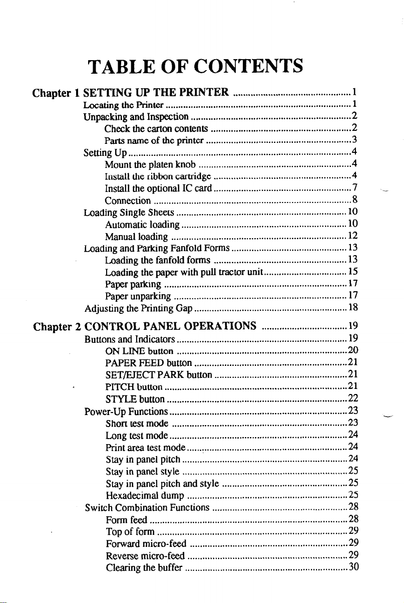
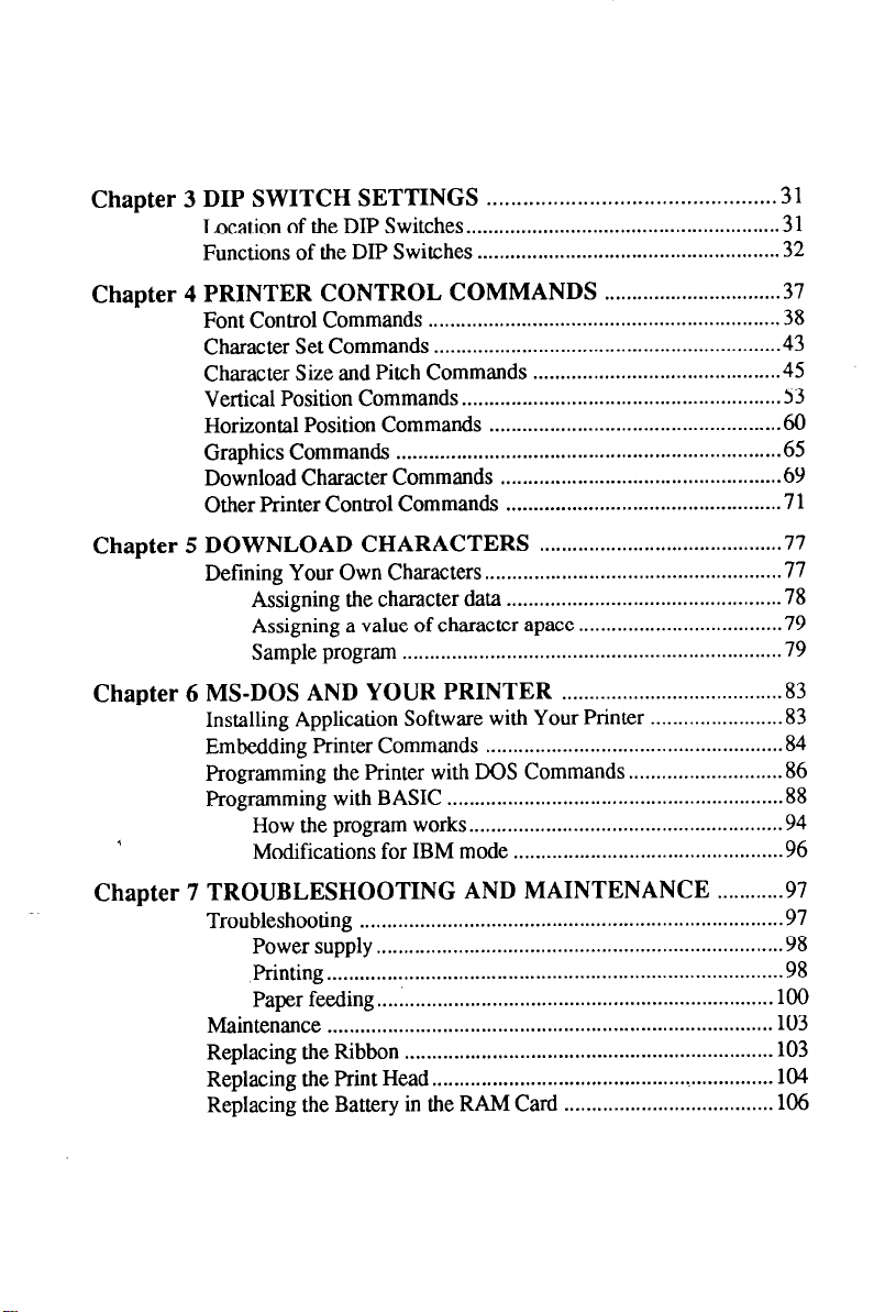
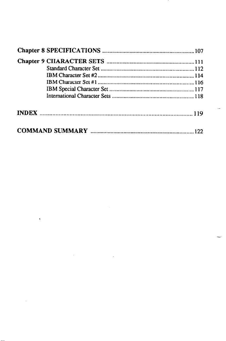

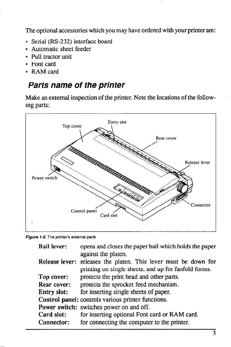
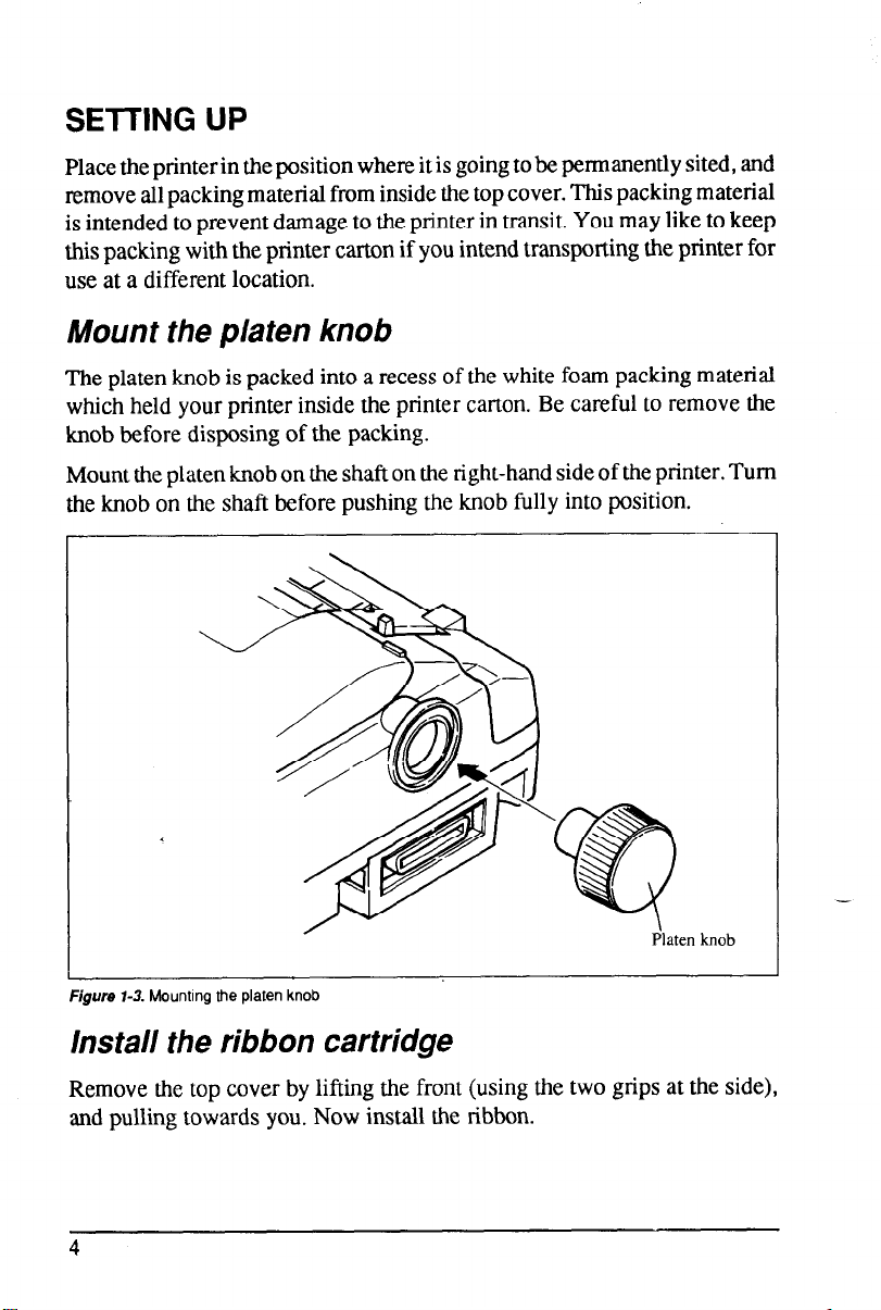
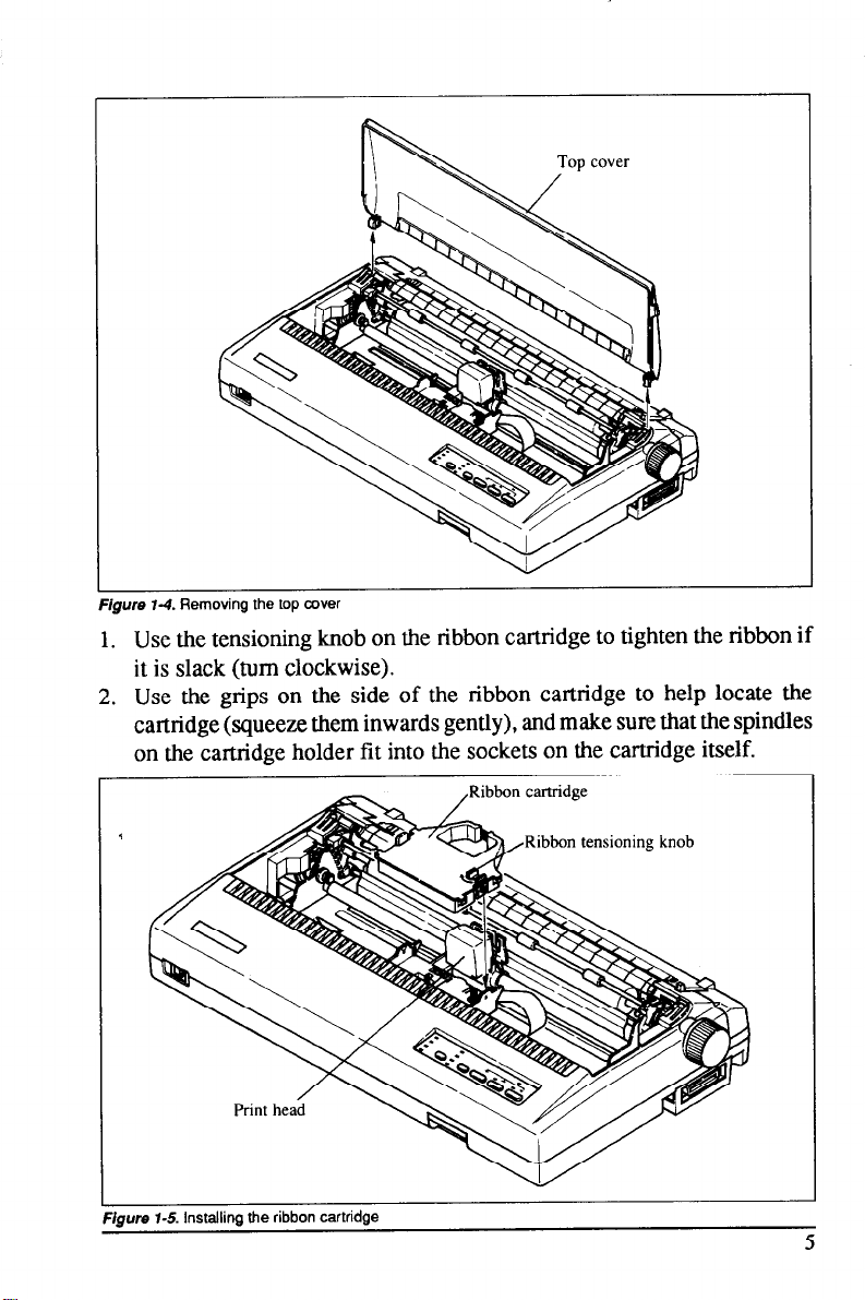
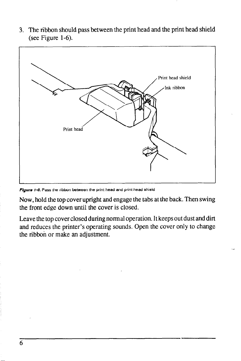
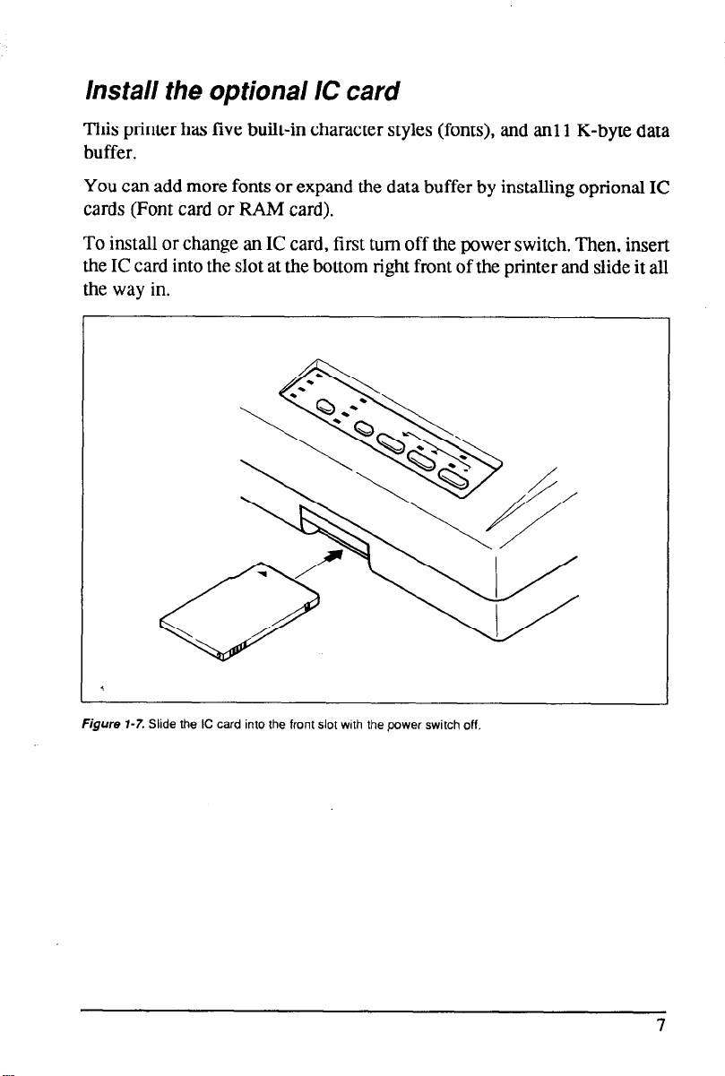
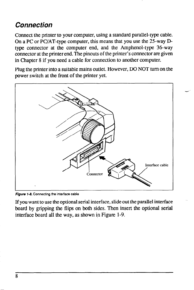
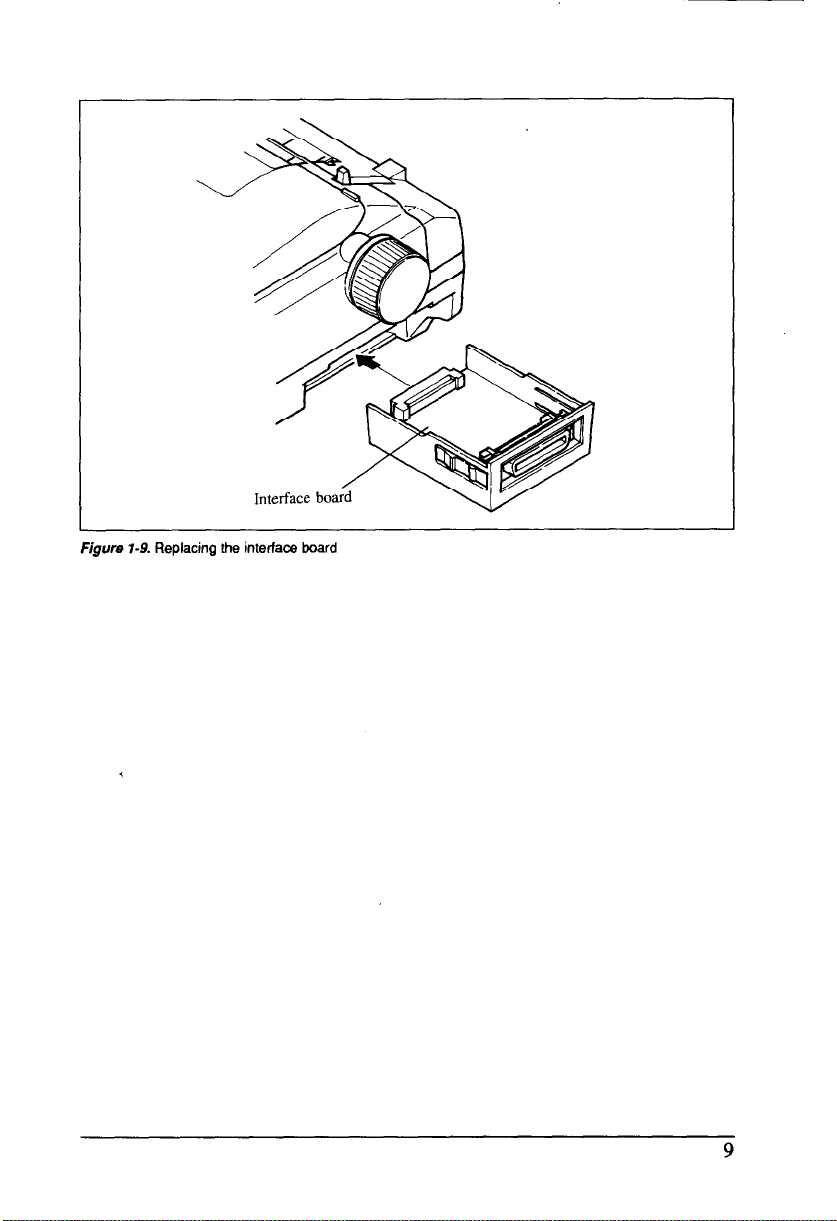
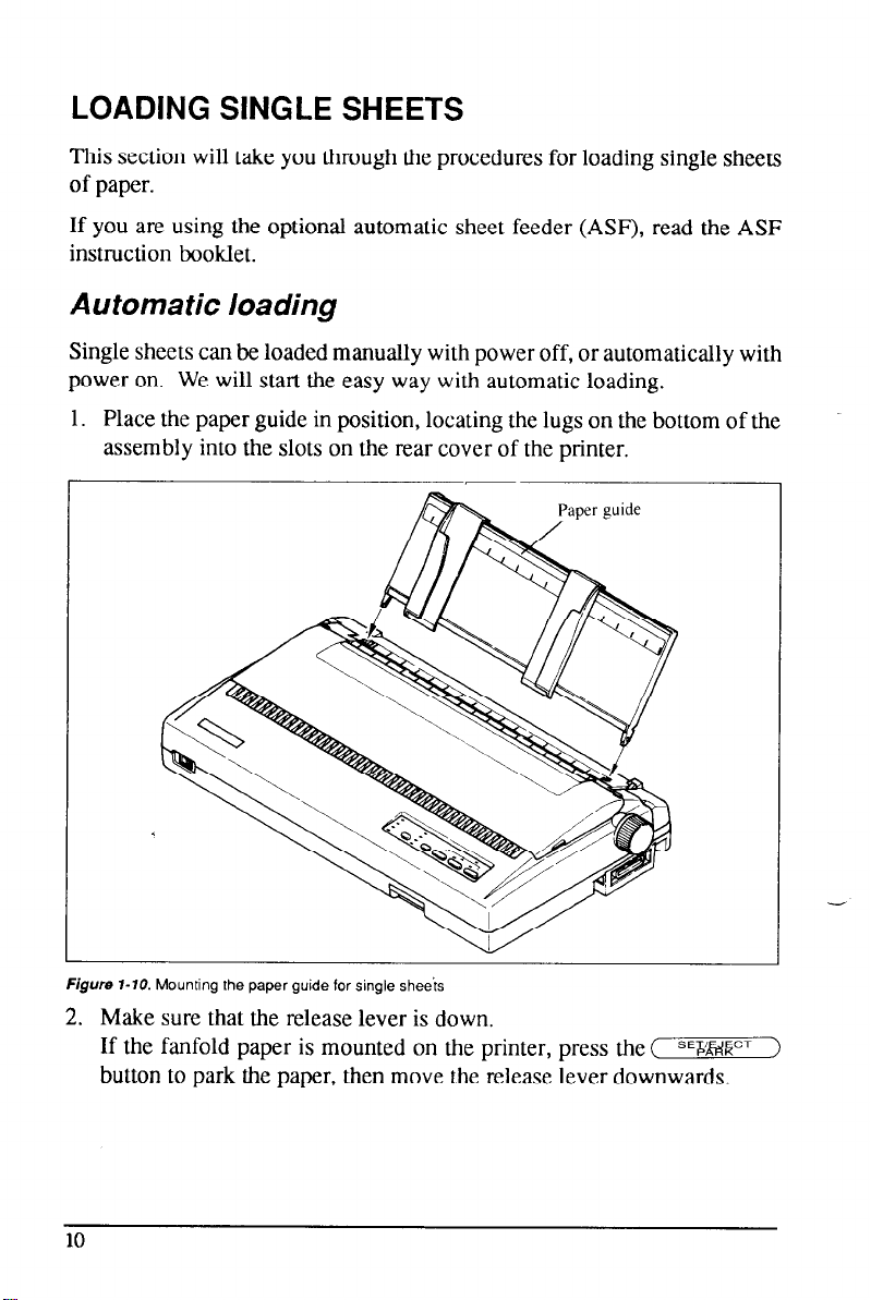
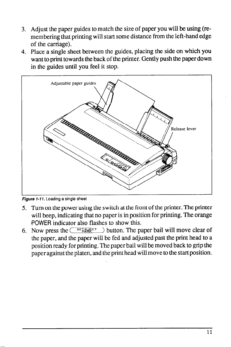
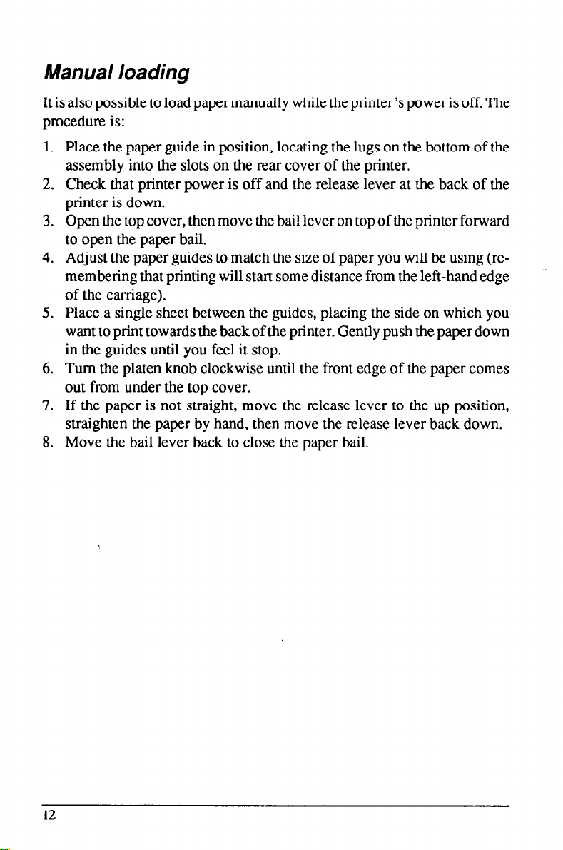

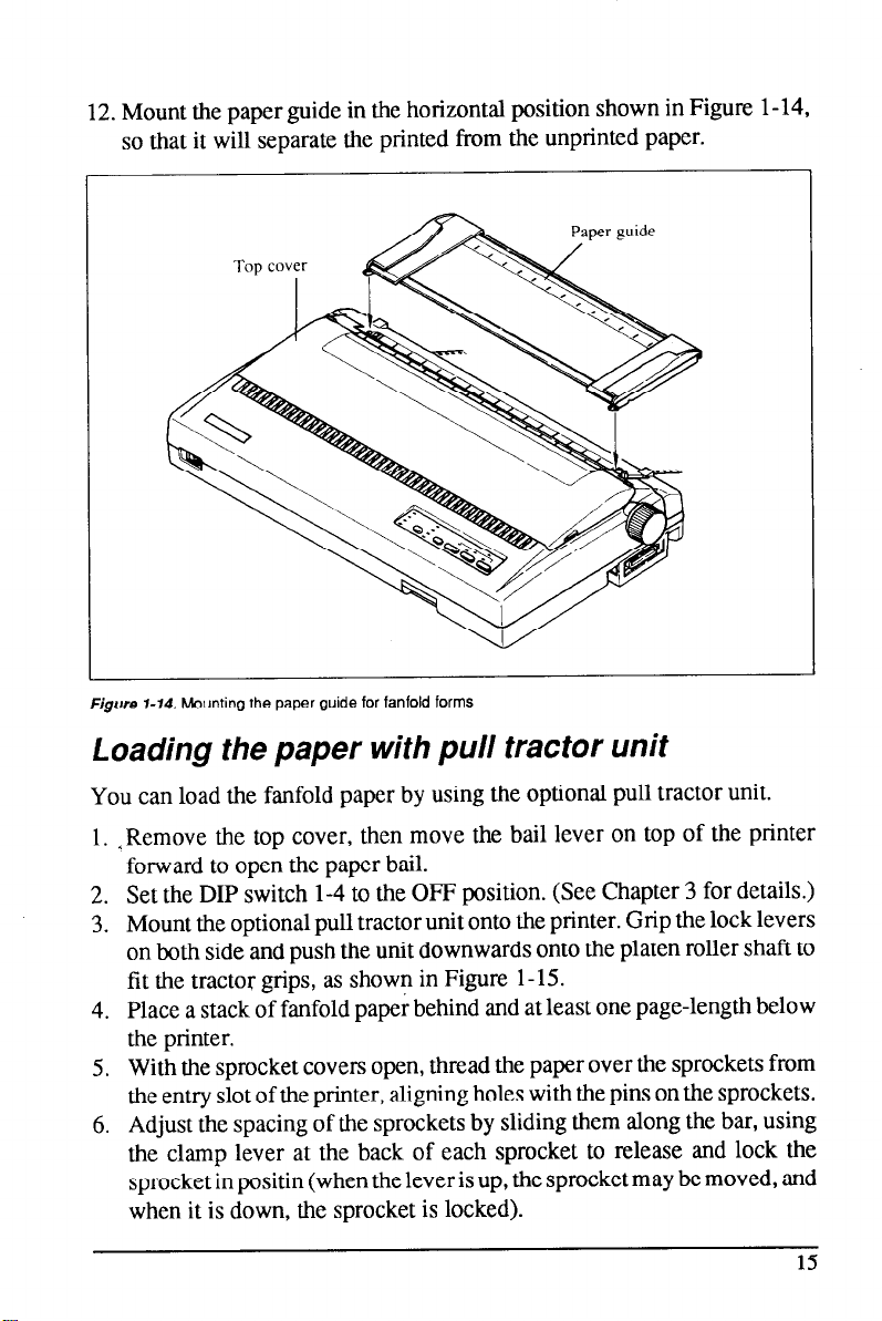
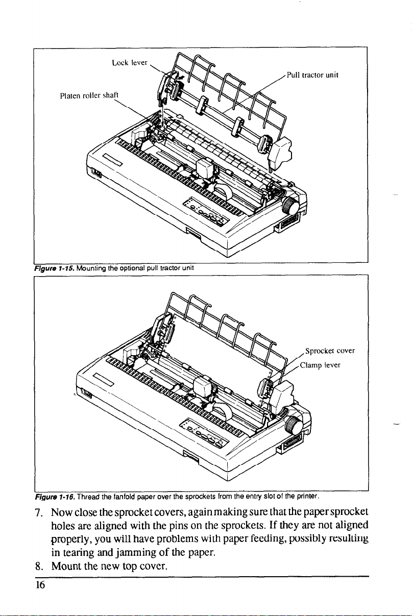
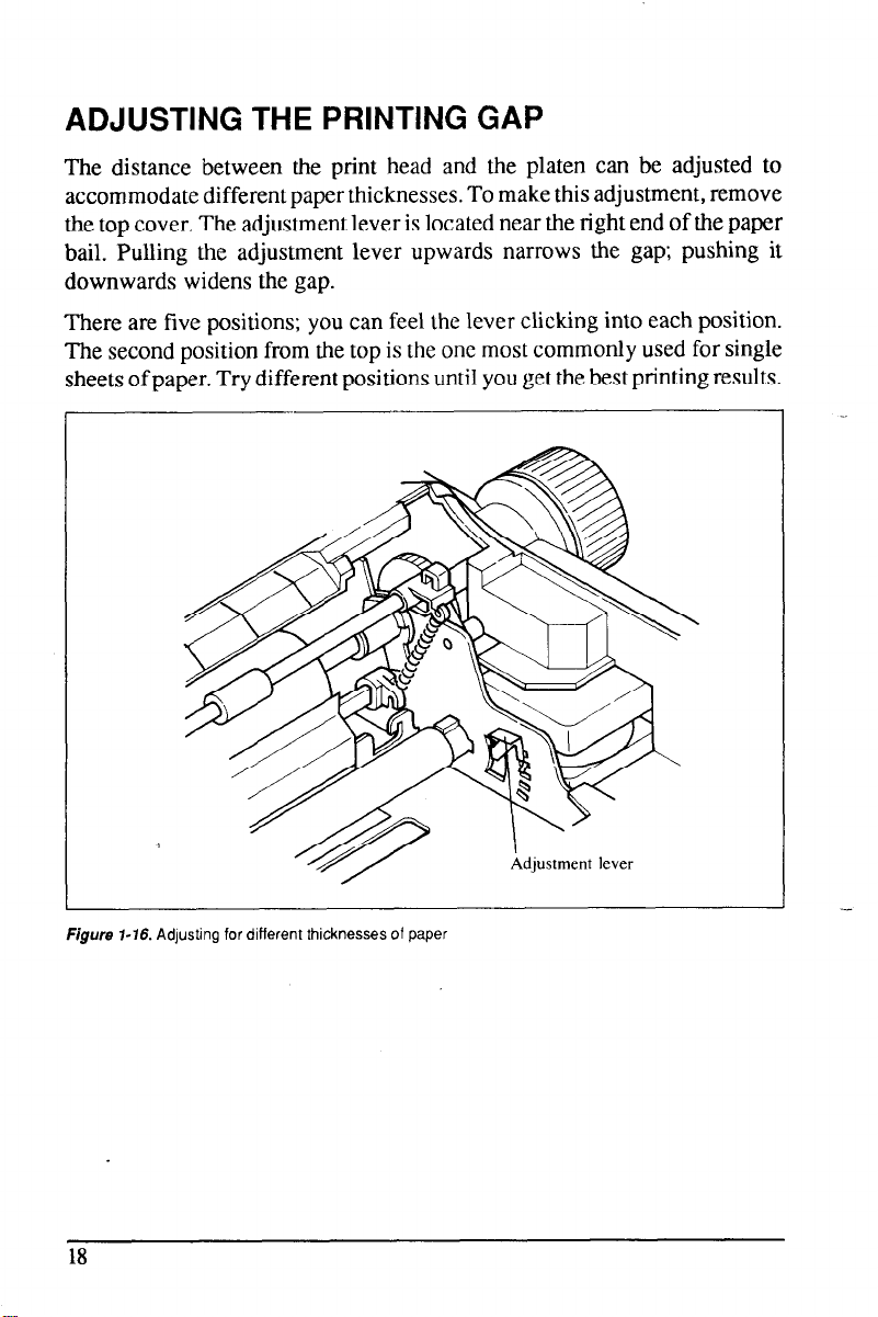
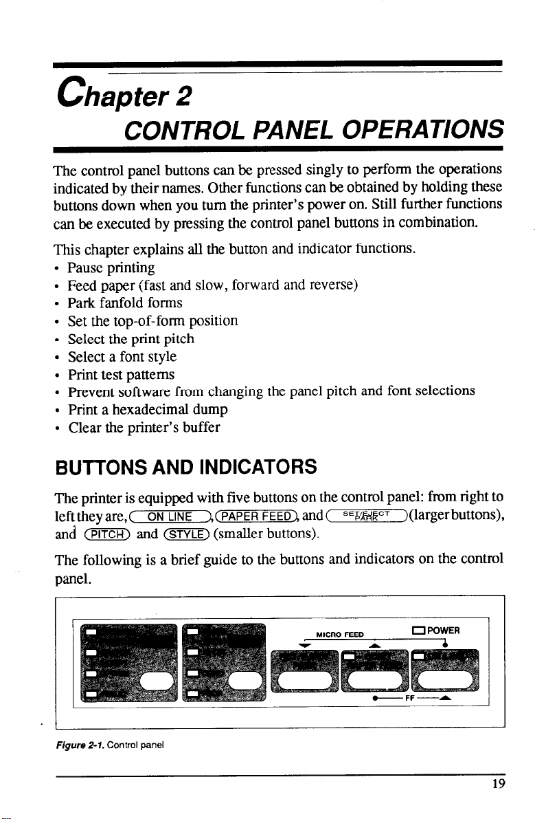
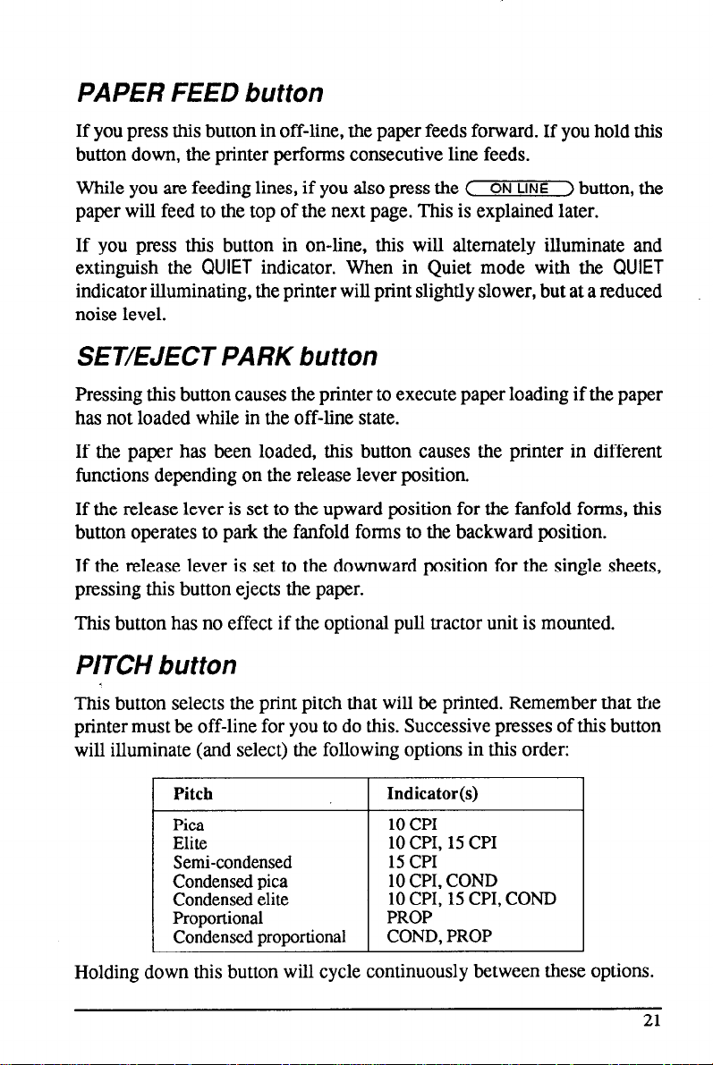


 Loading...