

Page 1

USER’S MANUAL
LC-1511
LC-1521
DOT MATRIX PRINTERS
HA15 80825072
Page 2

Federal Communications Commission
Radio Frequency Interference Statement
The 120V version equipment has been tested and found to comply with the limits for a Class B digital device, pursuant to Part 15 of FCC Rules. These limits are designed to provide reasonable protection against harmful interference
in a residential installation. This equipment generates, uses and can radiate radio frequency energy and, if not
installed and used in accordance with the instructions, may cause harmful interference to radio communications.
However, there is no guarantee that interference will not occur in a particular installation. If this equipment does
cause harmful interference to radio or television, which can be determined by turning off and on, the user is encouraged to try to correct the interference by one or more of the following measures.
• Reorient or relocate the receiving antenna.
• Increase the separation between the equipment and receiver.
• Connect the equipment into an outlet on a circuit different from that to which the receiver is connected.
• Consult the dealer or an experienced radio/TV technician for help.
Unauthorized modifications of this product by the user will void his authority to operate the equipment unless
expressly approved by the party responsible for compliance.
For compliance with the Federal Noise Interference Standard, this equipment requires a shielded cable.
The 220V version equipment has been tested and found to comply with the limits for a Class A digital device, pursu-
ant to Part 15 of the FCC Rules. These limits are designed to provide reasonable protection against harmful interference when the equipment is operated in a commercial environment. This equipment generates, uses, and can radiate
radio frequency energy and, if not installed and used in accordance with the instruction manual, may cause harmful
interference to radio communications.
Operation of this equipment in a residential area is likely to cause harmful interference in which case the user will be
required to correct the interference at his own expense.
For compliance with the Federal Noise Interference Standard, this equipment requires a shielded cable.
The above statement applies only to printers marketed in the U.S.A.
Statement of The Canadian Department of Communications Radio Interference
Regulations
This digital apparatus does not exceed the Class B limits for radio noise emissions from digital apparatus set out in
the Radio Interference Regulations of the Canadian Department of Communications.
Le présent appareil numérique n’émet pas de bruits radioélectiques dépassant les limites applicables aux appareils
numériques de la classe B prescrites dans le Règlement sur le brouillage radioélectrique édicté par le Ministère des
Communications du Canada.
The above statement applies only to printers marketed in Canada.
CE
Manufacturer's Declaration of Conformity
EC Council Directive 89/336/EEC of 3 May 1989
This product, has been designed and manufactured in accordance with the International Standards EN 50081-1/01.92
and EN 50082-1/01.92, following the provisions of the Electro Magnetic Compatibility Directive of the European
Communities as of May 1989.
EC Council Directive 73/23/EEC and 93/68/EEC of 22 July 1993
This product, has been designed and manufactured in accordance with the International Standards EN 60950, following the provisions of the Low Voltage Directive of the European Communities as of July 1993.
The above statement applies only to printers marketed in EU.
Ambient Noise Statement
Machine Noise Information Ordinance 3. GSGV, January 18, 1991: The sound pressure level at the operator position
is equal or less than 70 dB(A) according to ISO 7779.
The above statement applies only to printers marketed in EU.
Page 3

Trademark acknowledgments
FR-15, IS-8H192, IS-32H768, LC-1511, LC-1521, PT-15HA, SF-15HA, SPC-8K, XR-1500, XR-1520, ZA-250:
Star Micronics Co. Ltd.
EX-800, FX-1170: Seiko Epson Corporation
IBM PC, IBM Proprinter, IBM Proprinter2, IBM Proprinter 3, OS/2:
International Business Machines Corporation.
TrueType: Apple Computer Inc.
MS-DOS, Microsoft Windows, Windows 3.1, Windows 95: Microsoft Corporation
Notice
• All rights reserved. Reproduction of any part of this manual in any form whatsoever, without STAR’s express
permission, is strictly forbidden.
• The contents of this manual are subject to change without notice.
• All efforts have been made to ensure the accuracy of the contents of this manual at the time of printing. However, should any errors be found, STAR would greatly appreciate being informed of them.
• The above notwithstanding, STAR can assume no responsibility for any errors in this manual.
© Copyright 1995 Star Micronics Co., Ltd.
Page 4

About this manual
This manual describes how to set up, use, and care for the Star LC-1511 and
LC-1521 printers. The following is a list of what you can expect to find in each
chapter.
Chapter 1 Choosing a place for your printer, unpacking and setup,
Chapter 2 How to use the control panel
Chapter 3 How to use the printer’s Electronic DIP Switch (EDS)
Chapter 4 Installing, starting up and using the User Setup Utility
Chapter 5 How to set up for printing with Microsoft Windows 3.1,
Chapter 6 How to set up for printing with Microsoft Windows 95,
Chapter 7 How to set up for printing with IBM OS/2 Warp, how to
ribbon cassette installation, loading paper, connecting to
your computer
Mode to set up the printer to match the needs of your
system and software
how to prepare for printing, how to print a document
how to prepare for printing, how to print a document
prepare for printing, how to print a document
Chapter 8 How to set up for printing with MS-DOS
Chapter 9 Selecting the best type of paper, adjusting for paper
thickness, manual sheet feeding, clearing paper jams
Chapter 10 Optional accessories that are available for your printer
Appendix A How to deal with printing problems
Appendix B Specifications
Appendix C Interface information
Appendix D Character sets
Appendix E Printer control codes
Appendix F Glossary
Appendix G Control panel operation guide
Page 5

Contents
Chapter 1: Printer Setup ... 1
Choosing a place for the printer ... 1
Unpacking the printer ... 2
General guide ... 3
Opening the front cover ... 4
Removing the protective materials ... 4
Installing the platen knob ... 6
Installing the ribbon cassette ... 6
Removing the ribbon cassette ... 8
Installing the paper guide ... 9
Standing up the paper guide ... 10
Connecting to a power outlet and turning power on and off ... 11
Loading fanfold paper ... 12
Printing on fanfold paper ... 16
Parking fanfold paper ... 17
Unparking fanfold paper ... 17
Using the tear-off function ... 18
Connecting to your computer ... 18
Chapter 2: Control Panel Operations ... 20
Switching between on-line and off-line ... 20
Selecting a font ... 21
Entering the Font Lock Mode ... 21
Setting the character pitch ... 22
Entering the Pitch Lock Mode ... 22
Line feed ... 23
Paper eject (cut-sheet paper) ... 23
Form feed (fanfold paper) ... 23
Parking fanfold paper ... 23
Micro feed ... 23
Setting the top of form position ... 24
Tear-off function (fanfold paper) ... 24
Selecting the Quiet Print Mode ... 24
Changing the auto load position ... 25
Saving a macro ... 26
Clearing the printer’s buffer ... 26
Initializing the printer ... 27
Entering the Multi-part Mode ... 27
Page 6

Chapter 3: Using the EDS Mode ... 28
About EDS Mode settings ... 28
Entering the EDS Mode ... 28
Selecting a bank ... 29
Selecting a switch ... 29
Changing a switch setting ... 29
Printing the current switch settings ... 30
Checking the settings of switches in a bank ... 30
Exiting the EDS Mode ... 30
EDS Mode Settings ... 31
Chapter 4: User Setup Utility ... 40
Installing the User Setup Utility ... 40
Starting the User Setup Utility ... 41
Changing the General, Font, Paper and Adjust Settings ... 42
Adjusting the dot alignment ... 43
Changing the printer port ... 44
Saving setup data in a configuration file ... 44
Importing setup data from a configuration file ... 45
Returning to default settings ... 45
Exiting the User Setup Utility ... 45
Using the Help menu ... 45
Chapter 5: Using the Printer with Windows 3.1 ... 46
Setting up for printing with Microsoft Windows 3.1 ... 46
Getting ready to print ... 48
Printing a document ... 49
Installing TrueType fonts ... 50
Selecting fonts in Windows applications ... 51
Chapter 6: Using the printer with Windows 95 ... 52
Setting up the printer in Windows 95 ... 52
Preparing to print ... 55
Printing a document ... 57
Installing TrueType fonts ... 58
Chapter 7: Using the Printer with OS/2 Warp ... 59
Setting up for printing with OS/2 Warp ... 59
Getting ready to print ... 60
Printing a document ... 60
Page 7

Chapter 8: Using the Printer with MS-DOS ... 61
Setting up for printing with MS-DOS ... 61
Chapter 9: Paper Handling ... 62
Selecting paper types ... 62
Adjusting for paper thickness ... 63
Automatic fanfold feeding ... 64
Manual sheet feeding ... 64
Clearing paper jams ... 65
Chapter 10: Optional Accessories ... 66
Automatic Sheet Feeder (SF-15HA) ... 66
Pull Tractor Unit (PT-15HA) ... 67
Serial Interface Unit (IS-8H192 and IS-32H768) ... 67
Serial-to-Parallel Converter (SPC-8K) ... 69
Appendix A: Troubleshooting ... 70
Appendix B: Specifications ... 81
Appendix C: Interface Pin Outs ... 84
Appendix D: Character Sets ... 85
Appendix E: Printer Control Codes ... 95
Appendix F: Glossary ... 100
Appendix G: Control Panel Operation Guide ... 101
Page 8

Page 9

Chapter 1: Printer Setup
This chapter contains important information on setting up your printer. Be sure
to read this chapter carefully before using the printer for the first time. In this
chapter you will learn about:
❏ Choosing a place for the printer
❏ Unpacking and setting up the printer
❏ Installing the platen knob
❏ Installing the ribbon cassette
❏ Loading paper
❏ Connecting to your computer
Choosing a place for the printer
Before actually unpacking the printer, you should take a few minutes to think
about where you plan to use it. Remember the following points when doing this.
✓ Choose a firm, level surface where the printer will not be exposed to
vibration.
✓ The power outlet you plan to connect to for power should be nearby and
unobstructed.
✓ Make sure that the printer is close enough to your computer for you to
connect the two with your printer cable.
✓ Allow six inches (15 centimeters) of free space on either side of the printer .
If you are going to use fanfold paper, make sure that there is adequate space
for paper behind the printer.
✓ Make sure that the printer is not exposed to direct sunlight.
✓ Make sure that the printer is well away from heaters.
✓ Make sure that the surrounding area is clean, dry, and free of dust.
✓ Make sure that the printer is connected to a reliable power outlet. It should
not be on the same electric circuit as copiers, refrigerators, or other
appliances that cause power spikes.
✓ Use a power outlet that matches the power rating noted on the label affixed
to the bottom of your printer.
✓ Make sure that the room where you are using the printer is not too humid.
1
Page 10
2 Printer Setup
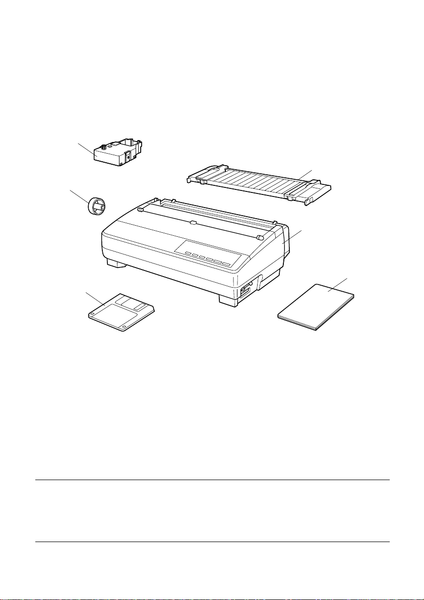
Unpacking the printer
Check to make sure that the carton contains each of the items shown in the
following illustration.
Ribbon cassette
Platen knob
3.5"Floppy disk
Paper guide
Printer
User’s manual
If anything is missing, contact the store where you bought the printer and ask
them to supply the missing part. Note that it is a good idea to keep the original
box and all the packing materials just in case you need to pack the printer up
again and send it somewhere at a later date.
A serial-to-parallel interface converter (SPC-8K), a serial interface unit (IS8H192 or IS-32H768), a pull tractor (PT-15HA), and an Automatic Sheet
Feeder (SF-15HA) are also available as options. Consult your dealer for details.
Important!
There are several versions of this printer designed for different voltages. It is
not possible to change the voltage of a printer. If the voltage shown on the label
on the bottom of your printer does not match the voltage for your ar ea, contact
your dealer immediately.
Page 11
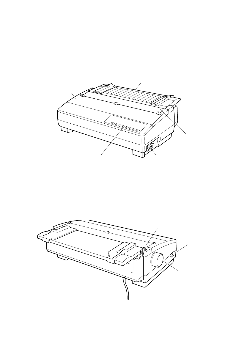
General guide
The following illustrations show the major components of your printer.
Front cover
General guide 3
Paper guide
Mute cover
Control panel
Interface connector
Release lever
Power switch
Platen knob
Page 12
4 Printer Setup
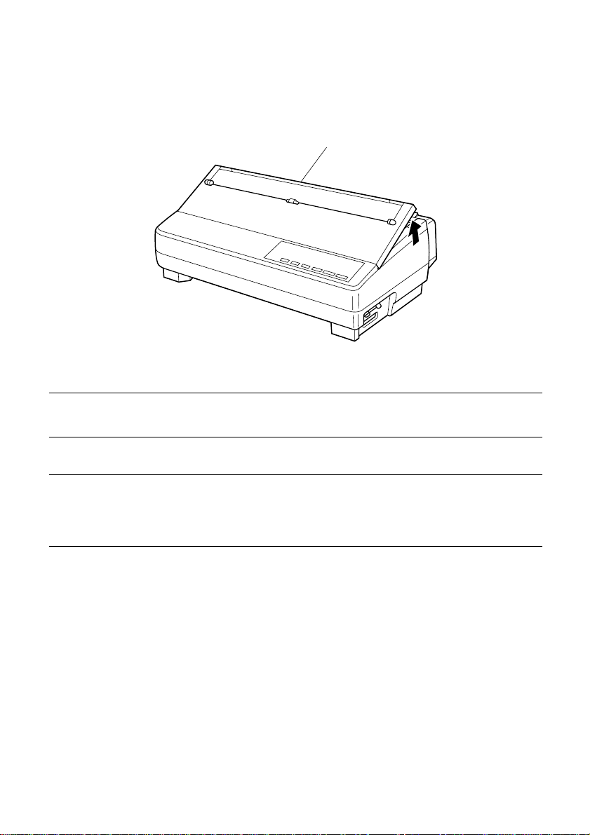
Opening the front cover
Lift up on the front cover and swing it open until it stops.
❏
❏ To close the front cover, simply lower it back into place.
Caution!
The tear assist edge is rather sharp. Take care to avoid injuring your hands.
Tear assist edge
Note:
You can completely remove the front cover from the printer or you can stand it
up. You should normally leave the front cover closed, because it protects
against objects getting into the printer, and it cuts down on printer noise.
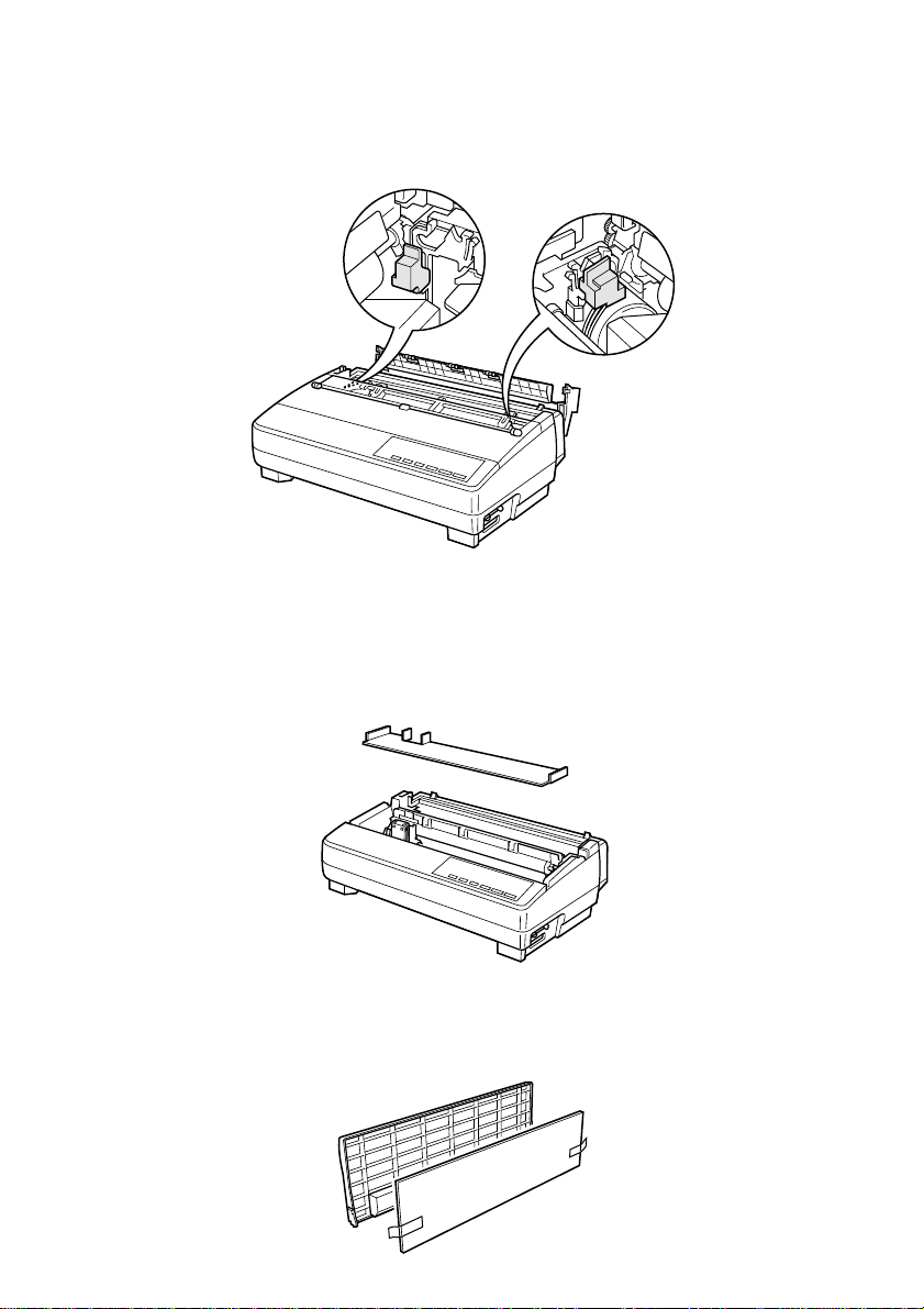
Removing the protective materials
Two small pieces of packing material are inserted into the printer to protect
components during shipping. Be sure to remove them before using the printer.
❏ Open the rear cover by pushing it back so that the cover swings back and
down.
Page 13
Removing the protective materials 5
❏ Remove the two white pieces of packing from inside the printer as shown in
the illustration.
A piece of cardboard is inserted into the printer to protect components during
shipping. Be sure to remove it before using the printer.
❏ Open the front cover.
❏ Remove the cardboard from the inside of the front cover as shown in the
illustration.
In addition, remove the cardboard from the back of the paper guide.
❏ Remove the tape.
❏ Remove the cardboard from the paper guide as shown in the illustration.
Page 14
6 Printer Setup
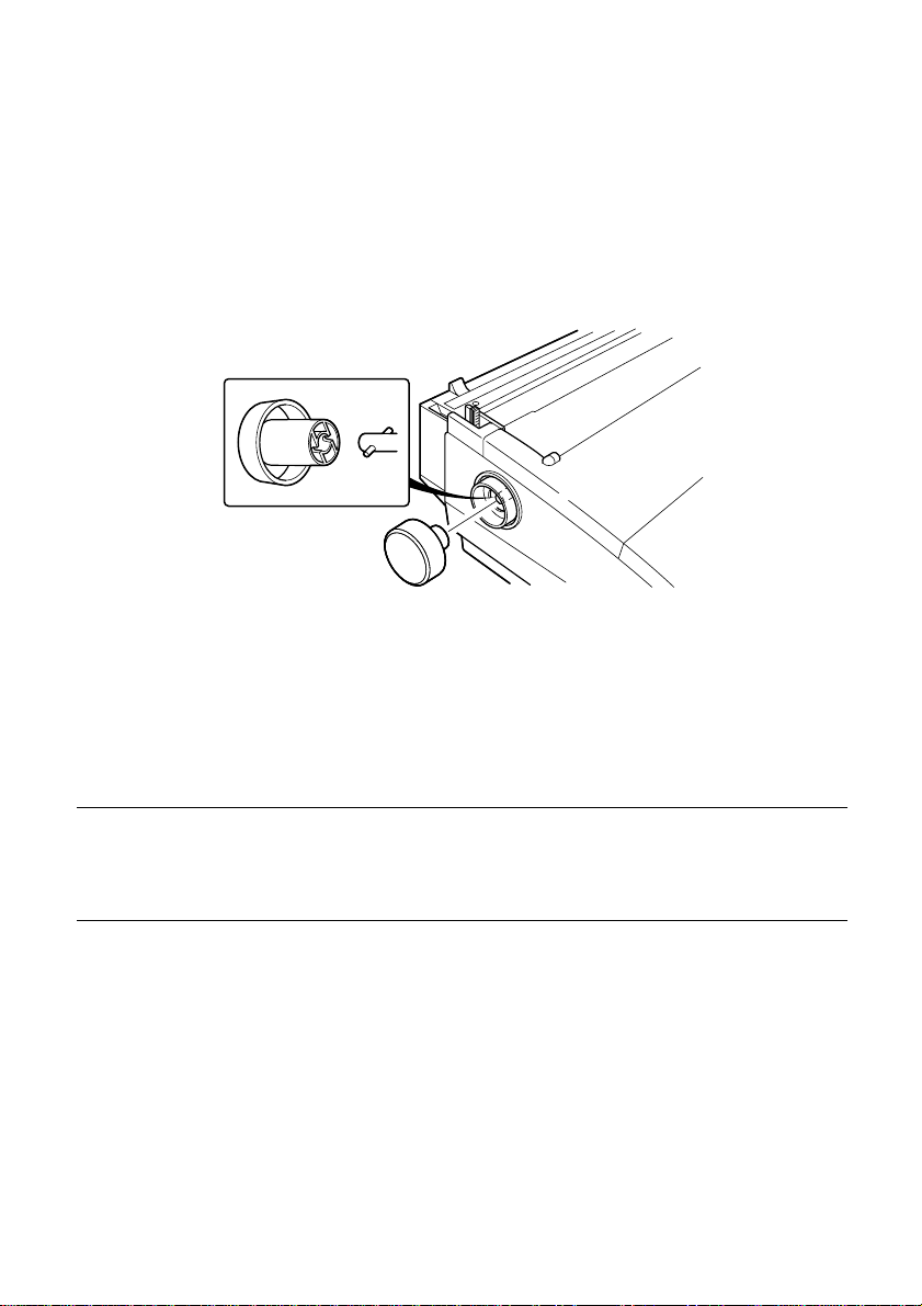
Installing the platen knob
The platen knob is packed into a recess in the packaging material.
❏ Install the knob on the shaft located inside the large hole on the left side of
the printer. Make sure that the two splines of the platen shaft inside the
printer fit into the slots inside the knob’s spindle. Press the knob carefully
but firmly into place as far as it will go.
Installing the ribbon cassette
Make sure the printer is unplugged from its power outlet.
❏
Caution!
Never move the print head while the printer is turned on. Doing so can damage
the printer. If you have just finished printing, let the print head cool for a few
minutes before you touch it.
❏ Remove the front cover of the printer.
❏ Remove the ribbon cassette from its package.
Page 15
Installing the ribbon cassette 7
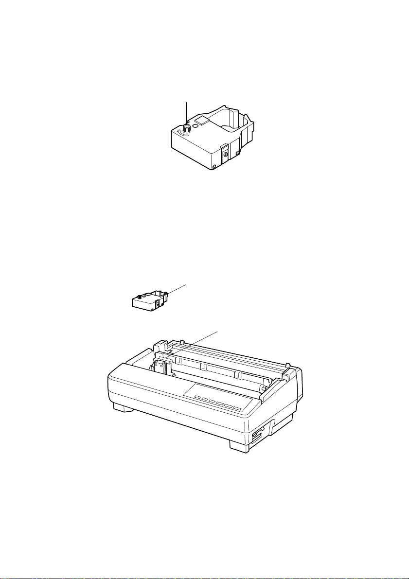
❏ Rotate the knob on the ribbon cassette clockwise to take up any slack in the
ribbon.
Tension knob
❏ By hand, move the cartridge holder to the left side where there is a cut-out
in the top guide to allow easy installation and removal of the ribbon
cassette.
❏ Carefully place the cassette onto the cartridge holder making sure that the
spindle of the holder fits into the socket on the bottom of the cassette. Also
make sure that the side tabs fit into the grooves on the sides of the cartridge
holder.
Ribbon cassette
Cut-out
Page 16
8 Printer Setup
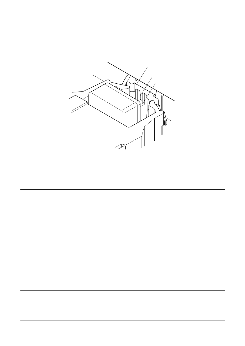
❏ While guiding the ribbon between the print head and print head shield,
press down gently but firmly on the cartridge until the side tabs snap
securely into place.
❏ Rotate the knob on the cassette again to take up any slack.
❏ Replace the front cover of the printer.
Print head shield
Ribbon
Print head
Important!
Printing that is poor quality or too light is almost always due to a ribbon that is
simply worn out or “used up.” If you experience problems with print quality,
check the condition of the ribbon. If the black part looks gray and well-worn,
replace the ribbon with a new one.
Removing the ribbon cassette
Use the following procedure to remove the ribbon cassette from the printer
when you want to replace it with a new one.
❏ Make sure that the printer is unplugged from its power outlet.
Caution!
Never move the print head while the printer is turned on. Doing so can damage
the printer. If you have just finished printing, let the print head cool for a few
minutes before you touch it.
Page 17
❏ Open the front cover of the printer.
❏ By hand, move the cartridge holder to the left side where there is a cutout in
the top guide to allow easy installation and removal of the ribbon cassette.
❏ Using your thumb and forefinger to squeeze the two tabs on the ribbon
cassette towards the center, carefully remove the cassette from the holder.
❏ Use the procedure under “Installing the ribbon cassette” on page 6 to install
a new cassette.
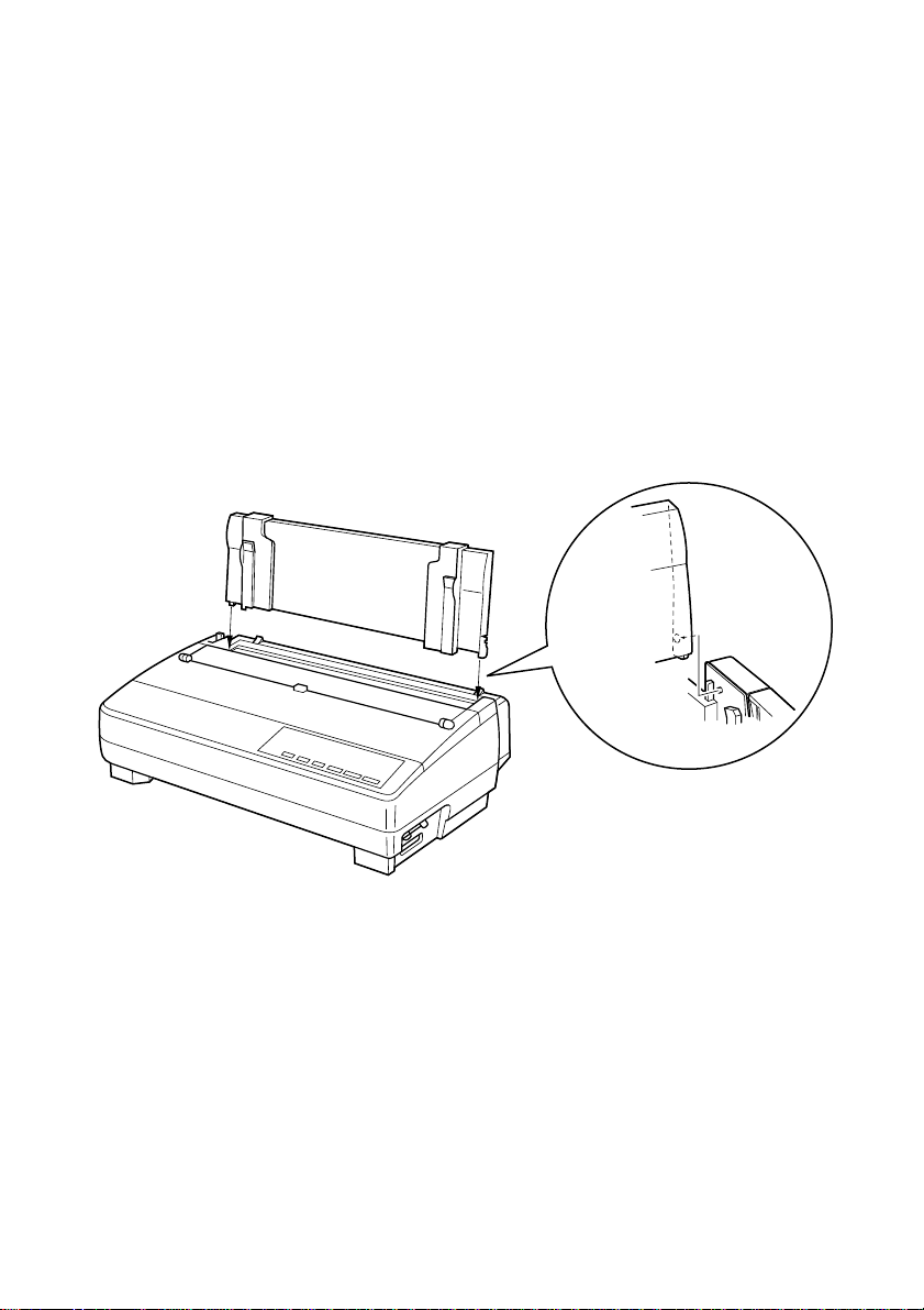
Installing the paper guide
Insert the two tabs on the rear cover of the printer into the holes in the
❏
bottom of the paper guide.
Installing the paper guide 9
❏ To remove the paper guide from the printer, simply pull the tabs out of the
holes.
Page 18
10 Printer Setup
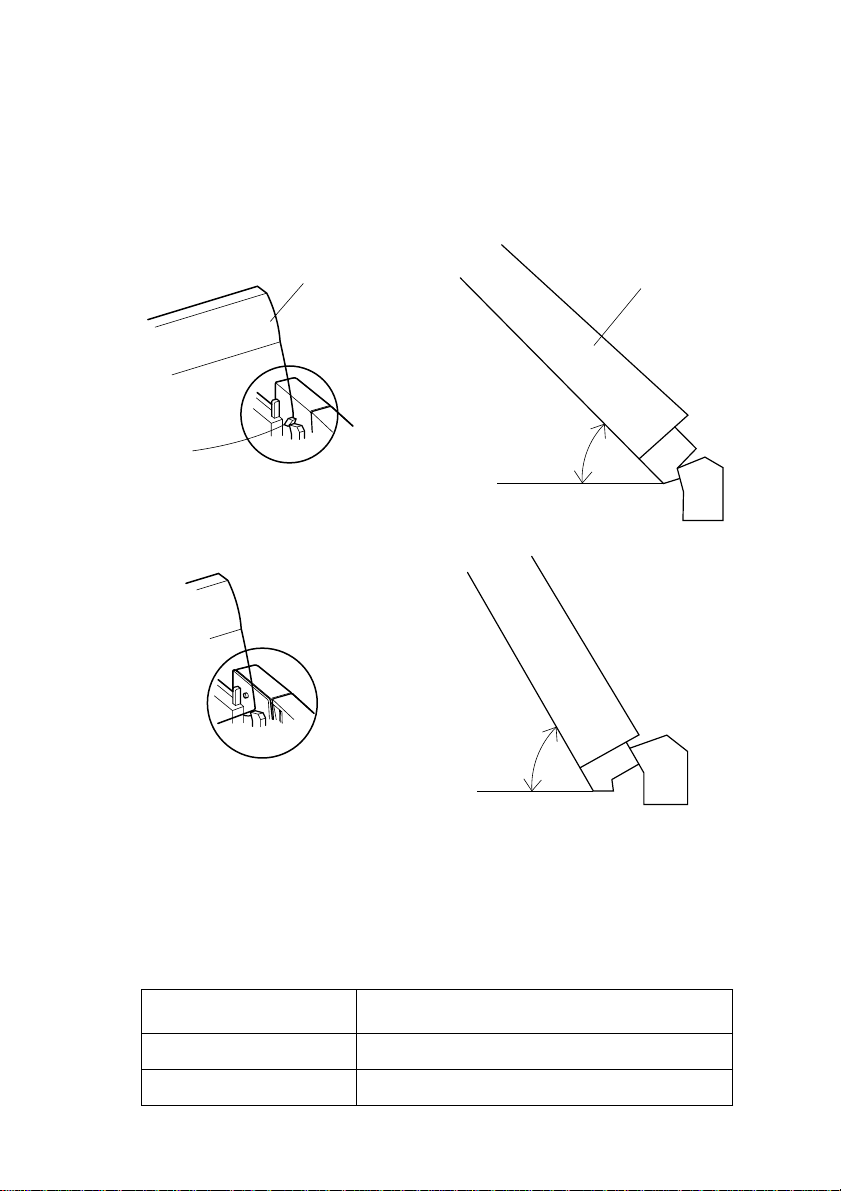
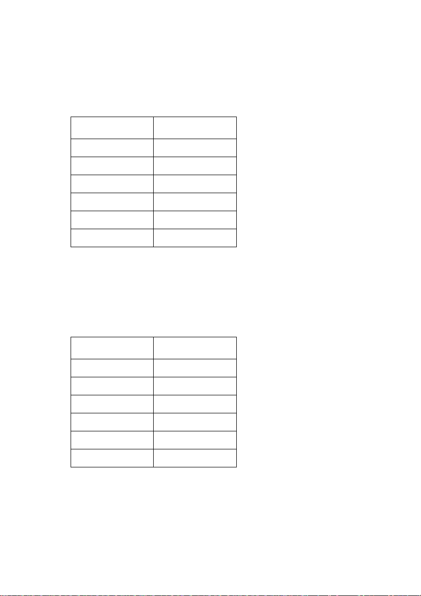
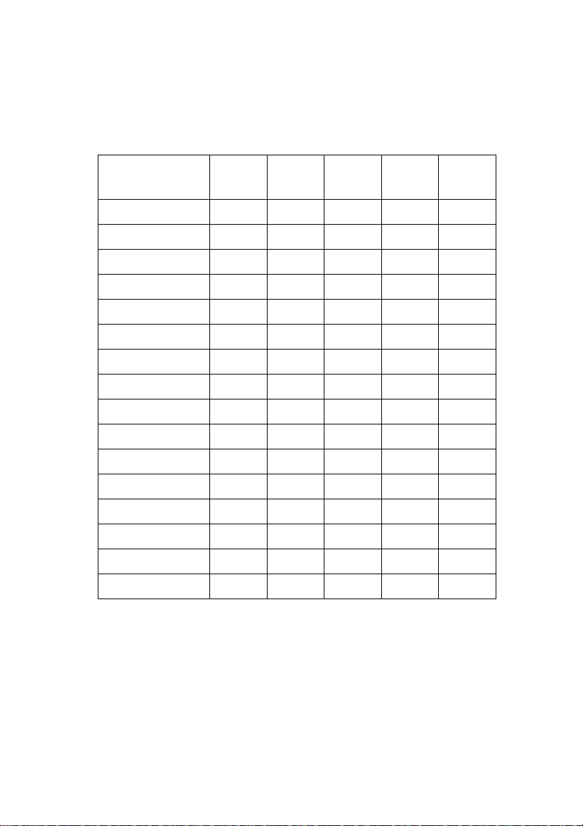
Standing up the paper guide
You can move the paper guide so that it is at angles of 50 or 70 as shown in
❏
the illustrations below. The correct angle depends on the type of the paper
you are using.
Paper guide
50-degree angle (Fanfold paper)
70-degree angle (Cut-sheet paper)
Paper guide
50°
70°
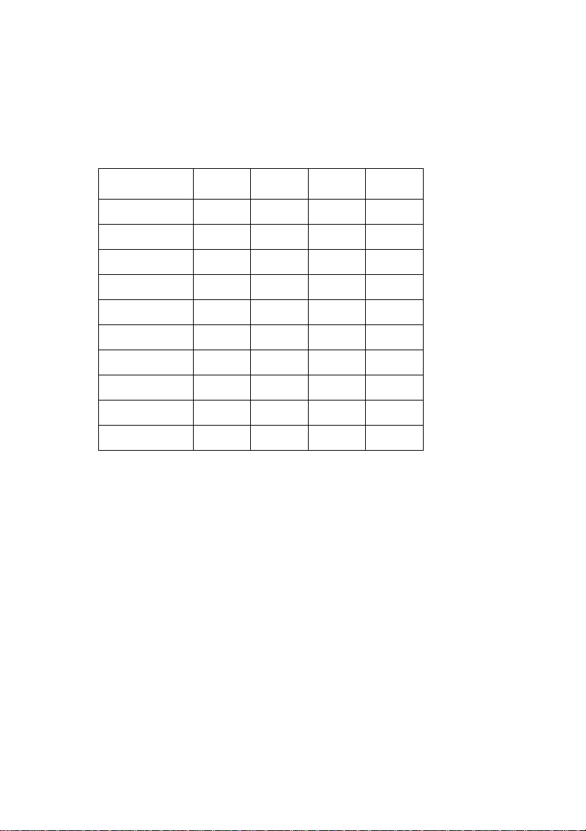
The following table shows the correct angle to use for each type.
Paper Type Paper Guide Angle
Fanfold 50 degrees
Cut-sheet 70 degrees
Page 19
Connecting to a power outlet and turning power on and off 11
Connecting to a power outlet and turning power on and off
Plug the power cord of the printer into a standard power outlet whose
❏
voltage matches the power rating noted on the label af fixed to the bottom of
your printer.
Caution!
If the voltage marked on the bottom of your printer does not match the voltage
from the outlet you are using, do not plug in the power cord. Contact your
dealer for assistance.
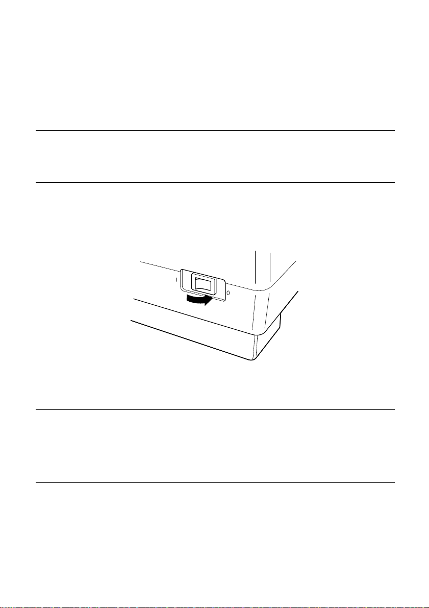
❏ Set the switch on the left of the printer to 1 (ON) to turn power on, and to 0
(OFF) to turn power off.
Caution!
Whenever you turn off the power, wait for at least five seconds before turning it
back on. Otherwise you may damage the printer. We also recommend that you
unplug the printer from the power outlet whenever you do not plan to use it for
long periods. Because of this, you should locate the printer so that the power
outlet it is plugged into is nearby and easy to access.
At this point you may want to perform a test of the printer to make sure it is
working properly. See “Testing the printer” on page 70 for details on how to
perform tests.
Page 20
12 Printer Setup
Loading fanfold paper
This section tells you how to load fanfold paper. Note that you can also use cutsheet paper. For details on using other types of paper, see “Paper Handling” on
page 62 of this manual.
❏ Remove the paper guide from the printer.
❏ Make sure printer power is turned off.
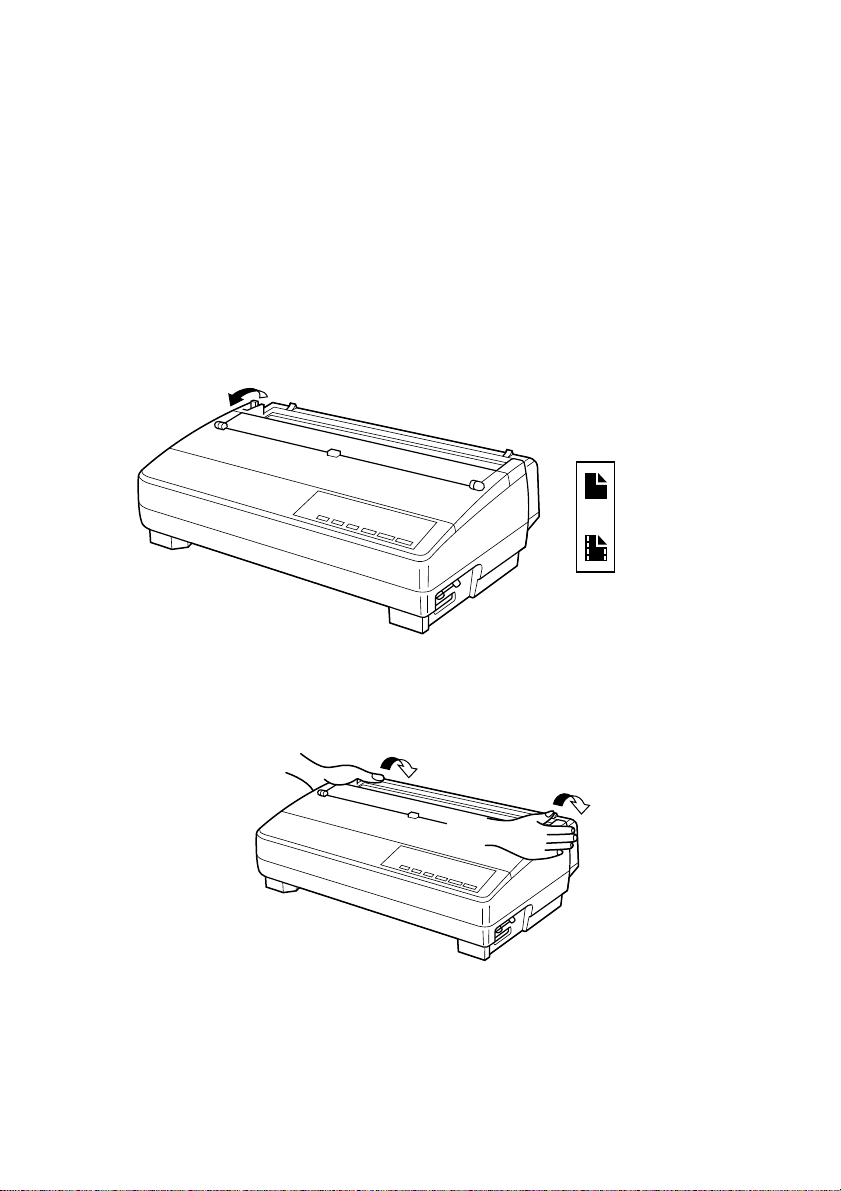
❏ Set the release lever to the fanfold position.
Cut-sheet
Fanfold
❏ Grasping the two back corners of the printer with the palms of your hands,
press back on the two raised areas on the top of the rear cover until it opens.
Page 21
Note:
Caution!
Loading fanfold paper 13
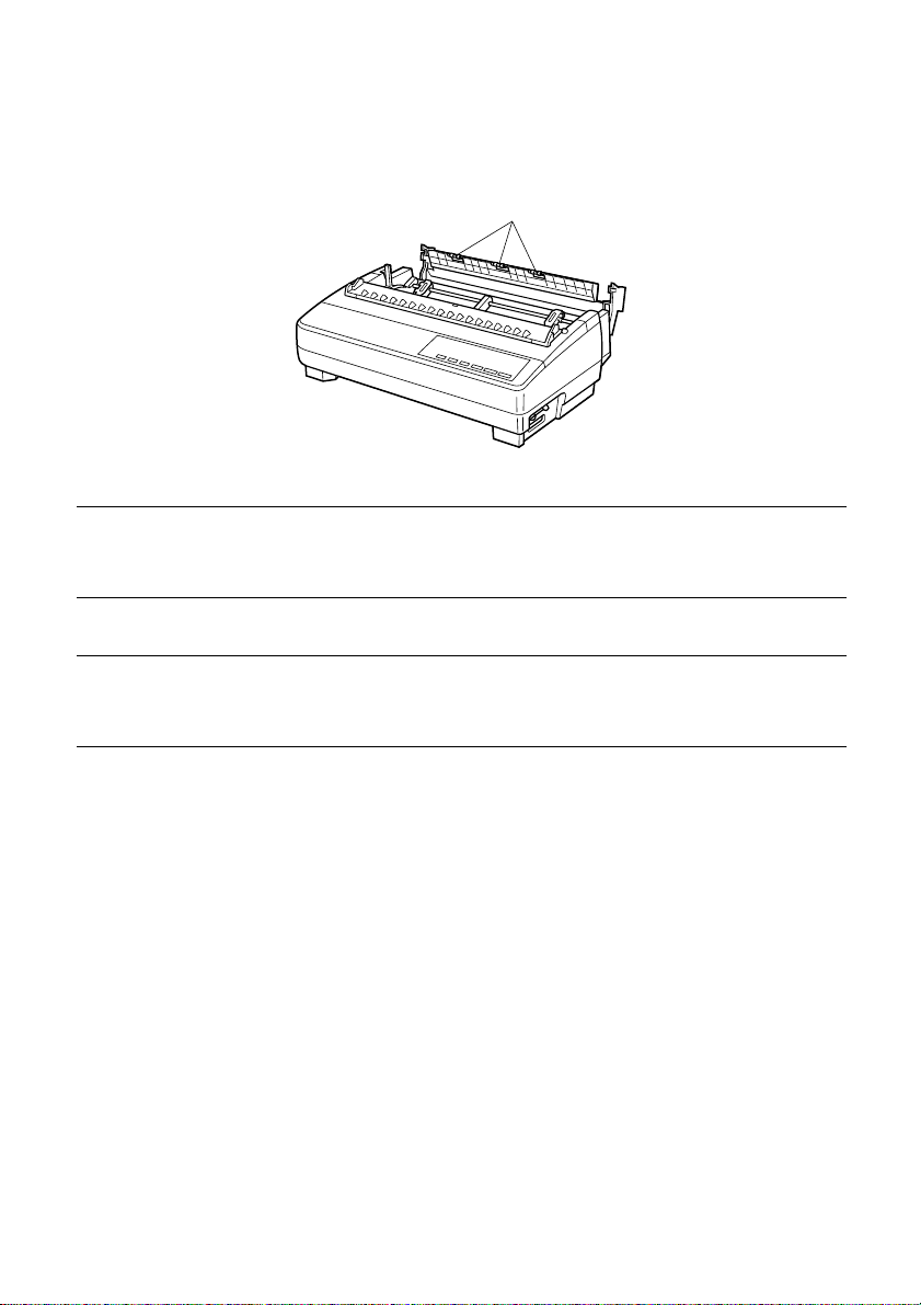
❏ Swing the rear cover back and down until it stops.
Metal edge
You can also completely remove the rear cover by simply pulling it away from
the back of the printer after you open it.
The metal edge of the cover is rather sharp. Take care to avoid injuring your
hands when handling it.
❏ Pass the fanfold paper through the space between the printer case and the
rear cover.
❏ Unlock the two tractor covers by pulling their gray levers up, and slide
them so they are aligned approximately with the holes on the sides of the
paper. Also move the center paper support so that it is approximately
halfway between the two tractors.
❏ Open the covers of both tractors and insert the paper so the tractor pins fit.
Page 22
14 Printer Setup
❏ Close the tractor covers. At this point you can make final adjustments to the
paper position by releasing the gray levers and moving the tractors. The
paper should lie flat with no buckling or bulging (tractors too close) or no
stretching or elongation of the holes (tractors too far apart). After making
these adjustments, be sure that you re-lock the tractors by pushing the gray
levers back into their original positions.
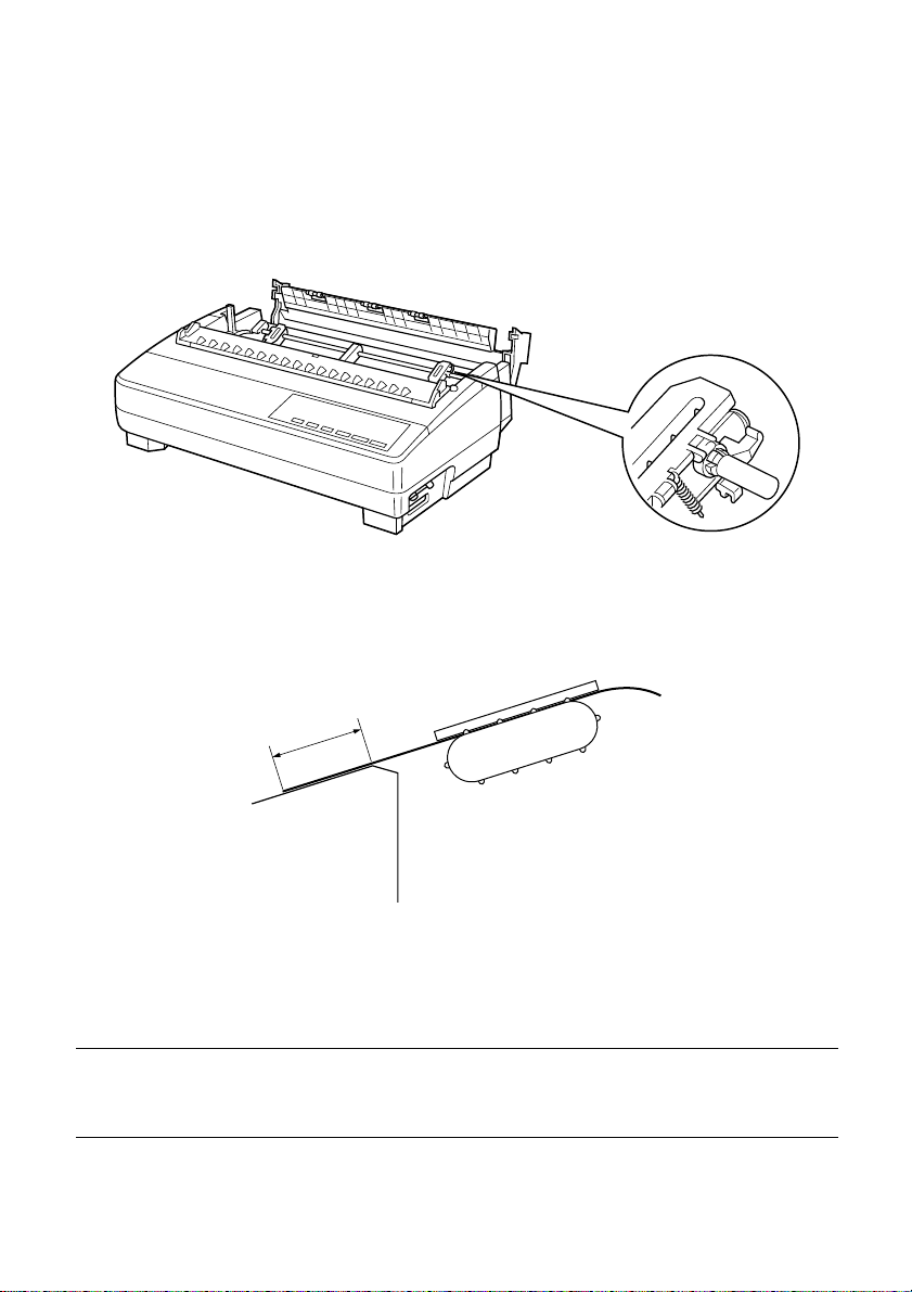
❏ Before printing, make sure that the leading edge of the fanfold paper
extends about 0.8 inch (two centimeters) past the front the paper chute, as
shown in the illustration below.
Caution!
0.8”(2cm)
❏ Close the rear cover and press down gently on it until it locks into place
with a click.
Since printing with an open rear cover may cause paper feeding problems, be
sure to close the rear cover before printing.
Page 23
Loading fanfold paper 15
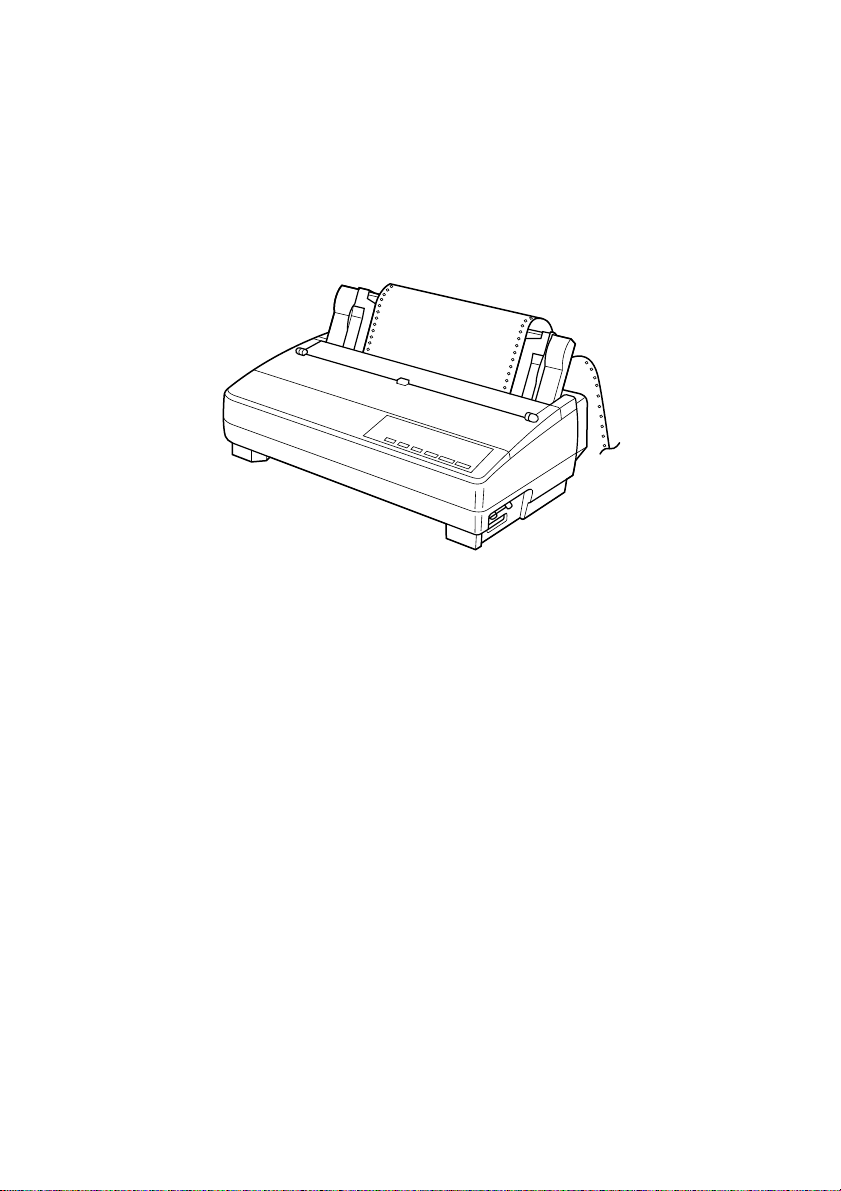
❏ Install the paper guide so that it is standing up (at a 50-degree angle) as
shown on page 10. In this position, the paper guide keeps the printed paper
separate from the unprinted paper.
Then slide the right and left paper guides apart so they do not interfere with
the fanfold paper feeding.
❏ Turn on the printer.
The printer will beep a number of times to indicate that paper is not loaded
properly. Also, the control panel’s POWER indicator flashes whenever
paper is not loaded.
❏ Press the SET/EJECT/PARK button to feed the paper to the starting
position.
Page 24
16 Printer Setup
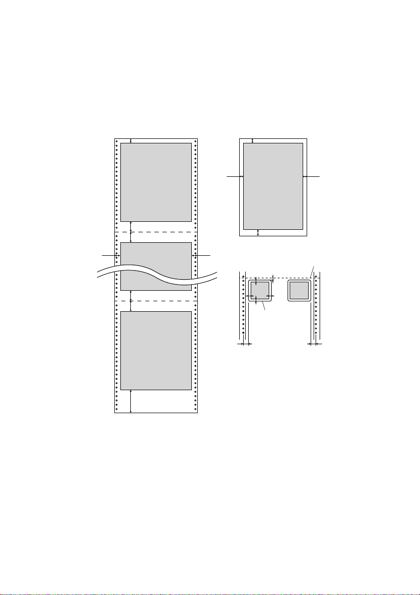
Printing on fanfold paper
When printing on fanfold paper, take care not to print too close to the
perforations that separate each sheet. The following shows the recommended
print area for fanfold paper, cut-sheet paper and label paper.
Perforation
18 mm
(0.7")
Perforation
Bottom of Form
Fanfold paper
4 mm (0.16")
25.4 mm (1")
25.4 mm (1")
25.4 mm (1")
25.4 mm (1")
110 mm (4.3")
First page
18 mm
(0.7")
Last page
5 mm
(0.2")
6.35 mm
(0.25")min.
Cut-sheet paper
4 mm (0.16")
8 mm (0.31")
Label
2.54 mm (0.1") min.
C
C
C
C
Label
C : 2.54 mm (0.1") min.
5 mm
Perforation
(0.2")
6.35 mm
(0.25")min.
Page 25

Parking fanfold paper
It is not necessary to remove fanfold paper currently loaded in the printer in
order to print on cut-sheet paper. Instead, simply use the following procedure to
park the fanfold paper.
❏ Tear off the paper at a perforation so there is no more than half a page
sticking out of the front cover of the printer.
If necessary, you can press the control panel’s ON LINE button to put the
printer off-line. and then use the LINE FEED button to feed the paper until
a perforation is just past the front cover.
❏ Press the control panel’s ON LINE button to put the printer off-line.
❏ Press the control panel’s SET/EJECT/PARK button. The printer
automatically reverse feeds the fanfold paper until it is no longer in contact
with the platen, which is indicated by the printer beeping a number of
times. Also, the control panel’s POWER indicator starts to flash because
paper is not loaded.
❏ Move the release lever to the cut-sheet position.
❏ Change the paper guide to its upright position.
You can now load cut-sheet paper into the printer using the procedures
under “Manual sheet feeding” on page 64.
Unparking fanfold paper
Parking fanfold paper 17
After you are finished printing on cut-sheet paper, use the following procedure
to unpark fanfold paper and make it available for printing.
❏ Remove all cut-sheet paper from the printer.
❏ Move the paper guide so that it is at a 50-degree angle. (Refer to page 10.)
❏ Move the release lever to the fanfold position.
❏ Press the SET/EJECT/PARK button to feed the paper to the starting
position.
The printer automatically goes back on-line at this time.
Page 26

18 Printer Setup
Using the tear-off function
The following procedure makes it easy to tear off fanfold paper.
❏ Check to make sure that the printer is on-line.
❏ Press the FORM FEED button to perform the long tear-off operation, or
press the LINE FEED button to perform the short tear-off operation.
The long tear-off operation causes the paper to be fed automatically so the
tear assist edge of the printer cover is aligned with the paper’s next
perforation.
The short tear-off operation causes the paper to be fed automatically so the
tear assist edge of the printer cover is located just below the last line printed
on the paper.
❏ Pull the paper against the tear assist edge to tear it off.
Connecting to your computer
The computer sends data to the printer through a cable. This printer does not
come with a cable, so you must purchase one separately. You will probably
want to use a standard parallel cable for connection, but note that you can also
use an optional serial-to-parallel interface converter (SPC-8K) or an optional
serial interface unit (IS-8H192 or IS-32H768).
Important!
The following instructions apply to the Centronics parallel cable that is used
with an IBM-compatible personal computer. Note that they do not apply to all
types of computers and cables. If you are unsure about what type of cable you
should use to connect with your computer, consult your dealer.
For an IBM-compatible personal computer:
✓ Use a standard 36-pin Centronics parallel cable.
✓ The parallel cable should be no longer than six feet (two meters). Longer
Important!
Make sure that the printer and the computer are turned off before connecting
them.
cables can result in poor transfer of information.
Page 27
Connecting to your computer 19
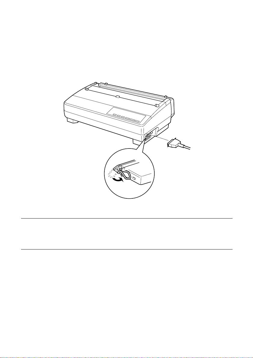
❏ Plug one end of the parallel cable into the parallel port of your computer.
The parallel port should be labeled “Printer,” “Parallel,” “PRN,” “LPT1,” or
something similar.
❏ Plug the other end of the parallel cable into the socket on the side of the
printer and secure it in place with the clips.
Note:
Consult your dealer for details on how to set up your computer when using the
optional SPC-8K serial-to-parallel interface converter or the IS-8H192 (or IS32H768) serial interface unit.
Page 28
20
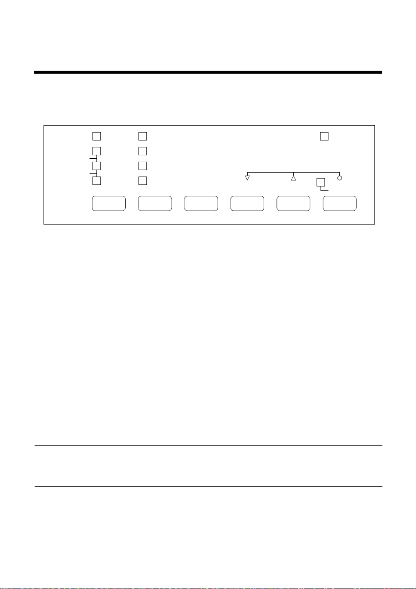
Chapter 2: Control Panel Operations
The control panel gives you push-button control over the printer’s operations. It
includes indicator lights, which tell you the current status of the printer at a
glance.
HS-DRAFT/DRAFT
ROMAN
SANSERIF
COURIER
PRESTIGE
ORATOR
EDS c BANK
BANK
A1
B2
C3
FONT
10 CPI
SW
D4
12 CPI
E5
COND
F6
PROP
PITCH
SWITCH
SET/EJECT
PARK
STATUS
This chapter describes control panel functions that can be performed while the
printer is turned on and either on-line or off-line. The buttons perform different
functions in the EDS and Dot Adjustment Modes. Functions of control panel
buttons in these modes are described in the relevant sections covering them.
Switching between on-line and off-line
Press ON LINE to switch the printer between being on-line and off-line.
❏
❏ When the printer is on-line, the ON LINE indicator is lit and the printer can
receive data from the computer. You should make sure that the printer is online whenever you are trying to print.
❏ When the printer is in off-line, the ON LINE indicator goes out, which
means that the printer cannot receive any data.
❏ Note that you can also press ON LINE while a printing operation is in
progress to stop the printing.
FORM FEED
ON/OFF
MICRO FEED
LINE FEED
PRINT
POWER
ON LINE
EXIT
Important!
Make sure that the on-line/off-line setting of the printer is correct before
performing a control panel operation.
Page 29
Selecting a font
Make sure the printer is off-line (ON LINE indicator is not lit).
❏
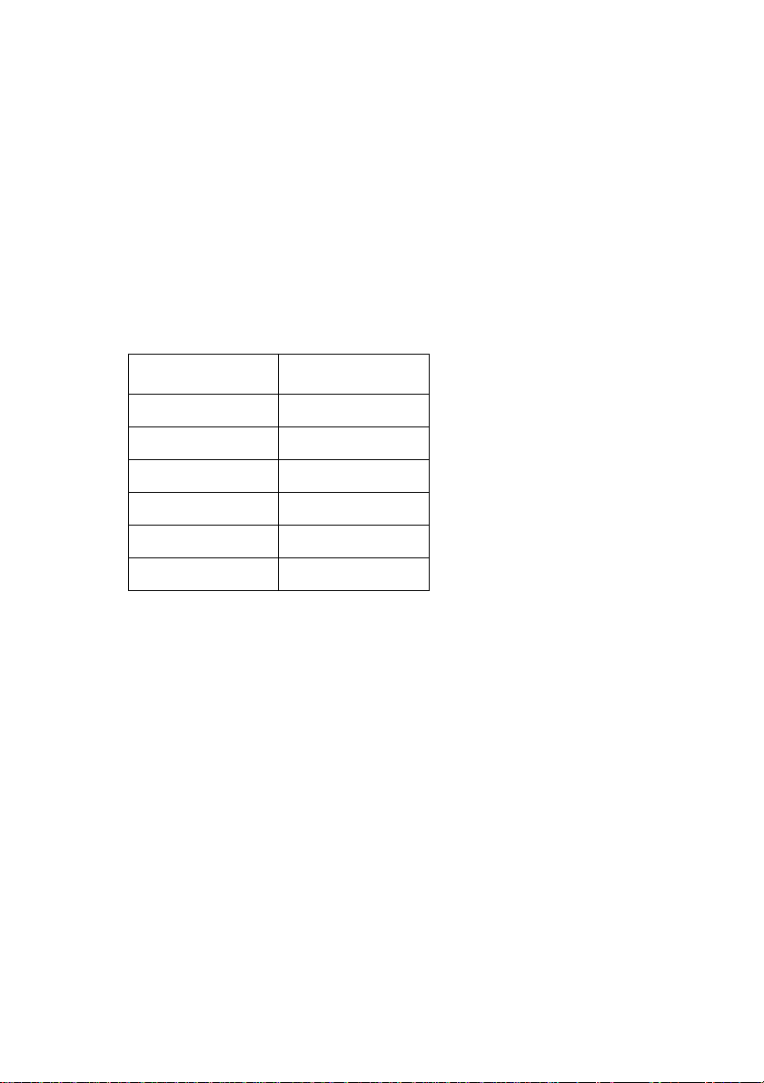
❏ Press FONT to change the font selection. An indicator lights to the left of
the name of the font that is currently selected. HS-Draft is selected when all
font indicators on the LC-1521 are off.
Lit Indicator Font
DRAFT Draft
ROMAN Roman
ROMAN + COURIER Sanserif
COURIER Courier
COURIER + ORATOR Prestige
ORATOR Orator
Note:
The font setting you make with the above procedure can be changed if the
software you are using overrides the setting on the control panel. You can
prevent this by using the following procedure to put the printer into the Font
Lock Mode when you turn it on.
Selecting a font 21
Entering the Font Lock Mode
When the printer is in the Font Lock Mode, the font settings you make on the
control panel are used even if your software tries to override the font. Use the
following procedure to enter the Font Lock Mode.
❏ Turn off the printer.
❏ While holding down FONT, turn printer power on.
The printer is now in the Font Lock Mode. You could enter the Font Lock
Mode and Pitch Lock Mode (page 22) at the same time by holding down
both FONT and PITCH when you turn on printer power.
To exit the Font Lock Mode, simply turn the printer off.
Important!
Font lock will not function if you are using Windows Truetype fonts.
Page 30
22 Control Panel Operations
Setting the character pitch
The character pitch setting controls how many characters are printed per inch.
Use the following procedure to select the pitch you want.
❏ Make sure the printer is off-line (ON LINE indicator is not lit).
❏ Press PITCH to change the pitch selection.
The following shows the meanings of the indicators that light on the control
panel when you press PITCH.
Lit Indicators Meaning
10CPI 10 characters per inch (Pica)
12CPI 12 characters per inch (Elite)
10CPI + COND 17 characters per inch (Condensed Pica)
12CPI + COND 20 characters per inch (Condensed Elite)
PROP Proportional
Note:
The pitch setting you make with the above procedure can be changed if the
software you are using overrides the setting from the control panel. You can
prevent this by using the following procedure to put the printer into the Pitch
Lock Mode when you turn it on.
Entering the Pitch Lock Mode
When the printer is in the Pitch Lock Mode, the pitch settings you make on the
control panel are used even if your software tries to override the pitch. Use the
following procedure to enter the Pitch Lock Mode.
❏ Turn off the printer.
❏ While holding down PITCH, turn printer power on.
The printer is now in the Pitch Lock Mode. You could enter the Pitch Lock
Mode and Font Lock Mode (page 21) at the same time by holding down both
FONT and PITCH when you turn on printer power.
To exit the Pitch Lock Mode, simply turn the printer off.
Important!
Pitch lock will not function if you are using Windows Truetype fonts.
Page 31

Line feed
Make sure the printer is off-line (ON LINE indicator is not lit).
❏
❏ Press LINE FEED once to feed paper one line. Holding down LINE FEED
continually feeds paper, one line at a time, until you release the button.
Paper eject (cut-sheet paper)
Make sure the printer is off-line (ON LINE indicator is not lit).
❏
❏ Press SET/EJECT/PARK to eject the paper.
❏ After the paper is ejected, the printer will beep and the POWER indicator
will flash to indicate there is no paper in the printer.
Form feed (fanfold paper)
Make sure the printer is off-line (ON LINE indicator is not lit).
❏
❏ Press FORM FEED and the printer will automatically feed the paper to the
top of the next page.
Line feed 23
Parking fanfold paper
Make sure the printer is off-line (ON LINE indicator is not lit).
❏
❏ Press the control panel’s SET/EJECT/PARK button.
❏ The printer automatically reverse feeds the fanfold paper until it is no
longer in contact with the platen.
Micro feed
Use the following operation to feed the paper in very small increments. This
makes it possible to align the print head exactly where you want it.
❏ Make sure the printer is off-line (ON LINE indicator is not lit).
❏ While holding down ON LINE, press LINE FEED to feed the paper
forward or FORM FEED to feed the paper backward.
Page 32

24 Control Panel Operations
Setting the top of form position
The current position of paper loaded in the printer is automatically set as the top
of the page whenever you turn power on. You can also use the following
procedure at any time to specify a different position as the top of the page.
❏ Make sure the printer is off-line (ON LINE indicator is not lit).
❏ Use the micro feed operations (see above) to move the paper so that the
print head is located where you want the new top of form position to be.
❏ While holding down FONT, press SET/EJECT/PARK.
The printer will beep once to indicate that a new top of form position has
been set.
Tear-off function (fanfold paper)
This procedure feeds fanfold paper to a position where it can be torn off easily.
❏ Check to make sure that the printer is on-line.
❏ Press the FORM FEED button to perform the long tear-off operation, or
press the LINE FEED button to perform the short tear-off operation.
The long tear-off operation causes the paper to be fed automatically so the
tear assist edge of the printer cover is aligned with the paper’s next
perforation.
The short tear-off operation causes the paper to be fed automatically so the
tear assist edge of the printer cover is located just below the last line printed
on the paper.
❏ Pull the paper against the tear assist edge to tear it off.
❏ When you resume printing, the printer reverse feeds the paper to its former
position.
Selecting the Quiet Print Mode
The Quiet Print Mode lets you print with less noise than that produced with
normal printing. Use the following procedure to enter and exit the Quiet Print
Mode.
Important!
Though the Quiet Print Mode prints more quietly, it also causes printing to
take considerably longer than normal printing.
Page 33

❏ Make sure the printer is on-line (ON LINE indicator is lit).
❏ Press SET/EJECT/PARK, to toggle between the Quiet Print Mode and
normal printing.
The printer emits one short beeps when the Quiet Print Mode is selected, and
two short beep when normal printing is selected.
Changing the auto load position
Normally the printer automatically feeds paper to a standard position (1/6-inch
from the top of the paper). This is called the auto load position. You can use the
following procedure to specify a different auto load position.
❏ Make sure the printer is off-line (ON LINE indicator is not lit).
❏ While holding down ON LINE, press SET/EJECT/PARK and then
release the two buttons.
The printer will automatically eject the cut-sheet that is in the printer, or
reverse feed fanfold paper until it is no longer in contact with the platen.
Also, all the font and pitch indicators on the control panel will light.
❏ Press SET/EJECT/PARK to feed the paper to the starting position.
❏ Feed the paper so the print head is located where you want the new auto
load position to be.
Press LINE FEED to feed the paper forward and FORM FEED to feed the
paper backward. This is the micro feed operation.
❏ After you have the paper at the position you want, hold down ON LINE
and press LINE FEED to make the current print head position the new auto
load position. The printer will beep twice to indicate that the new auto load
position is set.
❏ To clear the new auto load position and return to the one that you set
previously (using the above procedure), press ON LINE. To clear the
currently set auto load position and return to the standard position (1/6-inch
from the top of the paper), hold down ON LINE and press SET/EJECT/
PARK.
Changing the auto load position 25
Note:
The auto load position you set remains in effect until you turn the printer of f . If
you want to save the auto load position in memory, pr ess FORM FEED instead
of LINE FEED while holding down ON LINE in the above step.
Page 34

26 Control Panel Operations
Saving a macro
Normally, any settings you make on the control panel are cleared when you turn
the printer off. Use the following procedure to save the current control panel
settings so that they are used whenever you turn the printer on.
❏ Make the control panel settings you want.
❏ Use ON LINE to put the printer off-line (ON LINE indicator is not lit).
❏ Hold down FONT and then PITCH. Keep both b uttons held do wn until the
printer beeps twice.
Pressing FONT normally changes the font setting, so when you press it in
the above step the indicator for the next font lights. Pressing PITCH,
however, returns the font setting to what it was before you pressed FONT.
This procedure saves the following settings.
• Current font and pitch settings
• Quiet Print Mode status
These items can be set separately for the Standard mode and the IBM mode.
❏ To clear saved control panel settings repeat the above procedure, but keep
FONT and PITCH depressed after the printer beeps twice. Soon the printer
will beep again three times to indicate that the saved control panel settings
have been cleared.
Clearing the printer’s buffer
When the printer receives data from a computer, it temporarily stores it in a
memory called a buffer. If you stop a printing job partway through, there is the
chance that some data will remain in the buffer. The following procedure clears
the printer’s buffer by deleting any data that might be there.
❏ Execute the necessary command in the program you are using to stop the
print job.
Important!
Be sure to stop the print job before taking the printer off line. Otherwise, the
print job will resume from where you interrupted it when you put the printer
back on-line.
❏ Use ON LINE to take the printer off line (ON LINE indicator is not lit).
❏ Hold down FONT and then FORM FEED. Keep both buttons held down
until the printer beeps once, which indicates that the buffer is cleared.
Page 35

Initializing the printer
The following procedure initializes the printer to its power-on settings. If you
have control panel settings stored in memory, this procedure sets up the printer
using them.
❏ Use ON LINE to take the printer off line (ON LINE indicator is not lit).
❏ Hold down FONT and then FORM FEED. Keep both buttons held down
until the printer beeps once (indicating the printer buffer is cleared) and
then beeps again three times, which indicates that the printer is reset.
Entering the Multi-part Mode
When the printer is in the Multi-part Mode, the print head prints with greater
impact. It should be noted, however, that printing in the Multi-part Mode also
reduces the life of the print head. Because of this, you should use the Multi-part
Mode only for printing on four or five-ply paper. Return to the normal mode for
printing on one to three-ply paper.
Use the following procedure to enter the Multi-part Mode
❏ Turn off the printer.
❏ While holding down the control panel’s SET/EJECT/PARK button, turn
the printer back on.
❏ To exit the Multi-part Mode, Simply turn the printer off and back on again.
27
Page 36
28
Chapter 3: Using the EDS Mode
The letters “EDS” stand for “Electronic DIP Switches.” Just like the small DIP
switches that are used by many computers, printers, and other devices, the EDS
mode lets you configure the printer so that it matches your system and software
needs. This chapter describes how to enter the printer’s EDS Mode and provides
details about available settings and how to change them.
All switch settings, except for F-2, are ON when the printer is shipped from the
factory.
About EDS Mode settings
EDS Mode settings are grouped among six “banks” (representing banks of
switches) that are identified by the letters A through F. Each bank contains a
number of “switches” numbered 1 through 6 that you can turn on and off to
configure the printer.
Entering the EDS Mode
Make sure that paper is loaded in the printer.
❏
❏ Turn off the printer.
❏ While holding down the control panel’s ON LINE, LINE FEED, and
FORM FEED buttons, turn the printer back on.
This causes the following message to be printed, which indicates the printer
is in the EDS Mode.
Page 37
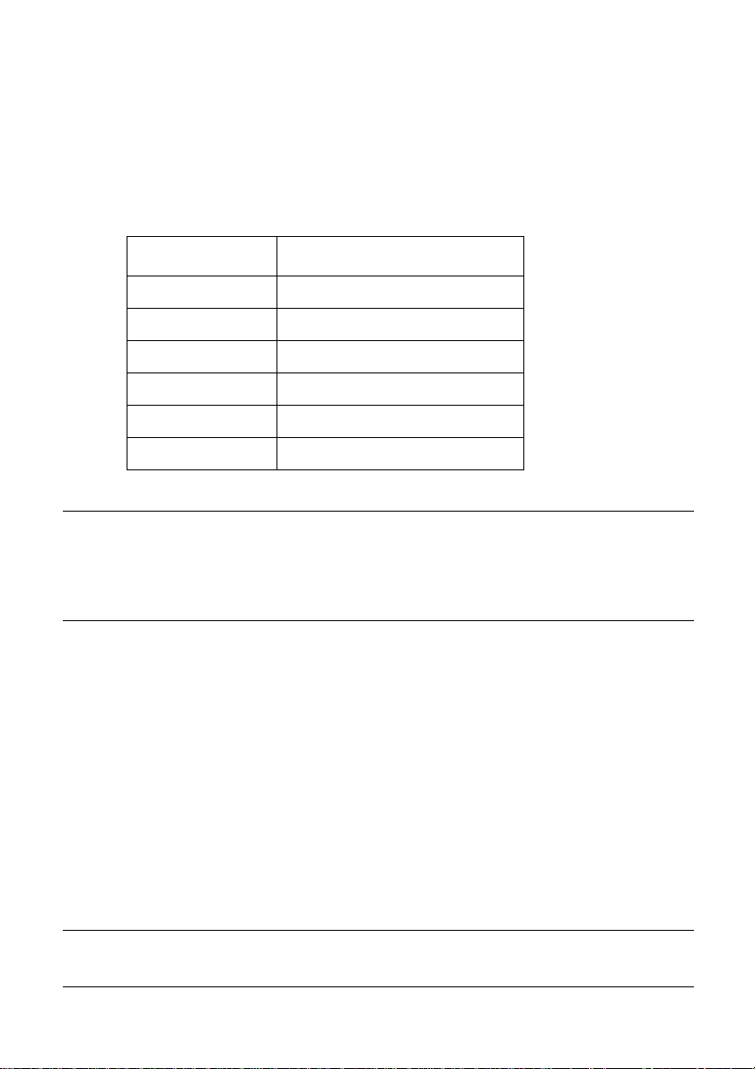
Selecting a bank
While in the EDS Mode, use the control panel’s BANK button to select a
❏
bank. When the BANK indicator flashes it indicates the current bank
selected.
Lit Indicator Selected Bank
A
1
B
2
C
3
D
4
E
5
F
6
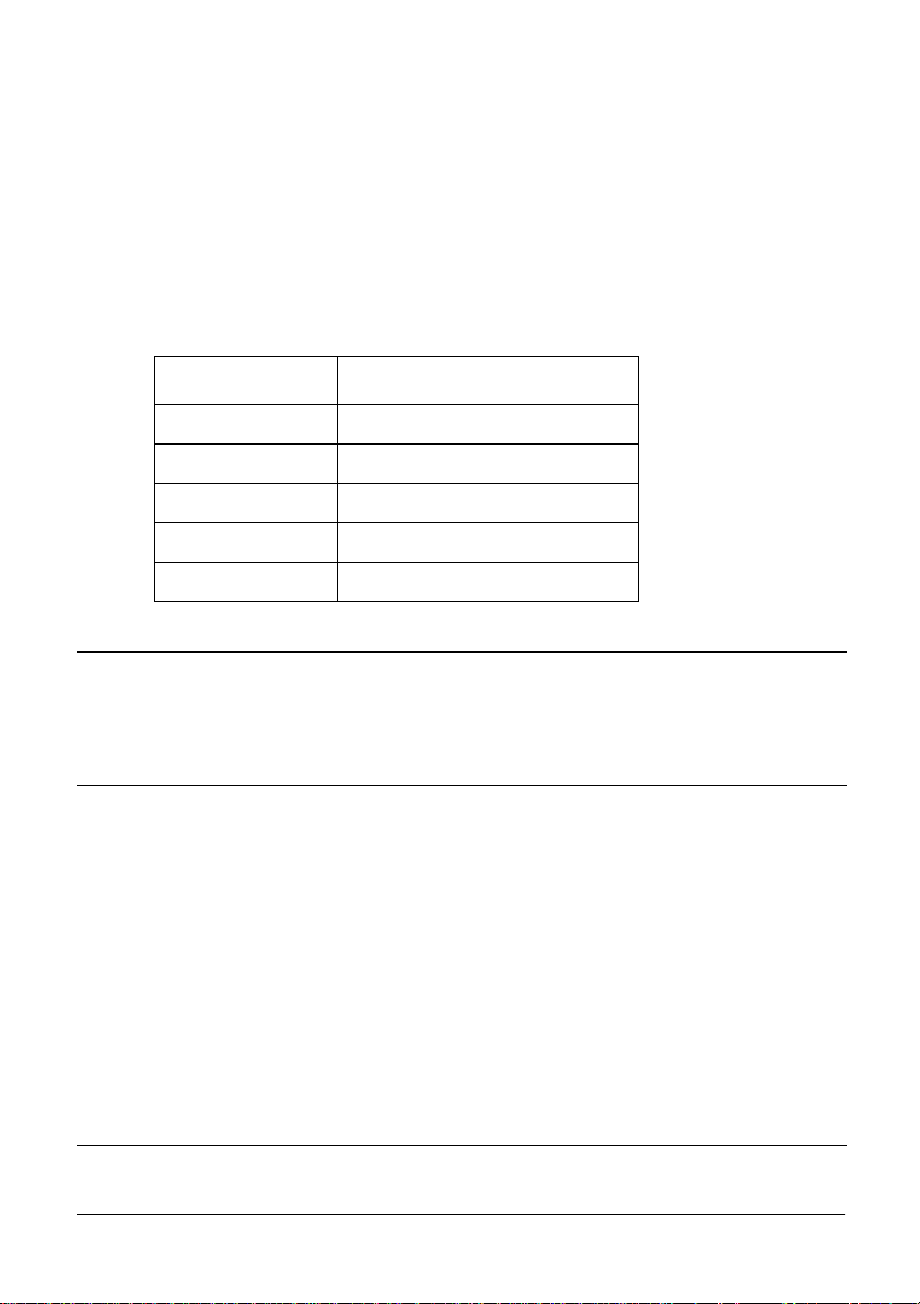
Selecting a switch
While in the EDS Mode, use the control panel’s SWITCH b utton to select a
❏
bank switch. When the SW indicator flashes it indicates the current switch
selected.
Selecting a bank 29
A
B
C
D
E
F
Lit Indicator Selected Switch
A
1
B
2
C
3
D
4
E
5
F
6
Changing a switch setting
After selecting a bank and switch, press the control panel’s ON/OFF
❏
button to turn the switch on and off. The current setting of the switch is
indicated by the ON LINE indicator: the indicator is lit when the switch is
on, and is not lit when the switch is off.
1
2
3
4
5
6
Page 38
30 Using the EDS Mode
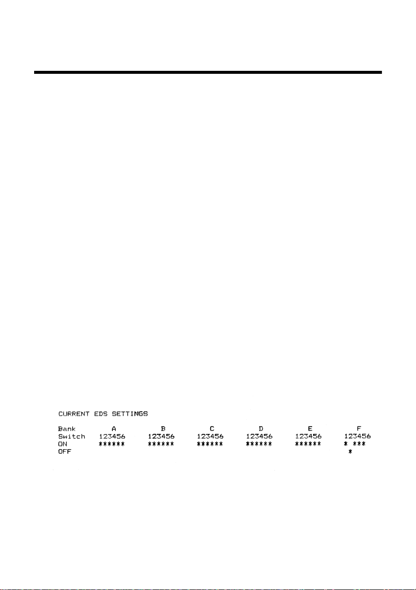
Printing the current switch settings
In the EDS Mode, press the control panel’s PRINT button to print out the
❏
current switch settings. Asterisks on the printout show whether a switch is
turned on or off.
Checking the settings of switches in a bank
After selecting a bank, press the control panel’s STATUS button to view
❏
the status of each switch in that bank. The control panel’s font indicator is
lit when the switch is on, and is not lit when the switch is off.
Lit Indicator Selected Switch
A
1
B
2
C
3
D
4
E
5
F
6
1
2
3
4
5
6
Exiting the EDS Mode
Press the control panels EXIT button to exit the EDS Mode.
❏
Page 39
EDS Mode Settings
The following details all of the settings you can program in the EDS Mode. You
can print out a detailed overview of all the settings by performing a test of the
printer (page 70).
BANK A
Switch 1: Emulation
Selects Standard emulation (ON) or IBM emulation (OFF). Standard emulation
causes the printer to act like the Epson ESC/P (9-pin), while IBM emulation
makes it act like the IBM Proprinter III.
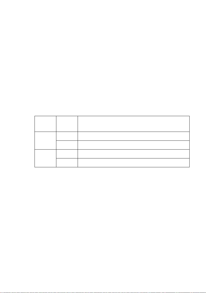
Switch 2: Character Table
The function of this switch depends on whether you are using IBM or Standard
emulation.
EDS Mode Settings 31
Emulation
Standard
IBM
Switch 2
Setting
ON Graphics: IBM Character Set #2
OFF Italics: Italic character table used
ON IBM Character Set #2
OFF IBM Character Set #1
Description
Switch 3: RAM Usage
Specifies whether RAM should be used as an input buffer (ON) or as a
download buffer (OFF). Selecting input buffer (ON) tells the printer to use
available RAM to store data it receives from the computer, which speeds up the
printing. Selecting download buffer (OFF) tells the printer to use available
RAM to store character patterns.
Switch 4: Automatic Sheet Feeder
Specifies whether the optional SF-15HA Automatic Sheet Feeder is installed
(OFF) or not installed (ON).
Switch 5: Paper Out Detector
Specifies whether the printer’s paper out detector is enabled (ON) or disabled
(OFF). When the paper out detector is enabled (ON), the printer automatically
stops printing whenever it senses there is no more paper. When it is disabled
(OFF), the printer continues printing as long as there is data. Selecting disabled
(OFF) makes it possible to print right up to the bottom of a page, but it also
creates the danger of printing when there is no paper loaded in the printer, which
can damage the print head and platen.
Page 40

32 Using the EDS Mode
Switch 6: Multi-Part Mode
Specifies whether the printer’s Multi-Part Mode is enabled (OFF) or disabled
(ON). When the Multi-Part Mode is enabled (OFF), the impact of the print head
is increased, but head life is decreased. Enable the Multi-Part Mode when
printing on four to five-ply paper. Disable the Multi-Part Mode when printing
on 1 to 3-ply paper.
BANK B
Switch 1: Graphics Direction
Selects uni-directional (OFF) or bi-directional (ON) printing for graphics. Bidirectional printing (ON) is faster, while uni-directional (OFF) printing
generally provides better print quality in the graphics mode.
Switch 2: Auto Tear-off (Long)
Specifies whether the printer’s auto tear-off (long) feature (page 24) is enabled
(OFF) or disabled (ON). Note that this setting controls the application
software’s tear-off function only. It does not affect the manual tear-off function
that is performed using the control panel buttons as described on page 18. The
manual tear-off function is always enabled.
Switch 3: Line Spacing
Selects 1/6-inch (ON) or 1/8-inch (OFF) spacing between lines.
Switch 4: Auto LF with CR
Specifies whether auto LF with CR is enabled (OFF) or disabled (ON). When
auto LF with CR is enabled (OFF), the printer automatically performs a line
feed whenever it receives a carriage return from the computer. When it is
disabled (ON), the computer must send both a line feed code and a carriage
return code at the end of each line. Most applications do this automatically. Note
the following check points when trying to figure out which setting to use here:
✓ If you find that your output is double-spaced when it should not be, turn
this switch ON (Disabled).
✓ If you find that lines are printing over each other, turn this switch OFF
(Enabled).
Switch 5: Zero Style
Specifies whether a normal zero (ON) or a slashed zero (OFF) will be used.
Selecting Normal (ON) prints zeros without lines running through them, while
Slashed (OFF) prints zeros with a diagonal slash running through them.
Switch 6: Reserved
Page 41
BANK C
EDS Mode Settings 33
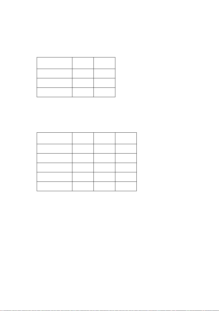
Switches 1, 2: Print Mode
Turn these switches on or off to select the print mode you want to use.
Print Mode SW1 SW2
Draft ON ON
NLQ ON OFF
HS-Draft* OFF ON
* LC-1521 only. Not used with LC-1511.
Switches 3, 4, 5: Print Pitch
Turn these switches on or off to form the pattern that matches the print pitch
setting you want to make.
Print Pitch SW3 SW4 SW5
10cpi ON ON ON
12cpi OFF ON ON
17cpi ON OFF ON
20cpi OFF OFF ON
Proportional ON ON OFF
Switch 6: Quiet
When the Quiet Mode is enabled (OFF), the printer prints with less noise than
normal printing. Though the Quiet Mode prints more quietly, it also takes
considerably longer than normal printing.
Page 42
34 Using the EDS Mode
BANK D
Switches 1, 2, 3, 4: Page Length
Turn these switches on or off to form the pattern that matches the Page Length
setting you want to use.
Page Length SW1 SW2 SW3 SW4
11”/Letter ON ON ON ON
8” OFF ON ON ON
11.7”/A4 ON OFF ON ON
12” OFF OFF ON ON
8.5”/Letter ON ON OFF ON
14”/Legal OFF ON OFF ON
10.5”/Executive ON OFF OFF ON
7.25”/Executive OFF OFF OFF ON
3.5” ON ON ON OFF
5.5” OFF ON ON OFF
BANK E
Switch 5: CR Centering Position
Specifies whether the printer's CR centering is long (ON) or short (OFF). When
the CR centering position is long (ON), the carriage moves to the center of the
platen before the paper is inserted or ejected. When CR centering is short (OFF),
the carriage moves to the left side of the platen.
In order to prevent paper feeding problems, set the CR centering position to
short (OFF) when narrow (less than 5.6″) paper is used and set it to long (ON)
when wider (more than 5.6″) paper is used.
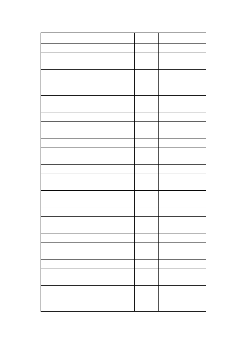
Switches 1, 2, 3, 4, 5: Code Page/International Character Set
If your EDS settings specify IBM emulation (Bank A, Switch 1 OFF) with
either character table (Bank A, Switch 2), or Standard emulation (Bank A,
Switch 1 ON) with the graphics character table (Bank A, Switch 2 ON), use the
Bank E switches to select the default character code page you want to use.
Page 43
EDS Mode Settings 35
Code Page SW1 SW2 SW3 SW4 SW5
#437 IBM-PC ON ON ON ON ON
#850 Multi-lingual OFF ON ON ON ON
#860 Portuguese ON OFF ON ON ON
#861 Icelandic OFF OFF ON ON ON
#863 Canadian French ON ON OFF ON ON
#865 Nordic OFF ON OFF ON ON
#866 Russian ON OFF OFF ON ON
#3840 IBM-Russian OFF OFF OFF ON ON
#3841 Gost-Russian ON ON ON OFF ON
#3843 Polish OFF ON ON OFF ON
#3844 CS2 ON OFF ON OFF ON
#3845 Hungarian OFF OFF ON OFF ON
#3846 Turkish ON ON OFF OFF ON
#3847 Brazil-ABNT OFF ON OFF OFF ON
#3848 Brazil-ABICOMP ON OFF OFF OFF ON
#852 Latin-2 OFF OFF OFF OFF ON
#1001 Arabic ON ON ON ON OFF
#737 Greek OFF ON ON ON OFF
#851 Greek ON OFF ON ON OFF
#869 Greek OFF OFF ON ON OFF
#928 Greek ON ON OFF ON OFF
#2001 Lithuanian-KBL OFF ON OFF ON OFF
#772 Lithuanian ON OFF OFF ON OFF
#774 Lithuanian OFF OFF OFF ON OFF
#3001 Estonian-1 ON ON ON OFF OFF
#3002 Estonian-2 OFF ON ON OFF OFF
#3011 Latvian-1 ON OFF ON OFF OFF
#3012 Latvian-2 OFF OFF ON OFF OFF
#3021 Bulgarian ON ON OFF OFF OFF
#3031 Hebrew OFF ON OFF OFF OFF
#3041 Maltese ON OFF OFF OFF OFF
Page 44
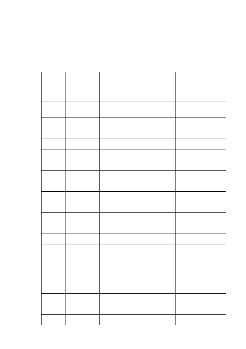
36 Using the EDS Mode
A code page is the set of symbols and characters that your printer can print.
Your printer converts ASCII hexadecimal data according to a code page to print
symbols and characters. By supporting different code pages, the printer can
print in a variety of different languages. The following table shows detailed
information about code pages.
Code Page Name Country Remarks
#437 IBM PC
#850 Multi-Lingual
#860 Portuguese Portugal
#861 Icelandic Iceland
#863 Canadian French Canada
#865 Nordic Denmark, Finland, Norway, Sweden Preferred by Microsoft
#866 Russian Russia Preferred by Microsoft
#3840 IBM-Russian Russia, Bulgaria
#3841 Gost-Russian Russia Gost: government standard
#3843 Polish Poland Also called “Mazowia”
#3844 CS2 Czech Republic Also called “Kamenicky”
#3845 Hungarian Hungary
#3846 Turkish Turkey
#3847 Brazil-ABNT
#3848 Brazil-ABICOMP
#852 Latin-2
United Kingdom, France, Germany, Italy,
Austria, Switzerland, United States, Spain
United Kingdom, France, Germany, Italy,
Austria, Switzerland, United States, Spain
Croatia, Czech Republic, Hungary,
Poland, Romania, Serbia, Slovak
Republic, Slovenia
Preferred by Microsoft
Preferred by Microsoft
#1001 Arabic
#737 Greek Greece Almost 80%
#851 Greek Greece
#869 Greek Greece
Egypt, Saudi Arabia Mainly in Arabic speaking
countries
Page 45
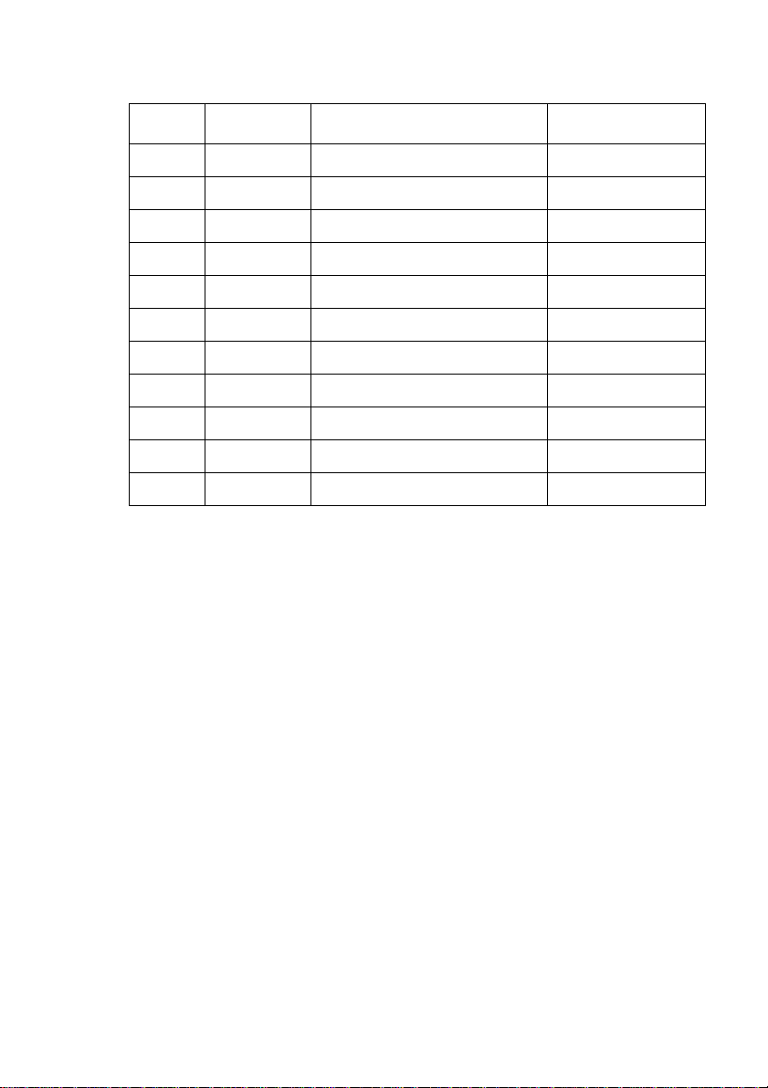
EDS Mode Settings 37
Code Page Name Country Remarks
#928 Greek Greece For UNIX
#2001 Lithuanian-KBL Lithuania Commonly used for DOS
#772 Lithuanian Lithuania New standard
#774 Lithuanian Lithuania
#3001 Estonian-1 Estonia
#3002 Estonian-2 Estonia Most often used
#3011 Latvian-1 Latvia
#3012 Latvian-2 Latvia Government standard
#3021 Bulgarian Bulgaria
#3031 Hebrew Israel
#3041 Maltese Malta
Page 46
38 Using the EDS Mode
If your EDS settings specify Standard emulation (Bank A, Switch 1 ON) with
the italic character table (Bank A, Switch 2 OFF), use the Bank E switches to
select the international character set you want to use. This setting determines the
assignment of 14 character codes in the Standard Italic character set.
International
Character Set
U.S.A. ON ON ON ON ON
France OFF ON ON ON ON
Germany ON OFF ON ON ON
England OFF OFF ON ON ON
Denmark-1 ON ON OFF ON ON
Sweden OFF ON OFF ON ON
Italy ON OFF OFF ON ON
Spain-1 OFF OFF OFF ON ON
Japan ON ON ON OFF ON
Norway OFF ON ON OFF ON
Denmark-2 ON OFF ON OFF ON
Spain-2 OFF OFF ON OFF ON
Latin America ON ON OFF OFF ON
Korea OFF ON OFF OFF ON
Ireland ON OFF OFF OFF ON
SW1 SW2 SW3 SW4 SW5
Legal OFF OFF OFF OFF ON
Page 47
BANK F
Note:
EDS Mode Settings 39
Switches 1, 2, 3, 4, 5: NLQ Font Selection
Turn these switches on or off to form the pattern that identifies the font you want
to use for NLQ printing.
Font SW1 SW2 SW3 SW4 SW5
Roman ON ON ON ON ON
Sanserif OFF ON ON ON ON
Courier ON OFF ON ON ON
Prestige OFF OFF ON ON ON
Orator OFF OFF OFF ON ON
Bank C switches 1 and 2 need to be in the correct positions before the above
setting will have any effect.
Page 48

40
Chapter 4: User Setup Utility
The User Setup Utility is included on the floppy disk that comes with the printer.
It allows you to change the EDS settings of the printer from your computer.
To run the User Setup Utility, you need an IBM-compatible computer running
PC-DOS or MS-DOS. The computer must be equipped with a 3.5″ floppy drive
and a hard disk drive.
In this chapter you will learn about:
❏ Installing the User Setup Utility
❏ Starting the User Setup Utility
❏ Editing setup data
❏ Loading and saving setup data
❏ Exiting the User Setup Utility and sending the settings to the printer
Important!
See the “readme.txt” file for important information that became available after
this documentation was printed.
All the procedures in this chapter assume that you are using a mouse and that
you are familiar with common mouse operations like click and double-click. If
you need information on mouse operations, see your computer manual. If you
want to operate the User Setup Utility using the keyboar d instead of the mouse ,
follow the instructions that appear on your computer’s screen.
Installing the User Setup Utility
Insert the disk that contains the User Setup Utility into one of your
❏
computer’s disk drives. This explanation assumes you are using the A:
drive, but you could use any drive. Just remember to change the “A:” drive
name specifications in the following steps to the name of the drive you are
using.
❏ Execute the following commands to start installation of the User Setup
Utility. The following commands assume you are starting from drive C:,
and the floppy that contains the User Setup Utility is inserted in drive A:.
C:\>A: ↵
A:\>CD UTILITY↵
A:\UTILITY>SETUP↵
Page 49

Starting the User Setup Utility 41
Setting for Install
Language:
English
Printer Type:
LC-1511
Install Directory:
c:\star
F1=Install F2=Cancel
❏ Pull down the list of available languages under Language: and double-
click the one you want to use.
❏ Pull down the list of available printers under Printer Type: and double-
click on the one you want to use. For this printer you should select LC-1511
or LC-1521.
❏ Click the Install Directory: box to change it into an input box.
❏ Input the drive name and directory where you want the User Setup Utility
installed. Make sure to include the full path to the directory.
You can use your computer’s left and right arrow keys, Delete key, and
backspace key to move around the input box and make changes to the text
inside it.
❏ Click Install to install the User Setup Utility and start it up.
Starting the User Setup Utility
After you install the User Setup Utility, you can start it an y time by mo ving
❏
to the directory you specified under “Installing the User Setup Utility” in
the previous section and inputting the following:
STARSET ↵
Page 50

42 User Setup Utility
Note:
Help
F1
Exit
F2
Emulation
Standard
RAM usage
Input Buffer
Quiet mode
Disabled
File
General
F3
*
*
*
F4
Font
F5
General
Graphic Direction
Bi-direction
CR Centering Position
Long
PaperF6Adjust
*
*
F7
Port
F8
When you start the User Setup Utility, it reads and displays the last settings
that were sent to the printer by the utility.
The utility does not read the settings from the printer. It reads the settings from
a file that was created the last time the utility was run, which ar e stor ed on your
computer’s hard disk. If the EDS settings have been changed using the
printer’s control panel, those control panel settings will not be shown by the
utility, and they will be replaced by the current User Setup Utility settings if
you specify that current settings should be sent to the printer (page 45) when
you exit the utility.
❏ Now you can use the User Setup Utility to make the setup changes you
want.
You can press the F1 function key at any time to access on-screen help for
the setup utility.
Changing the General, Font, Paper and Adjust Settings
The following are basic operations to change settings in the General, Font,
Paper and Adjust windows.
To select a window
❏ Click on the name of the window you want to select (General, Font,
Paper, Adjust, Port) by clicking on its name at the top of your computer’s
screen. When you do, the corresponding window appears on the screen.
You can also select a window by pressing a function key from F4 to F8.
Page 51
To select a setting box
❏ Click on the box you want to select or move to by using your keyboard’s
Tab or arrow keys. The currently selected setting box is highlighted on
the screen.
To change a setting
❏ After you select a setting box, click on the box or press Enter to pull down
a list of available settings.
❏ Select the setting you want to use in the list by double-clicking on it, or by
moving to it with the arrow keys and pressing Enter.
Note:
An asterisk to the right of a setting indicates that it is the default.
The settings in the General, Font, and Paper windows are identical to those in
the EDS Mode. See “EDS Mode Settings” on page 31 for details.
Adjusting the dot alignment
Click on Adjust or press the F7 function key.
❏
Adjusting the dot alignment 43
Multi-Part Mode
Normal Mode
DRAFT
0
D-Density/Speed
0
D-Density P-Graphics
0
NLQ
0
Quadruple-Density
0
F9:Test F10:Test All
*
*
*
*
*
*
Adjust
Normal-Density
0
Plotter-Graphics
0
CRT Graphics I
0
CRT Graphics II
0
Double-Density
0
*
*
*
*
*
❏ Use the above window to test and adjust the vertical alignment of the
printer in each printing mode. See “Adjusting the dot alignment” on
page 72 for full details on dot alignment.
Page 52
44 User Setup Utility
Changing the printer port
Click on Port or press the F8 function key.
❏
Port
Lpt1:
Com1:
Com2:
❏ Select the port you want to use by double-clicking on it, or by moving to it
with the arrow keys and pressing Enter.
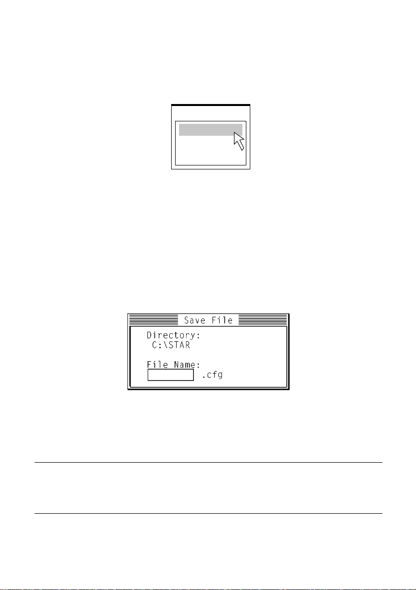
Saving setup data in a configuration file
To save setup data in a configuration file so you can recall it later, click on
❏
File or press the F3 function key.
❏ Select Save from the menu that drops down by double-clicking on it, or by
moving the highlighting to it with the arrow keys and pressing Enter.
❏ Input the name that you want to assign to the configuration file and press
Important!
Remember that changing User Setup Utility settings on the computer screen
does not directly change them in the printer. To change the printer settings to
those shown on the screen, use the Exit command (page 45).
Enter. The configuration is automatically stored in the directory you
specified under “Installing the User Setup Utility” on page 40, and assigned
the extension “.cfg”.
Page 53
Importing setup data from a configuration file 45
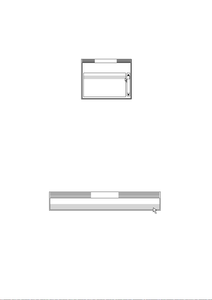
Importing setup data from a configuration file
Click on File or press the F3 function key.
❏
❏ Select Load from the menu that drops down by double-clicking on it, or by
moving the highlighting to it with the arrow keys and pressing Enter.
File
C:\STAR\*.cfg
.. <DIR> 1995-06-15
DEFAULT .CFG 1995-06-15
PREVIOUS.CFG 1995-06-22
Load file
❏ Select the file that contains the configuration you want to use by double-
clicking on its name, or by moving the highlighting to its name with the
arrow keys and pressing Enter.
Returning to default settings
To make all settings revert to their defaults, perform the procedure under
❏
“Importing setup data from a configuration file” in the previous section and
select the file named “DEFAULT.CFG”.
Exiting the User Setup Utility
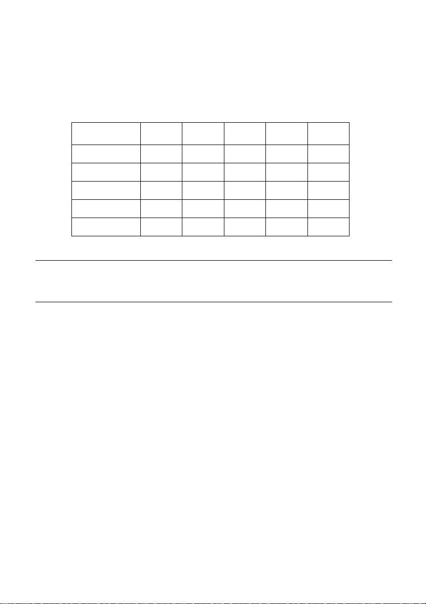
To exit the User Setup Utility, pull down the File menu and select Exit.
Exit without sending current settings.
Exit after sending current settings.
❏ Select the option you want by double-clicking on it, or by moving the
highlighting to it with the arrow keys and pressing Enter.
“Exit after sending current settings” sends all User Setup Utility settings to
the printer, which replaces any settings that may have been made using the
printer’s control panel. “Exit without sending current settings” exits the
User Setup Utility without sending anything to the printer.
Using the Help menu
T o get information on ho w to use the User Setup Utility, click Help or press
❏
function key F1.
Exit
Page 54

46
Chapter 5: Using the Printer with Windows 3.1
This chapter contains specific information you need to know when using the
printer with Microsoft Windows 3.1 or later. It also tells you how to install the
printer driver on your computer so that it can control the printer correctly. In this
chapter, you will learn about:
❏ How to set up for printing with Microsoft Windows 3.1
❏ How to prepare for printing
❏ How to print a document
❏ How to install TrueType fonts
❏ How to select fonts from within an application
Important!
See the “readme.txt” file for important information that became available after
this documentation was printed.
Setting up for printing with Microsoft Windows 3.1
This printer is designed to work best with computers running Microsoft
Windows 3.1. If you are running an earlier version of Windows, we recommend
that you upgrade to 3.1.
Before you can use the printer with Windows, you must first use the procedure
outlined below to install the printer driver that is supplied on the 3.5” floppy
disk that comes with the printer. This procedure assumes that you are using a
mouse and that you are familiar with common mouse operations like click and
double-click. If you need information on mouse operations or if you want to
install the printer driver without using a mouse, refer to your Microsoft
Windows User’s Guide.
❏ Insert the disk that contains the printer driver into one of your computer’s
disk drives. This explanation assumes you are using a drive named “A:”,
but you could use any drive. Just remember to change the “A:” in the
following steps to the name of the drive you are using.
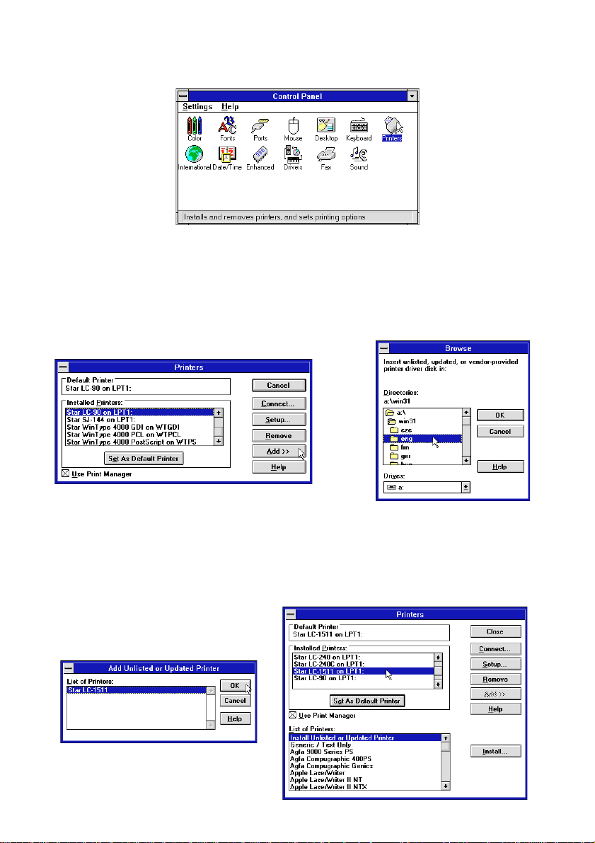
❏ In the Main group, double-click on the Control Panel icon.
❏ Double-click on the Printers icon in the Control Panel window.
Page 55
Setting up for printing with Microsoft Windows 3.1 47
❏ Click Add and the dialog box will expand to show a List of Printers.
❏ In the List of Printers: box, select Install Unlisted or Updated Printer.
❏ Click Install.
❏ This causes the Install Driver dialog box to appear, which instructs you to
insert the disk that contains the printer driver file.
❏ Click Browse.
❏ In the Directories: list, select WIN 31.
❏ Click on the language you want to use and then click OK.
We will use English in all of our examples here.
Page 56

48 Using the Printer with Windows 3.1
❏ In the List of Printers: box of the Add Unlisted or Updated Printer
dialog box, select the Star printer driver and then click OK.
This causes the Printers dialog box to appear. The STAR printer is now
listed in the Installed Printers: list.
❏ Double-click on the name of the printer model you just installed to select it
as the default printer.
❏ Click Close to close the Printers dialog box.
Note:
Windows applications automatically print on the currently selected default
printer. If you want to print on a different printer, you must first select it.
Getting ready to print
Before printing, there are a number of things you must first do to set up the
printer. You must select the printer driver, and the paper source, size, and
orientation. Use the following procedure to make these selections.
Note:
You do not need to perform printer driver and paper selections mentioned
above each time you print, but only if there are any changes to the last
selections you made.
❏ In the Windows Program Manager, open the Main group by clicking on its
icon.
❏ Double-click on the Control Panel icon.
❏ Double-click on the Printers icon in the Control Panel window.
❏ Double-click on the name of the printer model you selected above to
choose it as the default printer.
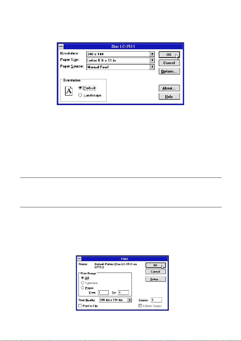
❏ Click on Setup to display the window for setting up your printer.
Page 57
Note:
Printing a document 49
❏ From this window you select buttons that let you control a wide variety of
printer setup parameters. This manual does not include any information
about how to do this because everything you need to kno w is included in an
on-line manual that tells you how to use all the buttons and menus that
appear. To view the on-line manual, click on the Help button.
❏ After the printer is set up the way you want it, click on OK.
❏ Click on the Close button in the Printers window to save your setup and
return to the Program Manager.
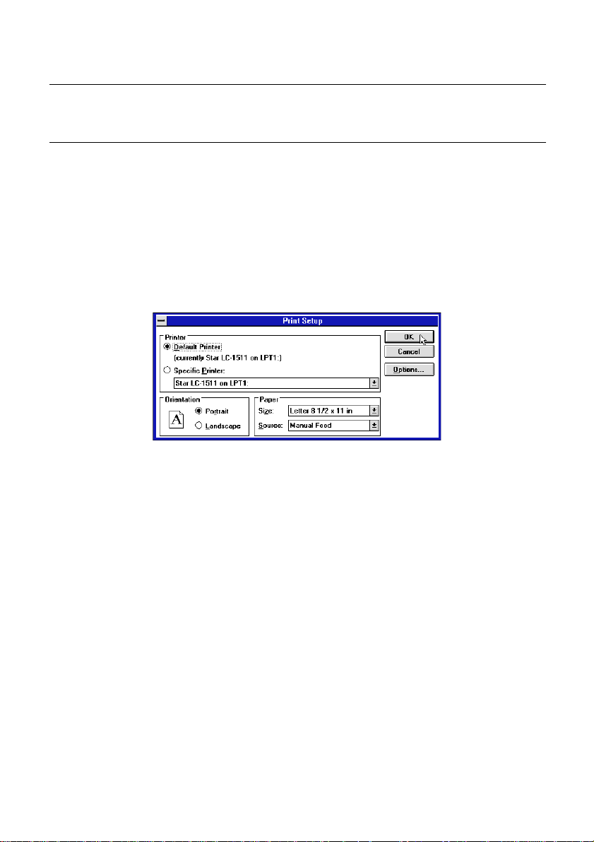
Depending on the application software you are using, settings similar to those
in the above procedure can be made using the Print Setup command of the
File menu instead of the Control Panel.
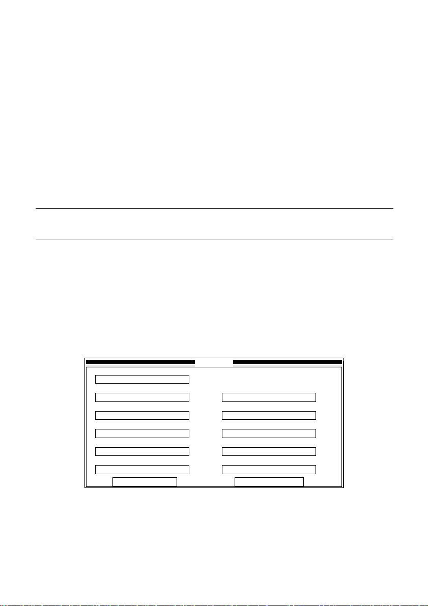
Printing a document
The following Print window appears when you select the Print command
of the File menu of your Windows application.
Page 58
50 Using the Printer with Windows 3.1
Note:
The actual appearance of the Print window may differ somewhat depending on
the application you are using.
Use this window to specify the range of the pages to be printed, the quality of
the printing (in dots per inch), and the number of copies you want to print. Note
also that there are boxes that you can select to specify printing to a file or
collating (printing from back to front).
You can change the printer setup by clicking on the Setup button. When you
do, the following window for setting up your printer appears on the display.
Make changes by clicking on the appropriate radio button or highlighting your
selection on the appropriate pull-down menu.
Installing TrueType fonts
The TrueType fonts that are supplied on one of the 3.5” floppy disks that come
with the printer can be used only when you are running Windows 3.1 or later.
Use the following procedure to install the fonts.
❏ Launch Windows.
❏ Close any applications that may be open.
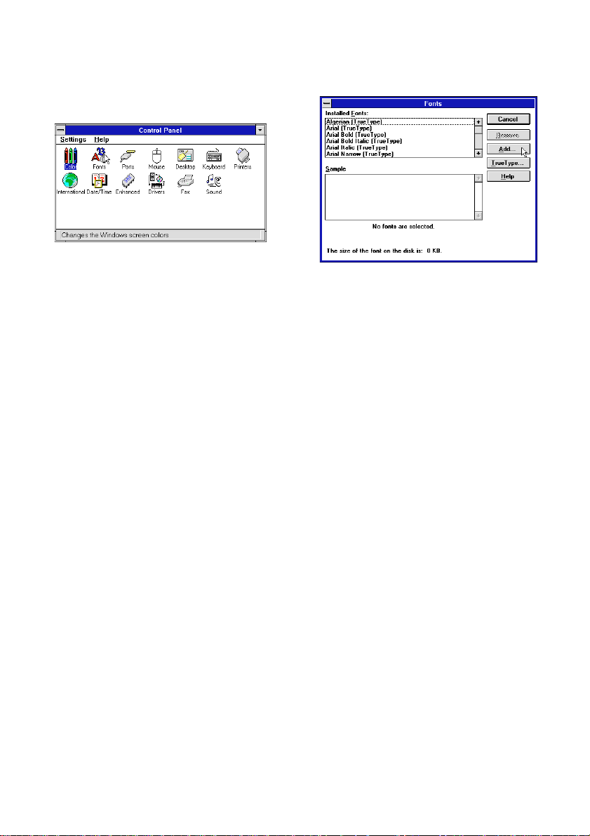
❏ Open the Windows Control Panel.
❏ Double-click the Fonts icon and the Fonts dialog box appears.
❏ Click Add and the Add Fonts dialog box appears.
Page 59
Selecting fonts in Windows applications 51
❏ Insert the disk that contains the fonts into one of your computer’s disk
drives. This explanation assumes you are using a dri ve named “A:”, but you
could use any drive. Just remember to change the “A:” in the following
steps to the name of the drive you are using.
❏ Select the letter that represents the drive where the floppy disk is installed.
When you do, the names of all the fonts on the disk appear in the List of
Fonts window. Select the fonts you want to install by clicking on their
names. If you want to install all of the fonts, click Select All.
❏ Click OK. The Fonts dialog box appears and installation is performed. The
names of the newly installed fonts are automatically added to the Installed
Fonts list.
❏ If you were in an application program when you installed the new fonts,
you will need to select Printer Setup from the application’s FILE menu,
and reselect the printer. After that, the application can display on-screen
text and print text on the printer using the newly install fonts.
Selecting fonts in Windows applications
Refer to the manual of the application you are using for details on how to select
fonts within that application.
In addition to the Windows fonts, you can also use the TrueType fonts that come
with this printer.
Page 60
52
Chapter 6: Using the printer with Windows 95
This chapter describes how to use the printer with Microsoft Windows 95. The
following topics are covered:
❏ Setting up the printer in Windows 95
❏ Preparing for printing
❏ Printing a document
❏ Installing the TrueType fonts
Note:
The file “readme.txt” on the floppy disk contains any late-br eaking information
that has been made available since this manual was printed.
Setting up the printer in Windows 95
To use the printer with Windows 95, you need to install a file known as the
printer driver onto your computer. This file is supplied on the floppy disk that
comes with the printer.
The following description assumes that you are using a mouse (“click” and
“double-click” refer to the action of using the mouse to point at an item with the
on-screen pointer, and then clicking either once, or twice in quick succession).
To install the printer driver under Windows 95, use the following steps:
❏ Turn on the printer and start up your computer.
❏ Click on the Start button in the bottom lefthand corner of the screen.
❏ Select Settings.
❏ Release the mouse button on Printers.
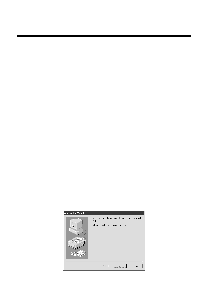
❏ Double-click on the Add Printer icon in the Printers window.
❏ Click on the Next button.
Page 61
Setting up the printer in Windows 95 53
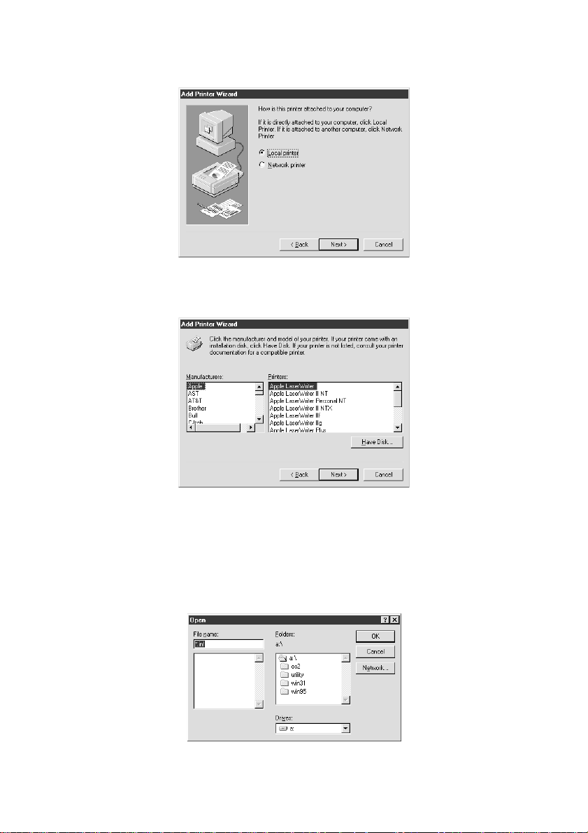
❏ When the above window is displayed, make sure the Local printer radio
button is checked. Then click on the Next button twice, and click on the
Back button.
❏ Click on the Have Disk button.
❏ Insert the disk with the printer driver file on it into the floppy disk drive.
Make sure that the drive’s name (“A:” or “B:”) is displayed in the field
named Copy manufactur er’ s files fr om:. To select a drive name, click on the
arrow by the side of the field and select the drive from the list that appears.
❏ Click on the Browse button. A list of folders on the floppy disk is
displayed.
❏ Select “WIN95” (either by double-clicking on it or by clicking on it and
clicking on the OK button).
❏ Click on the OK button twice.
Page 62
54 Using the printer with Windows 95
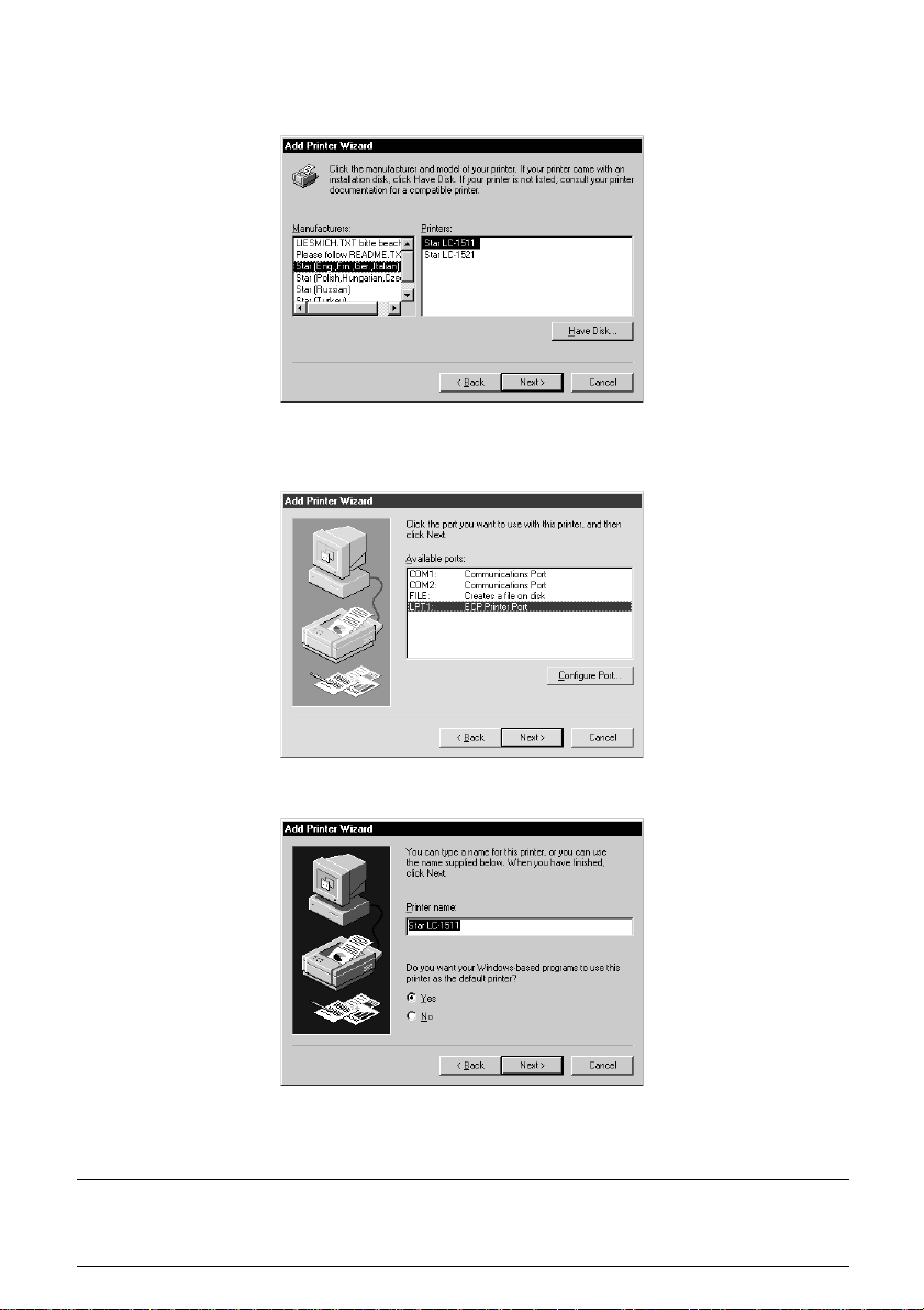
❏ Select the language or language group you want to use by clicking on it.
❏ Select the printer model name (“Star LC-1511” or “Star LC-1521”) by
clicking on it and then click on the Next button.
Note:
❏ Select the printer port to which the printer is connected by clicking on it
(usually “LPT1”). Click on the Next button.
❏ Change the printer name if you want. If you have previously installed
another printer, you must select whether you want the new printer to be the
default printer. Click on the appropriate radio button.
Windows applications always print to the currently selected default printer,
unless the user chooses a different printer from within the application.
Page 63

❏ Click on the Next button.
❏ Select whether to print out a test page by clicking on the appropriate radio
button.
❏ Click on the Finish button.
❏ If a message appears requesting you to insert the Windows 95 CD-ROM,
insert it into the CD-ROM drive and click on the OK button.
❏ If a message appears saying that the printer driver file LC15X1.DRV cannot
be found on the Windows 95 CD-ROM, click on the Bro wse button, select
the floppy disk drive’s name (“A:” or “B:”), click on “WIN95” in the list of
directories and click on the OK button (or double-click on “WIN95”).
❏ Click on the OK button.
This concludes the printer set-up.
Preparing to print
Often you can simply select the Print command in the application you are
using, click the OK button, and your document will be printed out. However,
sometimes you may need to change certain settings beforehand, such as the
default printer, which port a printer uses, which printer driver it uses, the paper
size, the paper source etc.
Settings are made by checking radio buttons, entering numbers into fields or by
clicking on the arrow by the side of a field and selecting an option from the list
that appears. All these settings, and how to make them, are fully explained in
the Microsoft Windows 95 User’s Guide.
Some settings, e.g. paper size and paper source, can be made within an
application when you select the Print command (see the next section:
Printing a document). However, settings made within an application only affect
printing from that application.
To change the default printer and to make general settings that will apply to any
application, proceed as follows:
❏ Click on the Start button in the bottom lefthand corner of the screen.
❏ Select Settings.
❏ Release the mouse button on Printers.
Preparing to print 55
Page 64
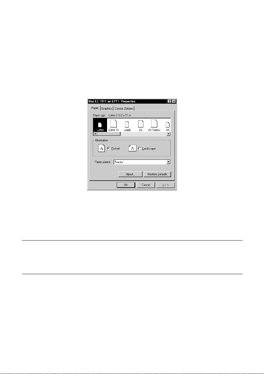
56 Using the printer with Windows 95
❏ Double-click on the icon bearing the name of the printer (Star LC-1511 or
Star LC-1521) in the Printers window. A window appears listing any
documents that are currently being printed on the printer.
❏ Click on the Printer menu.
❏ To set the printer as the default printer, click on the Set As Default
command so that a tick mark appears in the check box. This denotes that
the selected printer is the default printer.
❏ Click on the Printer menu and click on the Properties command.
❏ Click on any of the five index-card type buttons and change the parameter
settings as you require. For a detailed explanation of any of the settings,
click on the “?” button on the top right of the window and then click on the
relevant parameter field. Click once more to clear the help message from
the screen.
Note:
Paper, Graphics
select the
application only apply to printing from that application.
Print
and
Device option
command in an application. However, settings made within an
settings can also be made when you
❏ Click on the Close (X) button on the top right of the Properties window.
❏ Click on the Close (X) button on the top right of the printer’s window
This concludes the printing preparation. The printer which you selected is now
the default printer, and the page size, paper source setting and any other settings
which you made for the printer, apply to printing from all applications. To
override these settings for a specific application, refer to the next section,
Printing a document.
Page 65
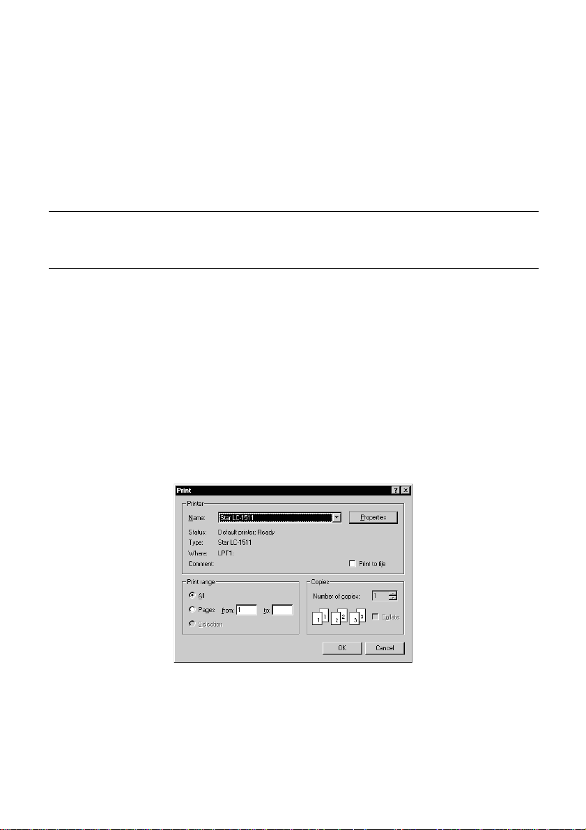
Printing a document
Windows 95 applications always print to the currently selected default printer.
If you want to change the default printer, refer to the previous section,
Preparing to print.
To print from any Windows 95 application, proceed as follows:.
❏ Click on the application’s File menu.
❏ Click on the Print command.
Note:
The actual appearance of the Print window may differ somewhat depending on
the application you are using.
❏ If you do not want to use the default printer, select a different printer by
clicking on the arrow by the side of the Name field and selecting one from
the list that appears.
❏ Click on the Properties button.
❏ If you want to change any of the printing settings, for example paper size,
orientation or paper source, click on the appropriate index card-type button
(Paper , Graphics or Device options) and change the parameter
settings as you require.
For a detailed explanation of any of the settings, click on the ? button on
the top right of the window and then click on the relevant parameter field.
Click once more to clear the help message from the screen.
Changes you make here apply only to printing from the current application
❏ Click on the Close (X) button on the top right of the window.
Printing a document 57
❏ Select how many copies of the document will be printed by entering the
appropriate number into the Number of copies field. If you want to print all
the pages in your document, make sure that the All radio button is checked.
If you do not want to print all the pages in your document, enter the first
and last pages to print into the from and to fields.
❏ If you want the output to be collated (each copy automatically sorted into
page order) or if you want to print to file (instead of a print-out, a graphic
file of the print-out is saved on disk), check the appropriate radio button.
❏ Click on the OK button.
Your document will now be printed out.
Page 66
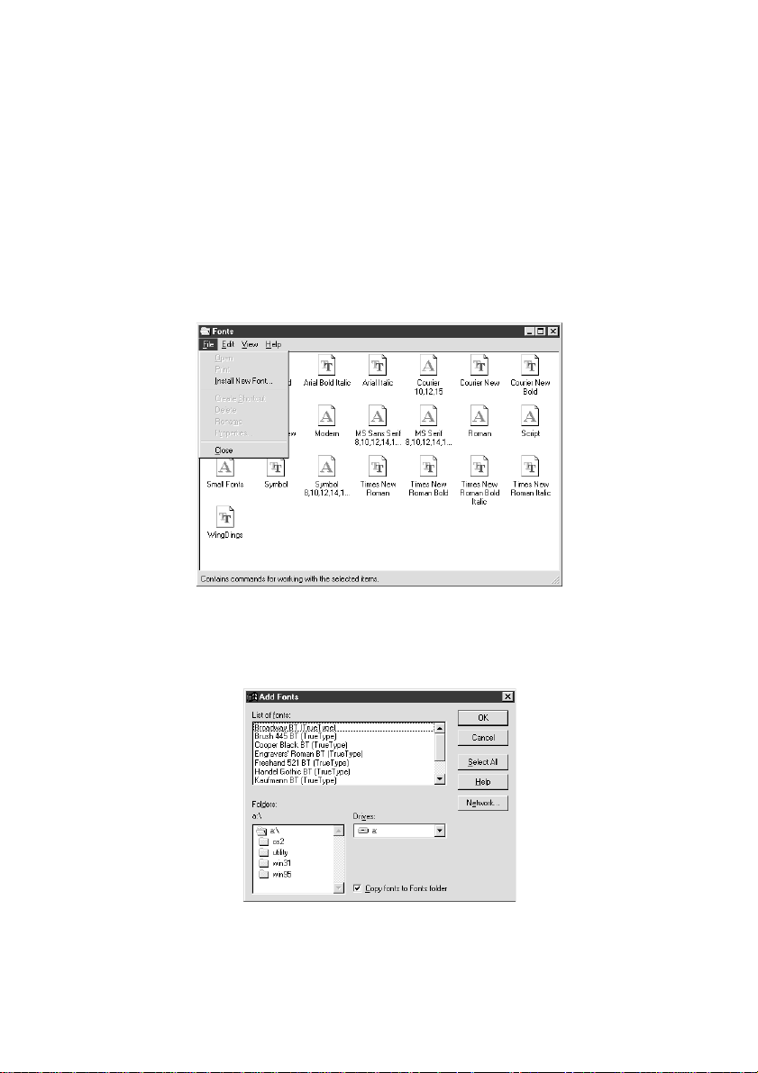
58 Using the printer with Windows 95
Installing TrueType fonts
To install the TrueType fonts that are on the floppy disk accompanying this
printer, follow the procedure below.
❏ Insert the disk in your computer’s floppy disk drive.
❏ Click on the Start button in the bottom lefthand corner of the screen.
❏ Select Settings.
❏ Release the mouse button on Control Panel.
❏ Double-click on the Fonts folder. The currently-installed font files are
displayed.
❏ Click on the Files menu.
❏ Click on the Install New Font... command.
❏ Display the drive’s name (“A:” or “B:”) in the Drives field. To select a driv e
name, click on the arrow by the side of the field and select the drive from
the list that appears. The names of the fonts stored on the disk are displayed
in the List of fonts window.
❏ Select the fonts you wish to install by clicking on them. If you want to
install all of them, click on the Select All button.
❏ Click on the OK button.
The new fonts can now be seen in the Fonts folder window. This concludes the
font installation.
Page 67

Chapter 7: Using the Printer with OS/2 Warp
This chapter contains specific information about using the printer with IBM
OS/2 Warp. It also shows you how to install the printer driver on your computer
so you can control the printer. By reading this chapter, you will learn:
❏ How to set up for printing with IBM OS/2 Warp
❏ How to prepare for printing
❏ How to print a document
Important!
See the “readme. txt” file for important information that became available
after this documentation was printed.
Setting up for printing with OS/2 Warp
Before you can use the printer with OS/2 Warp, you must first perform the
following procedure to install the printer driver supplied on the 3.5” floppy disk
that comes with the printer.
❏ Start up the OS/2 system.
❏ Insert the floppy disk that comes with the printer into one of your
computer’s disk drives.
❏ Open the floppy in icon view.
❏ Double click on the OS2\ENG folder.
❏ Double click on the STARDM.DR_ file.
❏ Drag the printer driver whose name matches the name of your printer to the
desktop.
59
Page 68

60 Using the Printer with OS/2 Warp
Getting ready to print
There are several steps to set up the printer before using it. You must select the
printer driver, and specify the source, size, and orientation of the paper. Use the
following procedure to make these selections.
Note:
You do not need to select the printer driver and paper specifications each time
you print, but only if you want to change any of your previous settings.
❏ Point to the printer object.
❏ Click mouse button 2.
❏ Select Settings.
❏ Select the Printer driver tab.
❏ Point to the printer driver you want to use.
Click mouse button 2.
❏ Select Settings to display the Properties window for setting up your
printer.
With the Properties window, you can click on various buttons to control a
wide variety of printer setup parameters. Everything you need to know about
these settings is included in an on-line manual that tells you how to use all
the buttons and menus that appear on your computer’s screen. To view the
on-line manual, select Help.
❏ After you get the printer set up the way you want it, select Save.
Printing a document
Select the Print command in the File menu of the application you are using.
Page 69

Chapter 8: Using the Printer with MS-DOS
This chapter contains information about how to use the printer with applications
software running under MS-DOS. In this chapter, you will learn about:
❏ How to set up for printing with MS-DOS
Setting up for printing with MS-DOS
To print from an application running under MS-DOS, you must first select the
printer from within the application. Typically, the program will feature an
INSTALL or SETUP command for selection of printers. Refer to the manual
for the application you are using for details on how to select a printer for it.
❏ Start up the application and use the correct procedure for that application to
select a printer. The following is a list of printers that can be used. If your
application lists more than one of these, select the printer that is nearest to
the top of this list. You should also use the EDS mode or User Setup Utility
to select Standard emulation (page 31).
Star LC-1511/1521
Star XR-1520/ZA-250
Star XR-1500/FR-15
61
Epson FX-1170
Epson EX-800
If none of the printers listed above are available in the application, choose
one of the printers listed below. Once again, you should choose the printer
that is nearest to the top in the following list. For these printers, you should
use the EDS Mode or User Setup Utility to select IBM emulation (page 31).
IBM Proprinter III
IBM Proprinter II
IBM Proprinter
❏ To print, follow the instructions given in the manual of the application you
are using. Typically, you would select the application’s PRINT command,
make any necessary changes in the window that appears (such as the
number of copies to be printed), and then press the Enter key to start
printing.
Page 70

62
Chapter 9: Paper Handling
Your printer is designed to print on a variety of paper types. This chapter tells
you everything you need to know about paper, and how to set the printer up for
manual paper feed. In this chapter, you will learn about:
❏ Selecting the best type of paper
❏ Adjusting for paper thickness
❏ Manual sheet feeding
❏ Clearing paper jams
Selecting paper types
Use the following information when selecting paper.
Cut-Sheet Paper (Manual Feed)
Width: 7.0″ to 16.54″ / 178 to 420mm
Length: 5.5″ to 14″ / 140 to 356mm
Thickness: 0.00276″ to 0.00472″ / 0.07 to 0.12mm
Weight: 14 to 24 lbs / 52 to 90g/m2 / 45 to 77 kg
Cut-Sheet Paper (with Optional Automatic Sheet Feeder)
Paper size: B5, A4, LT, B4, A3, Legal
Thickness: 0.00315″ to 0.00472″ / 0.08 to 0.12mm
Weight: 16 to 24 lbs / 60 to 90g/m2 / 52 to 77 kg
Hopper: 50 sheets of 64g/m
30 sheets of 80g/m
Stacker: 10 sheets
Fanfold Paper
Width (push feed): 4″ to 16.5″ / 101.6 to 419mm
Width (pull feed): 4″ to 16.0″ / 101.6 to 406mm
Thickness: 0.00276″ to 0.00433″ / 0.07 to 0.11mm (1-ply)
0.01378″ / 0.35mm max. (total thickness of multi-ply, noncarbon)
Weight: 14 to 22 lbs / 52 to 82g/m2 / 45 to 70 kg (one-ply)
11 to 14 lbs / 40 to 52g/m2 / 34 to 45 kg (multi-ply)
Copies: Original + 1 or 2 (Normal Mode)
Original + 3 or 4 (Multi-Part Mode)
Multi-part Mode and an optional pull tractor are
recommended when printing on 4 or 5-ply paper.
2
2
Page 71
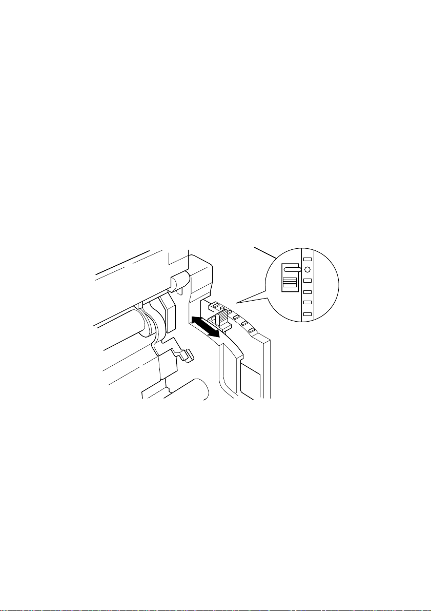
Labels
Backing sheet: 4.5″ to 16.5″ / 114 to 419mm
Thickness
Backing sheet: 0.00276″ to 0.0035″ / 0.07 to 0.09mm
Total: 0.0075″ / 0.19mm
• Use labels under normal temperature and humidity conditions only.
Adjusting for paper thickness
Paper comes in different weights, normally expressed as gsm (grams per square
meter) or lbs (pounds). Some forms paper also have multiple pages that make
them quite thick. Use the following procedure to change the gap between the
print head and the platen and adjust for paper thickness.
Adjusting for paper thickness 63
1
2
3
4
5
6
❏ Move the adjustment lever to one of its four settings. Position 2 is most
suitable for single-sheet paper.
Page 72
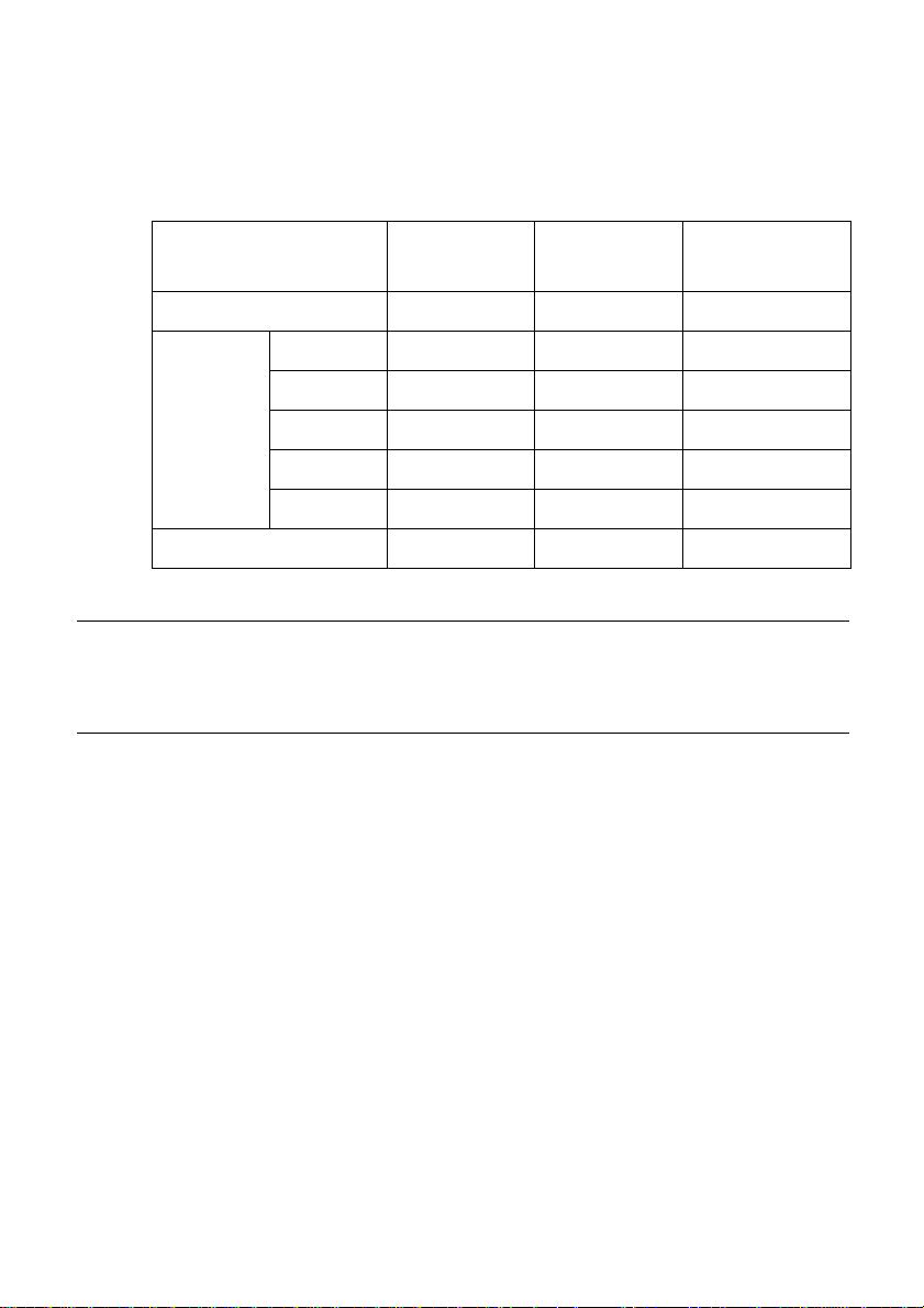
64 Paper Handling
The following table provides a general guide for setting the adjustment lever.
Experiment with different settings until you find the one that gives you the print
quality you want.
Paper Type Weight Per Sheet Thickness
Cut-sheet 52 to 90 g/m
1-ply 52 to 90 g/m
2-ply 40 to 52 g/m
Fanfold
Labels (with backing sheet) — — 3 or 4
3-ply 40 to 52 g/m
4-ply 40 to 52 g/m
5-ply 40 to 52 g/m
Important!
Continuous use of the wrong adjustment lever setting can drastically reduce
print head life! The Multi-part Mode is only recommended when printing on 4
or 5-ply paper.
Automatic fanfold feeding
See “Loading fanfold paper” on page 12 for details on using fanfold paper.
❏
2
0.07 to 0.12mm 1 or 2
2
0.07 to 0.12mm 2 or 3
2
0.12 to 0.16mm 2 or 3
2
0.18 to 0.25mm 3 or 4
2
0.24 to 0.30mm 4 or 5
2
0.30 to 0.35mm 5 or 6
Recommended
Position
Manual sheet feeding
You can use the following procedure to manually feed single sheets of paper
into the printer.
❏ Make sure that there is no fanfold paper in the printer. If there is, use the
procedure under “Parking fanfold paper” on page 17 to park the fanfold
paper and prepare for manual sheet feeding.
❏ Move the paper guide so that it is at a 70-degree angle. (Refer to page 10.)
❏ Set the release lever to the cut-sheet position.
❏ Align the left paper guide with the scale mark that matches the size of the
paper you are using.
Page 73
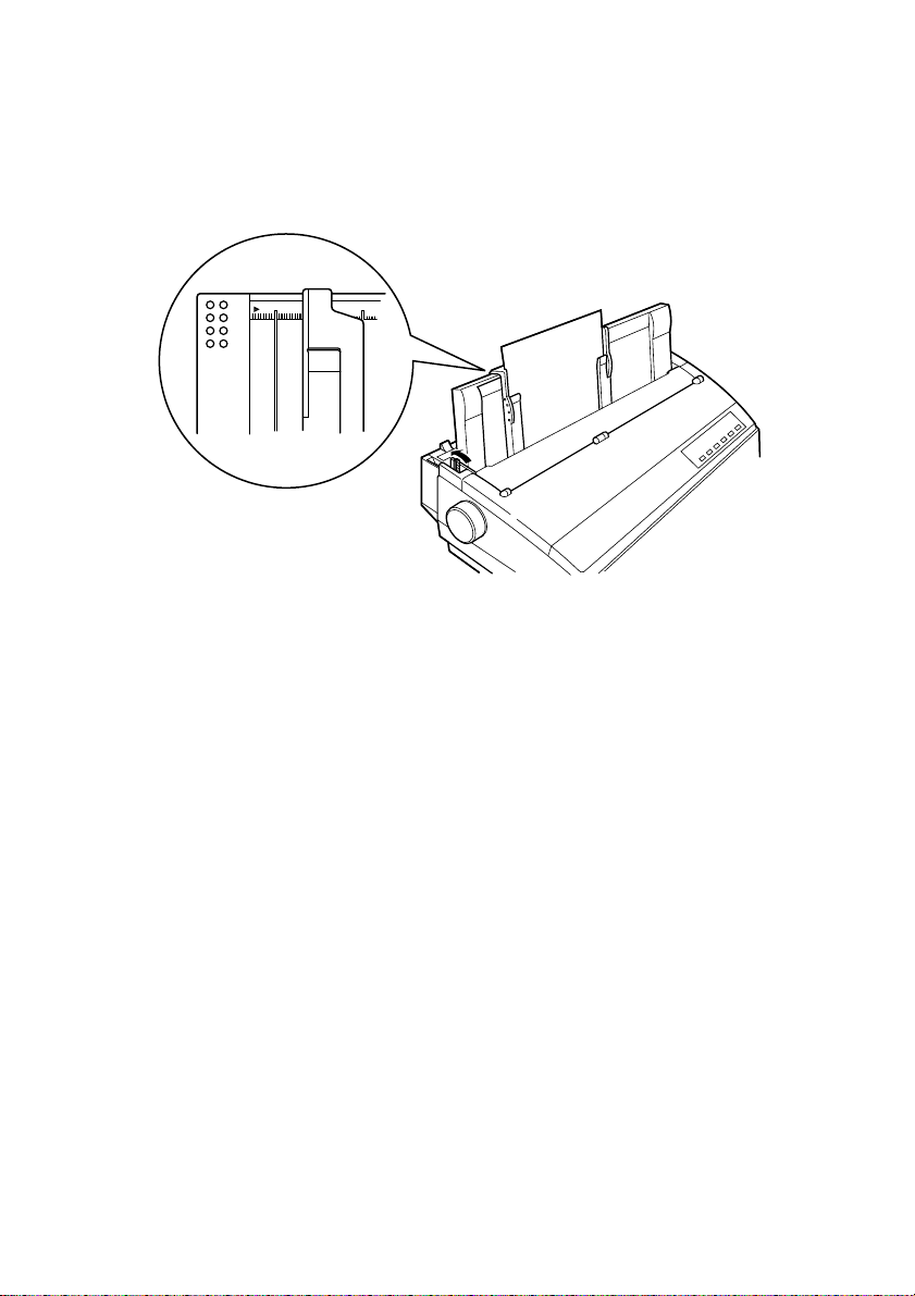
❏ Adjust the right paper guide so there is enough space to insert the paper.
Paper guide
Release lever
❏ Insert a sheet of paper into the paper guide, with the side you want to print
❏ Press the SET/EJECT/PARK button to feed the paper to the starting
❏ If you want to move the paper to another position, use the micro feed
❏ Start the printing operation from your software application.
Clearing paper jams 65
For any paper size other than A3 landscape (horizontal), align the paper
guide with scale 0 (zero). For A3 landscape paper, align the paper guide with
▲
the mark.
020
on facing the back of the printer. Gently push the paper down into the
printer until you feel it stop.
position.
function described under “Micro feed” on page 23.
Clearing paper jams
Use the following procedure to clear paper jams from the printer.
❏ Unplug the printer from its AC power outlet.
❏ Open the front cover of the printer.
❏ Carefully try to pull the jammed paper from the printer.
If necessary, change the release lever position or rotate the platen knob to
remove the paper.
Page 74
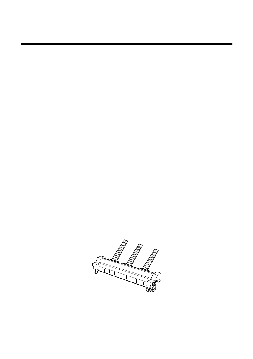
66
Chapter 10: Optional Accessories
This chapter introduces the following optional accessories that are available for
this printer:
❏ Automatic Sheet Feeder (SF-15HA)
❏ Pull Tractor Unit (PT-15HA)
❏ Serial Interface Unit (IS-8H192 and IS-32H768)
❏ Serial-to-Parallel Converter (SPC-8K)
Important!
Always make sure that printer power is turned off whenever installing or
removing optional accessories.
Automatic Sheet Feeder (SF-15HA)
The automatic sheet feeder automatically feeds cut sheet paper into the printer.
Preparing the printer
❏ Use the printer’s EDS Mode to change the setting of Bank A Switch 4 to
OFF (page 31), which tells the printer that the automatic sheet feeder is
installed.
Refer to the manual that comes with the automatic sheet feeder for further
details on installation and operation.
Page 75
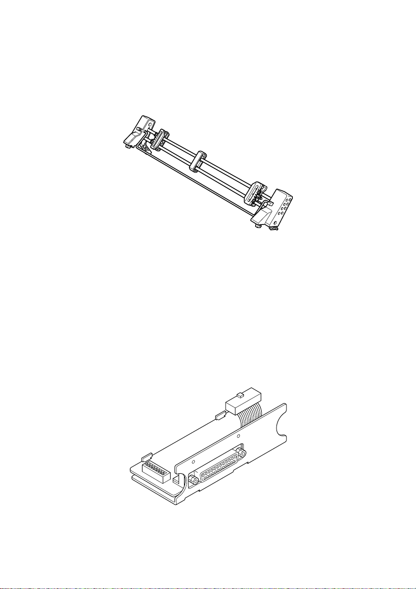
Pull Tractor Unit (PT-15HA) 67
Pull Tractor Unit (PT-15HA)
The pull tractor unit is recommended when printing with multi-part continuous
forms.
Refer to the manual that comes with the pull tractor unit for further details on
installation and operation.
Serial Interface Unit (IS-8H192 and IS-32H768)
Installing the serial interface unit provides serial data communications
capabilities between the printer and your computer.
Page 76

68 Optional Accessories
Specifications (IS-8H192)
Interface RS-232C-level only
Synchronization Asynchronous
Baud rate 150, 300, 600, 1200, 2400, 4800, 9600, 19200 BPS (selectable)
Word length
Start bit 1
Data bits 7 or 8 (selectable)
Parity bit Odd, even, none (selectable)
Stop bits One or more
Signal polarity
Mark Logical 1 (–3V to –15V)
Space Logical 0 (+3V to +15V)
Handshaking DTR, XON/XOFF, ETX/ACK
Data buffer 8 kbytes (standard)
Specifications (IS-32H768)
RS-232C Interface
Synchronization Asynchronous
Baud rate 150, 300, 600, 1200, 2400, 4800, 9600, 19200 BPS (selectable)
Word length
Start bit 1
Data bits 7 or 8 (selectable)
Parity bit Odd, even, none (selectable)
Stop bits One or more
Signal polarity
Mark Logical 1 (–3V to –15V)
Space Logical 0 (+3V to +15V)
Handshaking DTR, XON/XOFF, ETX/ACK
Data buffer 32 kbytes (standard)
RS-422A Interface
Synchronization Asynchronous
Baud rate 150, 300, 600, 1200, 2400, 4800, 9600, 19200 , 38400, 76800 BPS (selectable)
Word length
Start bit 1
Data bits 7 or 8 (selectable)
Parity bit Odd, even, none (selectable)
Stop bits One or more
Signal polarity
Mark Logical 1 (A is –0.2 V or less than B)
Space Logical 0 (A is
Handshaking DTR, XON/XOFF, ETX/ACK
Data buffer 32 kbytes (standard)
+
0.2 V or more than B)
Refer to the manual that comes with the serial interface unit for further details
on installation and operation.
Page 77
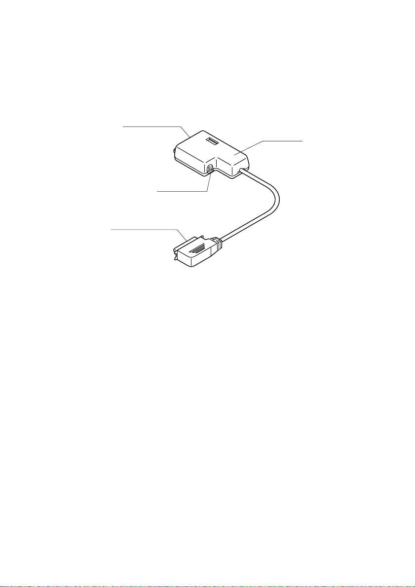
Serial-to-Parallel Converter (SPC-8K) 69
Serial-to-Parallel Converter (SPC-8K)
Connecting the serial-to-parallel converter to the printer’s parallel connector
provides serial data communications capabilities between the printer and your
computer.
Serial connector
Clear button
Parallel connector
Specifications
Interface RS-232C-level
Synchronization Asynchronous
Baud rate 150, 300, 600, 1200, 2400, 4800, 9600, 19200 BPS (selectable)
Word length
Start bit 1
Data bits 7 or 8 (selectable)
Parity bit Odd, even, none (selectable)
Stop bits One or more
Signal polarity
Mark Logical 1 (-3V to -15V)
Space Logical 0 (+3V to +15V)
Handshaking DTR, XON/XOFF, ETX/ACK
Data buffer 8 kbytes (standard)
Dip switch
Refer to the manual that comes with the serial-to-parallel converter for further
details on installation and operation.
Page 78

70
Appendix A: Troubleshooting
This appendix will help you if you experience problems with your printer. It
tells you how to test the printer, how to check system software settings, and how
to adjust the vertical alignment. In addition, there is information on actions to
take for specific problems.
Warning!
The printer uses high voltage. Do not attempt any other r epair or maintenance
except as expressly recommended in this appendix. Unauthorized repair and
maintenance not only exposes you to the danger of electrical shock, it also may
damage your printer and void your warranty.
Testing the printer
There are three different tests you can use: a short test, a long test and a
hexadecimal dump.
Short test
❏ Make sure that paper is loaded in the printer.
❏ Turn the printer off.
❏ While holding down the control panel’s ON LINE button, turn the printer
on.
The short test prints the version number of the software contained in the
printer’s ROM followed by the current EDS settings.
Note:
The short test prints across the entire width of the carriage. Make sure that the
printer is loaded with the widest paper available in order to avoid damage to
the print head and platen.
Page 79

Long test
❏ Make sure that paper is loaded in the printer.
❏ Turn the printer off.
❏ While holding down the control panel’s LINE FEED button, turn the
printer on.
The long test prints seven lines of text and then continues to print the entire
character set for each font and pitch available.
❏ To stop demo printing, turn the printer off.
Note:
● The long test prints across the entire width of the carriage. Make sure that
the printer is loaded with the widest paper available in order to avoid
damage to the print head and platen.
● Since this test can generate many lines of text and gr aphics, it is a good idea
to perform this test only when using continuous fanfold paper rather than
single sheets.
Hexadecimal dump
Hexadecimal dump 71
This procedure prints in hexadecimal format all codes (character codes and
control codes) that are sent to the printer by the computer. The printer does not
execute any control codes (such as 0A - linefeed), it just prints them out. The
hexadecimal dump is useful when you are writing programs for printer control.
❏ Make sure that paper is loaded in the printer.
❏ Turn off the printer.
❏ While holding down the control panel’s FORM FEED button, turn the
printer back on to enter the Hex Dump Mode.
❏ The printer will now print out the hexadecimal values of any data that is
subsequently sent to it from your computer.
❏ T o exit the He x Dump Mode, first press ON LINE to set the printer off-line,
and then turn the printer off.
Page 80

72 Troubleshooting
Adjusting the dot alignment
You may never have to use the procedure described in this section, but after you
have been using your printer for some time you may find that the dots of some
graphics do not align correctly. For example, what should look like:
may come out looking like one of the following:
This is caused when mechanical parts of the printer get out of alignment. This
happens only rarely and you may never experience it at all throughout the life
of the printer. If you do have problems, use the following procedure to correct it.
❏ Make sure that paper is loaded in the printer.
❏ Turn off the printer.
❏ While holding down the control panel’s FORM FEED and ON LINE
buttons, turn the printer back on to enter the Dot Adjustment Mode.
The printer will print something like the following.
or like this
*** DOT ADJUSTMENT SETTING ***
DRAFT
Note that the printer will feed the paper forward and back each time during
this operation so you can view the printout.
0:
❏ If the three lines do not align properly, use FONT to move the middle line
to the left or PITCH to move it to the right.
The above step performs alignment for the Draft printing mode only. You
must make separate adjustments for the HS-DRAFT (LC-1521 only), DDensity/Speed, D-Density P-Graph, NLQ, Quadruple Density, Normal
Density, Plotter Graphics, CRT Graphics I, CRT Graphics II, and Double
Density modes as well.
❏ Press SET/EJECT/PARK to change to another printing mode.
❏ Repeat the above steps for each printing mode, if necessary.
❏ After making changes to adjustments in all the printing modes you want,
press ON LINE to exit the Dot Adjustment Mode and register your
adjustments.
Page 81
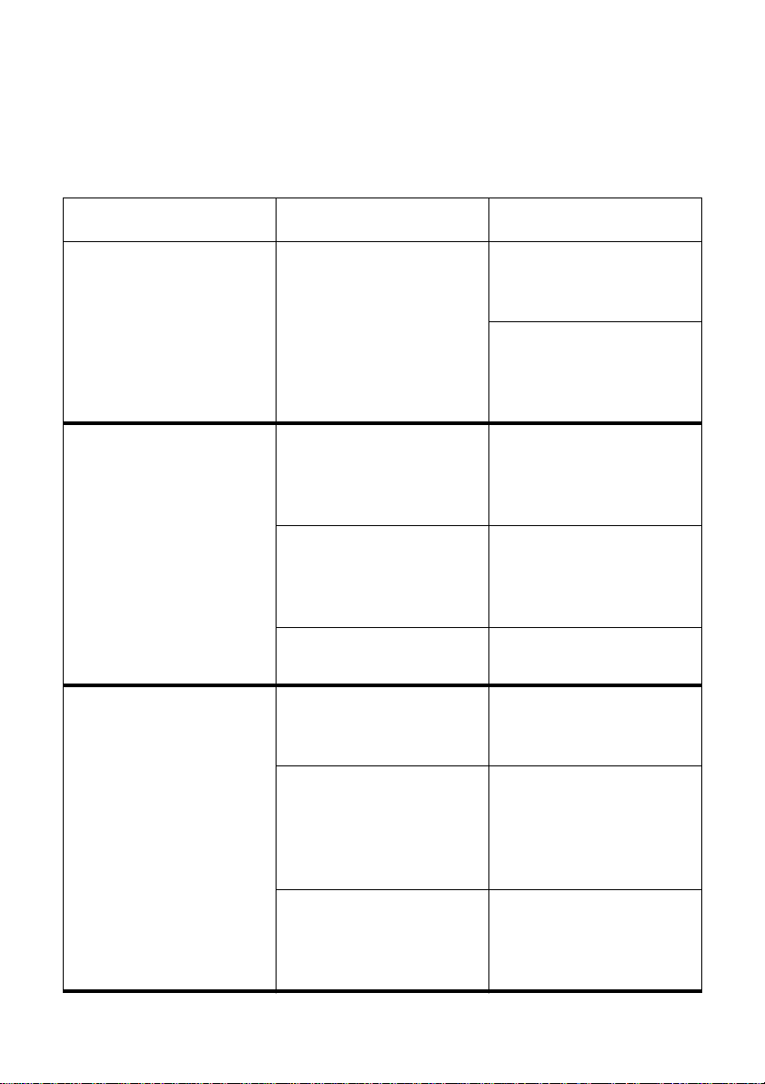
Troubleshooting guide 73
Troubleshooting guide
Use the following table to help track down the causes of problems and to determine the
best solution to deal with them.
Problem Possible Cause Recommended Action
The ON LINE indicator does
not light.
Printer sounds like it is
printing, but it is not.
Printing is weak.
Printer test works, but printer
will not print out data from
the attached computer.
The printer is not receiving
power.
The ribbon is jammed,
twisted, or not set correctly
between the print head and
the print head shield.
The printer is not set up
correctly for the thickness of
paper you are using.
The ribbon is worn out or
“used up.”
Y our application progr am’s or
system software’s printer
selection is wrong.
The computer’s system
software is not set up
properly for the printer or for
the port you are using.
Check whether the power
cord is correctly plugged into
the power outlet.
Check whether the power
outlet is working by
unplugging the printer and
plugging in another device.
Make sure that the ribbon
cassette is installed
correctly.
Set up the printer for the
paper thickness you are
using. See “Adjusting for
paper thickness” on page 63.
Replace the ribbon with a
new one.
Check the printer selection
of your application software.
Check the system software
settings. Check the settings
for LPT1, COM 1, or COM 2
if you are using the optional
serial interface unit.
The interface cable is
connected incorrectly or
damaged.
Check to make sure that the
printer interface cable is
connected correctly. If it is,
try a different cable.
Page 82
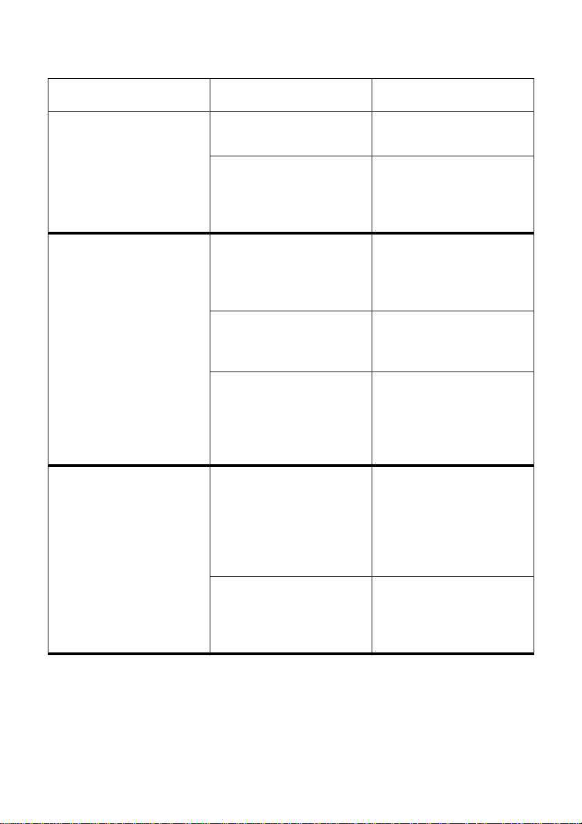
74 Troubleshooting
Problem Possible Cause Recommended Action
Printer does not feed paper
properly.
Line spacing is incorrect. Jamming paper. Set up the printer for the
Lines print over each other. Auto line feed with carriage
Jamming paper. Remove all paper from the
printer and then reload it.
The printer is not set up
correctly for the thickness of
paper being used.
The line spacing or leading
selected in your application
program is wrong.
Auto line feed with carriage
return is enabled.
return is disabled.
Set up the printer for the
paper thickness you are
using. See “Adjusting for
paper thickness” on page 63.
paper thickness you are
using. See “Adjusting for
paper thickness” on page 63.
Choose a different line
spacing or leading setting
from your application.
Use the EDS Mode or User
Setup Utility to disable auto
line feed with carriage return.
See “Switch 4: Auto LF with
CR” on page 32.
Use the EDS Mode or User
Setup Utility to enable auto
line feed with carriage return.
See “Switch 4: Auto LF with
CR” on page 32.
Jamming paper. Set up the printer for the
paper thickness you are
using. See “Adjusting for
paper thickness” on page 63.
Page 83
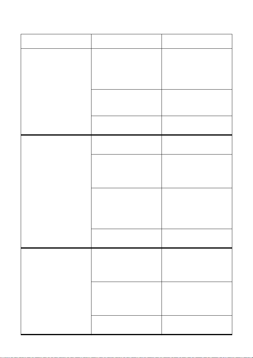
Troubleshooting guide 75
Problem Possible Cause Recommended Action
Incorrect number of lines are
printed on the page.
Text and graphics are
malformed.
Print quality is poor.
Auto line feed with carriage
return is enabled.
The line spacing or leading
selected by your application
program is wrong.
Dot adjustment is not
correct.
The ribbon is worn out or
“used up.”
The printer is not set up
correctly for the thickness of
paper being used.
The printer is not in the Multipart Mode when printing on
multi-part forms with an
original and three to four
copies.
Use the EDS Mode or User
Setup Utility to disable auto
line feed with carriage return.
See “Switch 4: Auto LF with
CR” on page 32 .
Choose a different line
spacing or leading setting
from your application.
See “Adjusting the dot
alignment” on page 72.
Replace the ribbon with a
new one.
Set up the printer for the
paper thickness you are
using. See “Adjusting for
paper thickness” on page 63.
Use the EDS Mode or User
Setup Utility to enter the
Multi-part Mode. See “Switch
6: Multi-Part Mode” on
page 32.
Forms are smudged.
Printing is too dark.
The print head is damaged. Return the printer to your
dealer for repair.
The printer is not set up
correctly for the thickness of
paper being used.
The ribbon is jammed,
twisted, or not set correctly
between the print head and
the print head shield.
Print head shield is damaged
or missing.
Set up the printer for the
paper thickness you are
using. See “Adjusting for
paper thickness” on page 63.
Make sure that the ribbon
cassette is installed
correctly. See “Installing the
ribbon cassette” on page 6.
Return it to your dealer for
repair.
Page 84
76 Troubleshooting
Problem Possible Cause Recommended Action
Printer case is hot. The printer’s air vents are
blocked or obstructed.
Printer makes excessive
noise.
Printer prints past the edge
of the paper.
The front cover is removed. Replace the front cover.
The printer is vibrating. Move any objects that are
Incorrect margin settings
are selected by your
application program.
The paper guide is not
positioned correctly.
The ribbon is jammed,
causing the print head to
jam.
Switch off the printer and let
it cool. Check the air vents
on the bottom of the printer
to see if they are blocked.
Remove the obstruction if
possible. If the problem
persists, return the printer to
your dealer for repair.
touching the printer.
Make sure that the printer is
on a level steady surface.
Choose different margin
settings from your
application program.
Remove the paper and
adjust the position of the
paper guide. Reload the
paper and try printing again.
Make sure that the ribbon
cassette is installed
correctly. See “Installing the
ribbon cassette” on page 6.
Paper is jamming, causing
the print head to jam.
Remove all paper from the
printer and reload it. Try
printing again.
Set up the printer for the
paper thickness you are
using. See “Adjusting for
paper thickness” on page 63.
Page 85
Troubleshooting guide 77
Problem Possible Cause Recommended Action
Left margin moves to the
right during printing.
Some characters are printed
incorrectly.
The paper is not loaded
correctly, causing the print
head to jam.
The ribbon cassette is not
installed correctly, causing
the print head to jam.
The printer is not set up
correctly for the thickness of
paper being used.
Inappropriate settings are
selected by your application
program.
Static electricity caused by
interference from nearby
electrical devices or by lowlevel humidity is affecting
printer operation.
Static electricity caused by
interference from nearby
electrical devices or by lowlevel humidity is affecting
printer operation.
Remove all paper from the
printer and reload it. Try
printing again.
Make sure that the ribbon
cassette is installed
correctly. See “Installing the
ribbon cassette” on page 6.
Set up the printer for the
paper thickness you are
using. See “Adjusting for
paper thickness” on page 63.
Choose different settings in
your application.
Make sure that the printer is
not too close to any devices
with electric motors or try to
raise the humidity level.
Make sure that the printer is
not too close to any devices
with electric motors or try to
raise the humidity level.
Inappropriate settings are
selected by your application
program.
Wires are missing from the
print head.
Choose different settings in
your application.
Return the printer to your
dealer for repair.
Page 86
78 Troubleshooting
Problem Possible Cause Recommended Action
Printer behaves erratically.
Printing suddenly stops.
Automatic Sheet Feeder
does not feed paper.
The interface cable is
connected incorrectly or
damaged.
Static electricity caused by
interference from nearby
electrical devices or by lowlevel humidity is affecting
printer operation.
The EDS Mode setting for
the Automatic Sheet Feeder
is wrong.
Check to make sure that the
printer interface cable is
connected correctly. If it is,
try a different cable.
Make sure that the printer is
not too close to any devices
with electric motors or try to
raise the humidity level.
Enter the EDS Mode and
turn off Switch 4 in Bank A
(see page 31).
Page 87

Checking system software settings in Windows 79
Checking system software settings in Windows
Whenever you have problems printing from a Windows application, you should
check the following four things:
✓ Is the printer you are using set as the default printer?
✓ Is the driver setup correct?
✓ Is the printer you are using correctly selected in your application?
✓ Is the correct port selected?
You should also refer to your Microsoft Windows User’s Guide for other
information that might be helpful. If you still experience problems, consult your
software dealer.
To check the default printer selection
❏ Double-click the Control Panel icon in the Main window.
❏ Double-click the Printers icon.
❏ Check to see that the name of your Star printer is the default printer. If it is
not, double-click on the name of your printer in the list of installed printers.
❏ Click on Close to return to the Control Panel window.
To check the application printer selection
❏ Select Print from the application’ s File menu, and a windo w appears listing
available printers.
❏ Check to see that the name of your Star printer is selected. If it is not, select
it and try printing from your application again.
To check the driver setup
❏ Double-click the Control Panel icon in the Main window.
❏ Double-click the Printers icon.
❏ Double-click on the name of your Star printer in the list of installed
printers.
❏ Click on Setup.
❏ Check resolution, paper source, etc.
❏ Click OK.
❏ Click on Close to return to the Control Panel window.
Page 88

80 Troubleshooting
To check the port
❏ Double-click the Control Panel icon in the Main window.
❏ Double-click the Printers icon.
❏ Double-click on the name of your Star printer in the list of installed
printers.
❏ Click on Connect.
❏ Make sure that your printer cable is connected to the port highlighted in the
list of ports.
If you are using a parallel cable, you will probably be using LPT1. If you are
using the optional serial-to-parallel interface converter or optional serial
interface unit, you should be using COM1 or COM2. Click on the correct
port name.
❏ Click OK.
❏ Click on Close to return to the Control Panel window.
Checking system software settings in MS-DOS
If you are using a parallel cable and cannot print a text file using the MS-DOS
PRINT command, you may have a problem with your AUTOEXEC.BAT file.
Open the file and look for the following line:
MODE LPT1:=COM1 or MODE LPT1:=COM2
These lines indicate you are using a serial cable connection, and so you should
delete them, save the AUTOEXEC.BAT file, reboot and try printing again.
Of course, if you are having problems printing with the optional serial-to-
parallel converter or optional serial interface unit, you should conversely check
to make sure that one of the above lines is included in your AUTOEXEC.BAT
file. The file must also contain information on parameter settings. For details,
see the user’s manual that comes with the optional serial-to-parallel interface
converter or optional serial interface unit.
If the above is not the problem or if you make the above changes and still
experience problems printing using the MS-DOS PRINT command, refer to
your MS-DOS Users’ Guide or consult your software dealer.
If you are successful in printing using the MS-DOS PRINT command but
cannot print from an application, check to see what printer driver is selected in
the application. See “Setting up for printing with MS-DOS” on page 61. If this
does not help, consult your software dealer.
Page 89

Appendix B: Specifications
Printing System Serial Impact Dot-Matrix
Printing Speed Pitch Draft (cps/dpi) NLQ (cps/dpi)
LC-1521
LC-1511 Pica (10 cpi) 225/120H 56/240H
Print Direction Draft: Bi-directional logic seeking
Print Head Number of pins: 9
Line Spacing 1/6
Character Matrix Pitch Draft NLQ
LC-1521
LC-1511 Pica (10 cpi) 9 × 11H 18 × 23H
Environment Operating temperature: 41°F to 95°F (5°C to 35°C)
Pica (10 cpi)
Elite (12 cpi) 360/120H 90/240H
Condensed pica (17 cpi) 255/240H 127/240H
Condensed elite (20 cpi) 300/240H 150/240H
Elite (12 cpi) 270/120H 67/240H
Condensed pica (17 cpi) 191/240H 95/240H
Condensed elite (20 cpi) 225/240H 112/240H
H: half-dot
NLQ: Uni-directional/ bi-directional logic seeking
Bit-Image: Uni-directional/ bi-directional logic seeking
Life: 200 million dots/pin (Normal Mode)
″
, 1/8
″
7/72″, n/72″, n/216″: software
Pica (10 cpi)
Elite (12 cpi) 9 × 9H 18 × 19H
Condensed pica (17 cpi) 9 × 11H 18 × 12H
Condensed elite (20 cpi) 9 × 9H 18 × 10H
Elite (12 cpi) 9 × 9H 18 × 19H
Condensed pica (17 cpi) 9 × 11H 18 × 12H
Condensed elite (20 cpi) 9 × 9H 18 × 10H
Storage temperature: –22°F to 149°F (–30°C to 65°C)
Operating humidity: 30% to 80% (non-condensing)
Storage humidity: 20% to 90% (non-condensing)
300/120H (Normal)
400/90H (HS)
(selectable)
(selectable)
100 million dots/pin (Multi-Part Mode)
9 × 11H (Normal)
9 ×8H (HS)
18 × 23H
75/240H
81
Page 90

82 Specifications
Paper Cut-sheet (manual feeding)
Paper width: 7″ to 16.54″ / 178 to 420 mm
Paper length: 5.5″ to 14″ / 140 to 356 mm
Paper thickness: 0.00276″ to 0.00472″ / 0.07 to 0.12 mm
Paper weight: 14 to 24 lbs. / 52 to 90 g/m2 / 45 to 77 kg
Cut-sheet (with optional automatic sheet feeder)
Paper size: B5, A4, LT, B4, A3, Legal
Paper thickness: 0.00315″ to 0.00472″ / 0.08 to 0.12 mm
Paper weight: 16 to 24 lbs. / 60 to 90 g/m2 / 52 to 77 kg
Hopper: 50 sheets of 64 g/m
30 sheets of 80 g/m
Stacker: 10 sheets
Fanfold (with push tractor feeder)
Paper width: 4″ to 16.5″ / 101.6 to 419 mm
Paper thickness: 0.00276″ to 0.00433″ / 0.07 to 0.11 mm (one-ply)
0.01378″ / 0.35 mm maximum (total thickness of
multi-ply paper, non-carbon)
Paper weight: 14 to 22 lbs. / 52 to 82 g/m2 / 45 to 70 kg (one-ply)
11 to 14 lbs. / 40 to 52 g/m2 / 34 to 45 kg (multi-ply)
Copies: Original + 1 or 2 (Normal Mode)
Original + 3 or 4 (Multi-Part Mode)
* Multi-Part Mode is recommended when using
optional pull tractor unit.
Fanfold (with optional pull tractor feeder)
″
Paper width: 4
to 16.0″ / 101.6 to 406 mm
Paper thickness: 0.00276″ to 0.00433″ / 0.07 to 0.11 mm (one-ply)
0.01378″ / 0.35 mm maximum (total thickness of
multi-ply paper, non-carbon)
Paper weight: 14 to 22 lbs. / 52 to 82 g/m2 / 45 to 70 kg (one-ply)
11 to 14 lbs. / 40 to 52 g/m2 / 34 to 45 kg (multi-ply)
Copies: Original + 1 or 2 (Normal Mode)
Original + 3 or 4 (Multi-Part Mode)
Labels
Backing sheet: 4.5″ to 16.5″ / 114 to 419 mm
Thickness
Backing sheet: 0.00268″ to 0.0035″ / 0.07 to 0.09mm
Total: 0.0075″ / 0.19mm max.
Emulation Standard Mode: EPSON ESC/P (9-pin)
IBM Mode: Proprinter III
Interface Standard: Centronics parallel
Option: RS-232C/RS-422 serial
2
2
Page 91

Ribbon Type On-carriage, dedicated
Monochrome (Y9WH), Black only
Ribbon Life 2.5 million characters (Draft 10 cpi)
Dimensions and Weight Width: 23.2″ / 590 mm
Depth: 13.9″ / 355 mm
Height: 7.3″ / 186 mm
Weight: 18.3 lbs. / 8.3 kg
Power Supply 120V AC +10%/–17%, 230V AC +14%/–13%; 50/60Hz
(depending on country of purchase)
Power Consumption
LC-1521 11W during standby / 50W during ASCII draft printing
LC-1511 9W during standby / 30W during ASCII draft printing
Options PT-15HA Pull Tractor Unit
SF-15HA Single-Bin Automatic Sheet Feeder
IS-8H192 Serial Interface Unit
IS-32H768 Serial Interface Unit
SPC-8K Serial-To-Parallel Converter
83
Page 92
84
Appendix C: Interface Pin Outs
Parallel Interface
Pin Name Function
1 STROBE Goes low for ≥0.5µs when active.
2 DATA0 These signals represent information for the 1st through 8th bit of parallel data,
3 DATA1
4 DATA2
5 DATA3
6 DATA4
7 DATA5
8 DATA6
9 DATA7
10 ACK 10µs low to acknowledge receipt of data.
11 BUSY Printer sets line low when ready to receive data.
12 PAPER High when paper runs out.
13 SELECT High when printer is on-line.
14
15 Not used.
16 SIGNAL GND Signal ground
17 CHASSIS Chassis ground (isolated from signal ground)
18 +5V +5V DC output from printer
19 - 30 GND Twisted pair ground return
31 RESET Printer is reset when this signal goes low.
32 ERROR Low when printing cannot continue due to error.
33 EXT GND External ground
34 - 35 Not used
36 SELECT IN Printer ignores this signal
AFXT Printer ignores this signal
respectively. Each signal is HIGH when data is logical 1, and LOW when logical
0.
Optional Serial Interface (IS-8H192 and SPC-8K)
Pin Name Function
1 GND Printer chassis ground
2 TXD Data from printer
3 RXD Data to printer
4 RTS Always space
5 CTS Space when computer is ready to send data. Printer ignores this signal.
6 Not used.
7 GND Signal ground
8 - 10 Not used.
11 RCH Printer sets line to space when ready to receive data. Same signal as Pin 20.
12 - 19 Not used.
20 DTR Printer sets line to space when ready to receive data.
21 - 25 Not used.
Page 93
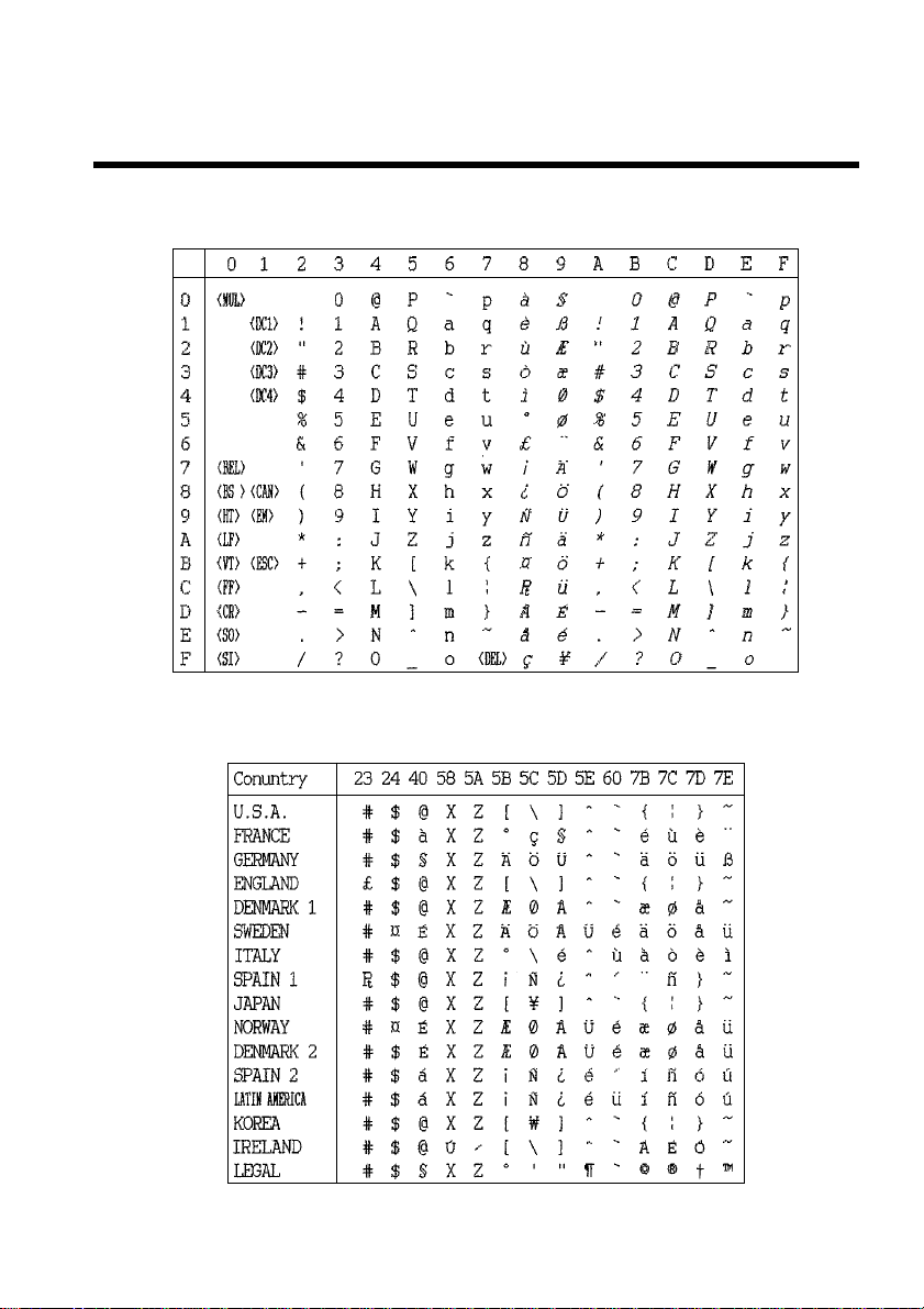
Appendix D: Character Sets
Standard Italic Character Set
International Character Set
The character codes shown in the table are hexadecimal.
85
Page 94
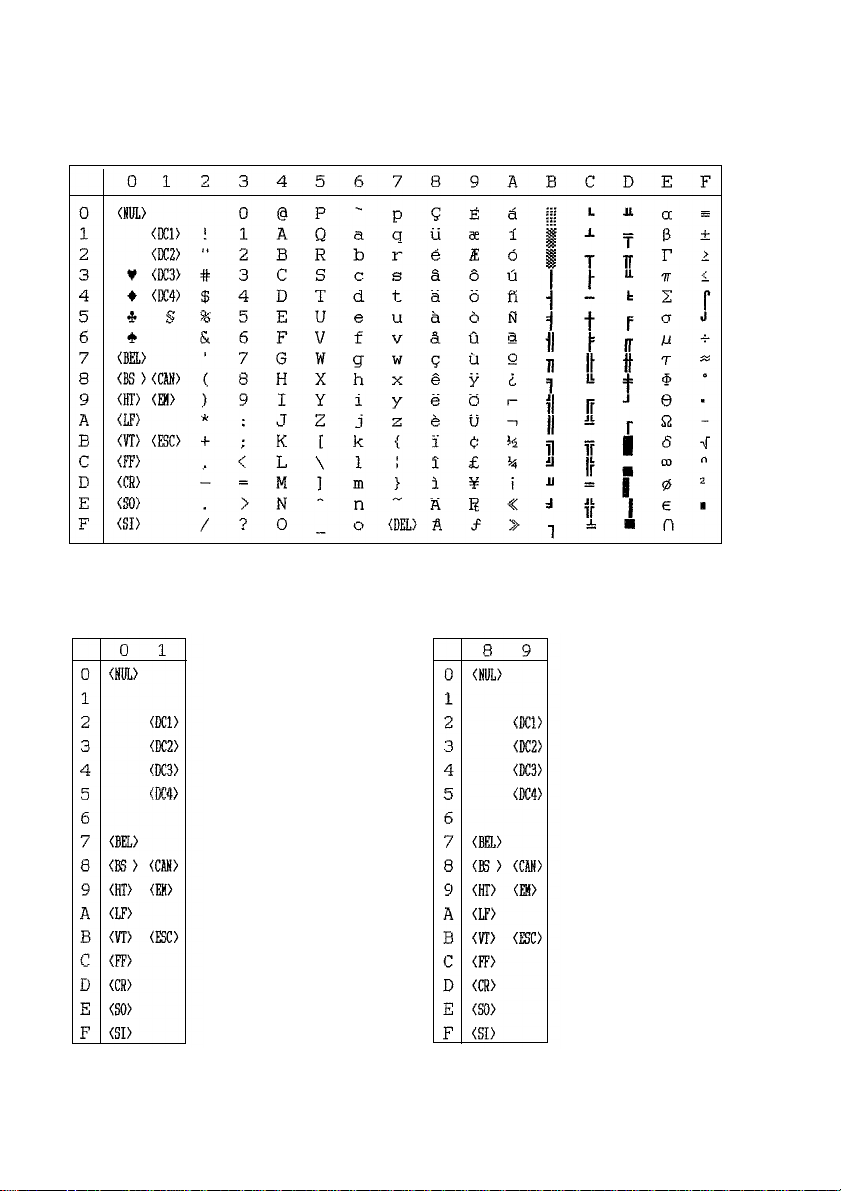
86 Character Sets
IBM Character Set #2
Code Page #437 (IBM-PC)
Character Set #1
Other characters are the same as those for Character Set #2.
Page 95
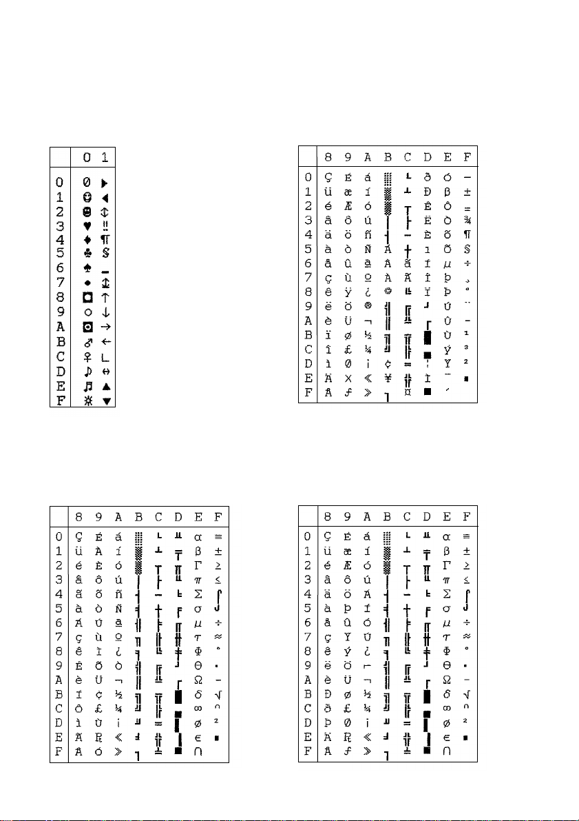
87
Code Page #860
Portuguese
Other characters are the same as those for
Code Page #437.
Code Page #861
Icelandic
Other characters are the same as those for
Code Page #437.
IBM Special Character Set
The following characters can be printed
using the <ESC> ^ command.
Code Page #850
Multi-lingual
Other characters are the same as those for
Code Page #437.
Page 96
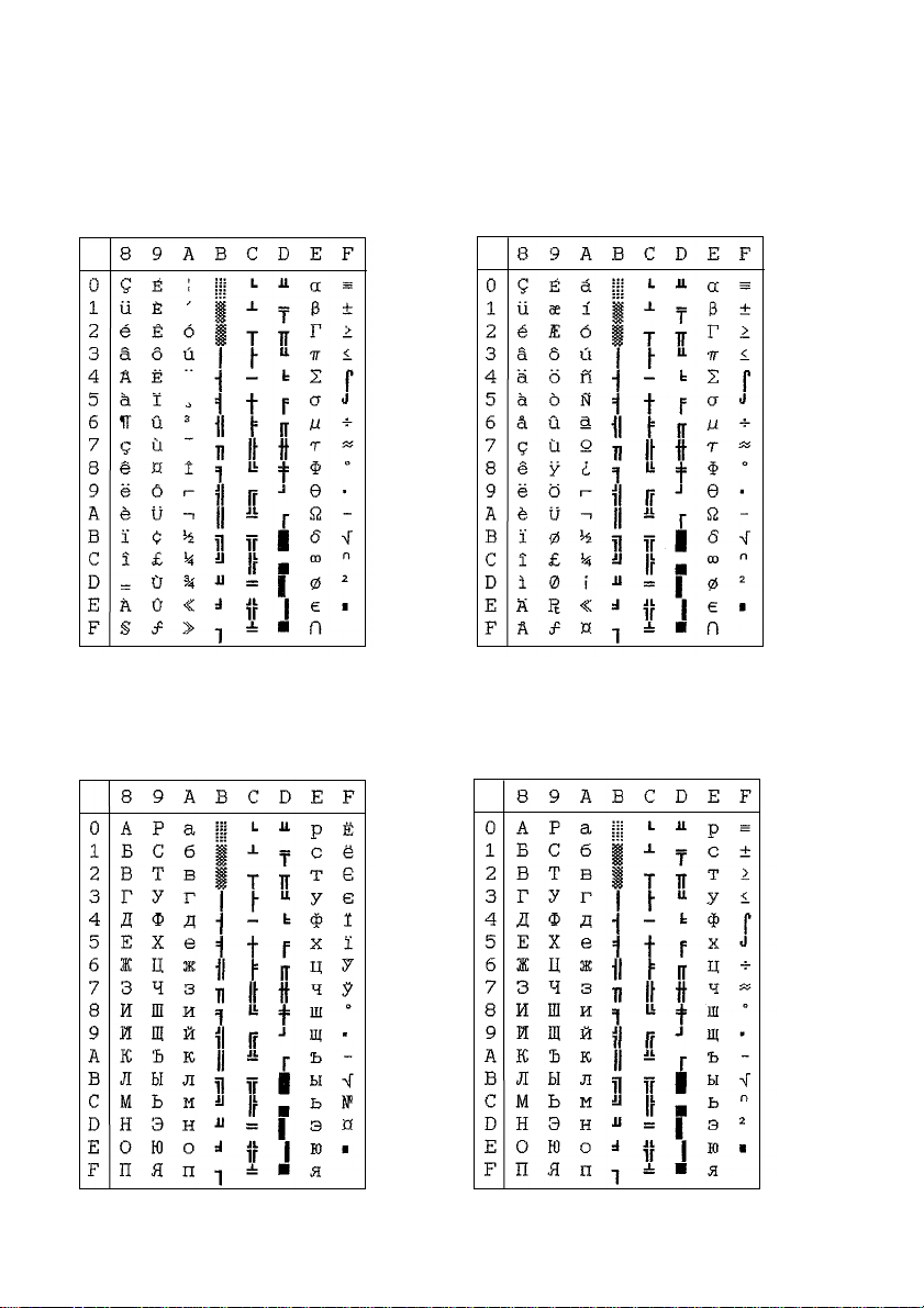
88 Character Sets
Code Page #863
Canadian French
Other characters are the same as those for
Code Page #437.
Code Page #866
Russian
Other characters are the same as those for
Code Page #437.
Code Page #865
Nordic
Other characters are the same as those for
Code Page #437.
Code Page #3840
IBM-Russian
Other characters are the same as those for
Code Page #437.
Page 97
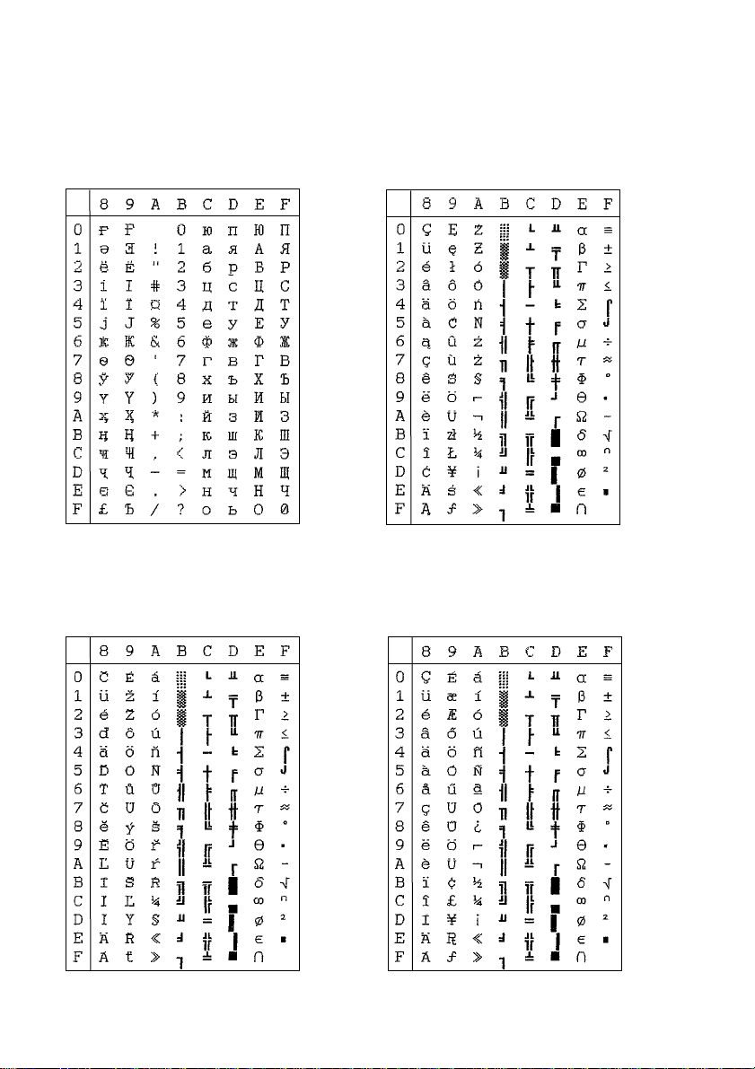
89
Code Page #3841
Gost-Russian
Other characters are the same as those for
Code Page #437.
Code Page #3844
CS2
Other characters are the same as those for
Code Page #437.
Code Page #3843
Polish
Other characters are the same as those for
Code Page #437.
Code Page #3845
Hungarian
Other characters are the same as those for
Code Page #437.
Page 98
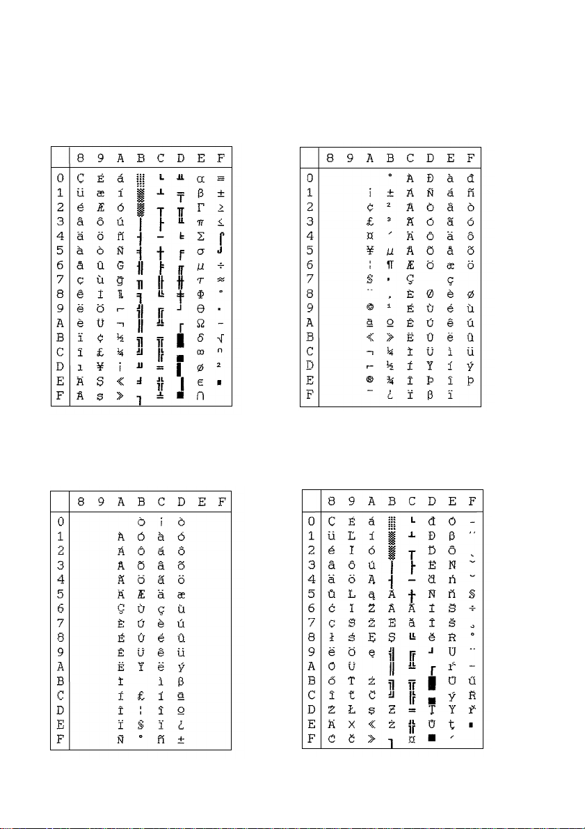
90 Character Sets
Code Page #3846
Turkish
Other characters are the same as those for
Code Page #437.
Code Page #3848
Brazil-ABICOMP
The other characters are the same as in
code page #437.
Code Page #3847
Brazil-ABNT
Other characters are the same as those for
Code Page #437.
Code Page #852
Latin-2
Other characters are the same as those for
Code Page #437.
Page 99
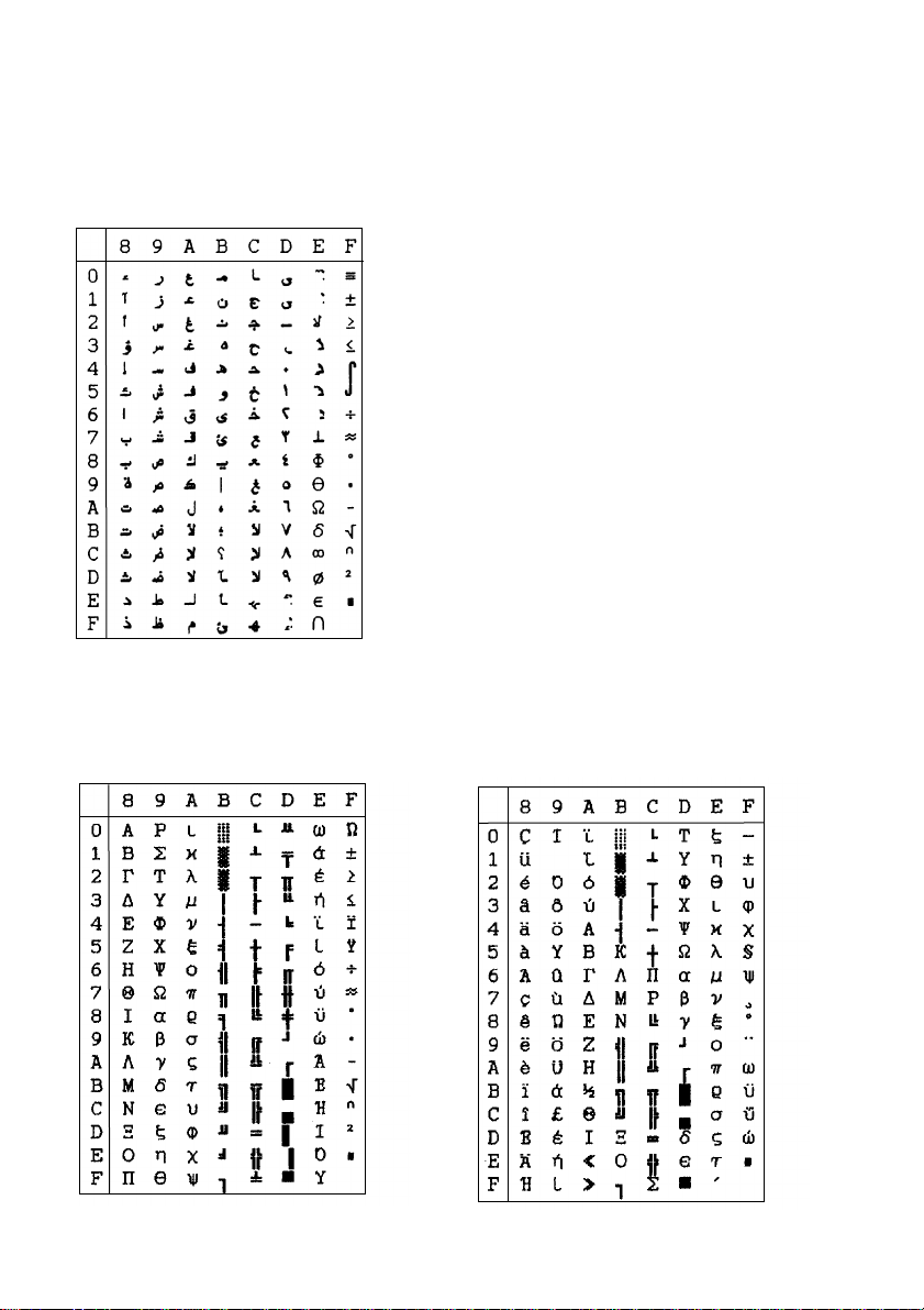
Code Page #1001
Arabic
Other characters are the same as those for
Code Page #437.
91
Code Page #737
Greek
Other characters are the same as those for
Code Page #437.
Code Page #851
Greek
Other characters are the same as those for
Code Page #437.
Page 100
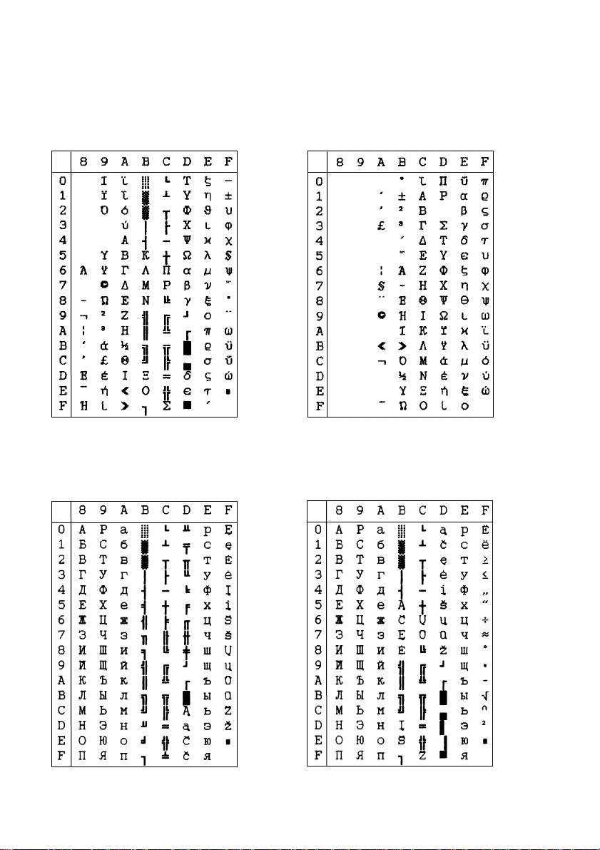
92 Character Sets
Code Page #869
Greek
Other characters are the same as those for
Code Page #437.
Code Page #2001
Lithuanian-KBL
Other characters are the same as those for
Code Page #437.
Code Page #928
Greek
Other characters are the same as those for
Code Page #437.
Code Page #772
Lithuanian
Other characters are the same as those for
Code Page #437.
 Loading...