

Page 1

DOT MATRIX PRINTER
NX-1000SERIES
LC-10SERIES
TECHNICAL MANUAL
[ NINTH EDITION ]
Page 2

NOTICE
• All rights reserved. Reproduction of any part of this manual
in any form whatsoever, without STAR’s express permission is forbidden.
• The contents of this manual are subject to change without
notice.
• All efforts have been made to ensure the accuracy of the
contents of this manual at the time of going to press.
However, should any errors be detected, STAR would
greatly appreciate being informed of them.
• The above notwithstanding, STAR can assume no respon-
sibility for any errors in this manual.
© Copyright 1987 Star Micronics Co.,Ltd.
Page 3
INTRODUCTION
This manual describes dot matrix printers as shown below.
It is intended for use as a reference for periodic inspections and maintenance procedures.
This manual is prepared for use at a technical level and not for the general user.
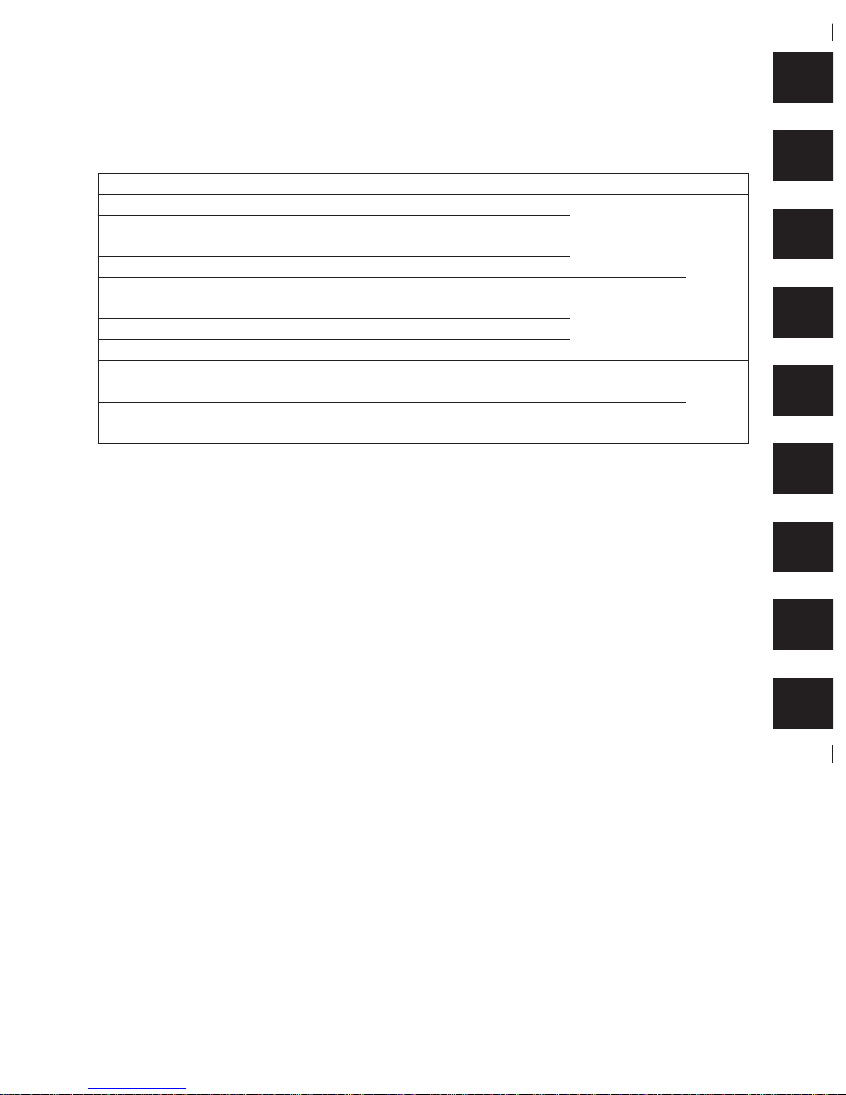
Model Interface Mono/Colour Destination Ver.
NX-1000MULTI-FONT PRINTER Parallel Type Monochrome
NX-1000CMULTI-FONT PRINTER Commodore Type Monochrome
NX-1000COLOUR PRINTER Parallel Type Colour
NX-1000C COLOUR PRINTER Commodore Type Colour
LC-10 MULTI-FONT PRINTER Parallel Type Monochrome
LC-10CMULTI-FONT PRINTER Commodore Type Monochrome
LC-10 COLOUR PRINTER Parallel Type Colour
LC-10C COLOUR PRINTER Commodore Type Colour
NX-1000 II MULTI-FONT PRINTER Parallel Type Monochrome
LC-10 II MULTI-FONT PRINTER Parallel Type Monochrome
• This manual is divided into the following sections:
Chapter 1 General Specifications
Chapter 2 Theory of Operation
Chapter 3 Adjustments
Chapter 4 Parts Replacement
Chapter 5 Maintenance and Lubrication
Chapter 6 Troubleshooting
Chapter 7 Parts List (Ver. 1 and Ver. 1.5)
Chapter 8 Parts List (Ver. 2)
Appendix Explanation of Principle ICs
• First edition : Nov. 1987 Only Monochrome Type
Second edition : Mar. 1988 Add Colour Type
Third edition : Dec. 1988 Add Ver. 1.5 of Parallel Type
Fourth edition : Jul. 1989 Add NX-1000 II and LC-10 II (Ver. 2 of Parallel Type)
Fifth edition : Apr. 1991
Sixth edition : Aug. 1993
Seventh edition :Sep. 1995
Eighth edition :Apr. 1996
Ninth edition :Aug. 1997
Except for
European market
For European
Market
For American
and Asian market
For European and
Pacific market
Ver. 1
and
Ver. 1.5
Ver. 2
1
2
3
4
5
6
7
8
APP.
Page 4

CHAPTER 1
GENERAL SPECIFICATIONS
1. General Specifications .........................................................................................3
1-1. Parallel Type............................................................................................................ 3
1-2. Commodore Type.................................................................................................... 4
2. External Appearance and Composition .............................................................. 7
2-1. Names of Parts........................................................................................................ 7
2-2. DIP switch settings ................................................................................................. 9
3. Connector Signals .............................................................................................. 11
3-1. Parallel Interface ................................................................................................... 11
3-2. Commodore Interface........................................................................................... 12
1
2
3
4
5
6
7
8
A
Page 5

– 2 –
GENERAL SPECIFICATIONS
Page 6
– 3 –
GENERAL SPECIFICATIONS
1. General Specifications
1-1. Parallel Type
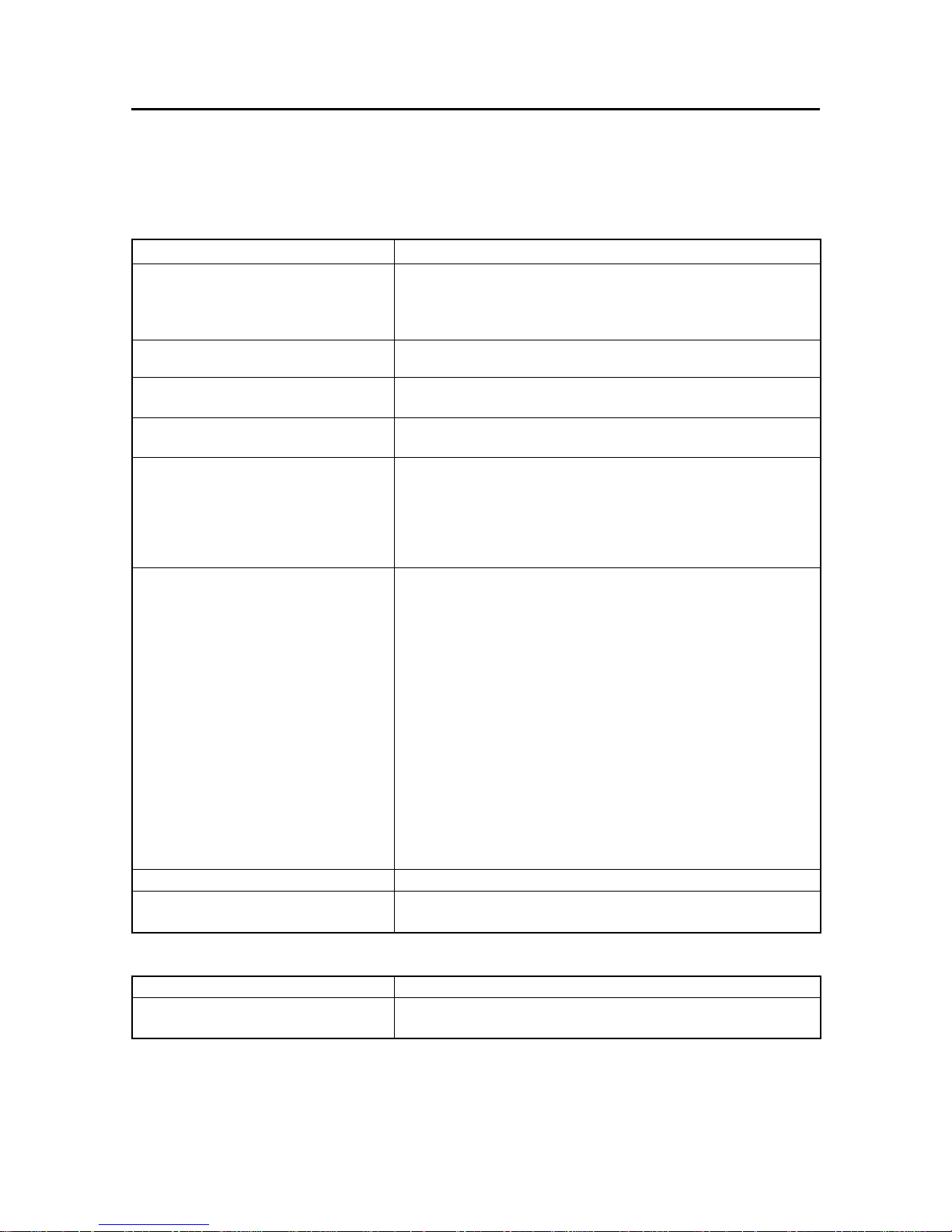
Printing
Printing method Serial impact dot matrix
Printing speed 120 characters per second (in Draft pica for Ver. 1 and Ver. 1.5)
30 characters per second (in NLQ pica for Ver. 1 and Ver. 1.5)
150 characters per second (in Draft pice for Ver. 2)
38 characters per second (in NLQ pica for Ver. 2)
Data buffer 4K bytes (for monochrome type), 8K byte (for colour type) when not used for
download characters. 1-Line buffer when using download
Paper feed 2.7 inches/second (during page feed)
Friction and push-tractor feed
Printing direction Draft: bi-directional or unidirectional (selectable), logic seeking
NLQ and graphics: unidirectional, logic seeking
Character set
Standard character set 96 ASCII characters
IBM character set 244 characters (ASCII,international characters, symbols, block graphics)
Downloadable characters Max.192 (draft) or 78 (NLQ)
International character sets 14 sets (USA, France, Germany, England, Denmark I, Denmark II, Sweden,
Italy, Spain I, Spain II, Japan, Norway, Latin America, Denmark/Norway
Dot matrix size
Character matrix 9 × 9 dots (Draft pica)
18 × 23 dots (Courier and Orator pica)
18 × 18 dots (Sanserif pica,elite)
12 × 11 dots (IBM block graphics,pica)
18 × 19 dots (Courier and Orator elite)
18 × 12 dots (Condensed pica)
18 × 10 dots (Condensed elite)
Bit-image graphic 8 × 480 dots at 60 dpi (Single density)
9 × 480 dots at 60 dpi (Single density)
8 × 576 dots at 72 dpi (Plotter mode)
8 × 640 dots at 80 dpi (CRT I)
8 × 720 dots at 90 dpi (CRT II)
8 × 960 dots at 120 dpi (Double density)
9 × 960 dots at 120 dpi (Double density)
8 × 960 dots at 120 dpi (High speed)
8 × 1920 dots at 240 dpi (Quadruple density)
Line spacing 1/6 inch standard 1/8, n/72, or n/216 inch programmable
Column width 80, normal pica 96, normal elite
137, condensed pica 160, condensed elite
Paper
Single sheets 5.5 ~ 8.5 inches wide 0.07 ~ 0.10 mm thick
Fanfold paper 4 ~ 10 inches wide 0.07 ~ 0.10 mm thick (single-ply)
Max, 0.28mm thick (3-ply)
Page 7
– 4 –
GENERAL SPECIFICATIONS
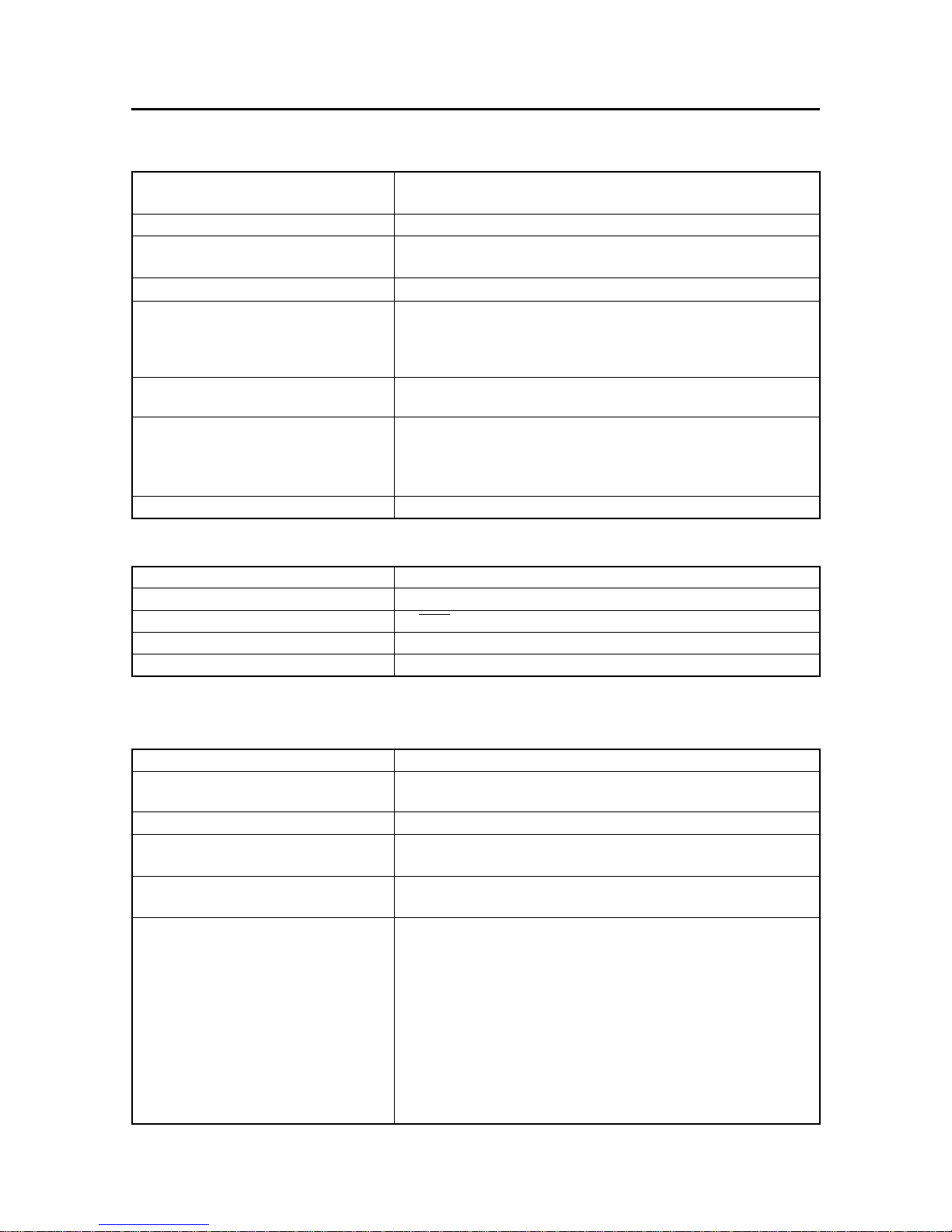
Printer
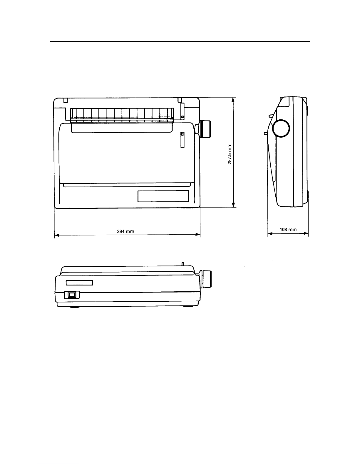
Dimensions Height 108 mm (4.3 inches) Width 384 mm (15.1 inches)
Depth 287.5 mm (11.3 inches)
Weight 4.7 kg (10.3 pounds)
Power 120 VAC±10%, 60Hz. 220 VAC±10%, 50/60Hz.
240 VAC±10%, 50/60Hz.
Power consumption Typ. 30W, Max. 60W
Environment Operating temperature: 5 to 40°C (41 to 104°F)
Operating humidity: 10 to 80%, non condensation
Storage temperature: –30 to 65°C (–22 to 149°F)
Storage humidity: 10% to 95% (at 40°C) (no condensation)
Print head 9 Pins
Life: 200 million dots
Ribbon Fabric ribbon cartridge
Monochrome type ........................... Black
Colour type ..................................... Black/cyan/magenta/yellow
Life: 1 million draft characters
Option Automatic sheet feeder
Parallel interface
Interface Centronics-compatible
Synchronization By external supplied strobe pulses
Handshaking By ACK or BUSY signals
Logic level TTL
Connector 57-30360 Amphenol
1-2. Commodore Type
Printing
Printing method Serial impact dot matrix
Print speed 120 characters per second (in Draft pica)
30 characters per second (in NLQ pica)
Data buffer 1-line buffer
Paper feed 2.7 inches/second (during page feed)
Friction and push-tractor feed
Printing direction Draft: bi-directional or unidirectional (selectable), logic seeking
NLQ and graphics: unidirectional, logic seeking
Commodore character sets
Standard graphics Upper-case letters, digits, punctuation and symbols, graphic characters
Standard business Lower- and upper-case letters, digits, punctuation and symbols, graphic charac-
ters
DIN graphics Upper-case letters, international letters, digits, punctuation and symbols, graphic
characters
DIN business Lower- and upper-case letters, international letters, digits, punctuation and
symbols, graphic characters
Downloadable characters Max. 192 (draft) or 80 (NLQ)
International characters sets 10 sets (England, USA, France, Germany, Denmark I, Denmark II, Sweden I,
Italy, Spain, Sweden II)
Page 8
– 5 –
GENERAL SPECIFICATIONS
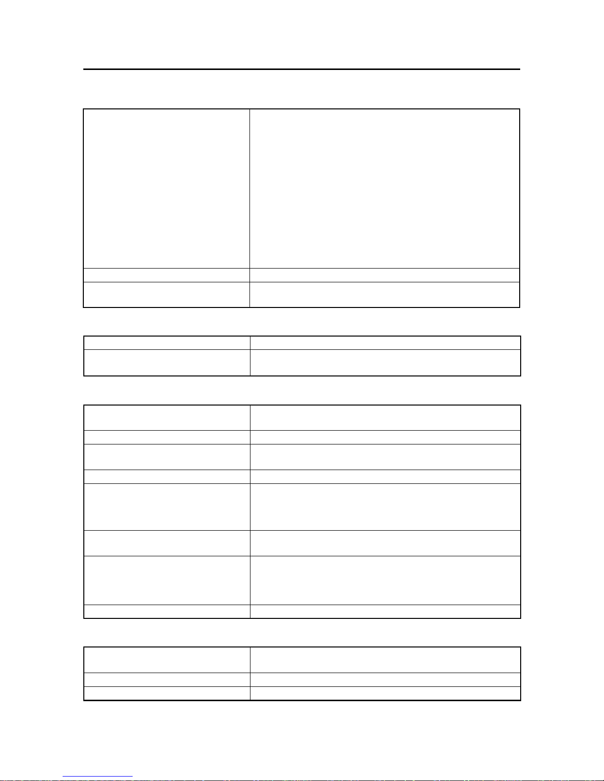
Printing
Dot matrix size
Character matrix 9 × 9 dots (Draft pica)
18 × 23 dots (Courier and Orator pica)
18 × 18 dots (Sanserif pica,elite)
7 × 11 dots (Block graphics,pica)
18 × 19 dots (Courier and Orator elite)
18 × 12 dots (Condensed pica)
18 × 10 dots (Condensed elite)
Bit-image graphic 7 × 480 dots at 60 dpi (Single density)
8 × 480 dots at 60 dpi (Single density)
7 × 960 dots at 120 dpi (Double density)
8 × 960 dots at 120 dpi (Double density)
8 × 960 dots at 120 dpi (High speed)
8 × 1920 dots at 240 dpi (Quadruple density)
Line spacing 1/6 inch standard 1/8, n/72, or n/216 inch programmable
Column width 80, normal pica 96, normal elite
137, condensed pica 160, condensed elite
Paper
Single sheets 5.5 ~8.5 inches wide 0.07 ~ 0.10 mm thick
Fanfold paper 4 ~ 10 inches wide 0.07 ~ 0.10 mm thick (single-ply)
Max. 0.28mm thick (3 ply)
Printer
Dimensions Height 108 mm (4.3 inches) Width 384 mm (15.1 inches)
Depth 287.5 mm (11.3 inches)
Weight 4.7 kg (10.3 pounds)
Power 120 VAC±10%, 60Hz. 220 VAC±10%, 50/60Hz.
240 VAC±10%, 50/60Hz.
Power consumption Typ. 30W, Max. 60W
Environment Operating temperature: 5 to 40°C (41 to 104°F)
Operating humidity: 10 to 80%, no condensation
Storage temperature: –30 to 65°C (–22 to 149°F)
Storage humidity: 10% to 95% (at 40°C) (no condensation)
Print head 9 Pins
Life: 200 million dots
Ribbon Fabric ribbon cartridge
Monochrome type ........................... Black
Colour type ..................................... Black/blue/red/yellow
Life: 1 million draft characters
Option Automatic sheet feeder
Commodore interface
Interface Serial mode, for Commodore computers
Synchronization By external supplied clock (synchronous serial)
Logic level TTL
Connector 6-pin DIN
Page 9
– 6 –
GENERAL SPECIFICATIONS
Fig. 1-1 External Dimensions
Page 10

– 7 –
GENERAL SPECIFICATIONS
2. External Appearance and Composition
2-1. Names of Parts
Fig. 1-2 Front and rear views of the printer
Page 11
– 8 –
GENERAL SPECIFICATIONS
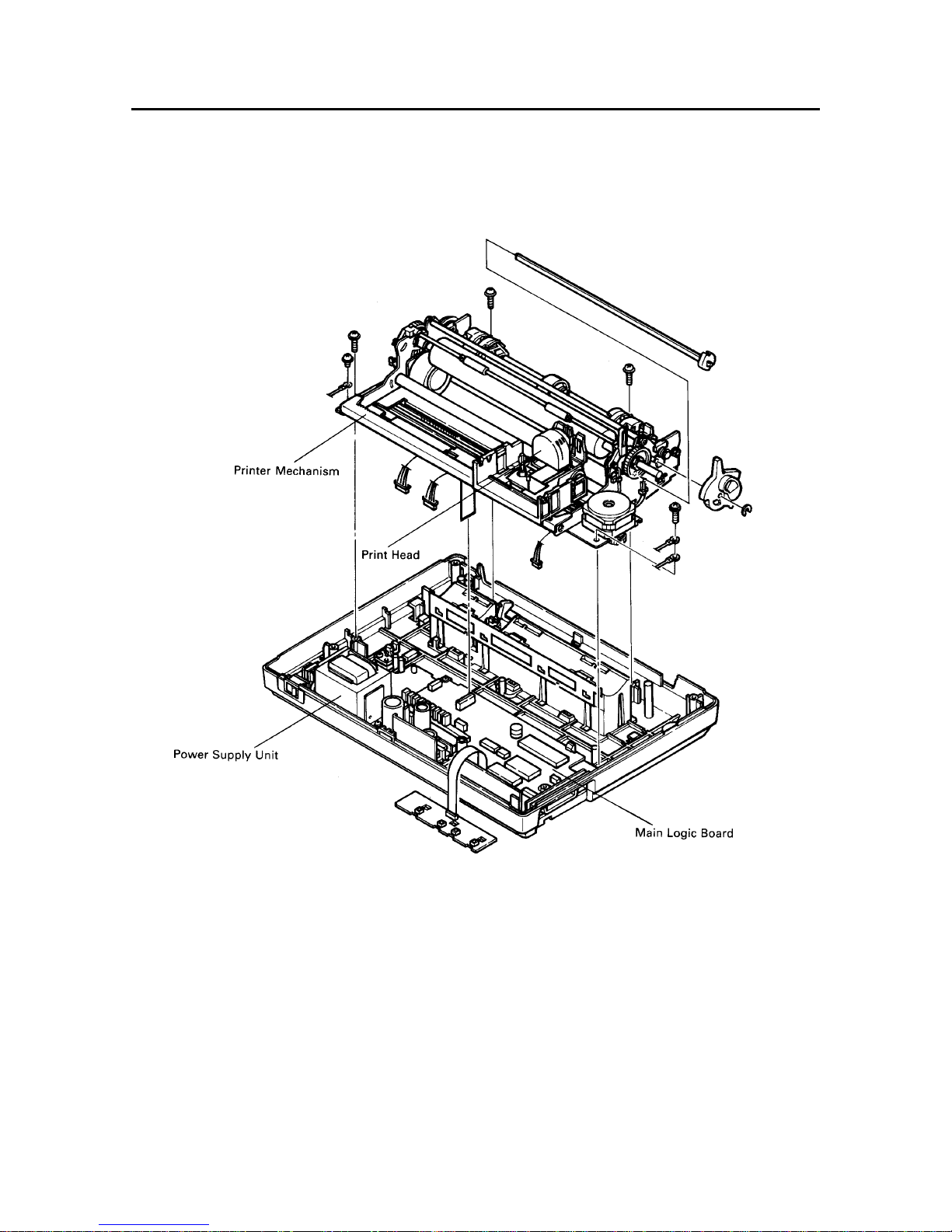
Fig. 1-3 Diagram of Internal Composition
Page 12
– 9 –
GENERAL SPECIFICATIONS
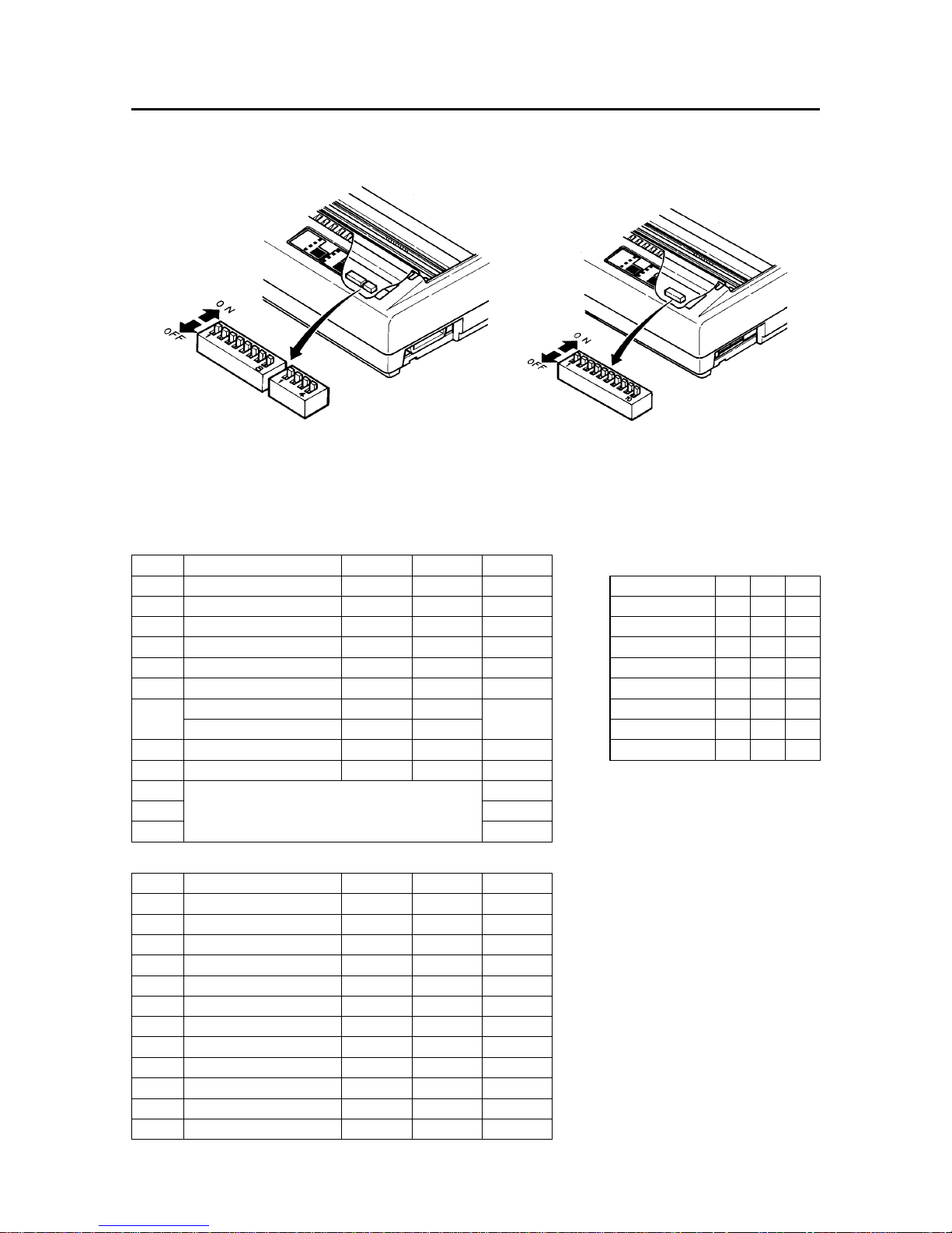
2-2. DIP Switch Settings
Parallel Type Commodore Type
Fig. 1-4 The DIP Switch is located under the Printer Cover
2-2-1. Parallel Type
Switch Function ON OFF Factory
1-1 Page length 11 inches 12 inches ON
1-2 Auto CR Yes No ON
1-3 Orator lower case Small caps Lower case ON
1-4 Auto sheet feeder Inactive Active ON
1-5 Paper-out detector Enabled Disabled ON
1-6 Printer mode Standard IBM ON
Character set (Std. Mode) Italics Graphics
Character set (IBM Mode) Set #2 Set #1
1-8 Auto LF No Yes ON
2-1 Usage of RAM Buffer Download ON
2-2 ON
2-3 International character set (See right) ON
2-4 ON
International character sets:
Country 2-2 2-3 2-4
U.S.A. ON ON ON
France OFF ON ON
Germany ON OFF ON
England OFF OFF ON
Denmark I * ON ON OFF
Sweden OFF ON OFF
Italy ON OFF OFF
Spain I OFF OFF OFF
* Denmark/Norway when switches 1-6
and 1-7 are both OFF.
A. Except for U.S.S.R. market
1-7 ON
Switch Function ON OFF Factory
1-1 Page length 11 inches 12 inches ON
1-2 Auto CR Yes No ON
1-3 Character set Standard IBM ON
1-4 Auto sheet feeder Inactive Active ON
1-5 Paper-out detector Enabled Disabled ON
1-6 Printer mode Standard IBM ON
1-7 Character set Set #1 Set #2 ON
1-8 Auto LF No Yes ON
2-1 Usage of RAM Buffer Download ON
2-2 Italic OFF ON ON
2-3 ESC 4/ESC 5 (*1) Italic MSB ON
2-4 Not used — — ON
*1 The switch 2-3 is valid only in the standard printer mode.
B. For U.S.S.R. market
Page 13
– 10 –
GENERAL SPECIFICATIONS
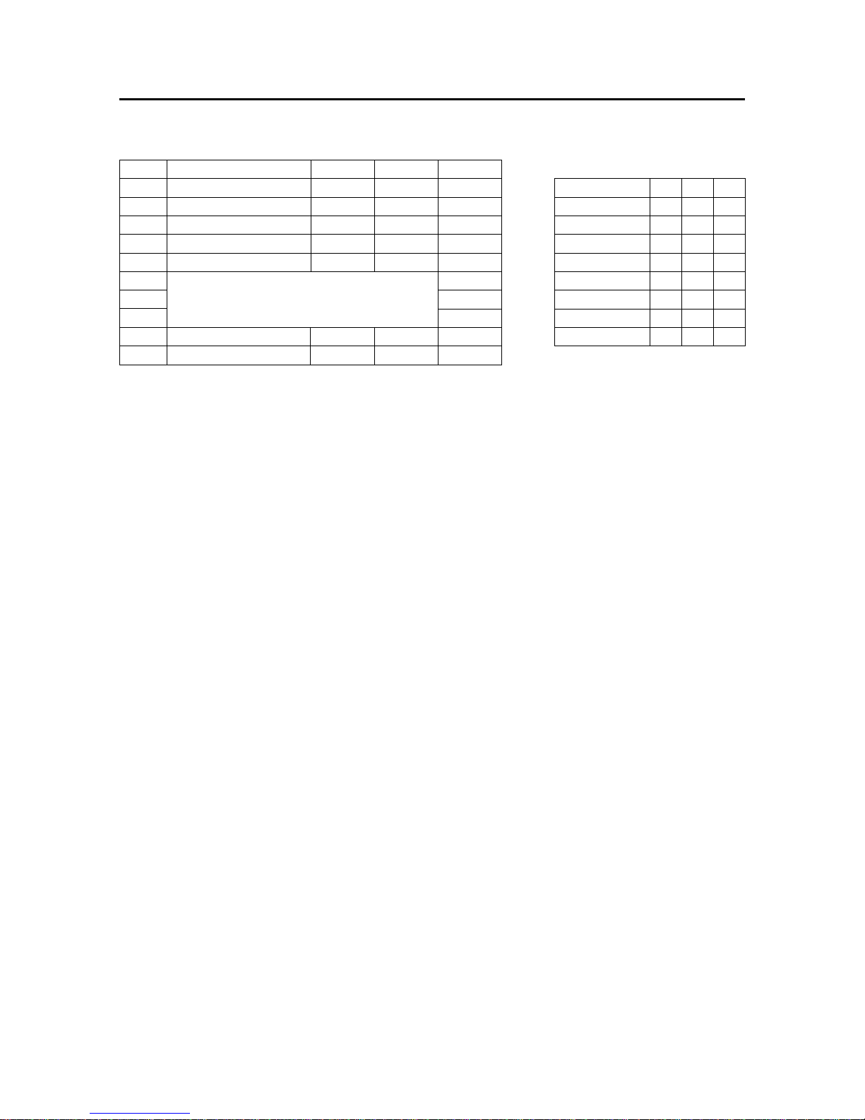
2-2-2. Commodore Type
Switch Function ON OFF Factory
1-1 Auto LF Yes No ON
1-2 Paper out detector Enable Disable ON
1-3 Device number No. 4 No. 5 ON
1-4 Page length 11 inches 12 inches ON
1-5 Operating mode
Commodore
ASCII ON
1-6 ON
1-7 International character set (See right) ON
1-8 ON
1-9 Commodore characters Standard DIN ON
1-10 Auto sheet feeder Inactive Active ON
International character sets:
Country 1-6 1-7 1-8
Commodore * ON ON ON
U.S.A. OFF ON ON
Germany ON OFF ON
Denmark I OFF OFF ON
France ON ON OFF
Sweden I OFF ON OFF
Italy ON OFF OFF
Spain OFF OFF OFF
* England (Switch 1-5 is OFF)
Page 14
– 11 –
GENERAL SPECIFICATIONS
3. Connector Signals
3-1. Parallel Interface
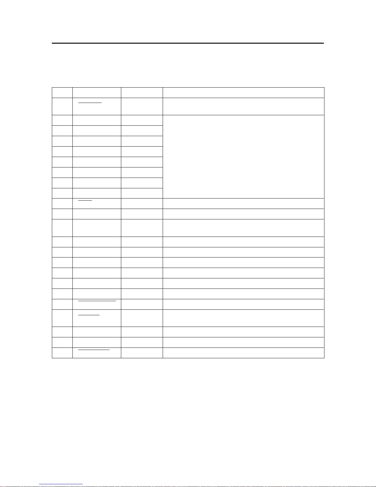
Pin No. Signal Name Direction Functional Description
Goes from High to Low (for at least 0.5 microseconds) when data
are valid.
Eight-bit character data. DATA8 is the most significant bit; DATA
1 is the least significant bit.
High is logic 1 and Low is logic 0.
Approx.9-Microsecond Low pulse acknowledges receipt of data.
Low when the printer is ready to accept data.
Goes High if the printer runs out of paper.
Can be held Low permanently by turning DIP switch 1-5 off.
High when the printer is on-line.
Unused
Signal Ground
Printer’s chassis ground, isolated from signal ground.
External supply of +5V DC.
Twisted pair return signal ground level.
Low input resets the printer to its power-up condition.
Goes Low to signal that the printer cannot print due to an error
condition.
External ground
Unused
Always High.
1 STROBE IN
2 DATA 1 IN
3 DATA 2 IN
4 DATA 3 IN
5 DATA 4 IN
6 DATA 5 IN
7 DATA 6 IN
8 DATA 7 IN
9 DATA 8 IN
10 ACK OUT
11 BUSY OUT
12 PAPER OUT OUT
13 SELECTED OUT
14, 15 (NC)
16 SIGNAL GND
17 CHASSIS GND
18 +5VDC OUT
19 ~ 30 GND
31 INPUT-PRIME IN
32 ERROR OUT
33 EXT GND
34, 35 (NC)
36 SELECT-IN IN
Page 15
– 12 –
GENERAL SPECIFICATIONS
3-2. Commodore Interface
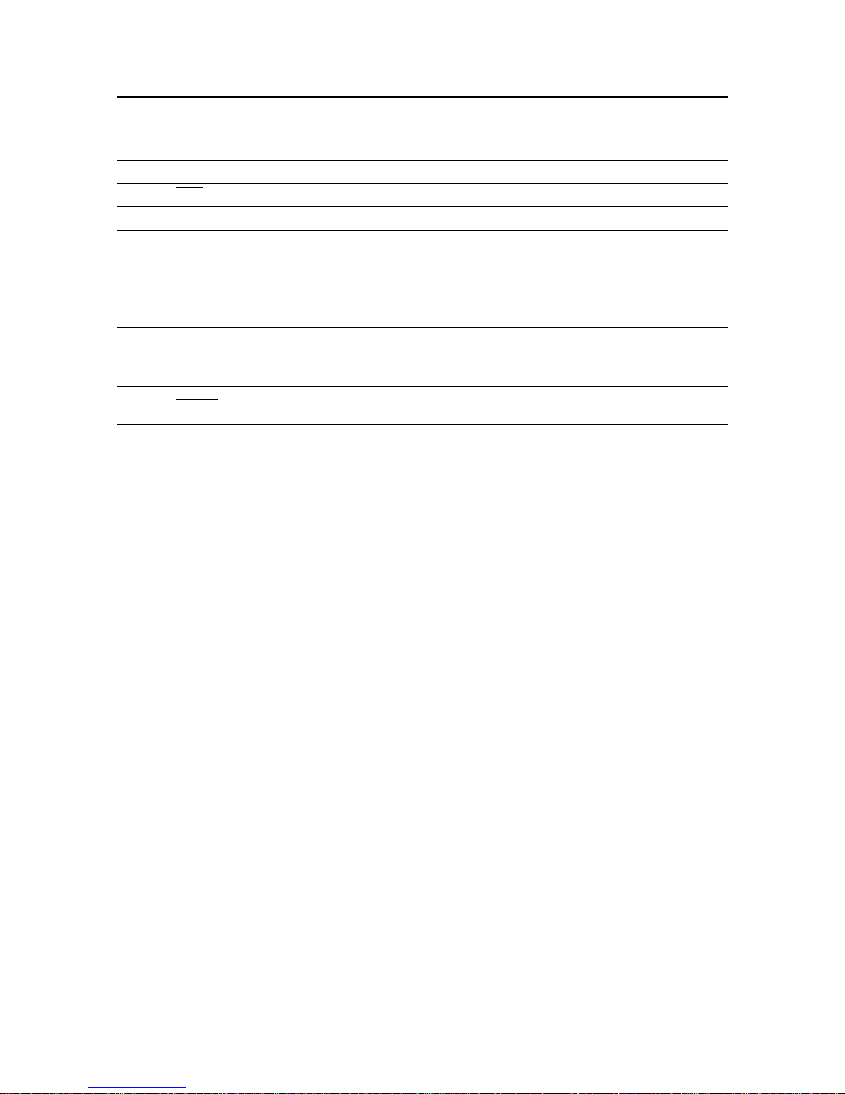
Pin No. Signal Name Direction Functional Description
1 SRQ OUT
2 GND
3 ATN IN
4 CLK IN
5 DATA IN/OUT
6 RESET IN
Not used.
Signal ground.
Serial Attention In
High.....................Signifies the data transfer mode.
Low .....................Signifies the command transfer mode.
Serial Clock In
The printer begins reading data on the rising edge of this signal.
Serial Data In/Out
IN: Conveys commands and data from the computer to the printer
OUT: High indicates printer ready Low indicates printer busy.
When this signal level goes low, the printer is initialized
and the memory buffer is cleared.
Page 16

CHAPTER 2
THEORY OF OPERATION
1. Block Diagram ..................................................................................................... 15
2. Main Logic Board ................................................................................................ 16
2-1. Data Input Operation............................................................................................. 16
2-1-1. Parallel Interface ............................................................................................... 16
2-1-2. Commodore Interface.......................................................................................17
2-2. General Flow Chart ............................................................................................... 19
2-2-1. Editing ............................................................................................................... 20
2-2-2. Print Head Driving Circuit ................................................................................ 20
2-2-3. Carriage Motor Driving Circuit......................................................................... 20
2-2-4. Carriage Motor Speed Control......................................................................... 21
2-2-5. Paper Feed Motor Driving Circuit.................................................................... 22
2-3. Reset Circuit .......................................................................................................... 23
2-4. Reset by +5V Line Voltage Detection .................................................................. 24
2-5. Protection Circuit .................................................................................................. 24
3. Power Supply Unit .............................................................................................. 24
4. Mechanisms......................................................................................................... 25
4-1. Print Head Mechanism.......................................................................................... 25
4-2. Print Head Carrying Mechanism .......................................................................... 25
4-3. Ink Ribbon Feed Mechanism................................................................................ 26
4-4. Paper Feed Mechanism ........................................................................................ 27
4-5. Detectors ............................................................................................................... 28
1
2
3
4
5
6
7
8
A
Page 17

– 14 –
THEORY OF OPERATION
Page 18
– 15 –
THEORY OF OPERATION
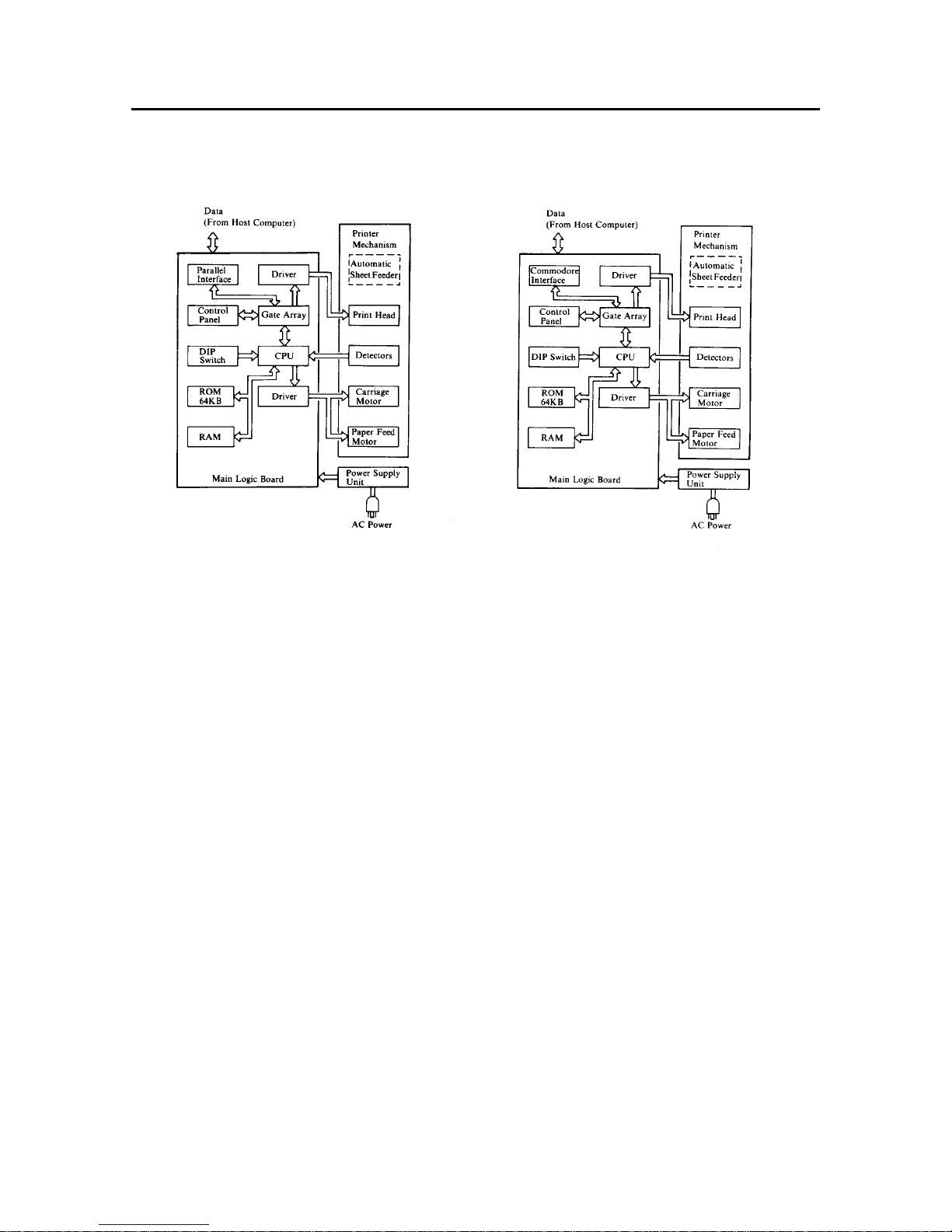
1. Block Diagram
The block diagram of this printer is shown in Fig. 2-1.
Parallel Type Commodore Type
Fig. 2-1 Block Diagram
(1) Main Logic Board
This board receives data from the host computer and stores it in the RAM in the order of arrival. The CPU on this
board reads the data from the RAM and edits it according to the program stored in the ROM.
When the editing is completed, various drive signals from the CPU are sent to the printer mechanism to perform
printing.
<Explanation>
1 CPU M50734SP
• Controls this printer.
2 ROM µPD27C512 64K-byte
• Contains the program which executes control of the printer.
3 RAM 8K-byte (Monochrome type), 32K-byte (Colour type)
• Used as stack area, work area and data buffer of the CPU.
4 Parallel interface (Parallel type only)
5 Commodore interface (Commodore type only)
6 Gate array (custom IC)
• Inputs or outputs several signals.
7 Driver
• The data edited by the CPU and gate array are sent to the printer mechanism after conversion to the signal
for the print head drive, carriage motor drive, and paper feed motor drive respectively.
8 Control Panel Circuit
This panel circuit is for manual operation of the printer.
(2) Printer Mechanism
The printer mechanism consists of a print head, carriage motor, paper feed motor, and detectors.
(3) Power Supply Unit
AC power is converted to DC24V and DC5V.
Page 19
– 16 –
THEORY OF OPERATION
2. Main Logic Board
2-1. Data Input Operation
2-1-1. Parallel Interface (Parallel type only)
Communications between the host computer and this printer are facilitated via parallel connectors. This section explains
the handshake of this interface.
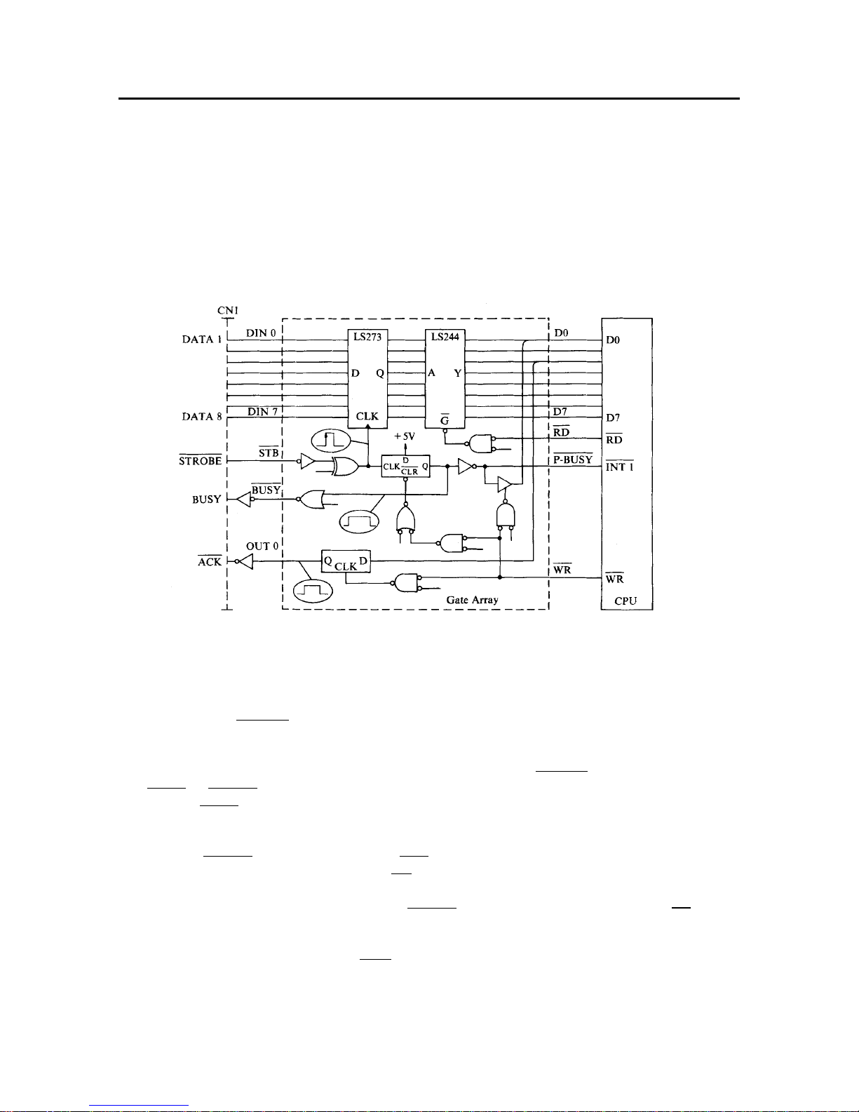
The data input circuit of this interface is shown in Fig. 2-2.
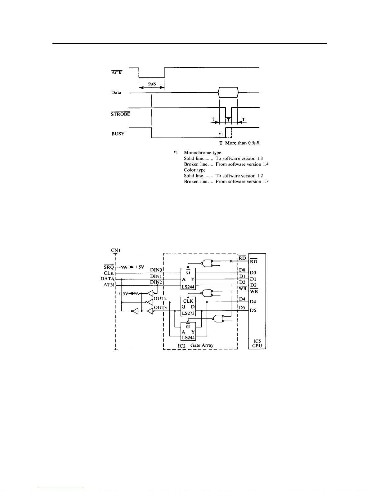
Fig. 2-2 Data Input Circuit with Parallel Interface
The following is an explanation of this handshake.
(1) When the BUSY signal is LOW (Ready), the host computer outputs 8- bit data 1 through 8 to the connector CN1.
Pin 1 carries the STROBE pulse signal from the host computer to the printer.
This signal is normally held HIGH by the host computer. When the host computer has data ready for the printer,
it sets this signal to LOW for at least 0.5 µS.
(2) The gate array of the main logic board reads data 1 through 8 at the time of STROBE signal fall, and then turns the
BUSY and P-BUSY signals to low.
(3) When the BUSY signal of the gate array is set to LOW, the BUSY signal of connector CN1 will be turned to HIGH,
notifying the host computer that data cannot be accepted.
(4) Ver. 1 Board
When the P-BUSY signal goes LOW, the CPU INT1 signal also goes LOW, causing a CPU interrupt.
If such an interrupt occurs in the CPU, set the RD signal to LOW, and read the gate array into the CPU.
Ver. 1.5 Board and Ver. 2 Board
The CPU is informed via the D0 data line that the P-BUSY terminal is LOW. Because of this, set the RD signal to
LOW and read the gate array into the CPU.
(5) Upon completion of the data reading, the CPU notifies the host computer of the data receivable state by setting the
BUSY signal of connector CN1 and the ACK signal to LOW for a certain period of time.
This concludes the explanation of the parallel interface handshake. The following chart describes the timing chart
of the handshake.
Page 20
– 17 –
THEORY OF OPERATION
Fig. 2-3 Timing Chart of Parallel Interface
2-1-2. Commodore Interface (Commodore type only)
The commodore interface is a serial interface which can be connected to COMMODORE network host computers.
The data input circuit with a Commodore interface is shown in Fig. 2-4.
Fig. 2-4 Data Input Circuit with Commodore Interface
Two types of the handshake mode are used with this Commodore interface:
Non-EOI handshake and EOI handshake. The timing chart of the Non-EOI handshake mode is shown in Fig. 2-5, and that
of the EOI handshake mode in Fig.2-6.
Page 21

– 18 –
THEORY OF OPERATION
Fig. 2-5 Timing Chart of Non-EOI Handshake Mode
Fig. 2-6 Timing Chart of EOI Handshake Mode
(1) Non-EOI handshake
This is a regular data transmission handshake.
1. The host computer acknowledges that the DATA line is low (data reception is completed), raises the CLK, and
notifies the printer that the host computer is ready to send (data or commands).
2. The printer sends information to the host computer by raising the DATA line to show that the printer is ready
to receive more data.
3. The host computer sends information to the printer that data is available after the next raising of the CLK, by
lowering the CLK.
4. After storing data, the host computer indicates that the data is available by raising the CLK.
The printer reads the data at the rising edge of the CLK. Then the host computer lowers the CLK and opens
the DATA line, acknowledging that the printer is in READY mode (DATA line is high), and moves to the next
bit handshake.
5. Sending 8-bit data is the same as above. When transmission is completed, the printer sends information to the
host computer that the receiving of data is finished by lowering the DATA line.
(2) EOI handshake
This handshake is used to show that the next data bytes are the last data.
1. The host computer acknowledges that the DATA line is LOW (receiving data is finished), and sends
information to the printer that the host computer is ready to send data (including commands) by raising the
CLK.
2. The printer sends information to the host computer that the printer is ready to receive data by raising the DATA
line.
At the rising edge the 500 µs timer starts.
(Until now this has been operating the same as the Non-EOI handshake.) From the starting of the timer, the
host computer keeps the CLK high for more than 500 µs to indicate EOI.
3. If the CLK does not fall within 500 µs, the printer acknowledges the EOI, and lowers the DATA line to LOW.
4. The printer sends information to the host computer that it is ready to receive data by raising the DATA line
again.
To send 8-bit data, follow the preceding Non-EOI handshake procedure.
Page 22
– 19 –
THEORY OF OPERATION
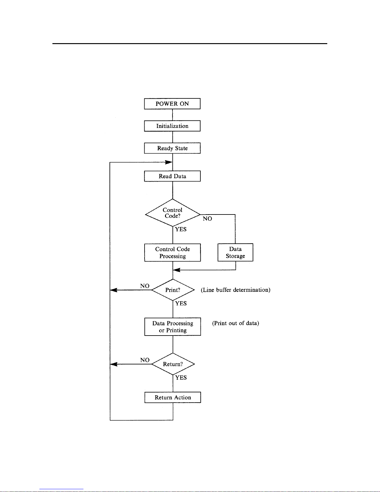
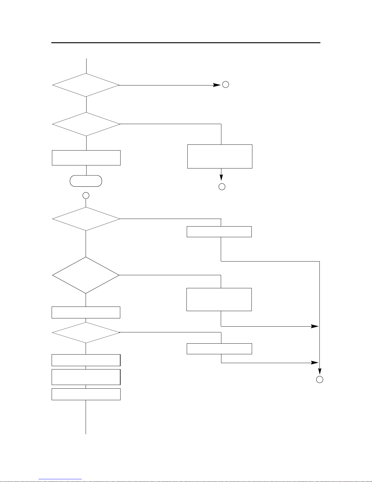
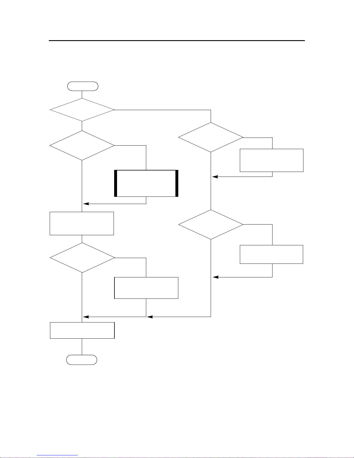
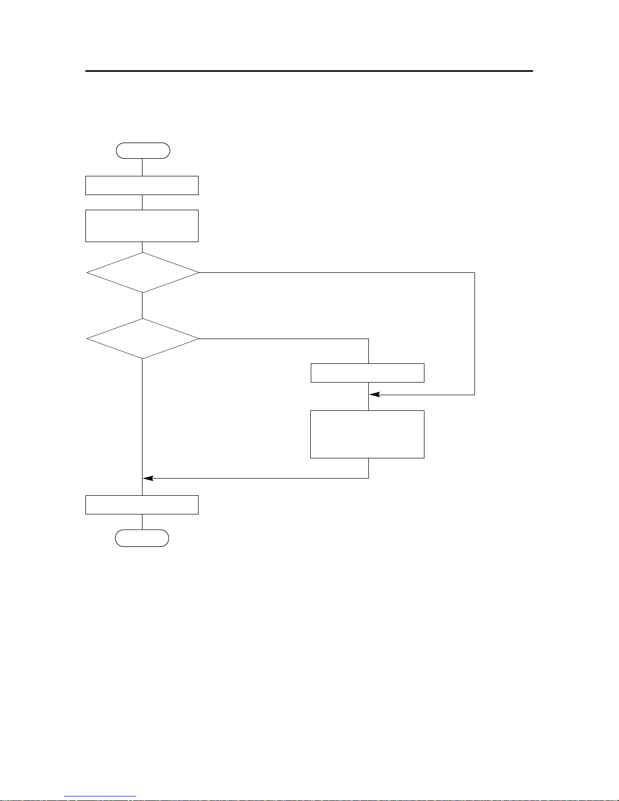
2-2. General Flow Chart
A general flow chart of editing and printing operations is presented in Fig. 2-7.
Fig. 2-7 General Flow Chart of Editing and Printing
Page 23
– 20 –
THEORY OF OPERATION
2-2-1. Editing
Data stored in the RAM is read out sequentially by the CPU and then edited according to a function code that has been
specified in advance.
This editing takes places until the CR or CR + LF code appears or the line buffer becomes full.
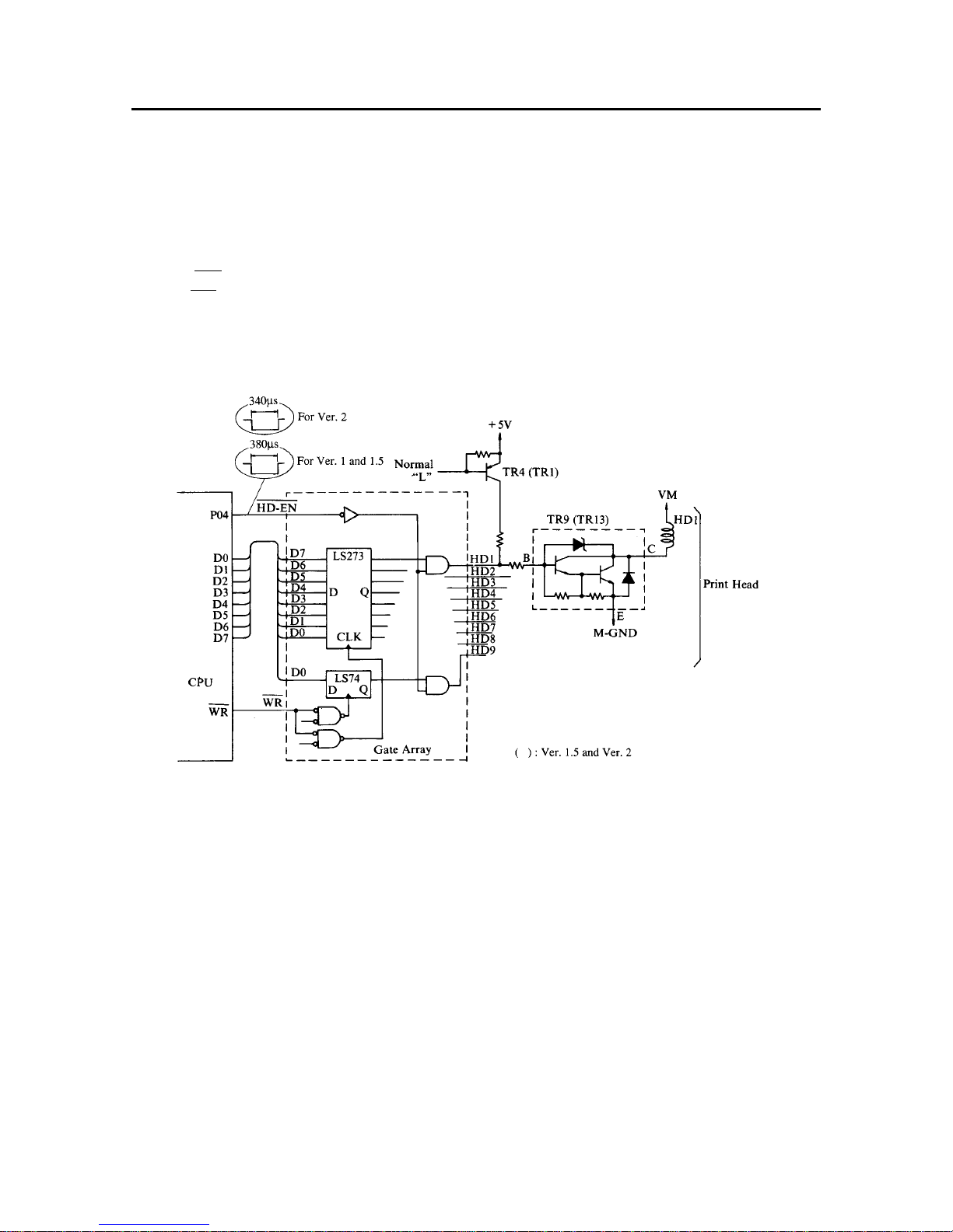
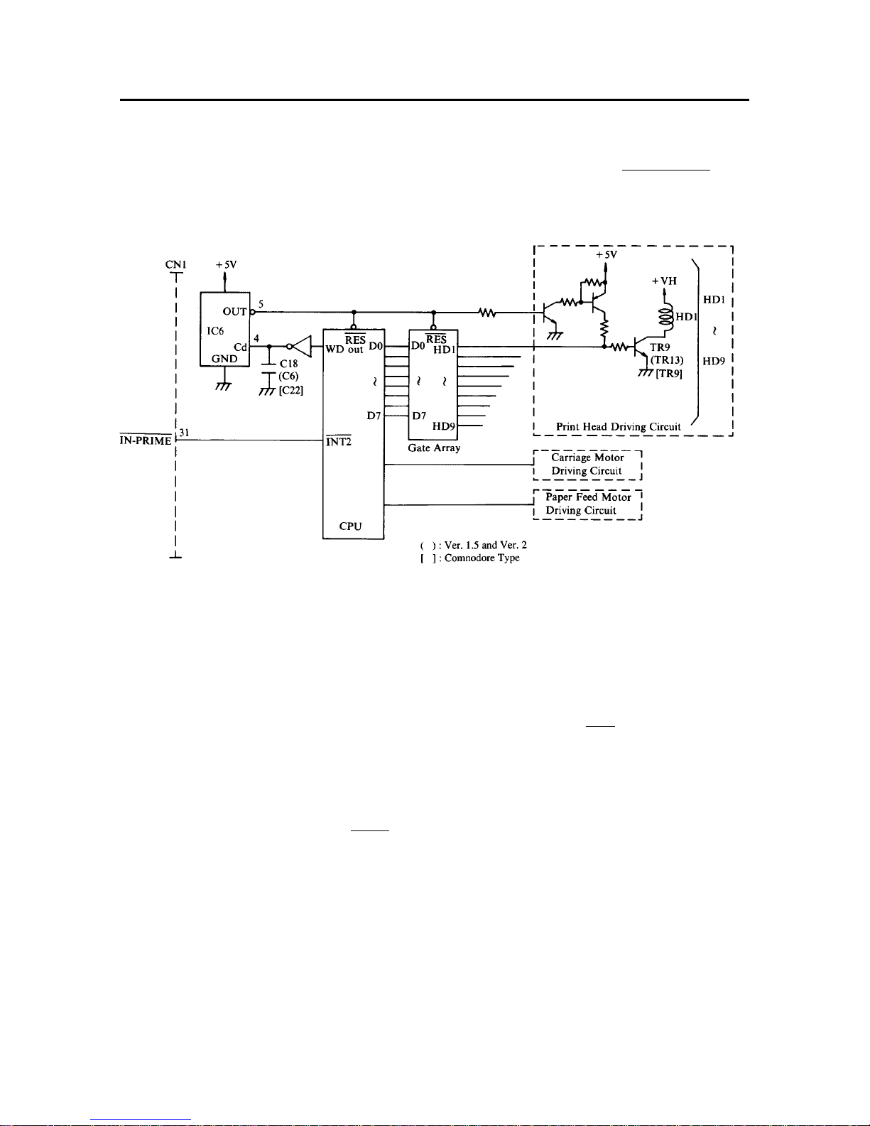
2-2-2. Print Head Driving Circuit
Edited print data is output to terminal Q of LS273 in the gate array through the CPU data bus, as regulated by the issue
timing of a WR signal. However, as for pin 9 (HD9) of the print head, the data is output to the same terminal upon issue
of the next WR signal. When all the data is received for printing, an energized time control signal is output from port PO4
of the CPU. This allows the print data to be output to HD-1 ~ 9 of the gate array. When the print data is HIGH, the transistor
TR9 will be turned ON for 380 µS (Ver 1 and 1.5), 340 µs (Ver 2), energizing the print head solenoid to drive the print
head.
Fig. 2-8 Print Head Driving Circuit
2-2-3. Carriage Motor Driving Circuit
This printer employs a stepping motor as the carriage motor. Unlike regular motors on the market, this stepping motor
will not operate just by connecting it to a power source. The motor operates only when a drive pulse is fed to it, but even
then, it turns only a certain angle.
This stepping motor is characterized by 4-phase stepping. Control of the motor is facilitated by phase 1-2 excitation. The
following is the description of the carriage motor drive circuit and the control signal generated by the phase 1-2 excitation
method.
Page 24
– 21 –
THEORY OF OPERATION
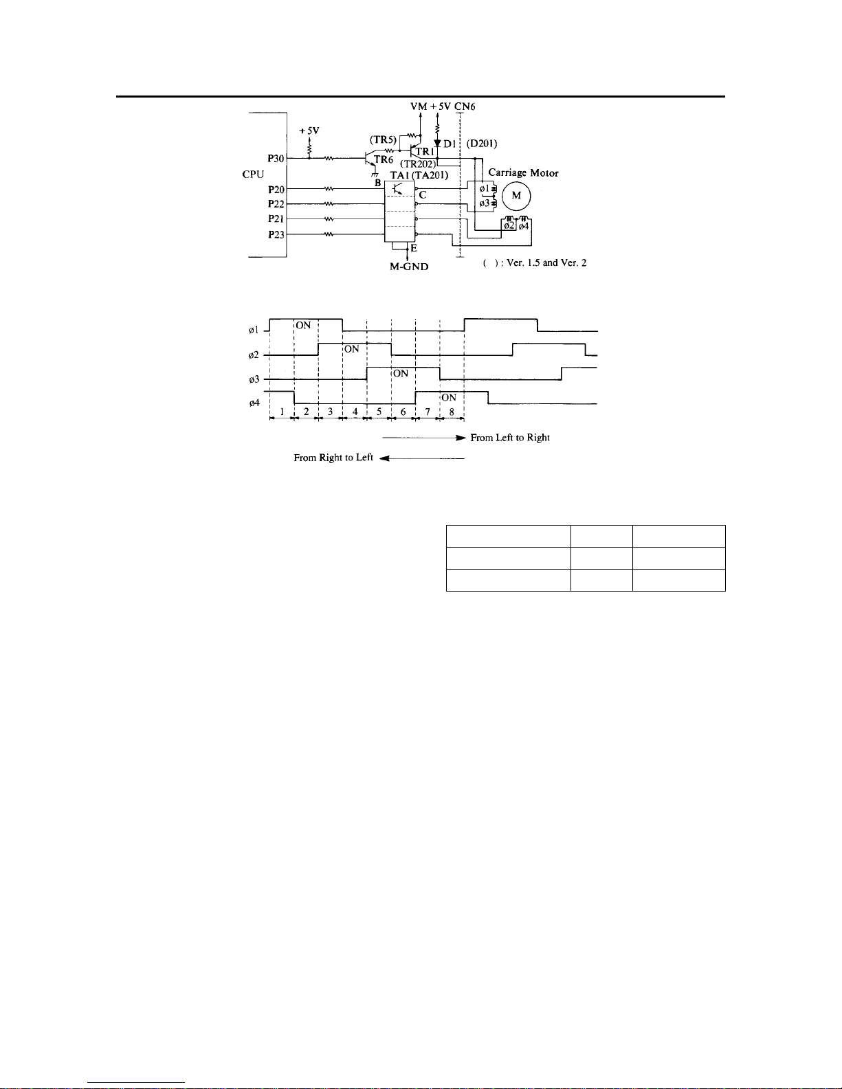
Fig. 2-9 Carriage Motor Driving Circuit
Fig. 2-10 Carriage Motor Driving Signals
The utilization of voltage applied to the carriage motor is
described below:
Voltage applied to the carriage motor is changed by setting port
P30 of the CPU to HIGH or LOW and by turning transistors
TR6 and TR1 ON or OFF.
When TR1 is ON, +24V is supplied to the carriage motor and
when TR1 is OFF, +5V is supplied to the motor via diode D1.
2-2-4. Carriage Motor Speed Control
Since the carriage motor is a stepping motor, the carriage can be stopped at a desired position by controlling acceleration
and deceleration. The carriage can also move backward.
The rotational speed of the carriage motor is set by the number of pulses per time unit. The character pitch (horizontal
character size) in each print mode is determined by changing this rotational speed (or carriage transfer speed).
(1) At start-up of the motor:
The number of pulses input to the motor increase in steps (36 altogether), reaching a certain frequency.
(2) To stop the motor:
The number of pulses input to the motor decreases in steps (36), in order to gradually bring the motor to a halt.
(3) When printing is carried out:
Pulses of a uniform pulse width are supplied for printing.
Mode Voltage Application
Operation: +24V Motor Drive
Standby: +5V Holding Bias
Page 25
– 22 –
THEORY OF OPERATION
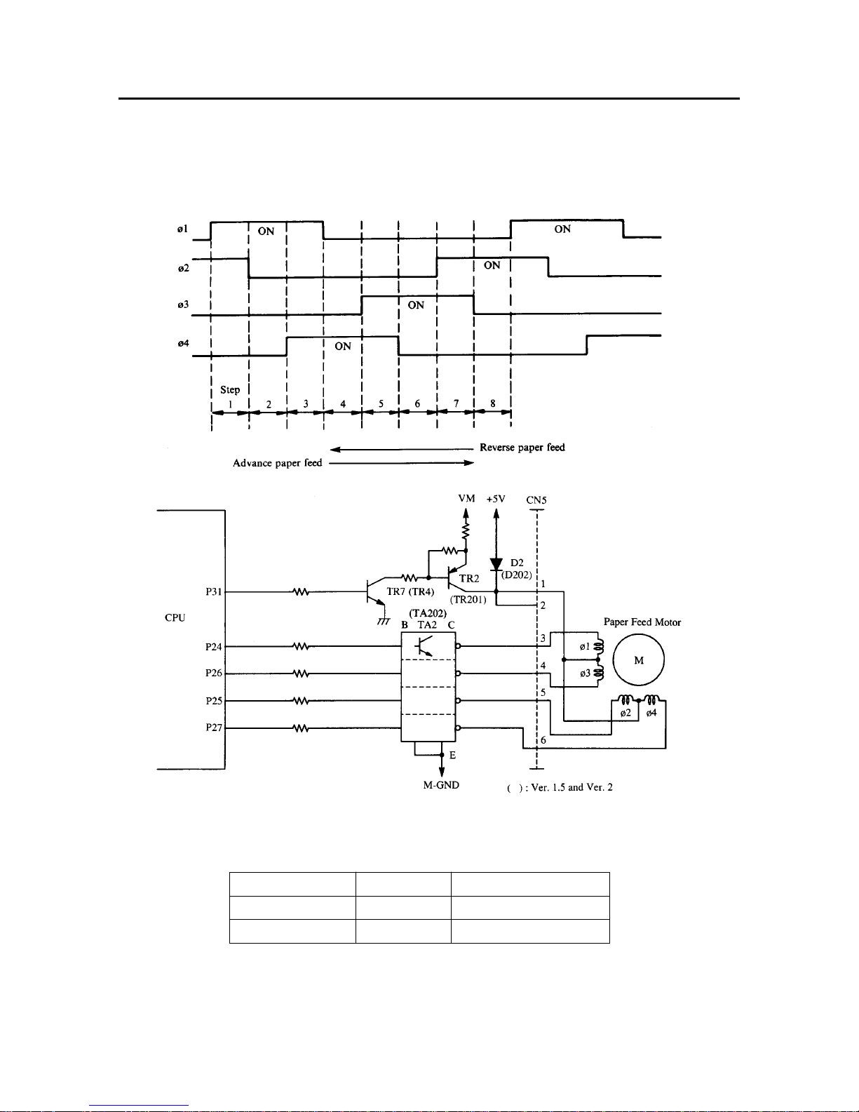
2-2-5. Paper Feed Motor Driving Circuit
Again, a stepping motor is employed as the paper feed motor, which turns a certain angle only when a drive pulse is
received. This 4-phase stepping motor is controlled by the phase 1-2 excitation method. The following is the description
of the paper feed motor drive circuit and the control signal generated by the phase 1-2 excitation method.
Fig. 2-11 Paper Feed Motor Driving Circuit
Fig. 2-12 Paper Feed Motor Driving Signals
The utilization of voltage applied to the paper feed motor is described as follows.
Mode Voltage Application
Operation +24V Motor Drive
Standby: +5V Holding Bias
Voltage to the paper feed motor is changed by setting CPU port P31 to LOW or HIGH and by turning transistors TR7 and
TR2 ON or OFF.
When TR2 is turned on, +24V is applied to the paper feed motor.
When TR2 is turned off, +5V is supplied to the motor via diode D2.
Page 26
– 23 –
THEORY OF OPERATION
2-3. Reset Circuit
The RESET signal initializes the circuit elements and prevents operation errors when the power is turned on.
The RESET signal is output for approx. 34ms. when the power is turned on, or while the RESET ( INPUT-PRIME ) signal
is being output from the host computer.
Fig. 2-13 Reset Circuit and Protection Circuit.
• Power On Reset
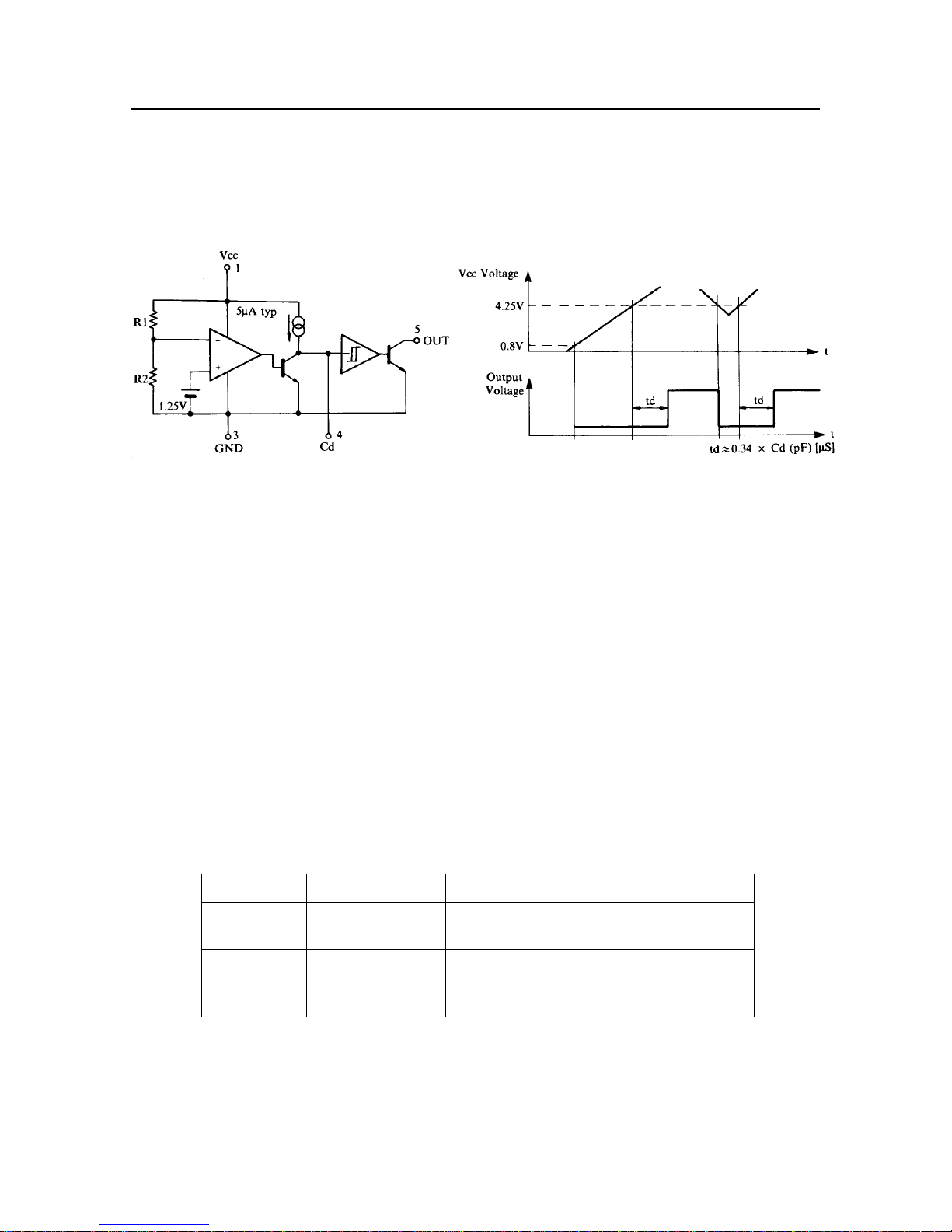
1 When the power is turned on, the RESET signal output from Pin 5 of IC6 (M51953BL) for approx. 34 msec. This time
length is determined by external capacitor C18 (0.1µF), and it can be calculated by the following formula.
T = 0.34 × C18 (pF) µsec.
2 This LOW signal triggers RESET command to the CPU and the RESET terminal ( RES ) of the gate array.
3 Resetting the CPU and the gate array will ignore all the drive signals for the carriage motor, the paper feed motor and
the print head, preventing operation errors at power ON.
• Reset by Input Prime Signal from Host Computer
1 The input prime signal from the host computer is output to pin 31 of the connector CN1.
2 This output signal will set the terminal INIT 2 of the CPU to LOW, executing interruption. Then, the CPU will be
initialized.
Page 27
– 24 –
THEORY OF OPERATION
2-4. Reset by +5V Line Voltage Detection
A voltage-detecting IC (IC6 in Fig.2-13) detects momentary drops in voltage or unstable voltage supply (due to power
failures, etc.) on the +5V line. If the voltage on the +5V line falls below 4.25V, the RESET signal appears at the output
terminal of the voltage-detecting IC.
Fig. 2-14 Equivalent Circuit of Fig. 2-15 Operational Timing Chart
Voltage-Detecting IC
2-5. Protection Circuit
This printer is provided with a protection circuit which shuts off the print head and motor driving circuits in the event of
a CPU malfunction. (Refer to Fig.2-13)
The CPU normally outputs a LOW level signal from the terminal (WD OUT).
However, if the CPU malfunctions, it can not output this signal.
When the LOW level signal is not output from the CPU, the input terminal (Cd) of the voltage-detecting IC goes to LOW
and the RESET signal is output from the output terminal (OUT) of the voltage-detecting IC. By this signal, the CPU and
the gate array are reset and the print head, the carriage motor and paper feed motor driving signals are ignored, protecting
the printer from the CPU runaway.
3. Power Supply Unit
The power supply circuit converts the incoming AC power to DC voltages, +5V and +24V.
Voltage Tolerance Application
+24V DC24V±5% To drive print head, carriage motor, paper feed
motor.
+5V DC5V±2.5% To supply power to CPU, ROM, RAM, TTL
and ICs and to retain carriage motor and paper
feed motor.
Page 28
– 25 –
THEORY OF OPERATION
4. Mechanism
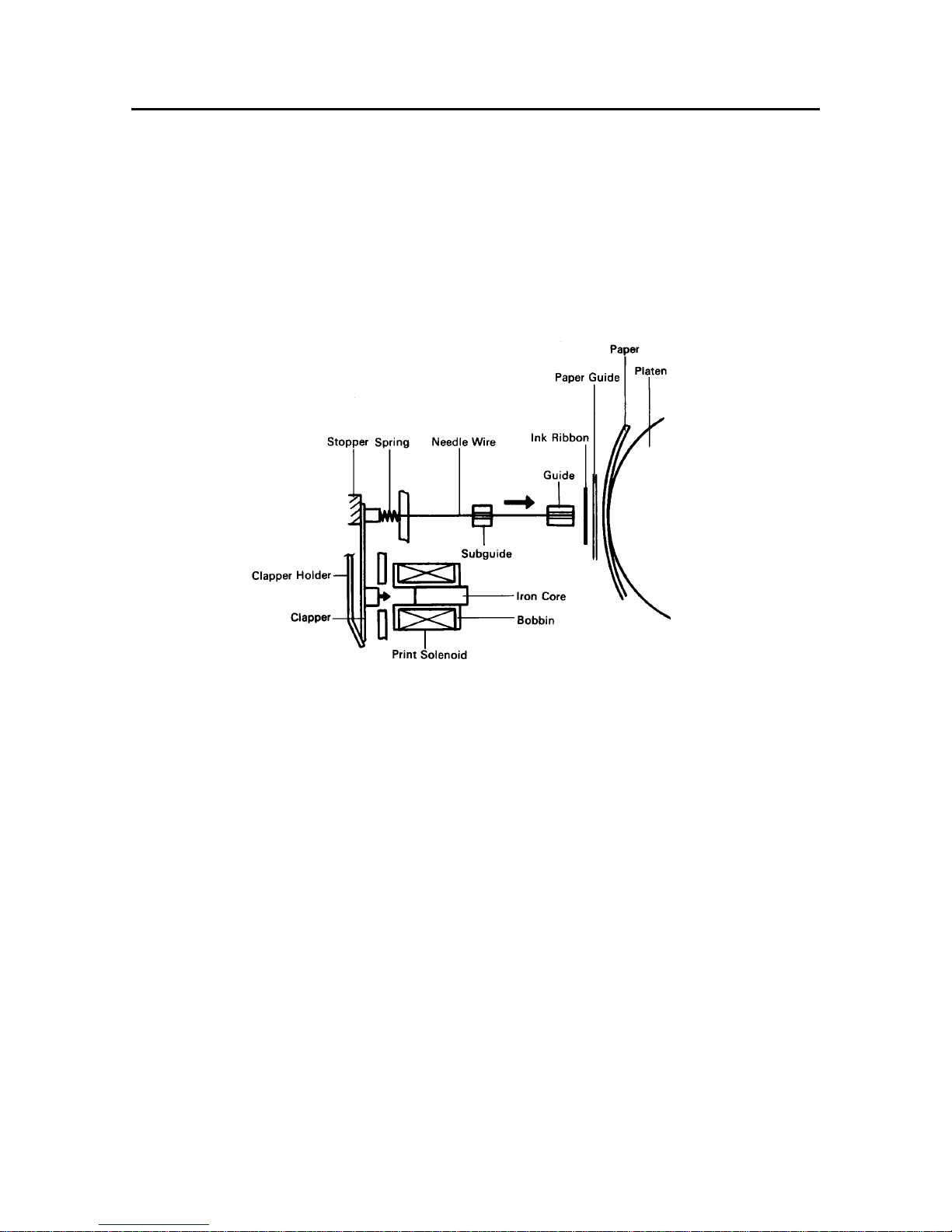
4-1. Print Head Mechanism
The print head consists of 9 needle wires and 9 print solenoids.
The following explains how each needle wire operates during printing.
(1) When the print solenoid is energized, the clapper is attracted by the iron core and the needle wire is driven toward
the platen.
(2) This needle wire hits the platen via the ink ribbon and paper. A single dot is printed on the paper.
(3) When the print solenoid is de-energized, the needle wire is returned to its original position by rebound energy and
spring and clapper holder (leaf spring) force.
Fig. 2-16 Outline of Print Head Mechanism
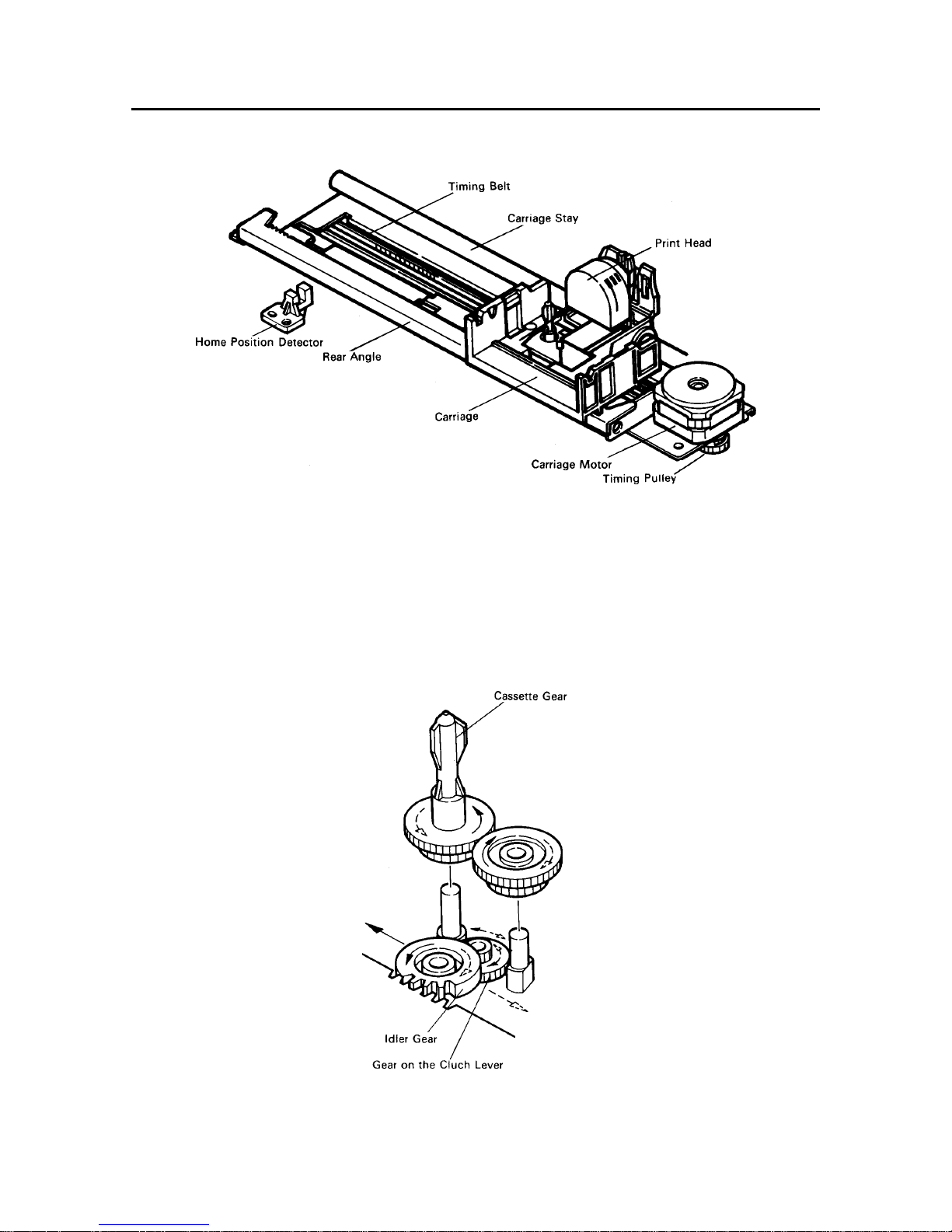
4-2. Print Head Carrying Mechanism
The print head carrying mechanism consists mainly of a carriage, timing belt, carriage motor, and home position detector.
(1) Carriage
The carriage is supported horizontally by means of the carriage stay and rear angle, and it moves from side to side
with the print head mounted above it. A timing belt is clamped to the base of the carriage and a shield plate is mounted
at the base for home position detection.
(2) Timing Belt
The timing belt is suspended between the timing pulley of the carriage motor and the timing pulley of the tension
lever, and it maintains a constant tension.
The timing belt is also clamped to the base of the carriage so that it can move the carriage accurately with driving
force from the carriage motor.
(3) Carriage Motor
The carriage motor is a PM (Permanent Magnet) type, four-phase and 48-pole pulse motor, which is driven by pulse
signals from the control circuit. The rotational rate depends on the number of pulses per unit time. By varying this
rotational rate (that is, the carriage carrying rate), the size of the horizontal letters can be changed in each print mode.
Page 29
– 26 –
THEORY OF OPERATION
Fig. 2-17 Print Head Carrying Mechanism
4-3. Ink Ribbon Feed Mechanism
The ink ribbon feed mechanism is linked to the print head carrying mechanism described previously so that the ink ribbon
is wound up automatically while the carriage moves left or right.
The ribbon feed mechanism is driven by torque from the carriage motor, and carriage movement allows the idler gear to
rotate.
This rotation is conveyed sequentially to the gears that work to wind the ribbon. The carriage is equipped with a clutch
lever so that the direction of cassette gear rotation remains constant regardless of the direction of the idler gear rotation.
Fig. 2-18 Ribbon Feed Mechanism
Page 30
– 27 –
THEORY OF OPERATION
Not Linked
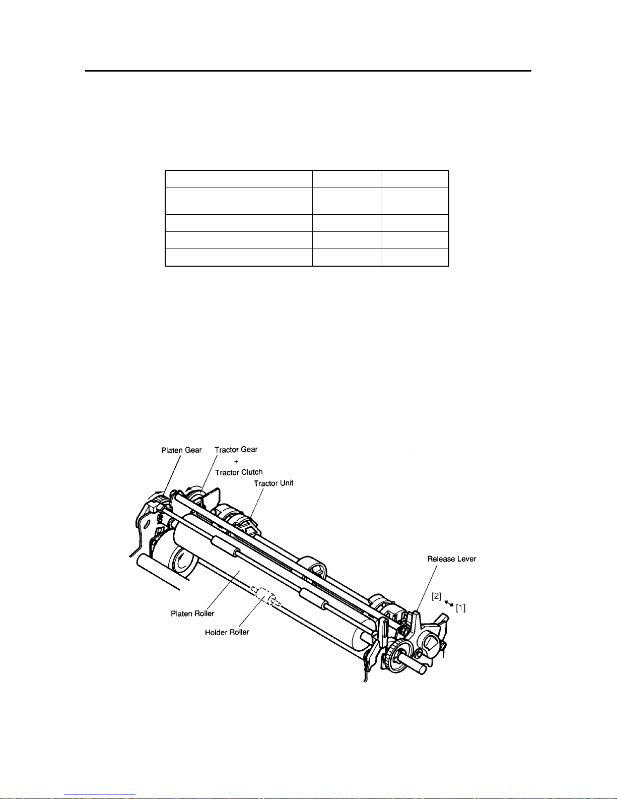
4-4. Paper Feed Mechanism
The paper feed motor is a PM type, four-phase and 48-pole pulse motor.
Minimum paper feed is set at 1/216 inch.
There are two ways of feeding paper available with this printer: Friction method and Tractor method. You can select one
of the two methods, using the release lever.
Position of release lever [1] [2]
Linkage between tractor
gear and tractor clutch
Platen roller and holder roller Pressured Not
Release lever position detector Closed Open
Paper feeding method Friction Tractor
(1) Friction Method
Friction method is selected when the release lever is position [1].
With this method, paper is pressed between the platen roller and the holder roller therefore, paper is fed as the rollers
turn.
As the paper feed motor is driven, the motor gear, through the idler gear, turns the platen gear in the paper feeding
direction. However, since the tractor gear and the tractor clutch are not linked at this time, the tractor unit will not
be driven.
(2) Tractor Method
Tractor method is selected when the release lever is position [2].
As described below, paper feeding is facilitated by rotation of the sprocket pin of the tractor unit. When the tractor
method is selected, the tractor gear is linked to the tractor clutch, enabling the drive force generated by the paper
feed motor to be transferred to the tractor unit via the idler gear and the platen gear.
Fig. 2-19 Paper Feed Mechanism
Page 31

– 28 –
THEORY OF OPERATION
4-5. Detectors
(1) Home Position Detector
A photo-interrupter is used in the home position detector, which is set at the left side of the frame unit.
ON/OFF signals are generated according to the position of the shield plate mounted at the base of the carriage, and
the printing position is determined by these signals.
(2) Paper Out Detector
A paper out detector is located at the paper insertion slit. When paper is present, the reed switch of the sensor is
OPEN. As soon as paper runs out, the switch is set to CLOSE, outputting a paper empty signal.
Fig. 2-20 Home Position Detector Fig. 2-21 Paper Out Detector
(3) Bail Lever Position Detector
Upon detecting the position of the bail lever, the auto loading operation will be activated.
The leaf switch is open when the bail roller is in contact with the platen roller, and it is closed when the bail roller
is separated from the platen roller.
(4) Release Lever Position Sensor
The leaf switch is closed when the release lever is in the Friction position, and is open in the Tractor position.
Fig. 2-22 Bail Lever Position Detector Fig. 2-23 Release Lever Position Detector
Page 32

CHAPTER 3
ADJUSTMENTS
This printer has undergone various adjustments so that it will achieve standard performance. In this chapter,
a brief explanation is given of the methods of adjustments.
Please check this explanation when making maintenance inspections or when replacing parts to correct
malfunctions.
1. Gap Adjustment Between Print Head and Platen ............................................ 31
1-1. Measuring Gap Between Print Head and Platen.................................................31
1-2. Adjusting Gap Between Print Head and Platen.................................................. 31
2. Adjustment of Timing Belt Tension................................................................... 32
3. Adjustment of Home Position (Colour Type only) ........................................... 33
3-1. Measuring Gap Between Home Position Detector and Frame..........................33
3-2. Adjusting Gap Between Home Position Detector and Frame ...........................33
4. Adjustment of Colour Ribbon Holder (Colour Type only)............................... 34
1
2
3
4
5
6
7
8
A
Page 33

ADJUSTMENTS
– 30 –
Page 34

ADJUSTMENTS
– 31 –
1. Gap Adjustment Between Print Head and Platen
1-1. Measuring Gap Between Print Head and Platen
(1) Remove the upper case unit according to procedures
described in chapter 4.
(2) Set the adjustment lever [1] at step two.
(3) Remove the ribbon guide [2].
(4) Insert a thickness gauge [3] between the print head[4]
and the platen [5], and measure the gap.
(5) This measurement must be carried out at the center
[C].
(6) The standard gap value is 0.30 to 0.40 mm.
(7) If the gap does not lie within this range, adjust it by
following the procedure in item 1-2.
Fig. 3-2 Position of Adjustment Lever Fig. 3-3 Gap Measurement
1-2. Adjusting Gap Between Print Head and Platen
If the gap does not lie within the standard range, adjust it by
carrying out the following procedures.
(1) Remove the printer mechanism according to the
procedures described in chapter 4.
(2) Loosen the nut [6].
(3) Insert the shaft in the ø2.5 hole [7].
Adjust the gap by rotating the carriage stay [8] with
the shaft.
When the shaft is lowered to the platen side, the gap
is reduced, and when lowered to the opposite side,
the gap is expanded.
(4) After adjusting, set the adjustment lever [1] to the
position shown in Fig. 3-2 and tighten the nut [6].
(Note) When tightening the nut [6], make sure that the
carriage stay [8] does not move.
Fig. 3-1 Gap Adjustment
Fig. 3-4 Gap Adjustment
Page 35
ADJUSTMENTS
– 32 –
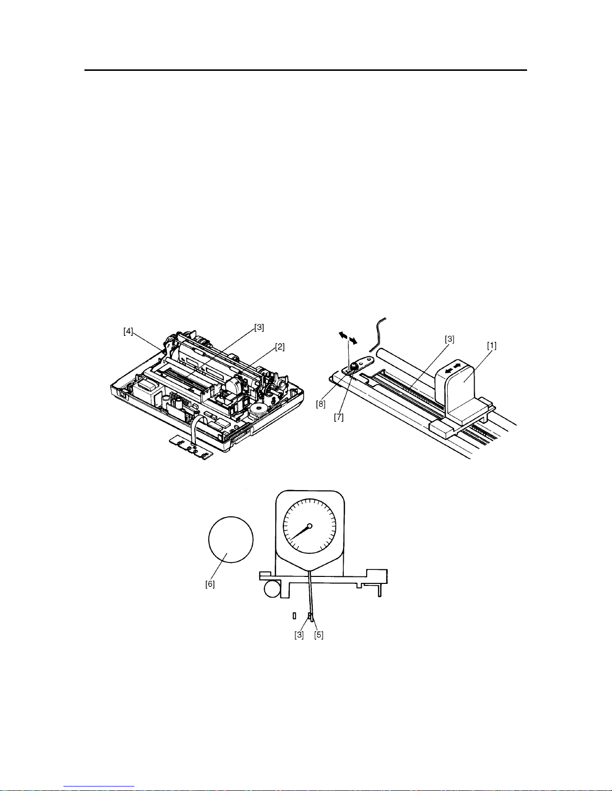
2. Adjustment of Timing Belt Tension
The timing belt tension should be set to 16±2 g for MONO type (20±3 g for CL type).
(The belt tension must be measured with the designated tension gauge [1].)
After the belt has been used for a long time, however, it may be difficult to maintain prescribed tension because of belt
deterioration or wear. In these cases, make adjustments by following the procedures listed below.
(1) Remove the upper case unit according to the procedures described in chapter 4.
(2) Move the carriage unit [2] right and left two or three times in order to familiarize yourself with the timing belt [3].
(3) Set the adjustment lever [4] to step 2 as shown in Fig. 3-2.
(4) Move the carriage unit [2] to the right end.
(5) Set the arm [5] of the tension gauge [1] 152 mm from the frame L.
(6) Move the tension gauge [1] in the direction of the platen [6] until it stops. Then place the arm [5] of the tension gauge
on the timing belt [3].
(7) Loosen the screw [7].
(8) Insert a flat-blade screwdriver into the square hole of the tension arm [8] and adjust the belt tension by moving the
tension arm [8] left or right.
(9) When the belt has been adjusted to the prescribed tension, tighten the setting screw [7].
(10) If the belt cannot be adjusted to the prescribed tension, replace it with a new timing belt [3].
Fig. 3-5 Adjustment of Timing Belt Tension
Fig. 3-6 Tension Measurement
Page 36

ADJUSTMENTS
– 33 –
3. Adjustment of Home Position (Colour Type only)
3-1. Measuring Gap Between Home Position Detector and Frame
(1) Remove the printer cover [1] .
(2) Measure gap between home position detector [2] and frame [3] .
(3) The standard gap value is 2.4 to 3.0 mm.
(4) If the gap does not lie within this range, adjust it by following the procedure in item 3-2.
Fig. 3-7 Position of Home Position Fig. 3-8. Gap Adjustment
3-2. Adjusting Gap Between Home Position Detector and Frame
If the gap does not lie within the standard range, adjust it by carrying out the following procedures.
(1) Remove the upper case according to procedures described in chapter 4.
(2) Loosen the four screws [4] .
(3) Move the printer mechanism.
(4) Insert the thickness gauge (2.7 mm) between the home position detector [2] , and frame [3] .
(5) Tighten the four screws [4] .
Fig. 3-9 Position of Four Screws
Page 37

ADJUSTMENTS
– 34 –
4. Adjustment of Colour Ribbon Holder (Colour Type only)
This adjustment requires use of the carriage unit to fix the position of the color ribbon holder on older parts (see drawings
no. 1-24 and 1-25, chapter 7, part 3-3-2). However, newer parts (nos. 1-30 and 1-31) do not require use of the carriage
unit.
Adjustment of the colour ribbon holder properly positions the ink ribbon cartridge vertical to the print head when the
cartridge is installed on the colour ribbon holder. (Refer to Fig. 3-10.) Failure to perform this adjustment may cause some
kinds of defective printing such as printing in “YELLOW” ink when printing should be done in “RED” ink.
The following is the adjustment procedure.
(1) Execute Self Printing [1].
(2) Judging from the print sample printed just now, decide if the ink ribbon cartridge should be moved upward or
downward of the print head.
(3) Remove the printer cover and ink ribbon cartridge [1] .
(4) Turn the adjusting screws A [2] and B [3] (brass parts)
counter-clockwise to move the ribbon cartridge upward.
clockwise to move the ribbon cartridge downward.
(5) Install the ink ribbon cartridge and printer cover.
(6) Execute self printing.
(7) Check the printing condition on the print sample.
If additional adjustment is required, repeat the procedure from (2) to (7).
*1 Self printing
1. Insert the paper.
2. With power off, press the On Line switch on the control panel and hold it down.
3. Still holding the On Line switch down, turn the printer’s power on.
Fig. 3-10 Needle Wire Position of Print Head
Fig. 3-11 Position of Adjusting Screws Fig. 3-12 Adjusting of Colour Ribbon Holder
Page 38

CHAPTER 4
PARTS REPLACEMENT
This chapter explains disassembly and reassembly of the printer.
Note the following precautions during disassembly and reassembly.
1. Disconnect the printer from the wall outlet before servicing it.
2. Assembly is the reverse of disassembly unless otherwise specified.
3. After reassembly, coat the screw heads with locking sealant.
4. Lubrication information is not provided in this chapter. Refer to item 2 in chapter 5.
1. Upper Case Unit ..................................................................................................37
2. Printer Mechanism .............................................................................................. 37
3. Main Logic Board ................................................................................................ 38
4. Power Supply Unit .............................................................................................. 39
5. Fuses .................................................................................................................... 40
6. Print Head ............................................................................................................41
7. Carriage Motor Unit............................................................................................. 42
8. Platen Unit ........................................................................................................... 43
9. Tractor Unit.......................................................................................................... 43
10. Detector Unit........................................................................................................ 44
1
2
3
4
5
6
7
8
A
Page 39

PARTS REPLACEMENT
– 36 –
Page 40

PARTS REPLACEMENT
– 37 –
1. Upper Case Unit
(1) Turn off the power switch [1] .
(2) Remove
• Printer cover
• Rear cover
• Platen knob [2]
• Four screws [3]
(3) Move the Carriage Unit [4] over to the right so that
it aligns with the cut-out of the upper case unit [5] .
(4) Remove
• Upper case unit [5]
Clasp the back side of the upper case unit, and
gently push it further forward.
• Control panel board [6]
2. Printer Mechanism
(1) Remove
• Upper case unit according to the procedure de-
scribed in item 1.
• Stop ring [1]
• Release lever [2]
• Gear lever [3]
• Four tapping screws [4]
• Screw [5]
• Connector cover [6]
Lift up the tab of the connector cover, and slide it
to the right for removal.
• Printer head cable [7]
• Three connectors [8]
• Printer mechanism [9]
Caution in assembly:
Align the the ∆ mark on the Release lever [2] with
the ∆ mark on the Release gear [3] to install the
Release lever [2] .
Page 41

PARTS REPLACEMENT
– 38 –
3. Main Logic Board
(1) Remove
• Printer mechanism according to the procedure
described in item 2.
• Two connectors [1]
• Two tapping screws [2]
• Two screws [3]
• Main logic board [4]
For Ver. 1
For Ver. 1.5 For Ver. 2
Page 42
PARTS REPLACEMENT
– 39 –
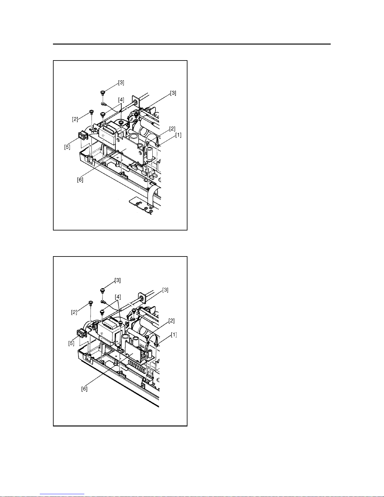
4. Power Supply Unit
(1) Remove
• Upper case unit according to the procedure de-
scribed in item 1.
• Connector [1]
• Two tapping screws [2]
• Two tapping screws [3]
• Two screws [4]
• Power switch [5]
• Power supply unit [6]
For Ver. 1 and 1.5
For Ver. 2
Page 43

PARTS REPLACEMENT
– 40 –
5. Fuses
For Ver. 1 and Ver. 1.5
(1) Remove
• Upper case unit according to the procedure de-
scribed in item 1.
(2) Inspect
• Fuse F1 [1]
• Fuse F2 [2]
• Fuse F3 [3] (For 120V only)
Defective→ Replace fuse as follows:
AC Voltage F1 (F3)
120V 5TT1A 5MT3.0
220V/240V 630mA –
The Destination Countries F2
EC, WG, NBR, SC, SU EAK2.0
US, TW, HK, UK, AS, MAS, UE 5MT2.0
New fuse blown → Inspect circuit
For Ver. 2
(1) Remove
• Upper case unit according to the procedure de-
scribed in item 1.
(2) Inspect
• Fuse F1 [1]
• Fuse F2 [2]
Defective → Replace fuse as follows:
AC Voltage F1
120V 5TT1A
220V/240V 630mA
The Destination Countries F2
EC, WG, NBR, SC, SU EAK3.15A
US, TW, HK, UK, AS, MAS, UE 5TT3A
New fuse blown → Inspect circuit
For Ver. 1 and 1.5
For Ver. 2
Page 44

PARTS REPLACEMENT
– 41 –
6. Printer Head
(1) Remove
• Printer cover
• Ink ribbon cartridge
• Connector cover [1]
• Gear Cover [2] (Colour type only)
• Two tapping screws [3]
• Head cable [4]
• Print head [5]
WARNING:
The print head becomes hot after printing so wait
for it to cool before removing it.
(2) Adjust
• Gap between print head and platen
Refer to item 1 of Chapter 3.
For Ver. 1 and 1.5
For Ver. 2
Page 45
PARTS REPLACEMENT
– 42 –
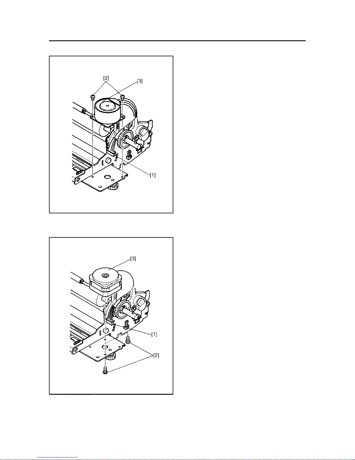
7. Carriage Motor Unit
(1) Remove
• Printer mechanism according to the procedure
described in item 2.
• Cord fastener binding the lead wires
• Connector [1]
• Two screws [2]
• Carriage motor unit [3]
For Ver. 1 and 1.5
For Ver. 2
Page 46
PARTS REPLACEMENT
– 43 –
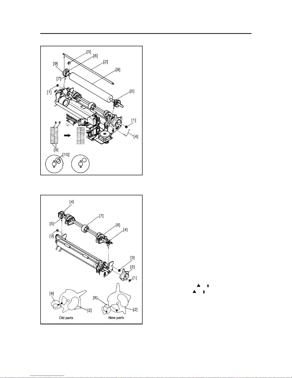
8. Platen Unit
(1) Remove
• Printer mechanism according to the procedure
described in item 2.
• Two nuts [1]
• Tractor stay [2]
• Stop ring [3]
• Ground contact spring [4]
• Platen holder R [5]
• Platen holder L [6]
Lift the tabs [7] of platen holders R and L to allow
removal of platen holders R and L from the frame.
• Platen unit [8]
Caution in assembly:
When assembling the platen gear assembly [9] on the
idler gear, align the teeth of gear A and gear B (be
sure to align the holes [10] in the two gears.)
(2) Adjust
• Gap between print head and platen
Refer to item 1 of Chapter 3.
9. Tractor Unit
(1) Remove
• Upper case unit according to the procedure de-
scribed in item 1.
• Stop ring [1]
• Release lever [2]
• Two nuts [3]
• Two tractor bushings [4]
Lift the tab [5] of the tractor bush to allow
removal of the tractor bush from the frame.
• Tractor unit [6]
Caution in assembly:
• For reassembly, hold the sheet guide [7] at the
center of the tractor shaft and push the guide into
the printer.
• Aligen the mark ( or ) on the release lever [2]
with the mark ( or ) on the release gear [8] to
install the release lever [2].
Page 47
PARTS REPLACEMENT
– 44 –
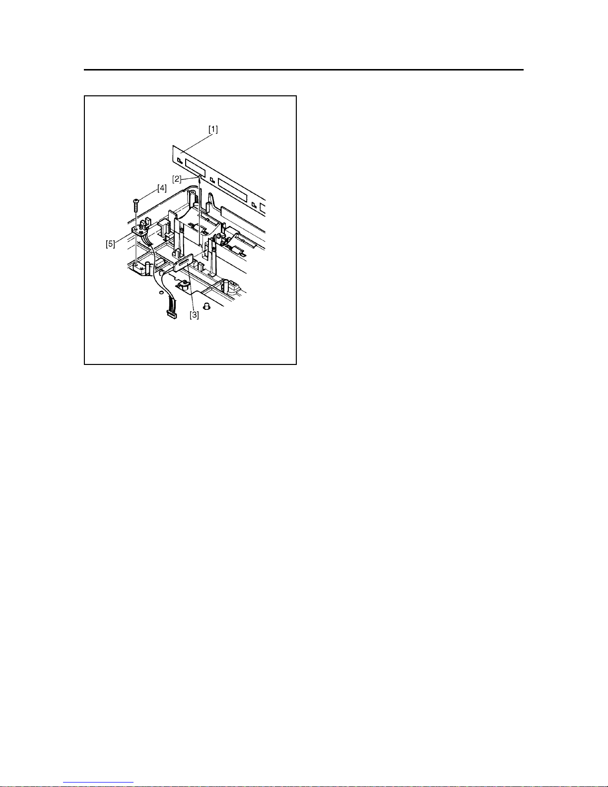
10. Detector Unit
(1) Remove
• Printer mechanism according to the procedure
described in item 2.
• Cord fastener binding the lead wires
• Sub guide [1]
Lift the notched part [2] and slide sub guide [1]
to the left to remove.
• PE detector [3]
• Screw [4]
• Home position detector [5]
Page 48

CHAPTER 5
MAINTENANCE AND LUBRICATION
1. Maintenance ........................................................................................................ 47
1-1. Cleaning ................................................................................................................. 47
1-2. Checks ................................................................................................................... 47
2. Lubrication...........................................................................................................48
2-1. Lubricant................................................................................................................ 48
2-2. Lubricating Method ............................................................................................... 48
2-3. Lubricated Areas................................................................................................... 48
1
2
3
4
5
6
7
8
A
Page 49

– 46 –
Page 50

– 47 –
MAINTENANCE AND LUBRICATION
1. Maintenance
In order to maintain the optimum performance of this printer and to prevent trouble, maintenance must be carried out
according to the following items.
1-1. Cleaning
(1) Removal of dirt
Wipe off dirt with a soft cloth soaked in alcohol or benzine.
*Note: Do not use thinner, trichlene or ketone solvents because they may damage plastic parts. Also during
cleaning, be careful not to moisten or damage electronic parts, wiring, or mechanical parts.
(2) Removal of dust, pile, etc.
Vacuum cleaning (with an electric cleaner) is preferred. Remove all dust, etc., inside the printer.
*Note: After cleaning, check the oil level. If it is not adequate due to cleaning, replenish it.
1-2. Checks
Checks must be carried out at two levels: “daily check” which the operator can easily carry out during operation, and
“periodic check” which an expert should carry out.
(1) Daily check
When the printer is used on a daily basis, check to be sure that the printer is being used properly. Make sure that
the printer is operating under the best conditions.
• Is any paper stuck in the paper box or printer case?
• Is the cartridge ribbon set to the right position?
• Is there any foreign matter inside the printer? (Remove.)
• Is the print head getting excessively dirty?
(2) Periodic check
After 6 months or printing 1,000,000 lines, the periodic check and lubrication must be carried out.
• Check for deformation of springs.
• Check the gap between the platen and the print head.
• Remove dust, dirt, etc., from near each detector.
Page 51

– 48 –
MAINTENANCE AND LUBRICATION
2. Lubrication
Lubrication is very important to maintain optimum performance and to prevent trouble.
2-1. Lubricant
The type of lubricant greatly affects the performance and durability of the printer, especially in a low temperature
environment. We recommend use of the grease and lubrication oils listed below for this printer
Product name Maker
FLOIL GB-TS-0 and FLOIL GB-100 Kanto Chemicals Co., Ltd.
KF96-1000CS and KF96-SP Shinetsu Chemical Industry
Mobil 1 Mobil oil
2-2. Lubricating Method
When lubrication is carried out in assembly and disassembly, wash parts well to remove dust and dirt before lubrication.
Lubrication must be carried out regularly once every 6 months or after 1 million lines have been printed. Lubrication is
necessary irrespective of the regular lubrication whenever lubricant becomes deficient after cleaning or whenever parts
have been disassembled or replaced.
2-3. Lubricated Areas
NO. Lubrication Product Name
[1] Rubbing surfaces of idler gear 16 × 72 × 0.5 and idler gear shaft GB-TS-0
[2] Rubbing surfaces of gear 40 × 0.5 and gear shaft GB-TS-0
[3] Rubbing surfaces of adjusting lever and frame GB-TS-0
[4] Rubbing surfaces of timing pulley and pulley shaft GB-TS-0
[5] Rubbing surfaces of rear angle and carriage GB-TS-0
[6] Rubbing surfaces of bushing and carriage stay Mobil 1
[7] Rubbing surfaces of timing pulley and stop ring GB-TS-0
[8] Rubbing surfaces of release shaft and frame GB-TS-0
[9] Rubbing surfaces of release lever and tractor shaft GB-TS-0
[10] Rubbing surfaces of two tractor bushings and tractor shaft GB-TS-0
[11] Rubbing surfaces of tractor holder and tractor cover KF96-1000CS
[12] Rubbing surfaces of bail roller and shaft KF96-SP
[13] Rubbing surfaces of timing pulley and pulley bushing GB-100
[14] Rubbing surfaces of lift cam and ribbon change lever GB-TS-0
[15] Rubbing surfaces of lift cam and carriage shaft GB-TS-0
[16] Rubbing surfaces of ribbon change lever and carriage KF96-1000CS
[17] Rubbing surfaces of idler gear 16 × 1 – 40 × 0.3 GB-TS-0
[18] Rubbing surfaces of lift lever assy and carriage shaft KF96-1000CS
[19] Rubbing surfaces of lift lever assy and carriage GB-TS-0
[20] Rubbing surfaces of lift lever assy and lift cam KF96-1000CS
[21] Rubbing surfaces of ribbon cassette gear and carriage shaft GB-TS-0
[22] Rubbing surfaces of rear angle and idler gear 16 × 1 – 40 × 0.3 GB-TS-0
[23] Rubbing surfaces of idler gear 43 × 6.3 × 0.3 and carriage shaft GB-TS-0
[24] Rubbing surfaces of idler 43 × 6.3 × 0.3 and gear cover GB-TS-0
[25] Rubbing surfaces of idler gear 17 × 41 × 0.3 and clutch lever GB-TS-0
[26] Rubbing surfaces of idler gear 16 × 1 – 40 × 0.3 and carriage shaft GB-TS-0
[27] Rubbing surfaces of lift cam and gear cover GB-TS-0
[28] Rubbing surfaces of wave washer and poly-slider GB-TS-0
Page 52

– 49 –
MAINTENANCE AND LUBRICATION
Fig. 5-1 Lubricated Areas
Detail-B (Monochrome Type)
Detail-B (Colour Type)
Page 53

– 50 –
Page 54

– 51 –
CHAPTER 6
TROUBLESHOOTING
1. Troubleshooting Procedures ............................................................................. 53
2. Unit Replacement Flow Chart ............................................................................ 54
3. Repair by Unit Replacement .............................................................................. 55
4. Repair by Replacement of Parts ........................................................................ 61
4-1 Does not Operate at ALL with Power on.............................................................61
4-2 Power Supply Unit Abnormal...............................................................................62
4-3 Defective Motor Operation ................................................................................... 63
4-4 Defective Print Head Operation ........................................................................... 64
4-5 Defective Interface Operation .............................................................................. 65
1
2
3
4
5
6
7
8
A
Page 55

– 58 –
REPLACEMENT AND ADJUSTMENT OF PARTS
Page 56

– 53 –
TROUBLESHOOTING
1. Troubleshooting Procedures
Troubleshooting is never easy because various problems arise depending upon the particular location of the breakdown,
but the following procedures should be adhered to in making repairs.
(1) At the first stage, conduct repairs through unit replacements.
The two display codes appearing in the flow chart are defined as follows: 1) indicates main logic board replacement
and 2) indicates printer mechanism replacement, to be carried out if the problem has not been corrected.
1) Main Logic Board Replacement
2) Printer Mechanism Replacement
Check again at this time whether the replaced unit is malfunctioning. (This is done to rule out trouble caused by improper
contact of connectors.)
Replaceable units consist of the following:
• Power supply unit
• Main logic board
• Printer mechanism
In replacing these units, always refer to the unit replacement flow chart.
(2) At the second stage, use the flow chart for repair by parts replacement to replace defective elements inside a
particular unit.
(Note 1) Before starting to repair, be sure to check visually the contact of the connector and the mounting of the IC
in the IC socket.
(Note 2) Always turn off power source and remove power plug before replacing any units or parts.
(Note 3) If any check items appear on the flow chart, be sure to always check them. Otherwise, newly mounted parts
or units may become damaged.
(Note 4) If, in the process of making repairs, there is any confusion about proper procedures, start to do the job again
from the beginning.
(Note 5) Refer to the oscilloscope waveforms presented in Chapter 7 when repairing boards.
(Note 6) Be careful to avoid injury from static electricity when handling ICs and main logic boards.
(3) The following relate to the “*” marks in the flow chart.
*1 See (6) and (7) waveform in Item 7 of Chapter 7 or Chapter 8 and Fig. 2-10 ~ 17 in Chapter 2.
*2 See (8) and (9) waveform in Item 7 of Chapter 7 or Chapter 8.
*3 See (4) and (5) waveform in Item 7 of Chapter 7 or Chapter 8.
*4 See 3. Power Supply unit in Chapter 2.
*5 See 2-1. Data Input Operation in Chapter 2 and (10) or (11) waveform in Item 7 of Chapter 7 or Chapter 8.
*6 See (2) RESET waveform in Item 7 of Chapter 7 or Chapter 8.
*7 See (1) Crystal waveform in Item 7 of Chapter 7 or Chapter 8.
Page 57

– 54 –
TROUBLESHOOTING
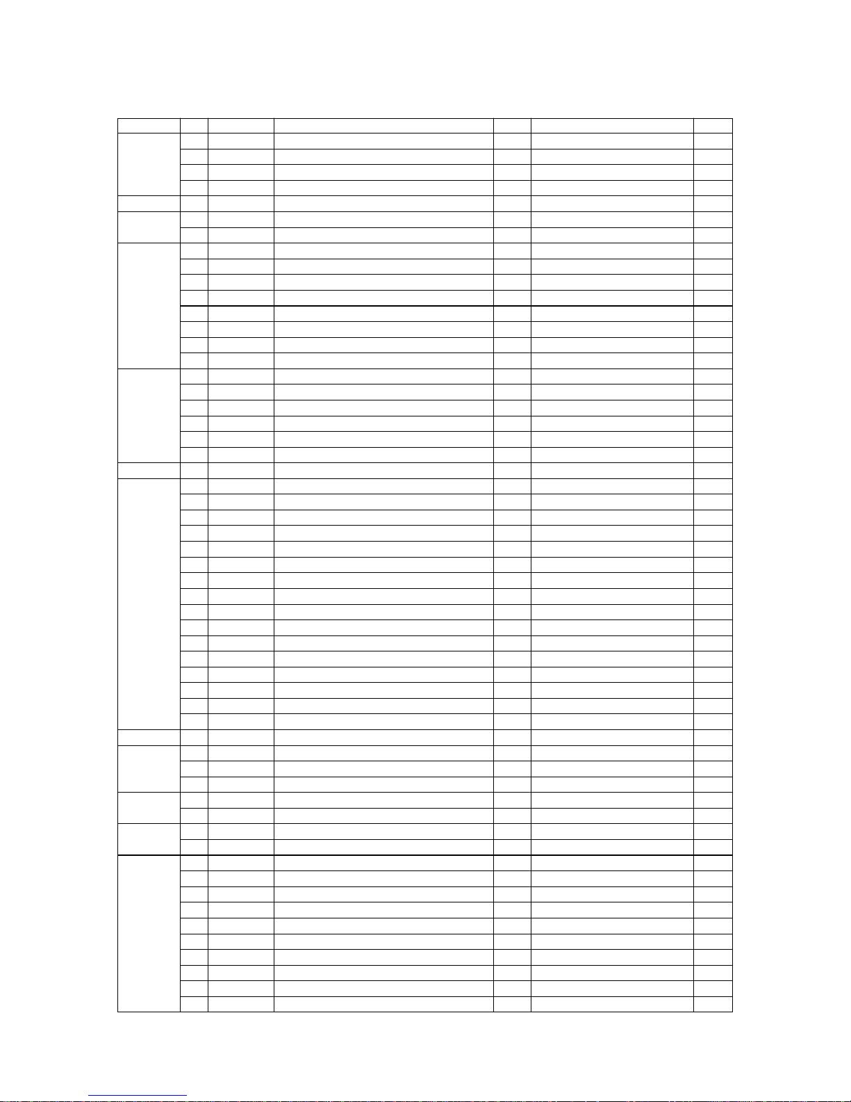
2. Unit Replacement Flow Chart
Unit Exchange Sequence
Power
supply unit
Problem
Details
Category Remarks
Specific display
lamp only will
not glow
Specific switch
only cannot be
input
Buzzer does not
sound (sound
volume
inadequate)
Strange sounds
during operation
No motor
holding power
(power very
weak)
Dots skipped
Print is too light
Ink ribbon
entanglement
(wire sticks out)
Absence of paper
not detected
Lever position
not detected
Incorrect printing
Ink ribbon not
forwarded
No operation at
DIP switch
setting
Faulty operation
when power is
turned on/off
Abnormal motor
operating speed
(slow)
Fuse blown
during operation
2
3
Ink ribbon
Gap check
Check I/F cable
Note: The figures 1, 2 and 3 mean the priority of replacement.
Operation related
Motor related
Print head
related
Detector
related
Interface related and others
Printer
mechanism
2
1
1
1
1
2
1
2
2
1
1
1
1
1
2
2
2
2
1
1
1
1
1
1
Main
logic board
Check setting of
DIP switch
Page 58

– 55 –
TROUBLESHOOTING
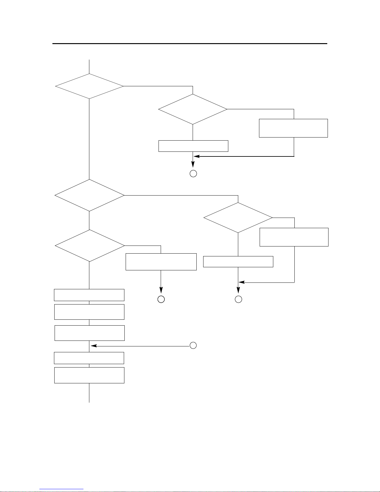
3. Repair by Unit Replacement
1) Replace main logic
board.
2) Replace printer
mechanism.
Carriage motor
operating waveform is
normal? *1
YES
Replace printer mechanism.
A
NO
NO
A
NO
1) Replace main logic
board.
2) Replace printer
mechanism.
A
NO
NO
Home position
switch signal is
normal?
YES
Replace main logic board.
START
* Turn power off.
* Remove I/F cable.
* Mount ink ribbon.
* Set paper.
* Move carriage to center.
Turn power on.
Carriage
Movement?
YES
Carriage operates
normally?
YES
Carriage stops at
home position?
YES
B
Page 59

– 56 –
TROUBLESHOOTING
1) Replace main logic board.
2) Replace printer mechanism.
NO
1) Replace main logic board.
2) Replace printer mechanism.
A
NO
NO
Paper feed
motor drive waveform
is normal? *2
YES
Replace printer mechanism.
A
Self
printing:
Carriage motor
drive waveform is
normal? *1
YES
Replace printer mechanism.
Printer lamps light?
YES
On line switch in on.
(Take Off Line)
On line lamp is out?
YES
Paper feed switch is on.
Paper feed switch
operation is normal?
YES
Power is off.
Power source is on while
pressing paper feed switch.
Carriage operates
normally?
YES
NO
NO
NO
Replace main logic board.
A
Replace main
logic board.
Page 60
– 57 –
TROUBLESHOOTING
1) Replace main logic board.
2) Replace printer mechanism.
A
NO
Print head
drive signal waveform is
normal? *3
YES
Replace printer mechanism.
NO
C
NO
1) Replace main logic board.
2) Replace printer mechanism.
NO
NO
1) Replace ink ribbon.
2) Replace printer mechanism.
AA
A
Replace printer mechanism.
Paper feed
motor drive waveform is
normal? *2
YES
Printing operation
is normal?
YES
Paper feed
operation is
normal?
YES
Ribbon feed
operation is
normal?
YES
Self printing terminates.
Check host computer
connection.
Power is off and I/F cable is
connected.
Power is on.
Print program operation
begins from host computer.
Page 61
– 58 –
TROUBLESHOOTING
1) Replace I/F cable.
2) Replace main logic board.
3) Check host computer.
Replace printer mechanism.
Replace power supply unit.
C
D
NO
NO
NO
YES
NO
Printing begins?
YES
Printing
operation normal?
YES
Printer is normal; host
computer print program stops.
END
Works with
carriage hand?
YES
Output
(+24V, +5V)
of power supply unit is
normal? *4
NO
Power source is off.
Fuse blows out?
YES
Replace fuse.
Remove connector CN5[CN6]
of main logic board.
Power source is on.
B
[ ]: Commodore type
1) Replace main logic board.
2) Replace printer
mechanism.
A
Page 62

– 59 –
TROUBLESHOOTING
NO
NO
A
[ ]: Commodore type
Output of
power supply unit is
normal? *4
YES
Power source is off.
Connect connector
CN5[CN6] of
main logic board.
Power source is on.
Fuse blows out?
YES
Replace fuse
1) Replace main logic board.
2) Replace printer mechanism.
Page 63

– 60 –
TROUBLESHOOTING
YES
NO
YES
YES
1) Replace I/F cable.
2) Replace main logic board.
D
NO
NO
E
A
C
A
I/F signal is
normal? *5
NO
Ready condition?
YES
There is data
transmission?
NO
Hardware check or check
of host computer print
program.
On line switch
goes ON/OFF?
YES
On line lamp
drive signal is
normal?
YES
Replace main logic board.
I/F mode set
up properly?
NO
I/F mode set up changed.
① Replace control panel board.
➁ Replace main logic board.
Page 64

– 61 –
TROUBLESHOOTING
4. Repair by Replacement of Parts
4-1. Does not Operate at All with Power on
DC Power abnormal.
Check RESET circuit;
replace parts.
Check crystal circuit;
replace parts.
1) Replace CPU or ROM.
2) Check relevant circuit.
NO
NO
NO
NO
See 4-2. Power Supply
Unit Abnormal.
START
+24V
and +5V are
supplied? *4
YES
RESET
signal becomes
HIGH? *6
YES
Crystal
waveform is
normal? *1
YES
ROM OE
signals become
LOW?
YES
Carriage motor abnormal.
Check operation.
END
Page 65

– 62 –
TROUBLESHOOTING
4-2. Power Supply Circuit Abnormal
(1) Remove connector CN5 (CN6 for Commodore type) of the main logic board.
YES
Replace Fuse F1
Fuse is
blown again?
NO
START
Fuse F1
is blown?
NO
Fuse F2 or F3
is blown?
NO
Check operation.
END
Replace
1) Transformer
2) IC1
YES
F3 is for AC120 only
YES
YES
YES
NO
Replace
Fuse F2 or F3
Fuse is
blown again?
NO
ACS1
and ACS2 are
supplied?
NO
Replace
transformer
The no load voltages are below:
ACS2 AC29.9V
ACS1 AC8.5V
Check or replace
1) D1~D4
2) IC1
NO
Check or replace
1) DB1
2) TR1, TR3
+5V line
is supplied?
YES
+24V line
is supplied?
YES
Page 66

– 63 –
TROUBLESHOOTING
4-3. Defective Motor Operation
NO
NO
NO
NO
START
START
LF-CMN
signal is normal?
*2
YES
LF-ø1,
ø2, ø3, ø4 are
normal? *2
YES
Replace
LF-motor
Check operation
END
Check or replace
1) TR1(TR202)
2) TR6(TR5)
3) CPU
Check or replace
1) TA1(TA201)
2) CPU
CR-CMN
signal is normal?
*1
YES
CR-ø1,
ø2, ø3, ø4 are
normal? *1
YES
Replace
CR-motor
Check operation
END
Check or replace
1) TR2(TR201)
2) TR7(TR4)
3) CPU
Check or replace
1) TA2(TA202)
2) CPU
( ): Ver. 1.5 and Ver. 2
( ): Ver. 1.5 and Ver. 2
( ): Ver. 1.5 and Ver. 2
( ): Ver. 1.5 and Ver. 2
Page 67
– 64 –
TROUBLESHOOTING
4-4. Defective Print Head Operation
Check or replace
1) TR8~TR16
(TR6~TR14)
Adjust gap
(Refer to chapter 3.)
Power supply
unit abnormal.
(Refer to item 4-2.)
Check or replace
1) Gate array
2) CPU
YES
YES
( ): Ver. 1.5 and Ver. 2
( ): Ver. 1.5 and Ver. 2
START
Does not
print at all?
YES
+24V
line is
supplied?
YES
Check or replace
1) TR4(TR1)
2) Gate array
Head
energizing control
signal is normal?
*3
YES
Check or replace
1) Print mechanism
END
NO
NO
NO
A specific
pin does not
work?
NO
Print is light
as whole?
NO
Page 68
– 65 –
TROUBLESHOOTING
4-5. Defective Interface Operation
NO
YES
START
Set at on line
Start print program
of host computer.
Is I/F
signal normal? *5
YES
Incorrect print
generated?
NO
Check operation
END
Check I/F cable.
Check or replace
1) IC2 (IC5)[IC1]
2) Gate array
3) CPU
( ) : Ver. 1.5 and Ver. 2
[ ] : Commodore type
Page 69

– 66 –
Page 70

CHAPTER 7
PARTS LIST (For Ver. 1 and Ver. 1.5)
HOW TO USE PARTS LIST
(1) DRWG. NO.
This column shows the drawing number of the illustration.
(2) REVISED EDITION MARK
This column shows a revision number.
Part that have been added in the revised edition are indicated with “#”.
Part that have been abolished in the revised edition are indicated with “*”. For example,
#1 :First edition→Second edition *1 :First edition→Second edition
(3) PARTS NO.
Parts numbers must be indicated when ordering replacement parts.
(4) PARTS NAME
Parts names must be indicated when ordering replacement parts.
(5) Q’TY
This column shows the number of the part used as indicated in the figure.
(6) REMARKS
When there are differences in the specifications of the fuse, destinations, etc., the differences are described in
words or indicated by two letters.
US ..........U.S.A. EC ....... EC (220V) AS .............Australia
MAS .......Mass Merchant WG ...... Germany NBR..........No Brand
(NX MALTI TYPE) SC ........ Scandinavia SU .............Russia
TW .........Taiwan HK....... Hong Kong MONO......Monochrome
UE ..........EC (120V) UK ....... United Kingdom CL.............Color Type
The seal number of ROM is described in this column. The “**” mark of a seal number is variable depending
on the software version.
(7) RANK
Parts marked “S” are service parts. Service parts are recommendable for maintenance.
1. Pringer Assembly............................. 68
1-1. Disassembly Drawing....................68
1-2. Parts List......................................... 69
2. Printer Mechanism ............................. 71
2-1. Disassembly Drawing....................71
2-2. Parts List......................................... 72
3. Sub-Assembly .................................. 73
3-1. Upper Case Unit ............................. 73
3-2. Lower Case Unit.............................74
3-3. Frame Unit ...................................... 75
3-3-1. Monochrome Type ................ 75
3-3-2. Colour Type ........................... 76
3-4. Tractor Unit..................................... 78
3-5. Platen Unit ...................................... 79
4. Wiring Scheme of Printer ................ 80
4-1. Parallel Type................................... 80
4-2. Commodore Type .......................... 81
5. Main Logic Board ............................. 82
5-1. Parallel Type (Ver.1)....................... 82
5-1-1. Component Layout................ 82
5-1-2. Parts List ................................ 84
5-1-3. Circuit Diagram...................... 88
5-2. Parallel Type (Ver.1.5).................... 92
5-2-1. Component Layout................ 92
5-2-2. Parts List ................................ 94
5-2-3. Circuit Diagram...................... 98
5-3. Commodore Type ........................ 102
5-3-1. Component Layout.............. 102
5-3-2. Parts List .............................. 104
5-3-3. Circuit Diagram.................... 106
6. Power Supply Unit ......................... 110
6-1. Circuit Diagram ............................ 110
6-2. Component Layout ...................... 110
6-3. Parts List....................................... 111
7. Waveform with Oscilloscope ........ 112
1
2
3
4
5
6
7
8
A
Page 71

– 68 –
1. Printer Assembly (Ver. 1 and 1.5)
1-1. Disassembly Drawing
Page 72
– 69 –
1-2. Parts List Printer Assembly (Ver .1 and 1.5)
Printer Assembly (Ver. 1 and 1.5)
DRWG.NO. REV. PARTS NO. PARTS NAME Q'TY REMARKS RANK
1 89060010 PRINTER MECHANISM DP891 1 FOR MONO(VER.1.0) S
#2 89060050 PRINTER MECHANISM DP891D 1 FOR MONO(VER.1.5) S
#1 89060020 PRINTER MECHANISM DP891CL 1 FOR CL(VER.1.0) S
#2 89060060 PRINTER MECHANISM DP891DCL 1 FOR CL(VER.1.5) S
2 89130010 PRINT HEAD DP8901 1 S
3 87291010 LOWER CASE UNIT NX-1000 1 FOR VER.1.0 S
#2 87291050 LOWER CASE UNIT NX-1000D 1 FOR VER.1.5 S
4 87292010 MAIN LOGIC BOARD UNIT NX-1000 1 MONO(1.1),PARALLEL S
#2 87292090 MAIN LOGIC BOARD UNIT NX-1000D 1 MONO(1.5),PA. EX. HK S
#3 87292110 MAIN LOGIC BD UNIT NX-1000D HK 1 MONO(1.5),PA. FOR HK S
#1 87292030 MAIN LOGIC BOARD UNIT NX1000CL 1 CL(1.0),PARALLEL S
#2 87292100 MAIN LOGIC BD UNIT NX-1000DCL 1 CL(1.5),PA. EX. HK S
#3 87292140 MAIN LOGIC BD UNIT NX1000DCLHK 1 CL(1.5),PA. FOR HK S
87292020 MAIN LOGIC BOARD UNIT NX-1000C 1 FOR MONO,COMMODORE S
#1 87292040 MAIN LOGIC BD UNIT NX-1000C CL 1 FOR CL,COMMODORE S
5 87293060 POWER SUPPLY UNIT NX-1000 US 1 FOR US,UE,TW,MAS S
87293070 POWER SUPPLY UNIT NX-1000 EC 1 FOR EC,WG,NBR,SU S
87293100 POWER SUPPLY UNIT NX-1000 HK 1 FOR HK S
#2 87293180 POWER SUPPLY UNIT NX-1000 SC 1 FOR SC S
87293080 POWER SUPPLY UNIT NX-1000 UK 1 FOR UK S
87293090 POWER SUPPLY UNIT NX-1000 AS 1 FOR AS S
6 82040070 SUB-GUIDE 891 1 S
7 #2 87290160 UPPER CASE UNIT NX-1000 MAS 1 FOR MAS :NX-1000 S
87290010 UPPER CASE UNIT NX-1000 1 EXCEPT MAS :NX-1000 S
87290080 UPPER CASE UNIT LC-10NBR 1 FOR NBR :LC-10 S
87290030 UPPER CASE UNIT LC-10 1 EXCEPT FOR NBR:LC-10 S
87290020 UPPER CASE UNIT NX-1000C 1 :NX-1000C S
87290080 UPPER CASE UNIT LC-10NBR 1 FOR NBR :LC-10C S
87290040 UPPER CASE UNIT LC-10C 1 EXCEPT NBR :LC-10C S
#1 87290050 UPPER CASE UNIT NX-1000CL US 1 FOR US :NX-1000CL S
#2 87290170 UPPER CASE UNIT NX-1000CL MAS 1 FOR MAS :NX-1000CL S
#1 87290070 UPPER CASE UNIT NX-1000 CL 1 TW,HK,AS :NX-1000CL S
#4 87290390 UPPER CASE UNIT NX-1000CL SU 1 FOR SU :NX-1000CL S
#1 87290120 UPPER CASE UNIT LC-10CL NBR 1 FOR NBR :LC-10CL S
#1 87290060 UPPER CASE UNIT LC-10CL 1 EXCEPT NBR :LC-10CL S
#1 87290090 UPPER CASE UNIT NX-1000C CL US 1 FOR US :NX-1000CCL S
#1 87290100 UPPER CASE UNIT NX-1000C CL 1 FOR HK,AS:NX-1000CCL S
#1 87290110 UPPER CASE UNIT LC-10C CL 1 :LC-10CCL S
8 83022890 PRINTER COVER NX-1000 1 S
9 *2 87296010 PAPER GUIDE UNIT NX-1000 1 S
*6 87296011 PAPER GUIDE UNIT NX-1000 1 S
#6 87806010 PAPER GUIDE UNIT ZL-10 1 S
10 *6 83022900 REAR COVER NX-1000 1 S
#6 83022901 REAR COVER NX-1000 1 S
11 *6 83120460 PLATEN KNOB NX-1000 1 S
#6 83903910 PLATEN KNOB QA-10 1 S
12 *3 80980730 INK RIBBON CARTRIDGE WHT LC9 1 EXCEPT FOR NBR :MONO S
*7 80981160 INK RIBBON CARTRIDGE JA NX1000 1 EXCEPT US,NBR :MONO S
#7 80982290 INK RIBBON CARTRIDGE JAN LC9 1 EXCEPT US,NBR :MONO S
#3 80980850 INK RIBBON CARTRIDGE UPC LC9 1 FOR US :MONO S
*7 80980800 INK RIBBON CARTRIDGE NX1000NBR 1 FOR NBR :MONO S
#7 80980730 INK RIBBON CARTRIDGE WHT LC9 1 FOR NBR :MONO S
*3 80980740 INK RIBBON CARTRIDGE NX-1000CL 1 EXCEPT FOR NBR :CL S
*7 80981170 INK RIBBON CARTRIDGE JAN NX-CL 1 EXCEPT US,NBR,AS :CL S
#7 80982340 INK RIBBON CARTRIDGE JAN LC9CL 1 EXCEPT US,NBR,AS :CL S
*7 80981360 INK RIBBON CARTRIDGE UPC NX-CL 1 FOR US :CL S
Page 73

– 70 –
12
16 *1 82900770 RIBBON HOLDER 891 1 FOR MONO S
*2 82900771 RIBBON HOLDER 891 1 FOR MONO S
*4 82900772 RIBBON HOLDER 891 1 FOR MONO S
#4 82900773 RIBBON HOLDER 891 1 FOR MONO S
#1 82901010 RIBBON HOLDER 891CL 1 FOR CL S
17 80991760 INSULATION SHEET NX-1000 1 S
18 01902612 SCREW TAT 2.6-16 PT 2 S
19 01903060 SCREW TAT 3-8 PT-FL 2 S
20 *1 01903055 SCREW TR 3-8 WS/WF 2 S
*2 01903045 SCREW TR 3-8 FL 2 S
#2 01903070 SCREW TR 3-8 WF 2 S
21 #2 01704103 SCREW TRHT 4-10-C 1 FOR US,MAS S
01914007 SCREW TR 4-8 WB 2 EXCEPT FOR US,MAS S
22 01914030 SCREW TAT 4-15 PT 4 S
23 01914031 SCREW TAT 4-12 PT-FL 4 S
24 *1 01914029 SCREW TAT 4-8 CT-WB 4 S
*4 01914032 SCREW TAT 4-7 CT 4 S
*5 01914039 SCREW TAT 4-8 WS 1 S
#5 01914034 SCREW TAT 4-8 CT-WF 1 S
25 04020016 STOP RING SE4.0 1 S
26 *2 80924910 WIRE 18UL1007G/Y100T 1 S
#2 80924911 WIRE 18UL1007BLK100TT 1 S
27 80924440 INTERFACE CABLE COMMODORE 1 FOR COMMODORE ONLY S
28 #2 01903071 SCREW TATH 3-10C1P 1 FOR US,MAS S
#2 01903060 SCREW TAT 3-8 PT-FL 1 EXCEPT FOR US,MAS S
29 #4 01914036 SCREW TR 4-5 WS 2 FOR HK S
#4 01914014 SCREW TR 4-5 WB 3 FOR US,MAS S
#4 01914036 SCREW TR 4-5 WS 3 EXCEPT FOR HK,US,MAS S
- #2 89590090 ASF SF-10DJ UK 1 FOR UK,EC,SC,TW :OP.
#3 89590093 ASF SF-10DJ US 1 FOR US,MAS :OPTION
#2 89590091 ASF SF-10DJ WG 1 FOR WG :OPTION
#5 89590095 ASF SF-10DJ AS 1 FOR AS :OPTION
#4 89590096 ASF SF-10DJ HK 1 FOR HK,SU :OPTION
#7 80982330 INK RIBBON CARTRIDGE UPC LC9CL 1 FOR US :CL S
*7 80980810 INK RIBBON CARTRIDGE NX1000CLN 1 FOR NBR :CL S
#7 80982360 INK RIBBON CARTRIDGE WHT LC9CL 1 FOR NBR :CL S
#5 80982340 INK RIBBON CARTRIDGE JAN LC9CL 1 FOR AS :CL S
13 83400450 RELEASE LEVER 891 1 S
14 87295020 RELEASE SHAFT UNIT NX-1000 1 S
15 *4 83910840 CABLE HOLDER 891 1 S
#4 83910841 CABLE HOLDER 941 1 S
Printer Assembly (Ver. 1 and 1.5)
DRWG.NO. REV. PARTS NO. PARTS NAME Q'TY REMARKS RANK
Page 74

– 71 –
2. Printer Mechanism (Ver. 1 and 1.5)
2-1. Disassembly Drawing
Page 75

– 72 –
2-2. Parts List
Printer Mechanism (Ver. 1 and 1.5)
DRWG.NO. REV. PARTS NO. PARTS NAME Q'TY REMARKS RANK
1 87060010 FRAME UNIT 891 1 FOR MONO(VER.1.0)
#2 87060050 FRAME UNIT 891D 1 FOR MONO(VER.1.5)
#1 87060020 FRAME UNIT 891CL 1 FOR CL(VER.1.0)
#2 87060070 FRAME UNIT 891DCL 1 FOR CL(VER.1.5)
2 87061010 CARRIAGE MOTOR UNIT 891 1 FOR MONO(VER.1.0) S
#2 87061060 CARRIAGE MOTOR UNIT 891D 1 FOR MONO(VER.1.5) S
#1 87061030 CARRIAGE MOTOR UNIT 891CL 1 FOR CL(VER.1.0) S
#2 87061100 CARRIAGE MOTOR UNIT 891DCL 1 FOR CL(VER.1.5) S
3 87067020 BAIL ROLLER SHAFT UNIT 891 1
4 83400440 BAIL LEVER R 891 1 S
5 83400460 BAIL LEVER L 891 1 S
6 87063010 PLATEN UNIT 891 1 S
7 *1 81370520 TRACTOR STAY 891 1
*5 81370521 TRACTOR STAY 891 1
#5 81370522 TRACTOR STAY 891 1
8 87066010 TRACTOR UNIT 891 1 S
9 87067010 TENSION LEVER UNIT 891 1
10 87065010 DETECTOR UNIT 891 1 S
11 82400960 ADJUSTING LEVER 891 1
12 04991229 VINYL CAP D2X5 1
13 80530510 BAIL LEVER SPRING 891 2 S
14 *2 80530530 GROUND CONTACT SPRING 891 1 S
*4 80530570 GROUND CONTACT SPRING 921 1 S
#4 80530571 GROUND CONTACT SPRING 921 1 S
15 *2 00820404 SCREW TR 2-4 2 FOR TAPPED HOLE S
*4 00920503 SCREW TAT 2-5 CT 2 FOR NON-TAPPED HOLE S
#4 00926603 SCREW TAT 2.6-6 CT 2 FOR NON-TAPPED HOLE S
16 *2 00630404 SCREW TR 3-4 2 S
#2 01903064 SCREW TAT 3-5 CT 2 S
17 01903018 SCREW TR 3-6 WS/WF 1 S
18 #1 02040402 FLANGED NUT NHW4 1 S
19 *5 02040403 TOOTHED NUT NHK4 4 S
#5 02020401 HEXAGON NUT NH4-2 4 S
20 #4 87060340 CARRIAGE ASSY 891 1 FOR MONO(VER.1.0)
#4 87060341 CARRIAGE ASSY 891B 1 FOR MONO(VER.1.5)
#4 87060350 CARRIAGE ASSY 891CL 1 FOR CL(VER.1.0)
#4 87060440 CARRIAGE ASSY 891DCL 1 FOR CL(VER.1.5)
- 04991204 FASTENER T18S 2 S
*2 04991228 MINI CORD CLAMP UAMS-05-2 4 S
#2 04991230 MINI CORD CLAMP UAMS-05-SN 4 S
Page 76
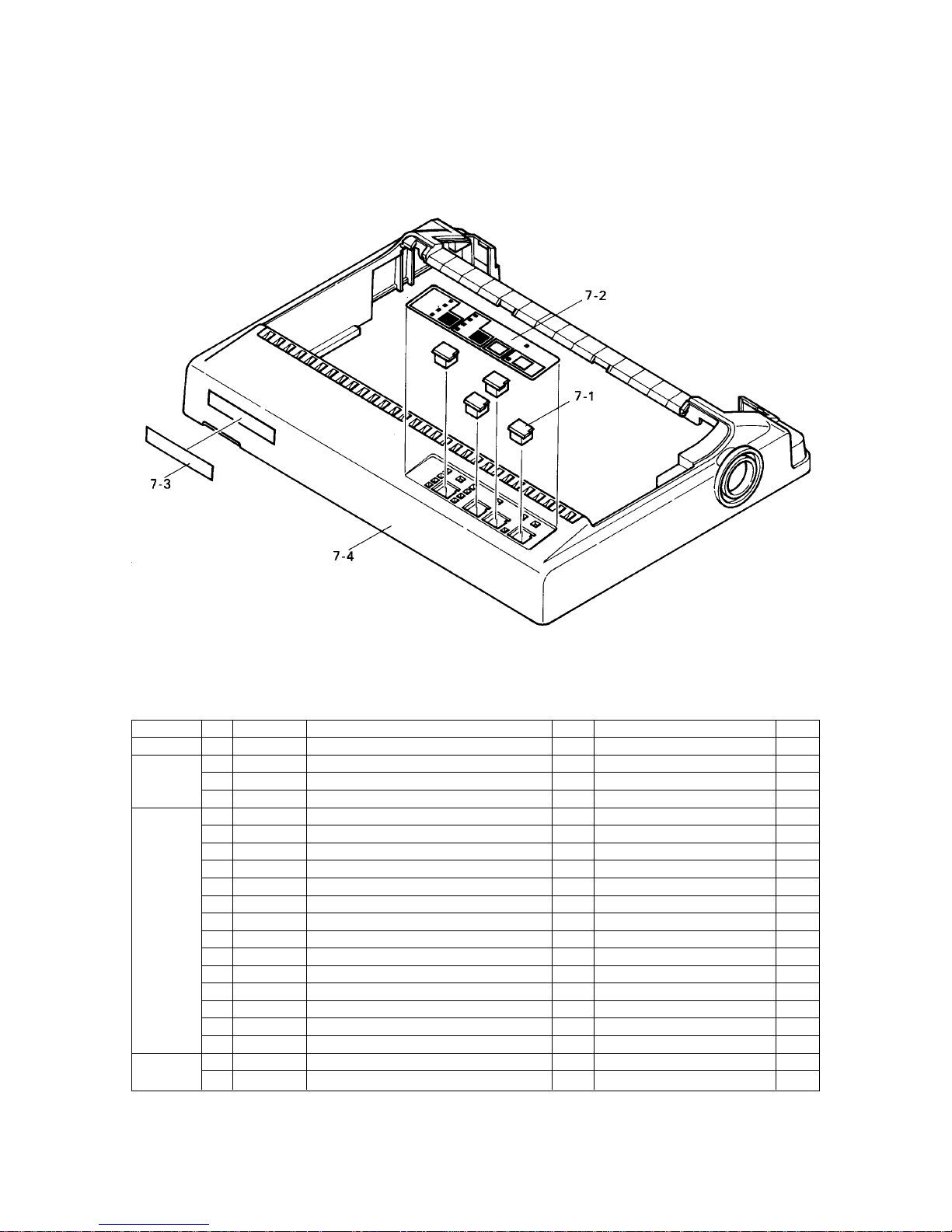
– 73 –
7-1 83901660 SWITCH ACTUATOR NX-1000 4 S
7-2 80085780 OPERATION SHEET NX-1000 1 FOR MONO S
#1 80085900 OPERATION SHEET NX-1000CL 1 FOR CL S
#4 80086020 OPERATION SHEET SPECIAL LC10CL 1 FOR SU S
7-3 #2 80081870 BRAND PLATE NX MULTI-TYPE 1 FOR MAS :NX-1000 S
80081210 BRAND SEAL NX-1000 1 EXCEPT MAS :NX-1000 S
80081290 BRAND SEAL LC-10 1 :LC-10 S
80081220 BRAND SEAL NX-1000C 1 :NX-1000C S
80081300 BRAND SEAL LC-10C 1 :LC-10C S
#1 80081270 BRAND PLATE NX-1000 RAINBOW 1 FOR US,SU :NX-1000CL S
#2 80081880 BRAND PLATE NX MULTI-COLOR 1 FOR MAS :NX-1000CL S
#1 80081310 BRAND PLATE NX-1000 COLOUR 1 TW,HK,AS :NX-1000CL S
*6 80081280 BRAND PLATE LC-10 CL 1 :LC-10CL S
#6 80081281 BRAND PLATE LC-10 CL 1 :LC-10CL S
#1 80081340 BRAND PLATE NX-1000C RAINBOW 1 FOR US :NX-1000CCL S
#1 80081350 BRAND PLATE NX-1000C COLOUR 1 FOR HK,AS:NX-1000CCL S
#1 80081360 BRAND PLATE LC-10C CL 1 :LC-10CCL S
NOT MOUNTED :FOR NBR
7-4 *6 83022880 UPPER CASE NX-1000 1
#6 83022881 UPPER CASE NX-1000 1
3. Sub-assembly (Ver. 1 and 1.5)
3-1. Upper Case Unit
DRWG.NO. REV. PARTS NO. PARTS NAME Q'TY REMARKS RANK
Upper Case Unit (Ver. 1 and 1.5)
Page 77

– 74 –
3-1 *6 83022910 LOWER CASE NX-1000 1
#6 83022911 LOWER CASE NX-1000 1
3-2 *3 82010760 LOWER CASE CHASSIS NX-1000 1
#3 82010761 LOWER CASE CHASSIS NX-1000 1
3-3 83200640 HOLDER ROLLER 891 3 S
3-4 81301320 ROLLER SHAFT 891 3 S
3-5 87291320 DETECTOR UNIT NX-1000 1 FOR VER.1.0 S
#2 87291330 DETECTOR UNIT A NX-1000D 1 FOR VER.1.5 S
3-6 87291310 PE DETECTOR LEVER ASSY NX-1000 1
3-7 82500810 RELEASE SPRING 891 3 S
3-8 80510700 SPRING E030-014-0088 1 S
3-9 *5 01903064 SCREW TAT 3-5 CT 1 S
#5 01903094 SCREW TAT 3-5 DT 1 S
3-10 00930803 SCREW TAT 3-8 PT 3 S
3-11 01903047 SCREW TAT 3-12 PT-FL 1 S
3-12 80991800 BLIND SHEET NX-1000 1
- #2 80700500 WIRE 18UL1007BLK080TS 1 FOR VER.1.5 ONLY
3-2. Lower Case Unit
DRWG.NO. REV. PARTS NO. PARTS NAME Q'TY REMARKS RANK
Lower Case Unit (Ver. 1 and 1.5)
Page 78

– 75 –
1-1 *2 83910852 GEAR COVER 891 1 S
#2 83910853 GEAR COVER 891 1 S
1-2 *2 83901611 CARD HOLDER 891 1 S
*4 83901612 CARD HOLDER 891 1 S
#4 83901614 CARD HOLDER 891 1 S
1-3 *5 83901651 CARRIAGE 891 1 WITHOUT NO.1-4
#5 87060560 CARRIAGE ASSY 891CLW 1 WITH NO.1-4
1-4 *5 80210390 BUSHING 12X14X10 2
1-5 80902050 TIMING BELT HTD102 364X3.2 1
1-6 83100490 IDLER GEAR 43X63X0.3 1 S
1-7 83120450 RIBBON CASSETTE GEAR 891 1 S
1-8 *2 83100500 IDLER GEAR 16X1-40X0.3 1 S
*8 83100501 IDLER GEAR 16X1-40X0.3 1 S
#8 86312460 IDLER ASSY TRX 1 S
1-9 *1 83100540 IDLER GEAR 17X41X0.3 1 S
#1 83100541 IDLER GEAR 17X41X0.3 1 S
1-10 82210031 WAVE WASHER 891 1 S
1-11 83400410 CLUTCH LEVER 891 1 S
1-12 87060610 PAPER FEED MOTOR ASSY 891 1 FOR VER.1.0 S
#2 87060680 PAPER FEED MOTOR ASSY 891D 1 FOR VER.1.5 S
1-13 83100510 GEAR 40X0.5 1 S
1-14 83100520 IDLER GEAR 16X72X0.5 1 S
1-15 *2 00630404 SCREW TR 3-4 2 FOR TAPPED HOLE S
#2 01903064 SCREW TAT 3-5 CT 2 FOR NON-TAPPED HOLE S
1-16 #1 02304025 POLY-SLIDER WP4X0.25 1 S
1-17 *5 80992220 FELT 891 1
3-3. Frame Unit
3-3-1. Monochrome Type
DRWG.NO. REV. PARTS NO. PARTS NAME Q'TY REMARKS RANK
Frame Unit (Monochrome: Ver. 1 and 1.5)
Page 79

– 76 –
3-3-2. Colour Type
Page 80

– 77 –
Frame Unit (Colour: Ver. 1 and 1.5)
1-1 *2 83910850 GEAR COVER 891 1 NOT REQUIRE 1-29,30 S
#2 83910853 GEAR COVER 891 1 REQUIRE NO.1-29,30 S
1-2 *2 83901611 CARD HOLDER 891 1 S
*4 83901613 CARD HOLDER 891 1 S
#4 83901614 CARD HOLDER 891 1 S
1-3 *5 83901651 CARRIAGE 891 1 WITHOUT NO.1-4
#5 87060560 CARRIAGE ASSY 891CLW 1 WITH NO.1-4 (VER.1)
#5 87422320 CARRIAGE ASSY 711 1 WITH NO.1-4(VER.1.5)
1-4 *5 80210390 BUSHING 12X14X10 2 FOR VER.1
*5 80210480 BUSHING 12X14X10 891B 2 FOR VER.1.5
1-5 80902060 TIMING BELT HTD102 364X4.8 1 S
1-6 *2 83100490 IDLER GEAR 43X63X0.3 1 S
#2 83101070 IDLER GEAR 43X63X0.3 891CL 1 S
1-7 *2 83120450 RIBBON CASSETTE GEAR 891 1 S
#2 83120630 RIBBON CASSETTE GEAR 891CL 1 S
1-8 *2 83100500 IDLER GEAR 16X1-40X0.3 1 NOT REQUIRE NO.1-27 S
*3 83101060 IDLER GEAR 16X1-40X0.3 891CL 1 REQUIRE NO.1-27 S
#3 83101061 IDLER GEAR 16X1-40X0.3 891CL 1 REQUIRE NO.1-27 S
1-9 *2 83100540 IDLER GEAR 17X41X0.3 1 S
#2 83100541 IDLER GEAR 17X41X0.3 1 S
1-10 82210031 WAVE WASHER 891 1 S
1-11 83400410 CLUTCH LEVER 891 1 S
1-12 *5 87060630 PAPER FEED MOTOR ASSY 891CL 1 S
#5 87060610 PAPER FEED MOTOR ASSY 891 1 S
1-13 83100510 GEAR 40X0.5 1 S
1-14 83100520 IDLER GEAR 16X72X0.5 1 S
1-15 *2 00630404 SCREW TR 3-4 2 FOR TAPPED HOLE S
#2 01903064 SCREW TAT 3-5 CT 2 FOR NON-TAPPED HOLE S
1-16 02304025 POLY-SLIDER WP4X0.25 1 S
1-17 *4 83200630 ADJUSTING HOLDER 891CL 1 S
*5 83902830 ADJUSTING HOLDER 941CL 1 S
#5 83200630 ADJUSTING HOLDER 891CL 1 S
1-18 *5 83290020 LIFT CAM 891CL 1 S
#5 83290021 LIFT CAM 891CL 1 S
1-19 83400400 RIBBON CHANGE LEVER 891CL 2 S
1-20 83400431 LIFT LEVER 891CL 1 S
1-21 *2 83901640 COLOR RIBBON HOLDER 891CL 1 S
*5 83901641 COLOR RIBBON HOLDER 891CL 1 S
#5 83901642 COLOR RIBBON HOLDER 891CL 1 S
1-22 80510680 SPRING E030-026-0106 2 S
1-23 80520341 SPRING C065-040-0220 1 S
1-24 *2 81250170 ADJUSTING SCREW B 891CL 1 FOR OLD TYPE ONLY S
1-25 *2 81250180 ADJUSTING SCREW A 891CL 1 FOR OLD TYPE ONLY S
1-26 *5 80992220 FELT 891 1
1-27 #2 81210250 BUSHING 4X5X6 891CL 1 S
1-28 #2 82501010 CLUTCH SPRING 891CL 1
1-29 #2 01902024 SCREW TAT 2-6 1
1-30 #2 02040402 FLANGED NUT NHW4 1 S
1-31 #2 82210070 ADJUSTING SPACER 891CL 1 S
DRWG.NO. REV. PARTS NO. PARTS NAME Q'TY REMARKS RANK
Page 81

– 78 –
8-1 83901620 TRACTOR HOLDER R 891 1 S
8-2 83901631 TRACTOR HOLDER L 891 1 S
8-3 *6 81380440 TRACTOR SHAFT 891 1
#6 81380442 TRACTOR SHAFT 891 1
8-4 *2 81370520 TRACTOR STAY 891 1
*5 81370521 TRACTOR STAY 891 1
#5 81370522 TRACTOR STAY 891 1
8-5 83110110 SPROCKET WHEEL 891 2 S
8-6 83400311 CLAMP LEVER R 831 1 S
8-7 83400321 CLAMP LEVER L 831 1 S
8-8 *6 83901600 SHEET GUIDE 891 1
#6 83901601 SHEET GUIDE 891 1
8-9 *2 83910860 TRACTOR COVER R 891 1 S
#2 83910861 TRACTOR COVER R 891 1 S
8-10 *2 83910870 TRACTOR COVER L 891 1 S
#2 83910871 TRACTOR COVER L 891 1 S
8-11 83110100 TRACTOR CLUTCH 891 1 S
8-12 83100530 TRACTOR GEAR 64X0.5 1 S
8-13 *6 83200650 TRACTOR BUSHING 891 2
#6 83200651 TRACTOR BUSHING 891 2
8-14 02307050 POLY-SLIDER WP7X0.5 2 S
8-15 *6 80520350 SPRING C090-070-0130 1 S
#6 80520351 SPRING C090-070-0130 1 S
8-16 *2 04020012 STOP RING SE5.0 3 S
#2 04020017 STOP RING SE5.0 3 S
3-4. Tractor Unit
DRWG.NO. REV. PARTS NO. PARTS NAME Q'TY REMARKS RANK
Tractor Unit (Ver. 1 and 1.5)
Page 82
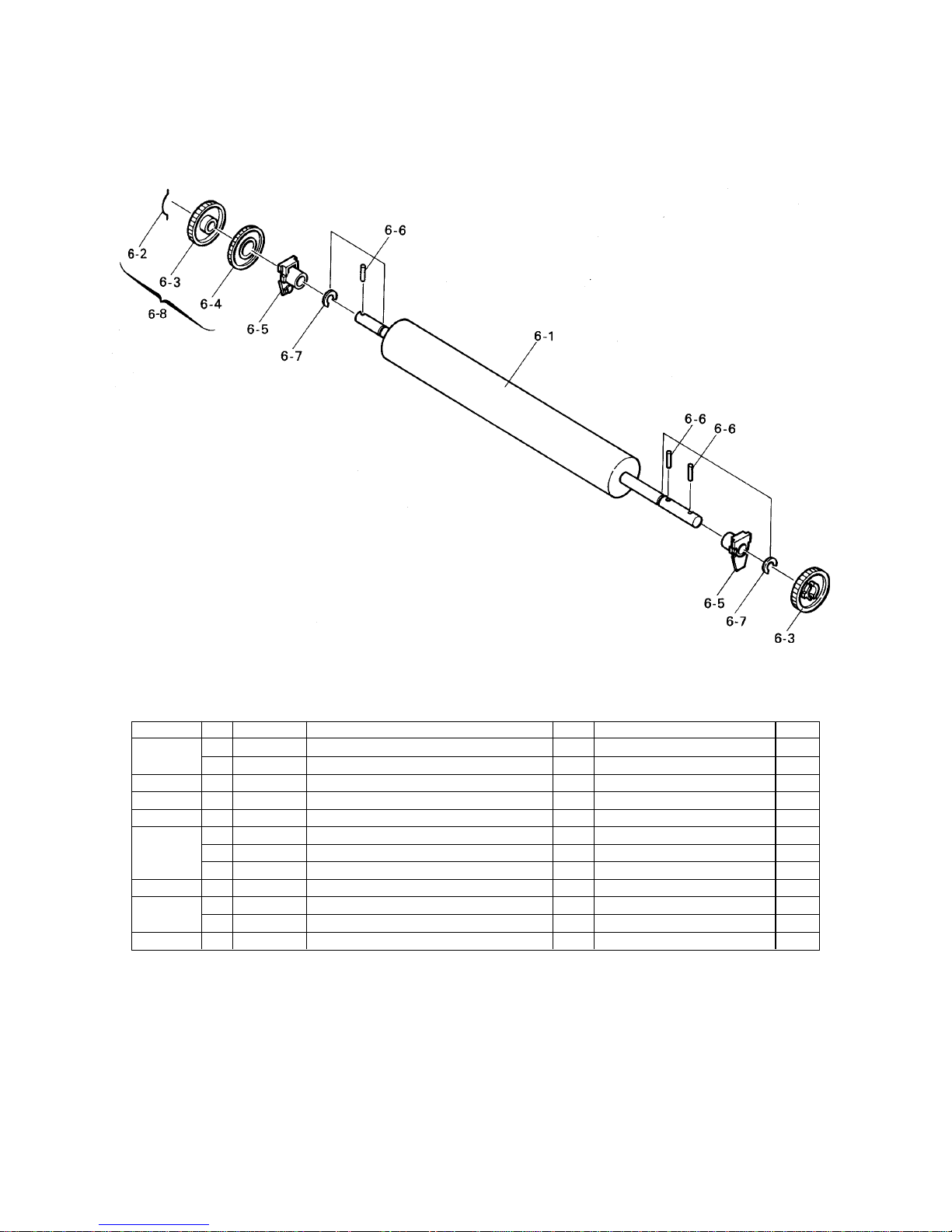
– 79 –
6-1 *7 80202030 PLATEN 891 1
#7 80202031 PLATEN 891 1
6-2 80530520 PLATEN GEAR SPRING 891 1 S
6-3 83100550 PLATEN GEAR A 891 2 S
6-4 83100560 PLATEN GEAR B 891 1 S
6-5 *2 83200660 PLATEN HOLDER 891 2 S
*4 83200661 PLATEN HOLDER 891 2 S
#4 83200662 PLATEN HOLDER 891 2 S
6-6 04012502 ROLL PIN SP2.5X12 3 S
6-7 *4 04020014 STOP RING SE6.0 2 S
#4 04020022 STOP RING SE6.0-SUS 2 S
6-8 #5 87063340 PLATEN GEAR ASSY 891B 1 WITH NO.6-2,3,4 S
3-5. Platen Unit
Platen Unit (Ver. 1 and 1.5)
DRWG.NO. REV. PARTS NO. PARTS NAME Q'TY REMARKS RANK
Page 83
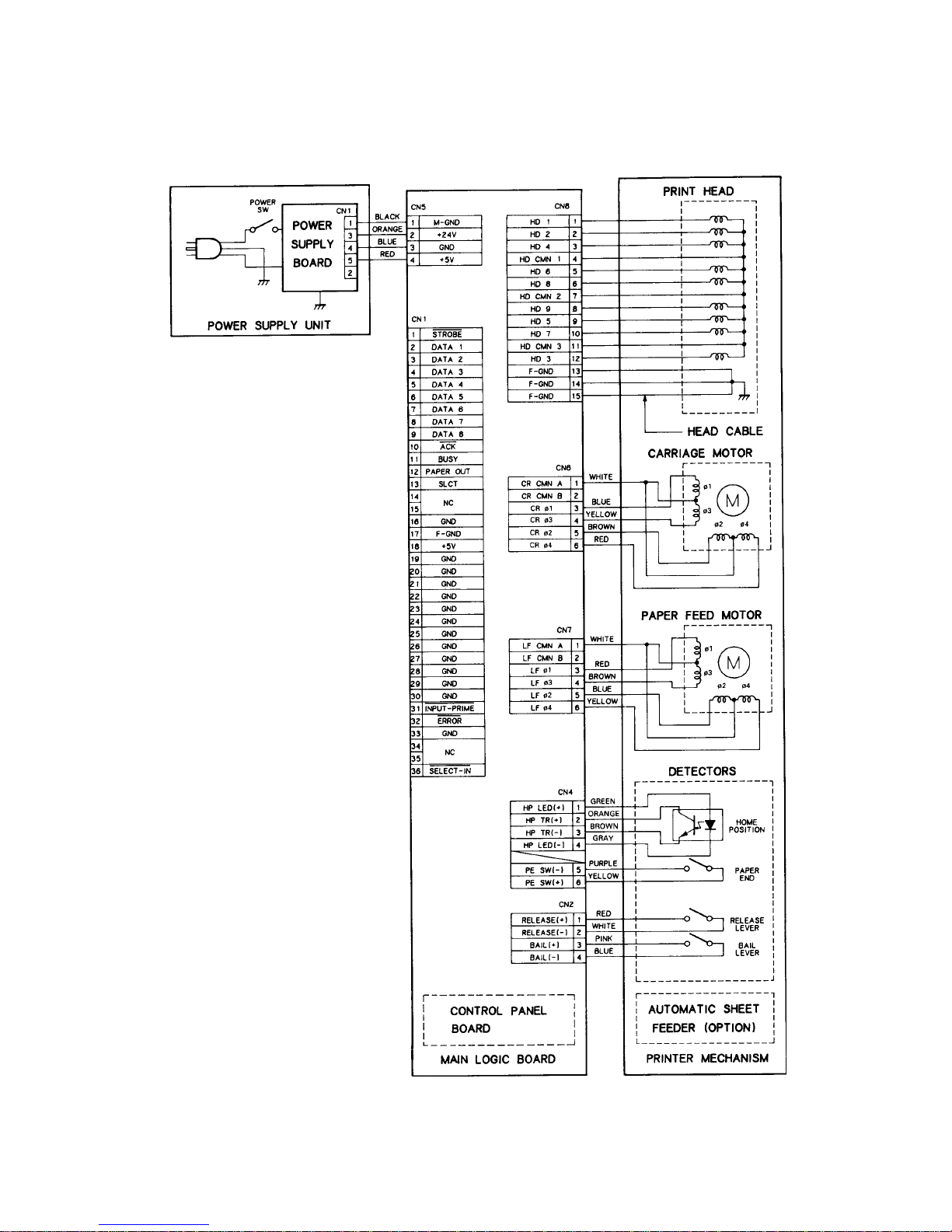
– 80 –
4. Wiring Scheme of Printer (Ver. 1 and 1.5)
4-1. Parallel Type
WIRING SCHEME
Page 84

– 81 –
4-2. Commodore Type
WIRING SCHEME
Page 85

– 82 –
5. Main Logic Board (Ver. 1 and 1.5)
5-1. Parallel Type (Ver. 1)
5-1-1. Component Layout
A. Board
Page 86
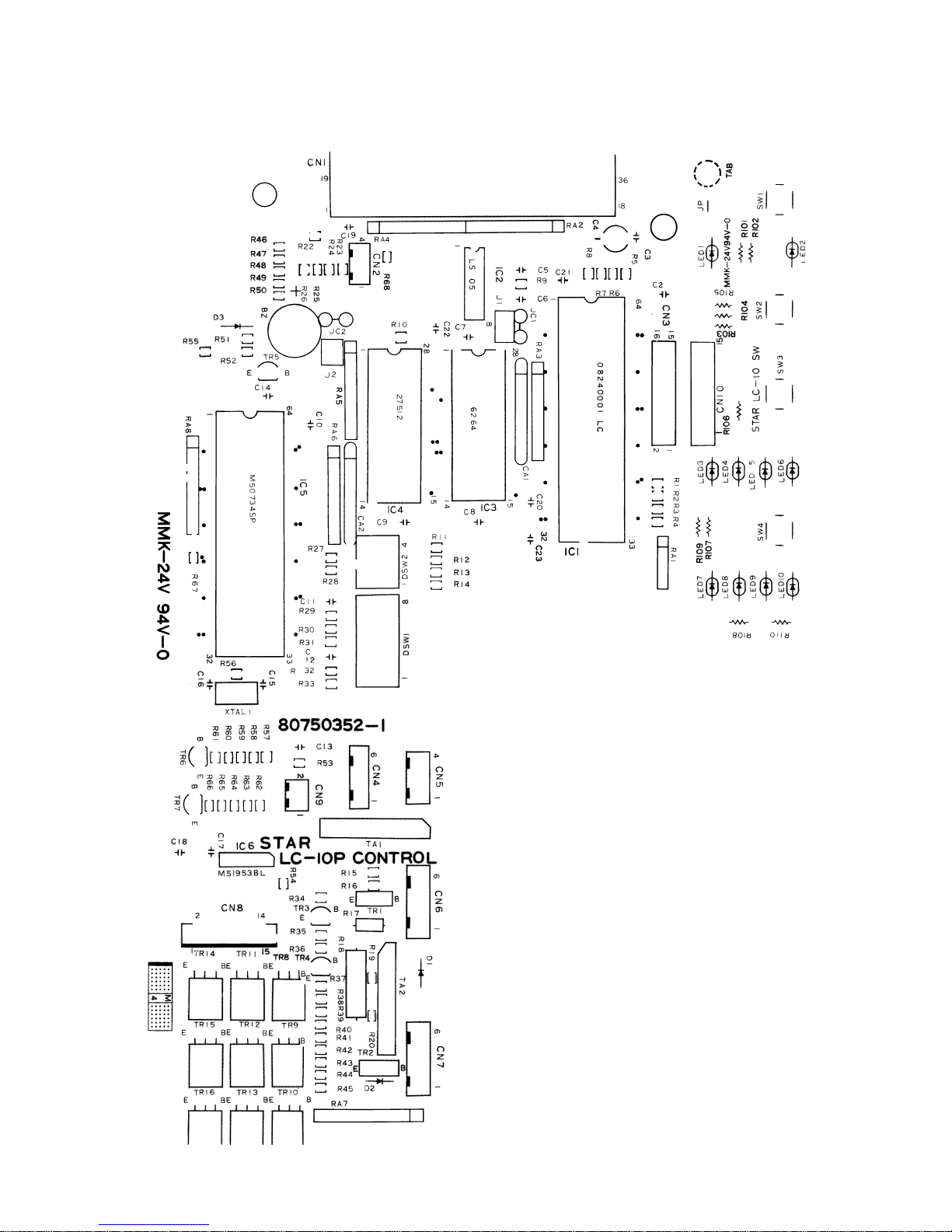
– 83 –
B. Board
Page 87

– 84 –
5-1-2. Parts List Main Logic Board (Parallel Type Ver.1)
Main Logic Board (Parallel Type Ver.1)
DRWG.NO. REV. PARTS NO. PARTS NAME Q'TY REMARKS RANK
IC1 08240001 GATE ARRAY D65006CW-LC 1 S
IC2 08210017 TTL IC 74LS05 1
IC3 08221002 SRAM HM6264P-100NS 1 FOR MONO S
#1 08221007 PSRAM HM65256BLP-100NS 1 FOR CL S
IC4 08220116 EPROM 27512-150NS 1 NX1P.1* :FOR MONO S
#1 08220116 EPROM 27512-150NS 1 NX1P.1*.CL :FOR CL S
#4 08220116 EPROM 27512-150NS 1 NX1P.1*.SUCL :FOR SU S
IC5 08250001 CPU M50734SP-10 1 S
IC6 08200109 IC-RESET M51953BL 1 S
TA1-2 07650029 TRANSISTOR ARRAY MP4001 2 S
TR1-2 07110121 TRANSISTOR 2SB1012K 2 S
TR3 07227853 TRANSISTOR 2SC1740SE 1
TR4 07011752 TRANSISTOR 2SA1266* 1
TR5-7 07227853 TRANSISTOR 2SC1740SE 3
TR8-16 07316371 TRANSISTOR 2SD1637 9 S
D1-2 08000044 DIODE 1SR139-100AT 2
D3 *8 08000039 DIODE 1S1588 1
#8 08000096 DIODE 1S2076A*A 1
RA1 *2 06584721 RESIS. ARRAY 4.7K-OHM 1/8W 4EL 1
#2 06584720 RESIS. ARRAY 4.7K-OHM 1/8W 4EL 1
RA2 *2 06584723 RESIS. ARRAY 4.7K-OHM 1/8W 8EL 1
#2 06584729 RESIS. ARRAY 4.7K-OHM 1/8W 8EL 1
RA3 NOT MOUNTED
RA4 *2 06584723 RESIS. ARRAY 4.7K-OHM 1/8W 8EL 1
#2 06584729 RESIS. ARRAY 4.7K-OHM 1/8W 8EL 1
RA5 *2 06581032 RESIS. ARRAY 10 K-OHM 1/8W 8EL 1
#2 06581038 RESIS. ARRAY 10 K-OHM 1/8W 8EL 1
RA6 NOT MOUNTED
RA7 *2 06581022 RESIS. ARRAY 1 K-OHM 1/8W 9EL 1
#2 06581028 RESIS. ARRAY 1 K-OHM 1/8W 9EL 1
RA8 *2 06584723 RESIS. ARRAY 4.7K-OHM 1/8W 8EL 1
#2 06584729 RESIS. ARRAY 4.7K-OHM 1/8W 8EL 1
R1-9 06054725 RD RESISTOR 4.7 K-OHM 1/6W 9
R10 NOT MOUNTED
R11 06054725 RD RESISTOR 4.7 K-OHM 1/6W 1
R12 06058224 RD RESISTOR 8.2 K-OHM 1/6W 1
R13 06054725 RD RESISTOR 4.7 K-OHM 1/6W 1
R14 06058224 RD RESISTOR 8.2 K-OHM 1/6W 1
R15-16 06051034 RD RESISTOR 10 K-OHM 1/6W 2
R17 06022206 RD RESISTOR 22 OHM 1/2W 1
R18 *2 06200271 RN RESISTOR 2.7 OHM 2W 2% 1
#2 06200274 RN RESISTOR 2.7 OHM 2W 2% 1
R19-20 06051034 RD RESISTOR 10 K-OHM 1/6W 2
R21 NOT USED
R22 NOT MOUNTED
R23-31 06054725 RD RESISTOR 4.7 K-OHM 1/6W 9
R32 06054734 RD RESISTOR 47 K-OHM 1/6W 1
R33 06051514 RD RESISTOR 150 OHM 1/6W 1
R34 06051034 RD RESISTOR 10 K-OHM 1/6W 1
R35 06052224 RD RESISTOR 2.2 K-OHM 1/6W 1
R36 06051034 RD RESISTOR 10 K-OHM 1/6W 1
R37-45 06053314 RD RESISTOR 330 OHM 1/6W 9
R46-49 06054725 RD RESISTOR 4.7 K-OHM 1/6W 4
R50 06051014 RD RESISTOR 100 OHM 1/6W 1
R51 06051514 RD RESISTOR 150 OHM 1/6W 1
R52 06051034 RD RESISTOR 10 K-OHM 1/6W 1
Page 88

– 85 –
Main Logic Board (Parallel Type Ver.1)
DRWG.NO. REV. PARTS NO. PARTS NAME Q'TY REMARKS RANK
R53 NOT MOUNTED
R54 06051525 RD RESISTOR 1.5 K-OHM 1/6W 1
R55 06054725 RD RESISTOR 4.7 K-OHM 1/6W 1
R56 06051051 RD RESISTOR 1 M-OHM 1/6W 1
R57-60 06051025 RD RESISTOR 1 K-OHM 1/6W 4
R61 06051034 RD RESISTOR 10 K-OHM 1/6W 1
R62-65 06051025 RD RESISTOR 1 K-OHM 1/6W 4
R66 06051034 RD RESISTOR 10 K-OHM 1/6W 1
R67 06054725 RD RESISTOR 4.7 K-OHM 1/6W 1
R68 *2 06041521 RD RESISTOR 1.5 K-OHM 1/4W 1
#2 06051525 RD RESISTOR 1.5 K-OHM 1/6W 1
R101-110 06052714 RD RESISTOR 270 OHM 1/6W 10
CA1 05654711 CAPA. ARRAY 470PF 50V 8EL 1 FOR MONO
#2 05653311 CAPA. ARRAY 330PF 50V 8EL 1 FOR CL
CA2 05651012 CAPA. ARRAY 100PF 50V 8EL 1
C1 NOT USED
C2 05152234 CERA. CAPA. 0.022UF 50V 1
C3 NOT MOUNTED
C4 05051062 CHEM. CAPA. 10UF 50V 1
C5 05154714 CERA. CAPA. 470PF 50V 1
C6 05154714 CERA. CAPA. 470PF 50V 1 FOR MONO
#2 05151015 CERA. CAPA. 100PF 50V 1 FOR CL
C7 05152234 CERA. CAPA. 0.022UF 50V 1
C8 NOT MOUNTED
C9 05152234 CERA. CAPA. 0.022UF 50V 1
C10 05154723 CERA. CAPA. 4700PF 50V 1
C11 NOT MOUNTED
C12 05154714 CERA. CAPA. 470PF 50V 1
C13 NOT MOUNTED
C14 05152234 CERA. CAPA. 0.022UF 50V 1
C15-16 05153303 CERA. CAPA. 33PF 50V 2
C17 05152234 CERA. CAPA. 0.022UF 50V 1
C18 *2 05131042 CERA. CAPA. 0.1UF 25V 1
#2 05551044 CAPACITOR 0.1UF 50V 1
C19-20 05152234 CERA. CAPA. 0.022UF 50V 2
C21 05152212 CERA. CAPA. 220PF 50V 1
C22 05152234 CERA. CAPA. 0.022UF 50V 1
C23 #2 05152212 CERA. CAPA. 220PF 50V 1 FOR CL ONLY
C24 #2 05151013 CERA. CAPA. 100PF 50V 1 FOR CL ONLY
XTAL1 09250032 CERA. OSCILLATOR KBR10MHZ 1
BZ 45060201 QMB-111P 1
DSW1 *2 09090018 DIP SWITCH KSD08 1
#2 09090034 DIP SWITCH KSS08-1 1
DSW2 *2 09090016 DIP SWITCH KSD04 1
#2 09090033 DIP SWITCH KSS04-1 1
SW1-4 *2 09010041 PUSH SWITCH SKHHAL 4
#2 09010043 PUSH SWITCH SKHHAL=S 4
LED1 08300055 LED LT-1H11A 1
LED2-9 08300058 LED LT-1E21A 8
LED10 08300055 LED LT-1H11A 1
JC1 #1 NOT MOUNTED:FOR MONO
#1 93930006 JUMPER WIRE STP122 1 :FOR CL
JC2 NOT MOUNTED
CN1 09100155 CONNECTOR 57L-40360-770B-D147 1
CN2 *4 09100342 CONNECTOR 53014-0410 1
*6 09100476 CONNECTOR 53014-0470 1
Page 89

– 86 –
CN2 #6 09100342 CONNECTOR 53014-0410 1
CN3 09100339 CONNECTOR FC-16 1
CN4 *4 09100341 CONNECTOR 53014-0610 1
*6 09100474 CONNECTOR 53014-0670 1
#6 09100341 CONNECTOR 53014-0610 1
CN5 09100317 CONNECTOR 5483-04A 1
CN6 09100267 CONNECTOR 5483-06A 1
CN7 09100278 CONNECTOR 5483-06A-RED 1
CN8 *2 09100340 CONNECTOR HLEM15S-1 1
#2 09100384 CONNECTOR HLEM15S-2 1
CN9 NOT MOUNTED
CN10 09100339 CONNECTOR FC-16 1
- 80700250 WIRE 18UL1007BLK055T 1
Main Logic Board (Parallel Type Ver.1)
DRWG.NO. REV. PARTS NO. PARTS NAME Q'TY REMARKS RANK
Page 90

– 87 –
[ Blank Page]
Page 91

– 88 –
5-1-3. Circuit Diagram (Ver.1)
Page 92
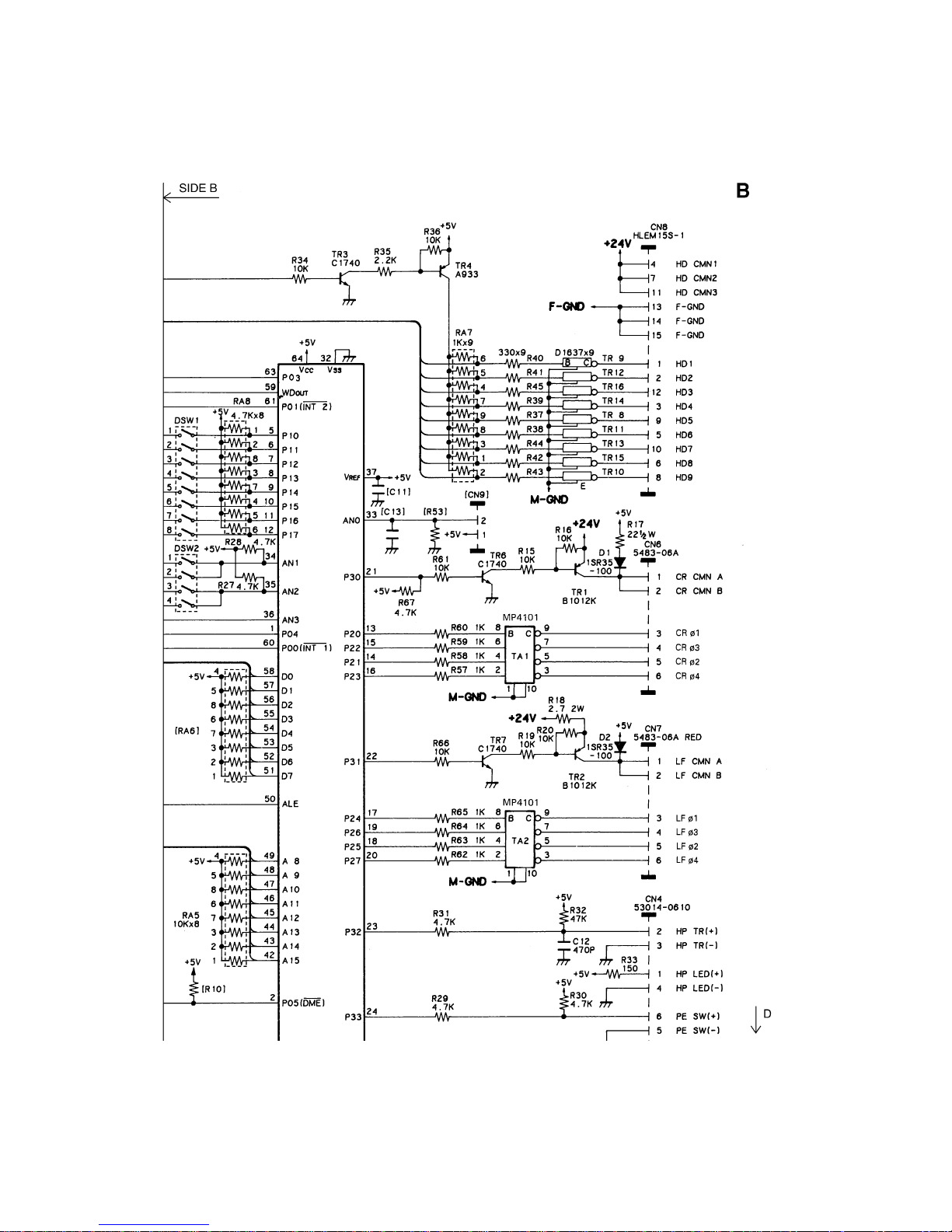
– 89 –
Page 93

– 90 –
Page 94

– 91 –
Page 95

– 92 –
5-2. Parallel Type (Ver.1.5)
5-2-1. Component Layout (A Board)
Page 96

– 93 –
5-2-1. Component Layout (B Board)
Page 97

– 94 –
5-2-2. Parts List
Main Logic Board (Parallel Type Ver.1.5)
DRWG.NO. REV. PARTS NO. PARTS NAME Q'TY REMARKS RANK
IC1 08250001 CPU M50734SP-10 1 S
IC2 08220116 EPROM 27512-150NS 1 NX1P.2* :FOR MONO S
08220116 EPROM 27512-150NS 1 NX1P.2*.CL :FOR CL S
IC3 08221002 SRAM HM6264P-100NS 1 S
IC4 08240013 GATE ARRAY D65006CW-LC2 1 S
IC5 08210017 TTL IC 74LS05 1
IC6 08200109 IC-RESET M51953BL 1 S
TA201-202 *4 07650031 TRANSISTOR ARRAY STA401A 2 S
#4 07650040 TRANSISTOR ARRAY MP4101 2 S
TR1 07011752 TRANSISTOR 2SA1266* 1
TR2-5 07227853 TRANSISTOR 2SC1740SE 4
TR6-14 07320101 TRANSISTOR 2SD2010 9 S
TR201-202 07113591 TRANSISTOR 2SB1359 2 S
D1 *8 08000039 DIODE 1S1588 1
#8 08000096 DIODE 1S2076A*A 1
D201-202 08000044 DIODE 1SR139-100AT 2
D203 #2 93930006 JUMPER WIRE STP122 1
RA1 06584720 RESIS. ARRAY 4.7K-OHM 1/8W 4EL 1
RA2 *3 06584728 RESIS. ARRAY 4.7K-OHM 1/8W 6EL 1
*4 06581824 RESIS. ARRAY 1.8K-OHM 1/8W 6EL 1
#4 06581823 RESIS. ARRAY 1.8K-OHM 1/8W 6EL 1
RA3 06584729 RESIS. ARRAY 4.7K-OHM 1/8W 8EL 1
RA4 NOT MOUNTED
RA5 06581028 RESIS. ARRAY 1 K-OHM 1/8W 9EL 1
RA6 06584720 RESIS. ARRAY 4.7K-OHM 1/8W 4EL 1
RA7 06584729 RESIS. ARRAY 4.7K-OHM 1/8W 8EL 1
R1 06051525 RD RESISTOR 1.5 K-OHM 1/6W 1
R2-10 06054725 RD RESISTOR 4.7 K-OHM 1/6W 9
R11 *3 06054725 RD RESISTOR 4.7 K-OHM 1/6W 1
#3 06051025 RD RESISTOR 1 K-OHM 1/6W 1
R12 06051014 RD RESISTOR 100 OHM 1/6W 1
R13 06054725 RD RESISTOR 4.7 K-OHM 1/6W 1
R14 *3 06054725 RD RESISTOR 4.7 K-OHM 1/6W 1
#3 06051025 RD RESISTOR 1 K-OHM 1/6W 1
R15 06051034 RD RESISTOR 10 K-OHM 1/6W 1
R16 06051514 RD RESISTOR 150 OHM 1/6W 1
R17-19 06054725 RD RESISTOR 4.7 K-OHM 1/6W 3
R20 06051034 RD RESISTOR 10 K-OHM 1/6W 1
R21 06052224 RD RESISTOR 2.2 K-OHM 1/6W 1
R22 06051034 RD RESISTOR 10 K-OHM 1/6W 1
R23 06051051 RD RESISTOR 1 M-OHM 1/6W 1
R24-25 06051034 RD RESISTOR 10 K-OHM 1/6W 2
R26-34 06053314 RD RESISTOR 330 OHM 1/6W 9
R35 06054725 RD RESISTOR 4.7 K-OHM 1/6W 1
R36 06054734 RD RESISTOR 47 K-OHM 1/6W 1
R37 06051514 RD RESISTOR 150 OHM 1/6W 1
R38 NOT MOUNTED
R39-42 06054725 RD RESISTOR 4.7 K-OHM 1/6W 4
R43-44 #2 NOT MOUNTED
R45 06058224 RD RESISTOR 8.2 K-OHM 1/6W 1
R46-50 06054725 RD RESISTOR 4.7 K-OHM 1/6W 5
R101-110 06052714 RD RESISTOR 270 OHM 1/6W 10
R201 06200274 RN RESISTOR 2.7 OHM 2W 2% 1
R202 06022206 RD RESISTOR 22 OHM 1/2W 1
R203-204 06051034 RD RESISTOR 10 K-OHM 1/6W 2
R205-208 06051025 RD RESISTOR 1 K-OHM 1/6W 4
Page 98

– 95 –
Main Logic Board (Parallel Type Ver.1.5)
DRWG.NO. REV. PARTS NO. PARTS NAME Q'TY REMARKS RANK
R209-210 06051034 RD RESISTOR 10 K-OHM 1/6W 2
R211-214 06051025 RD RESISTOR 1 K-OHM 1/6W 4
CA1 05652212 CAPA. ARRAY 220PF 50V 8EL 1
CA2-4 05651012 CAPA. ARRAY 100PF 50V 8EL 3
C1 05152234 CERA. CAPA. 0.022UF 50V 1
C2 NOT MOUNTED :FOR HK
05254732 FILM CAPA. 0.047UF 50V 1 EXCEPT FOR HK
C3-4 NOT USED
C5 05532234 CAPACITOR 0.022UF 25V 1
C6 05551044 CAPACITOR 0.1UF 50V 1
C7 05152234 CERA. CAPA. 0.022UF 50V 1
C8 05552214 CAPACITOR 220PF 50V 1
C9 *4 05154714 CERA. CAPA. 470PF 50V 1
#4 05554714 CAPACITOR 470PF 50V 1
C10 05532234 CAPACITOR 0.022UF 25V 1
C11 05554714 CAPACITOR 470PF 50V 1
C12 *4 05154723 CERA. CAPA. 4700PF 50V 1
#4 05524724 CAPACITOR 4700PF 16V 1
C13 NOT MOUNTED
C14 05532234 CAPACITOR 0.022UF 25V 1
C15-16 05152212 CERA. CAPA. 220PF 50V 2
C17-19 05532234 CAPACITOR 0.022UF 25V 3
C20 05552214 CAPACITOR 220PF 50V 1
C21 NOT MOUNTED :FOR HK
05254732 FILM CAPA. 0.047UF 50V 1 EXCEPT FOR HK
C22 05554714 CAPACITOR 470PF 50V 1
C23 05154714 CERA. CAPA. 470PF 50V 1
XTAL1 09250035 CERA. OSCILLATOR CST10.0MT 1
BZ1 45060201 QMB-111P 1
DSW1 09090034 DIP SWITCH KSS08-1 1
DSW2 09090033 DIP SWITCH KSS04-1 1
SW1-4 09010043 PUSH SWITCH SKHHAL=S 4
LED1 08300055 LED LT-1H11A 1
LED2-9 08300058 LED LT-1E21A 8
LED10 08300055 LED LT-1H11A 1
JC1 80700250 WIRE 18UL1007BLK055T 1
JC101 80924670 WIRE 20UL1015BLK100 1
JC201 80924670 WIRE 20UL1015BLK100 1
CN1 09100155 CONNECTOR 57L-40360-770B-D147 1
CN2 *4 09100342 CONNECTOR 53014-0410 1
*6 09100476 CONNECTOR 53014-0470 1
#6 09100342 CONNECTOR 53014-0410 1
CN3 09100339 CONNECTOR FC-16 1
CN4 *4 09100341 CONNECTOR 53014-0610 1
*6 09100474 CONNECTOR 53014-0670 1
#6 09100341 CONNECTOR 53014-0610 1
CN5 09100317 CONNECTOR 5483-04A 1
CN6 09100404 CONNECTOR 5483-06A-BLK 1
CN7 09100278 CONNECTOR 5483-06A-RED 1
CN8 09100384 CONNECTOR HLEM15S-2 1
CN9-11 09100339 CONNECTOR FC-16 3
J1 93930006 JUMPER WIRE STP122 1
J2 NOT MOUNTED
J3-49 93930006 JUMPER WIRE STP122 47
J50 NOT MOUNTED
J51-77 93930006 JUMPER WIRE STP122 27
Page 99

– 96 –
J78 NOT MOUNTED
J79-85 93930006 JUMPER WIRE STP122 7
J101-103 93930006 JUMPER WIRE STP122 3
J201-204 93930006 JUMPER WIRE STP122 4
- #4 80702221 CABLE UNIT 16X150 2 FOR CN3-10,CN9-11
*6 80086510 BOARD ID SEAL HK 1 ONLY HK
Main Logic Board (Parallel Type Ver.1.5)
DRWG.NO. REV. PARTS NO. PARTS NAME Q'TY REMARKS RANK
Page 100

– 97 –
[Blank Page]
 Loading...