

Page 1
LC-IO
COLOUR PRINTER
USERS MANUAL
NOT INTENDED FOR SALE
PN 8082025 I
Page 2
Federal Communications Commission
Radio Frequency Interference Statement
This equipment generates and uses radio frequency energy and if not installed and used properly,
that is, in strict accordance with the manufacturer’s instructions, may cause interference. to radio
and television reception. It has been type tested and found to comply with the limits for a Class
B computing device in accordance with the specifications in Subpart J of Part 15 of FCC Rules,
which are designed to provide reasonable protection against such interference in a residential
installation. However, there is no guarantee that interference will not occur in a particular
installation. If this equipment does cause interference to radio or television reception, which
can be determined by turning the equipment off and on, the user is encouraged to try to correct
the interference by otle or more of the following measures:
l Reorient the receiving antenna
l Relocate the computer or printer with respect to the receiver
l Move the computer or printer away from the receiver
l Plug the computer or printer into a different outlet so that it and the receiver are on
different branch circuits.
If necessary, the user should consult the dealer or an experienced redio/television technician
for additional suggestions. The user may find the following booklet, prepared by the Federal
Communications-Commission helpful: “How to Identify and Resolve Radio-TV Interference
Problems.” This booklet is available from the U.S. Government Printing Office, Washington,
DC., 20402, Stock No. 004-000-00345-4.
For compliance with the Federal Noise Interference Standard, this equipment requires a shielded
cable.
The above statement applies only to printers marketed in the U.S.A.
Self Declaration
Radio interference regarding this equipment has been eliminated according to Vfg 1046/1984
announced by the DBP.
DBP has been informed of the introduction of this special equipment and has been granted the
right to examine the whole series.
It is the user’s responsibility to see that his own assembled system is in accordance with the
technical regulations under Vfg 1046/1984.
To conform to FTZ-regulations it is necessary to make all connections to the printer with shielded
cable.
The equipment may only be opened by qualified service representatives.
The above statement applies only to printers marketed in West Germany.
Trademark Acknowledgements
LC-10, NL.40, NP-10, NX-10/15, ND-lo/H, M-10/15: Star Micronics Co., Ltd.
IBM PC, IBM Proprinter II, PC-DOS: International Business Machines Corp.
Microsoft BASIC, MSDOS: Microsoft Corporation
LX-800, FX-%e, EX400, LX&l/W Seiko Epson Corp.
NOTICE
l All rights reserved. Reproduction of any part of this manual in any form whatsoever
without STAR’s express permission is forbidden.
l The contents of this manual are subject to change without notice.
l All efforts have been made to ensure the accuracy of the contents of this manual at the
time of press. However, should any errors be detected, STAR would greatly appreciate
being informed of them.
l The above notwithstanding, STAR can assume no responsibility for any errors in this
manual.
--
@Copyright 1987 Star Micronics Co., Ltd.
Page 3
HOW TO USE THIS MANUAL
This manual is organized into five chapters and four appendixes. To
learn how to make the best use of your printer you are urged to read all
of chapters 1 through 5. The appendixes can be referred to as necessary.
Chapter 1 explains how to get the printer unpacked and set up. Read this
chapter before you do anything else.
Chapter 2 explains the control panel. After getting set up, read this chapter
and try out the procedures in it to find out how the printer works.
Chapter 3 gives tips on using word-processing programs and other commercial software with this printer. Read this chapter in conjunction with
your software manual.
Chapter 4 is addressed to do-it-yourself programmers. It shows simple
programming examples using DOS commands and BASIC.
Chapter 5 covers maintenance and troubleshooting. Look through this
chapter to see what it contains, then refer to it as necessary later.
Appendix A lists the printer’s technical specifications.
Appendix B details the functions of escape sequences and other printer
commands.
Appendix C presents a BASIC program you can use to define and download
new characters.
Appendix D presents tables of the printer’s character sets.
Page 4
FEATURES OF THE PRINTER
This printer is a compact, colour, dot-matrix printer that supports the
IBM/Epson commands and character sets. An excellent partner for your
personal computer, it prints text and graphics in black-and-white or six bright
colours. A print sample generated by a BASIC program is included inside
the back cover. With more advanced software, you can produce even more
striking colour graphics. Besides colour printing, some of the features of
this printer are:
l Extensive software support
Since it is compatible with the Epson and IBM printers, it works with
any software that supports those printers. That includes most word-processing and graphics programs, spreadsheets, and integrated software
packages.
l Embeddable commands
Commands for NLQ type styles, colour printing, bold, italic, and extra-large characters can be embedded in documents without the escape code,
so you can use these features easily even if your word-processing software
does not support them.
l Easy operation
Clearly understandable lamp displays and beep tones provide immediate
feedback when you press the switches on the control panel. The four switches
can operate in combinations to perform a surprising variety of functions,
including margen setting and micro-alignment.
l Easy care and maintenance
The colour ribbon cartridge can be replaced in seconds; the print head
in a few minutes.
l Versatile paper handling
Single sheets, fanfold forms, and multi-copy forms (up to triple-ply)
are ail accepted, and you can use either tractor or friction feed. A speical
feature enables you to keep fanfold forms parked in readiness while printing
on other paper.
l Fast draht-quality printing
At 120 characters per second, the printer can print a page faster than
you can read it. Characters are naturally shaped, with true descenders.
l High-resolution near-letter-quality printing
When you select an NLQ type style, the printer slows down and employs
a dense matrix of up to 18 by 23 dots to print clear, well-formed characters.
l Large variety of type styles and sizes
The printer has one draht style and four NLQ styles (Courier, Sanserif,
and Orator with small capitals or lower case), plus italics for all styles, plus
condensed print, bold print, double-sized print, quadruple-sized print-see
the print sample inside the back cover.
Page 5
TABLE OF CONTENTS
Chapter 1
Chapter 2
SETTING UP THE PRINTER
Locating the printer
Unpacking and inspection
Check the carton contents
Setting up
Mount the platen knob
Remove the top cover
Install the ribbon cartridge
Replace the top cover
Connect the printer to the computer
Connect the printer’s power cord
Loading single sheets
Mount the paper guide
Semiautomatic loading
Manual loading
Loading and parking fanfold forms
Paper parking
Paper unparking
Test printing
Short self test
Long selft test
Interface test
Adjusting the printing gap
DIP switch settings
CONTROL PANEL OPERATIONS
Switches and indicators
Power indicator
On Line switch
Paper Feed switch
Print Pitch switch
NLQ Type Style switch
Power-up functions
Short test pattern
Long test pattern
Stay in panel pitch
Stay in panel style
Hexadecimal dump
Switch combination functions
Paper parking
Page feed
1
1
1
3
6
9
12
14
14
19
19
23
26
Page 6
Top of form
Forward micro-feed
Reverse micro-feed
Left margin
Right margin
Clearing the buffer
Chapter 3
USING THE PRINTER WITH
COMMERCIAL SOFTWARE
Installing your software
Printer menu
Printer command options
Type styles
Page width
Initialization sequence
Setting the DIP switches
Using your software
Page alignment
Type style and pitch selection
Embedding printer commands
Chapter 4
USING THE PRINTER
WITH DOS AND BASIC
Hard-copying the screen (MS DOS and PC-DOS)
Programming the printer with DOS commands
Programming the printer with BASIC
Chapter 5
MAINTENANCE AND TROUBLESHOOTING A7
Cleaning the printer
Replacing the ribbon
Replacing the print head
Troubleshooting
Appendix A TECHNICAL SPECIFICATIONS
Appendix B PRINTER CONTROL COMMANDS
Font control commands
Colour printing commands
Character set commands
Character size and pitch commands
Vertical position commands
Horizontal position commands
Graphics commands
Download character commands
Macro instruction commands
Other printer control commands
31
31
33
33
37
37
38
40
47
47
48
50
53 59
59
64
64
66
71
76
80
82
85
85
Page 7
I
Appendix C DOWNLOAD CHARACTER GENERATOR 89
Draft character
NLQ character
Appendix D CHARACTER SETS
Standard character set
IBM character set #2
IBM character set #l
Additional character set
International character sets
INDEX
REFERENCE CARD
Inside the cover
97
98
100
102
103
104
105
Page 8
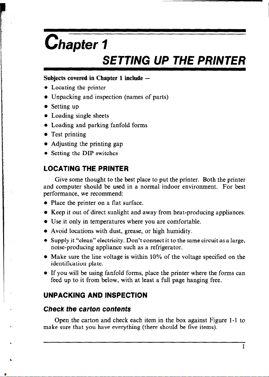
SETTING UP THE PRINTER
E
Subjects covered in Chapter 1 include -
l Locating the printer
l Unpacking and inspection (names of parts)
0 Setting up
l Loading single sheets
l Loading and parking fanfold forms
l Test printing
l Adjusting the printing gap
l Setting the DIP switches
LOCATING THE PRINTER
Give some thought to the best place to put the printer. Both the printer
and computer should be used in a normal indoor environment. For best
performance, we recommend:
l Place the printer on a flat surface.
l Keep it out of direct sunlight and away from heat-producing appliances.
l Use it only in temperatures where you are comfortable.
l Avoid locations with dust, grease, or high humidity.
l Supply it “clean” electricity. Don’t connect it to the same circuit as a large,
noise-producing appliance such as a refrigerator.
l Make sure the line voltage is within 10% of the voltage specified on the
identification plate.
l If you will be using fanfold forms, place the printer where the forms can
feed up to it from below, with at least a full page hanging free.
UNPACKING AND INSPECTION
Check the carton contents
Open the carton and check each item in the box against Figure l-1 to
make sure that you have everything (there should be five items).
L
.
Page 9
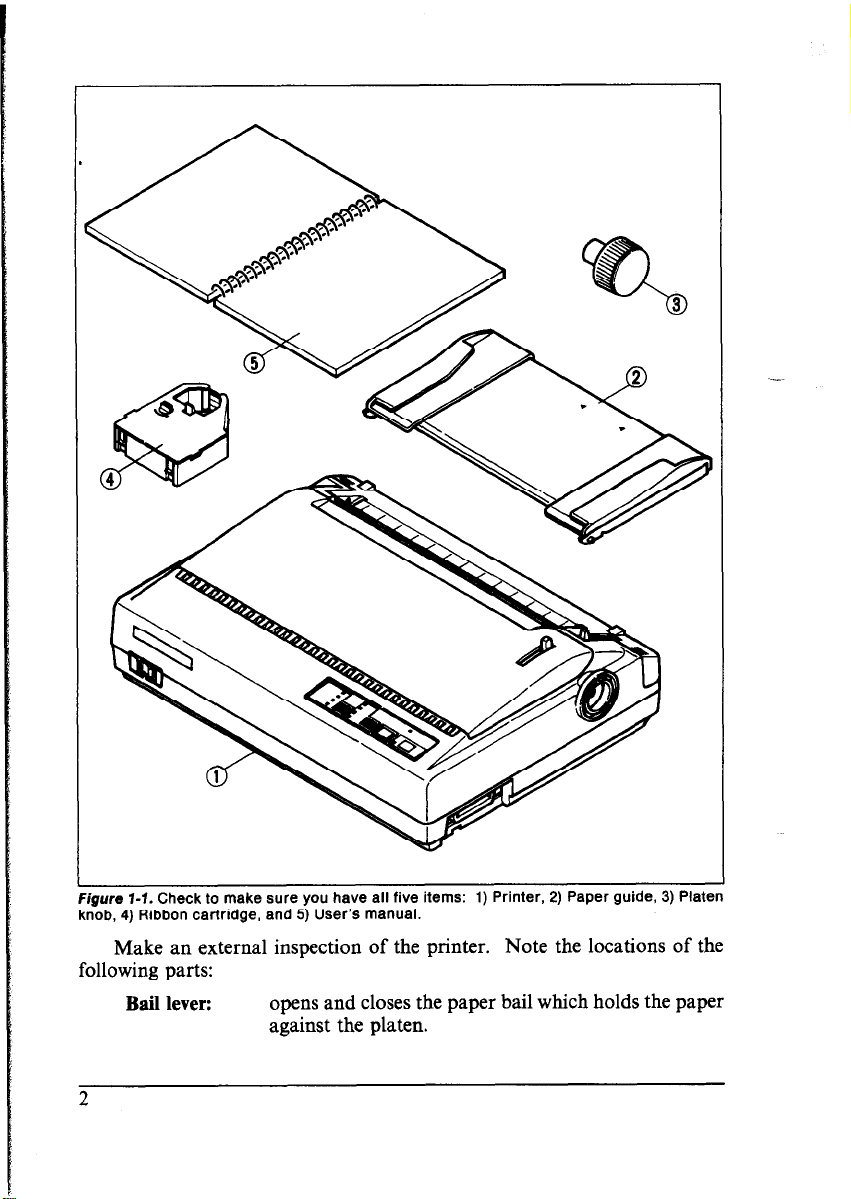
Figure 1-f. Check to make sure you have all five items: 1) Printer, 2) Paper guide, 3) Platen
knob, 4) Ribbon cartridge, and 5) User’s manual.
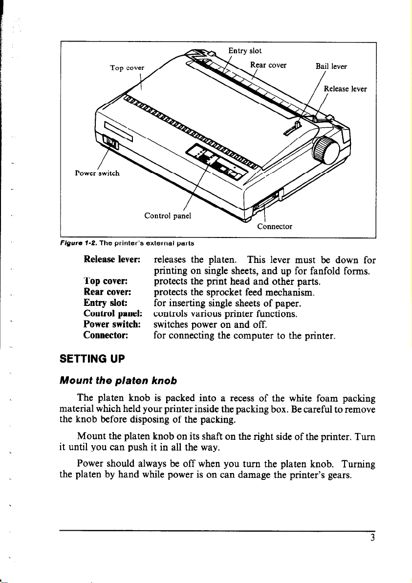
Make an external inspection of the printer. Note the locations of the
following parts:
Bail lever:
opens and closes the paper bail which holds the paper
against the platen.
2
Page 10
Bail lever
Poa
Release lever: releases the platen. This lever must be down for
printing on single sheets, and up for fanfold forms.
Top cover:
Rear cover:
protects the print head and other parts.
protects the sprocket feed mechanism.
Entry slot: for inserting single sheets of paper.
Control panel: controls various printer functions.
Power switch: switches power on and off.
Connector:
for connecting the computer to the printer.
SETTING UP
Mount the platen knob
The platen knob is packed into a recess of the white foam packing
material which held your printer inside the packing box. Be careful to remove
the knob before disposing of the packing.
Mount the platen knob on its shaft on the right side of the printer. Turn
it until you can push it in all the way.
Power should always be off when you turn the platen knob. Turning
the platen by hand while power is on can damage the printer’s gears.
3
Page 11
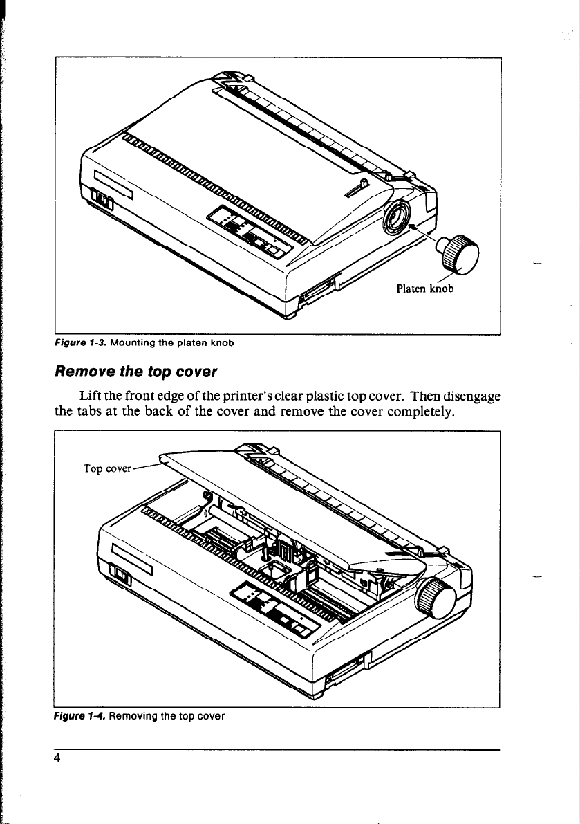
Remove the top cower
Lift the front edge of the printer’s clear plastic top cover. Then disengage
the tabs at the back of the cover and remove the cover completely.
-
-
igure 1-4. Removing the top cover
Page 12
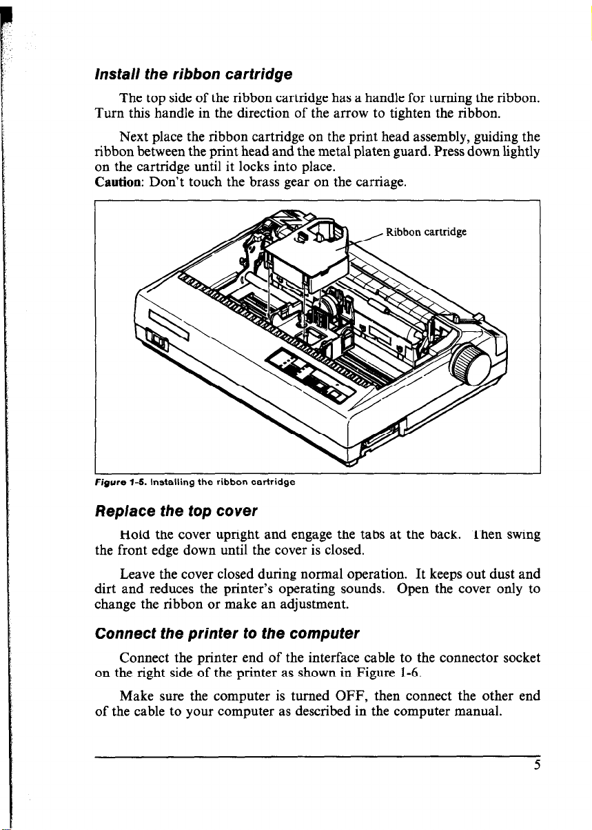
hstall the ribbon cartridge
The top side of the ribbon cartridge has a handle for turning the ribbon.
Turn this handle in the direction of the arrow to tighten the ribbon.
Next place the ribbon cartridge on the print head assembly, guiding the
ribbon between the print head and the metal platen guard. Press down lightly
on the cartridge until it locks into place.
Caution: Don’t touch the brass gear on the carriage.
I
Figure l-5. Installing the ribbon cartridge
Replace the top cover
Hold the cover upright and engage the tabs at the back. Then swing
the front edge down until the cover is closed.
Leave the cover closed during normal operation. It keeps out dust and
dirt and reduces the printer’s operating sounds. Open the cover only to
change the ribbon or make an adjustment.
Connect the printer to the computer
Connect the printer end of the interface cable to the connector socket
on the right side of the printer as shown in Figure 1-6.
Make sure the computer is turned OFF, then connect the other end
of the cable to your computer as described in the computer manual.
Page 13
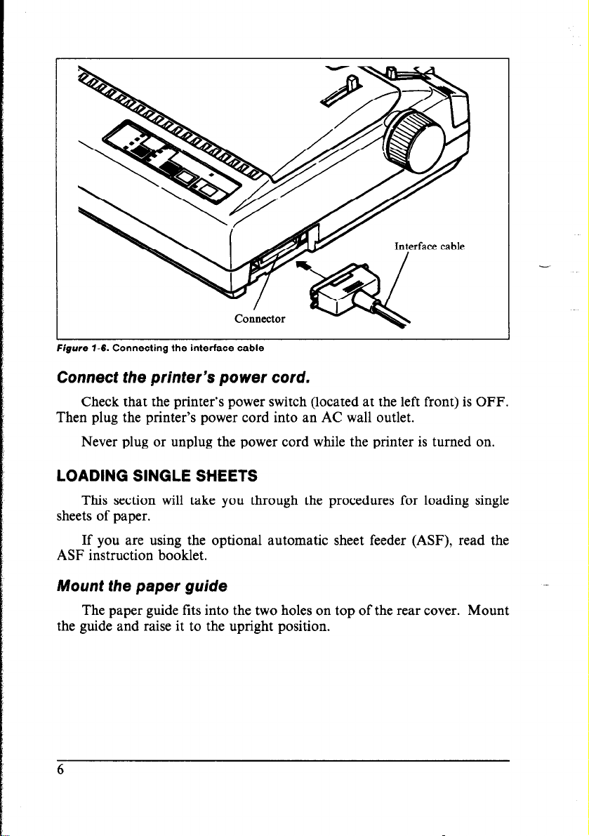
Figure l-6. r;onnectmg tne mtertace caue
Connect the printer’s power cord.
Check that the printer’s power switch (located at the left front) is OFF.
Then plug the printer’s power cord into an AC wall outlet.
Never plug or unplug the power cord while the printer is turned on.
LOADING SINGLE SHEETS
This section will take you through the procedures for loading single
sheets of paper.
If you are using the optional automatic sheet feeder (ASF), read the
ASF instruction booklet.
Mount the paper guide
The paper guide fits into the two holes on top of the rear cover. Mount
the guide and raise it to the upright position.
6
Page 14
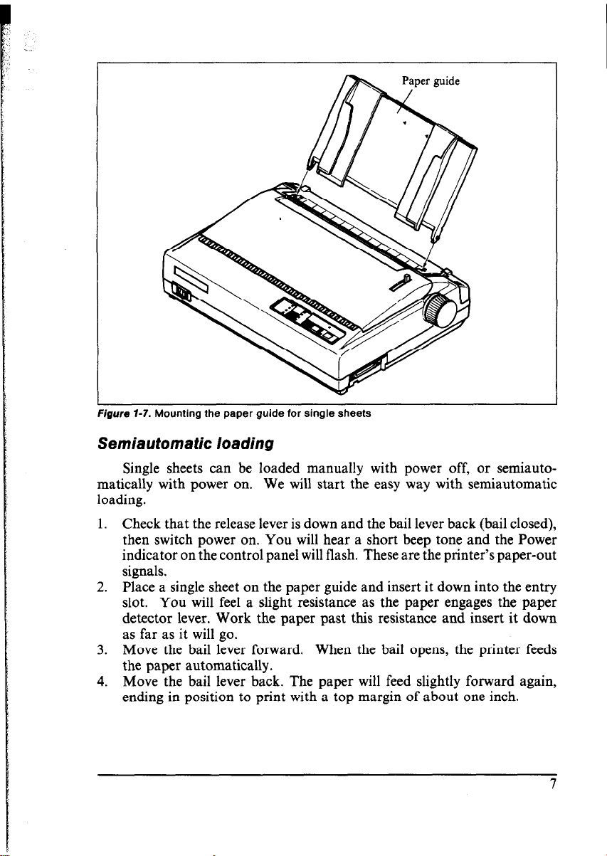
igure i-7. Mounting the paper guide for single sheets
Semiautomatic loading
Single sheets can be manually with off, or
matically with on. We start the way with
loading.
1. that the lever is and the lever back closed),
then power on. will hear short beep and the
indicator on control panel flash. These are the printer’s paper-out
signals.
Place a sheet on paper guide insert it into the
slot. You feel a resistance as paper engages paper
detector Work the past this and insert down
as as it go.
3. the bail forward. When bail opens, printer feeds
paper automatically.
Move the lever back. paper will slightly forward
ending in to print a top of about inch.
Page 15
lever
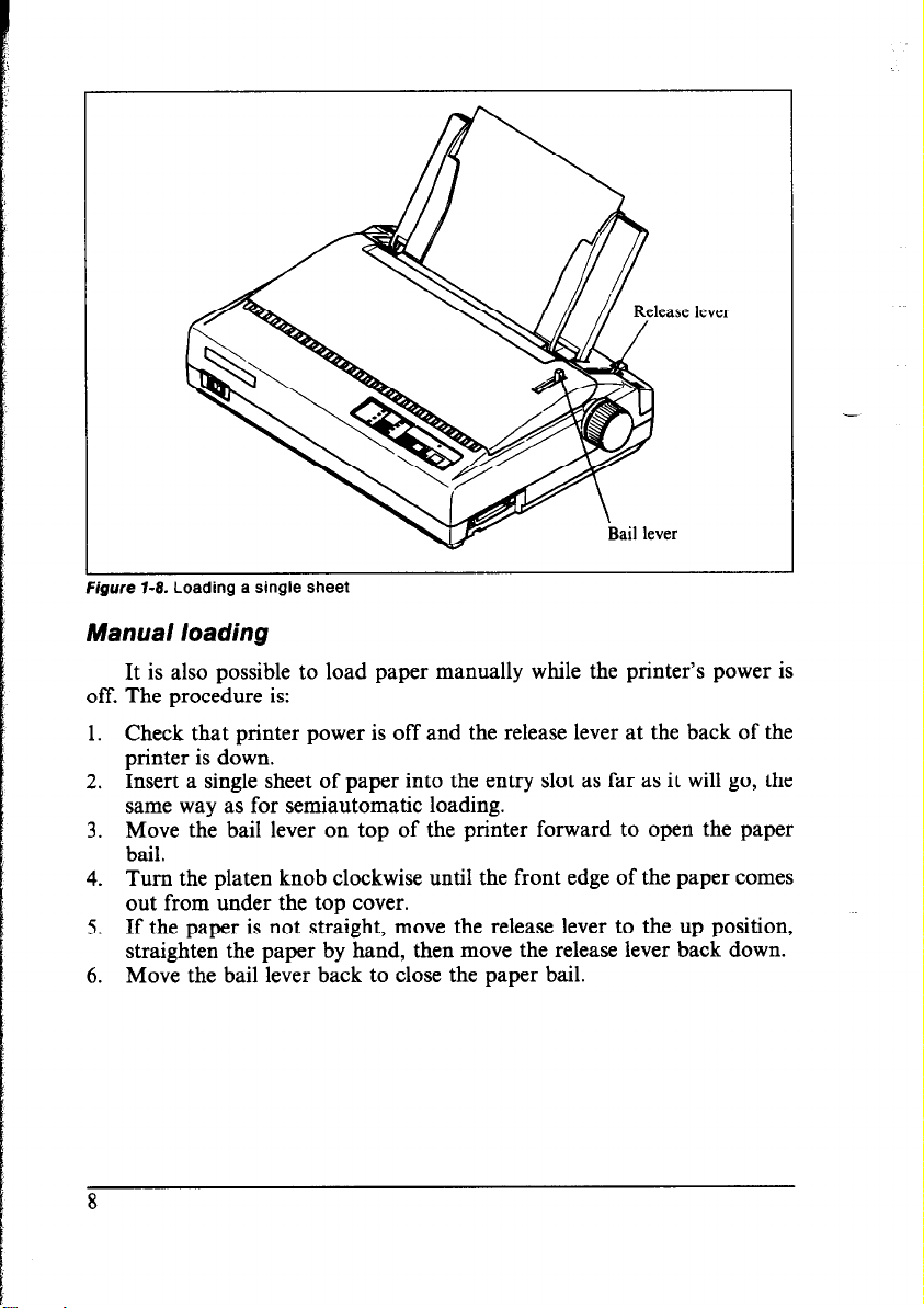
Manual loading
It is also possible to load paper manually while the printer’s power is
off. The procedure is:
1. Check that printer power is off and the release lever at the back of the
printer is down.
2. Insert a single sheet of paper into the entry slot as far as it will go, the
same way as for semiautomatic loading.
3. Move the bail lever on top of the printer forward to open the paper
bail.
4. Turn the platen knob clockwise until the front edge of the paper comes
out from under the top cover.
5. If the paper is not straight, move the release lever to the up position,
straighten the paper by hand, then move the release lever back down.
6. Move the bail lever back to close the paper bail.
8
Page 16
LOADING AND PARKING FANFOLD FORMS
Fanfold forms have holes along the sides and perforations between the
sheets. They are also called sprocket forms, punched forms, or just plain
“computer paper”. This printer accepts forms up to 10” wide. Fanfold forms
are loaded, parked, and unparked as explained next.
1. Place a stack of fanfold paper behind and at least one page-length below
the printer.
2. Turn the printer’s power OFF.
3. Set the release lever to the up position. If there is paper in the printer,
remove it. (Since the platen is released, you can just pull the paper out.)
4. Move the bail lever forward to open the bail.
5. Remove the paper guide and put it aside for the moment.
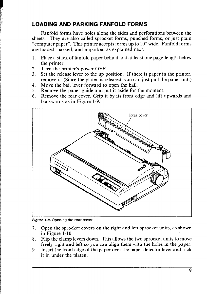
6. Remove the rear cover. Grip it by its front edge and lift upwards and
backwards as in Figure l-9.
Figure 7-9. Opening the rear cover
7. Open the sprocket covers on the right and left sprocket units, as shown
in Figure l-10.
8. Flip the clamp levers down. This allows the two sprocket units to move
freely right and left so you can align them with the holes in the paper.
9. Insert the front edge of the paper over the paper detector lever and tuck
it in under the platen.
9
Page 17
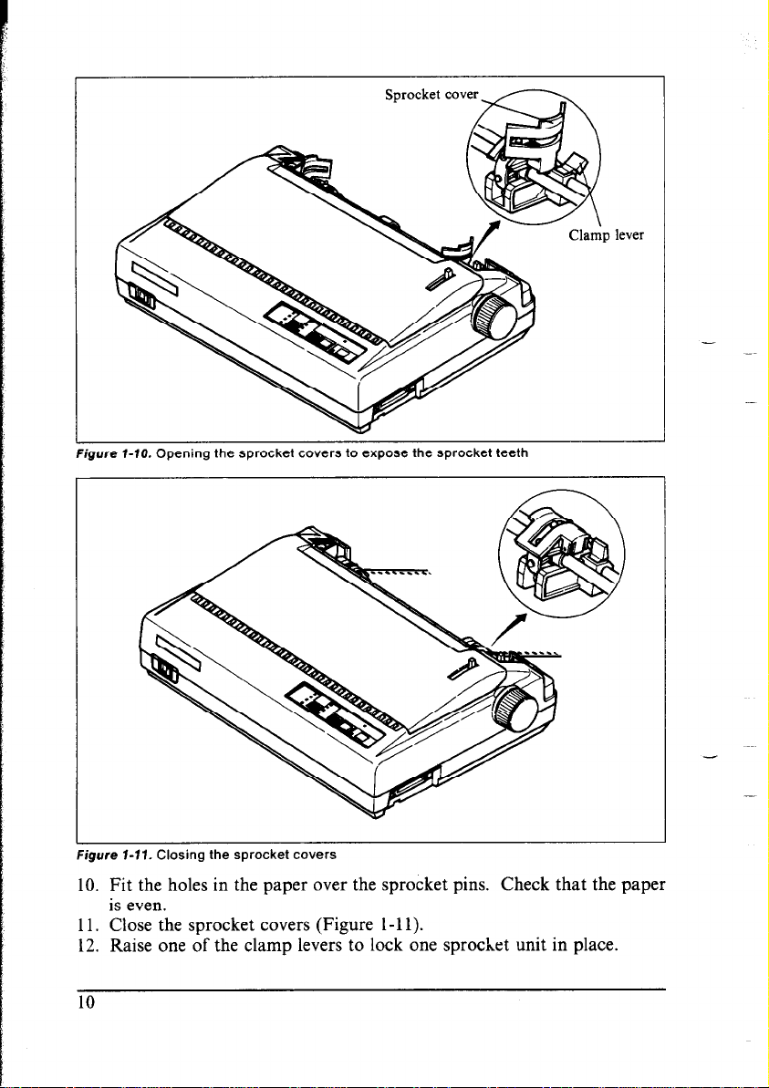
Figure l-10. Opening the sprocket covers to expose the sprocket teeth
lever
-
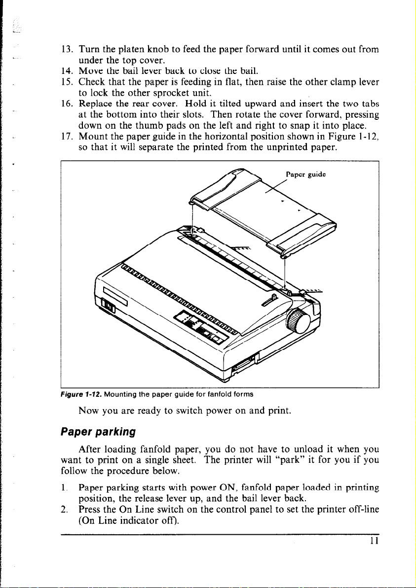
igure l-71. Closing the sprocket covers
10. Fit the holes in the paper over the sprocket pins. Check that the paper
is even.
11. Close the sprocket covers (Figure l-l 1).
12. Raise one of the clamp levers to lock one sprocket unit in place.
Page 18
13. Turn the platen knob to feed the paper forward until it comes out from
under the top cover.
14. Move the bail lever back to close the bail.
15. Check that the paper is feeding in flat, then raise the other clamp lever
to lock the other sprocket unit.
16. Replace the rear cover. Hold it tilted upward and insert the two tabs
at the bottom into their slots. Then rotate the cover forward, pressing
down on the thumb pads on the left and right to snap it into place.
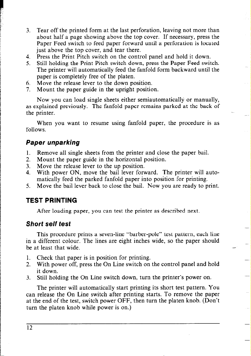
17. Mount the paper guide in the horizontal position shown in Figure 1-12,
so that it will separate the printed from the unprinted paper.
‘gure 1-12. Mounting the paper guide for fanfold forms
Now you are ready to switch power on and print.
Paper parking
After loading fanfold paper, you do not have to unload it when you
want to print on a single sheet. The printer will “park” it for you if you
follow the procedure below.
1. Paper parking starts with power ON, fanfold paper loaded in printing
position, the release lever up, and the bail lever back.
2. Press the On Line switch on the control panel to set the printer off-line
(On Line indicator off).
11
Page 19
3. Tear off the printed form at the last perforation, leaving not more than
about half a page showing above the top cover. If necessary, press the
Paper Feed switch to feed paper forward until a perforation is located
just above the top cover, and tear there.
4. Press the Print Pitch switch on the control panel and hold it down.
5. Still holding the Print Pitch switch down, press the Paper Feed switch.
The printer will automatically feed the fanfold form backward until the
paper is completely free of the platen.
6. Move the release lever to the down position.
7. Mount the paper guide in the upright position.
Now you can load single sheets either semiautomatically or manually,
as explained previously. The fanfold paper remains parked at the back of
the printer.
When you want to resume using fanfold paper, the procedure is as
follows.
Paper unparking
1. Remove all single sheets from the printer and close the paper bail.
2. Mount the paper guide in the horizontal position.
3. Move the release lever to the up position.
4. With power ON, move the bail lever forward. The printer will auto-
matically feed the parked fanfold paper into position for printing.
5. Move the bail lever back to close the bail. Now you are ready to print.
TEST PRINTING
After loading paper, you can test the printer as described next.
Short self test
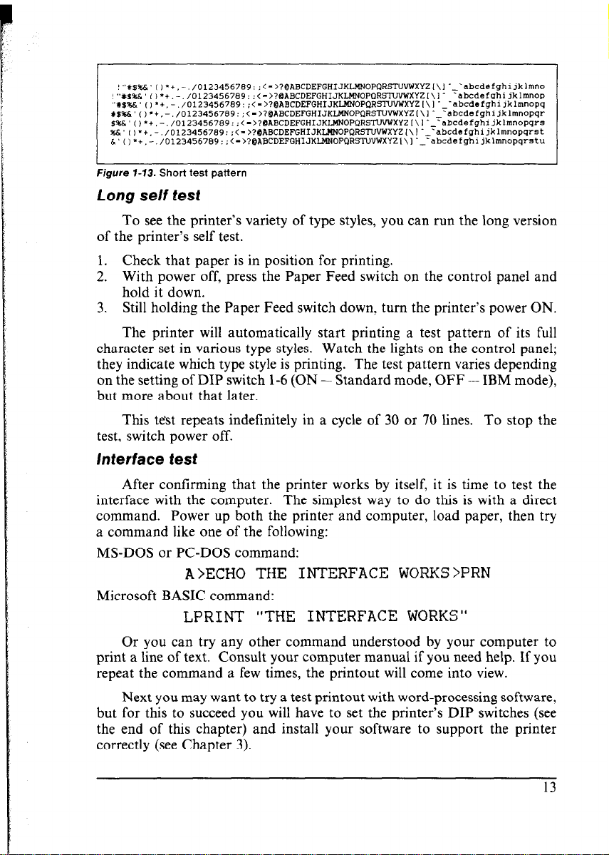
This procedure prints a seven-line “barber-pole” test pattern, each line
in a different colour. The lines are eight inches wide, so the paper should
be at least that wide.
1. Check that paper is in position for printing.
2. With power off, press the On Line switch on the control panel and hold
it down.
3. Still holding the On Line switch down, turn the printer’s power on.
The printer will automatically start printing its short test pattern. You
can release the On Line switch after printing starts. To remove the paper
at the end of the test, switch power OFF, then turn the platen knob. (Don’t
turn the platen knob while power is on.)
12
-
-
Page 20
I
Figure 7-13. Short test pattern
Long se/f test
To see the printer’s variety of type styles, you can run the long version
of the printer’s self test.
1. Check that paper is in position for printing.
2. With power off, press the Paper Feed switch on the control panel and
hold it down.
3. Still holding the Paper Feed switch down, turn the printer’s power ON.
The printer will automatically start printing a test pattern of its full
character set in various type styles. Watch the lights on the control panel;
they indicate which type style is printing. The test pattern varies depending
on the setting of DIP switch l-6 (ON - Standard mode, OFF - IBM mode),
but more about that later.
This test repeats indefinitely in a cycle of 30 or 70 lines. To stop the
test, switch power off.
interface test
After confirming that the printer works by itself, it is time to test the
interface with the computer. The simplest way to do this is with a direct
command. Power up both the printer and computer, load paper, then try
a command like one of the following:
MS-DOS or PC-DOS command:
A>ECHO THE INTERFACE WORKS >PRN
Microsoft BASIC command:
LPRINT “THE INTERFACE WORKS“
Or you can try any other command understood by your computer to
print a line of text. Consult your computer manual if you need help. If you
repeat the command a few times, the printout will come into view.
Next you may want to try a test printout with word-processing software,
but for this to succeed you will have to set the printer’s DIP switches (see
the end of this chapter) and install your software to support the printer
correctly (see Chapter 3).
Page 21
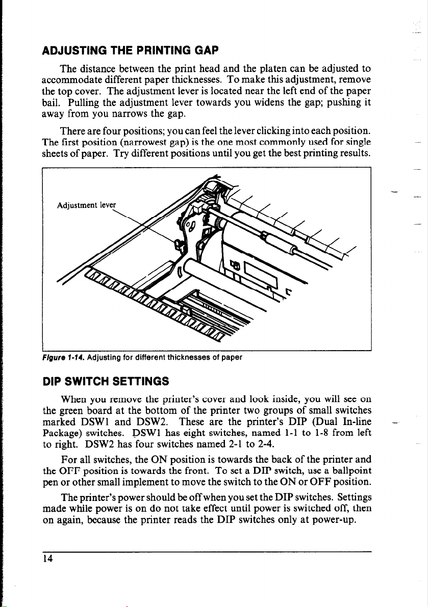
ADJUSTING THE PRINTING GAP
The distance between the print head and the platen can be adjusted to
accommodate different paper thicknesses. To make this adjustment, remove
the top cover. The adjustment lever is located near the left end of the paper
bail. Pulling the adjustment lever towards you widens the gap; pushing it
away from you narrows the gap.
There are four positions; you can feel the lever clicking into each position.
The first position (narrowest gap) is the one most commonly used for single
sheets of paper. Try different positions until you get the best printing results.
Adjustment lever
Figure 7-74. Adjusting for different thicknesses of paper
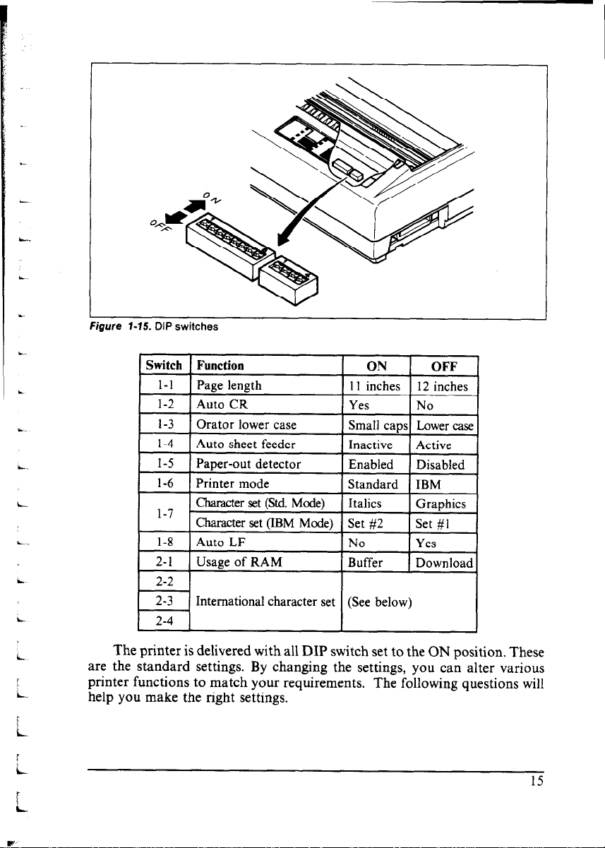
DIP SWITCH SETTINGS
When you remove the printer’s cover and look inside, you will see on
the green board at the bottom of the printer two groups of small switches
marked DSWl and DSW2. These are the printer’s DIP (Dual In-line
Package) switches. DSWl has eight switches, named l-l to 1-8 from left
to right. DSW2 has four switches named 2-l to 2-4.
For all switches, the ON position is towards the back of the printer and
the OFF position is towards the front. To set a DIP switch, use a ballpoint
pen or other small implement to move the switch to the ON or OFF position.
The printer’s power should be off when you set the DIP switches. Settings
made while power is on do not take effect until power is switched off, then
on again, because the printer reads the DIP switches only at power-up.
14
-
Page 22
I
I
Figure l-15. DIP switches
L
2-3
International character set (See below)
L
L
The printer is delivered with all DIP switch set to the ON position. These
are the standard settings. By changing the settings, you can alter various
2-4
printer functions to match your requirements. The following questions will
i..
6
i
I
L
t
help you make the right settings.
I5
Page 23
Switch l-l: Is the page length of your paper 11 inches or 12 inches?
Leave this switch ON if you will be using 11-inch forms. Move it to the
OFF position if you will be using 12-inch forms.
Switch 1-2:
Leave this switch ON. The printer will automatically perform a carriage
return by moving to the left margin at each line feed. Even if your software
sends a separate carriage-return code, an extra carriage return does no harm
because two consecutive carriage returns are the same as one. Very few
programs require this switch to be OFF.
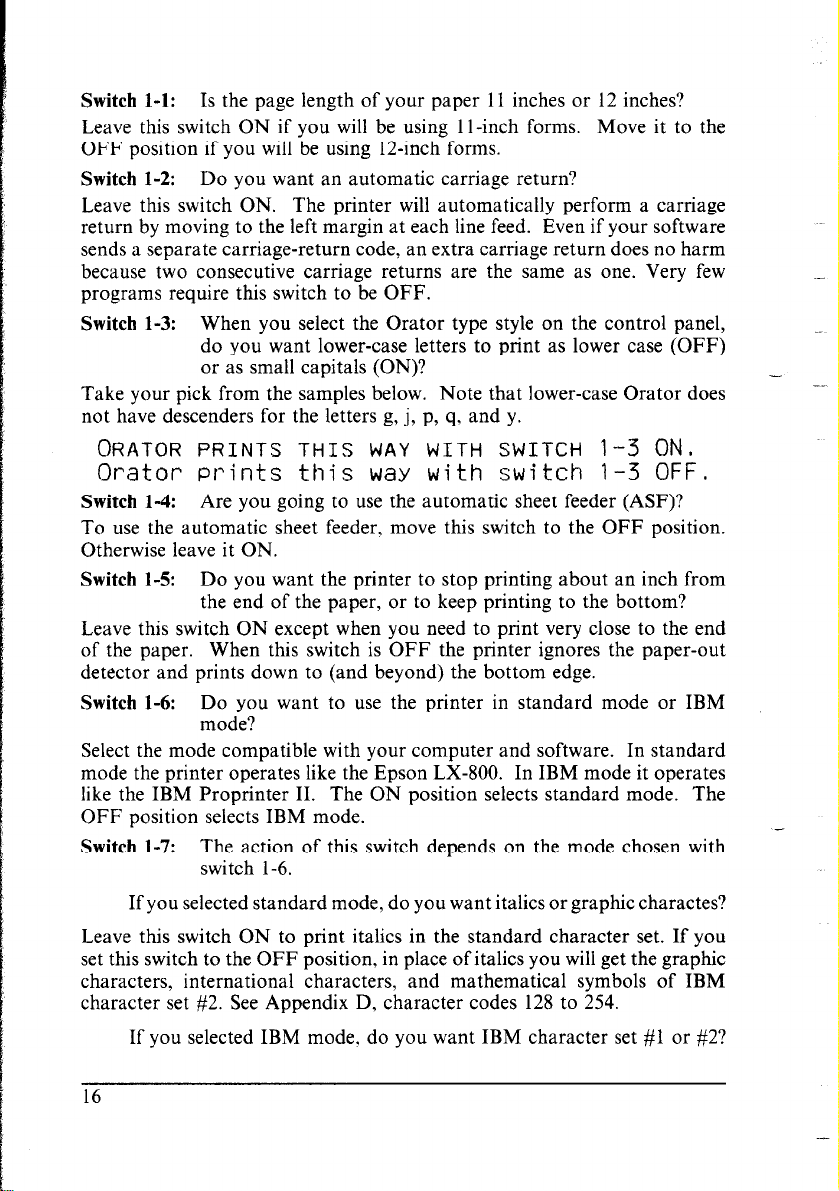
Switch 1-3: When you select the Orator type style on the control panel,
Take your pick from the samples below. Note that lower-case Orator does
not have descenders for the letters g, j, p, q. and y.
ORATOR PRINTS THIS WAY WITH SWITCH l-3 ON.
Do you want an automatic carriage return?
do you want lower-case letters to print as lower case (OFF)
or as small capitals (ON)?
Orator Prints this way with switch t-3 OFF.
Switch 1-4: Are you going to use the automatic sheet feeder (ASF)?
To use the automatic sheet feeder, move this switch to the OFF position.
Otherwise leave it ON.
Switch 1-5: Do you want the printer to stop printing about an inch from
the end of the paper, or to keep printing to the bottom?
Leave this switch ON except when you need to print very close to the end
of the paper. When this switch is OFF the printer ignores the paper-out
detector and prints down to (and beyond) the bottom edge.
Switch 1-6:
Select the mode compatible with your computer and software. In standard
mode the printer operates like the Epson LX-800. In IBM mode it operates
like the IBM Proprinter II. The ON position selects standard mode. The
OFF position selects IBM mode.
Switch l-7: The action of this switch depends on the mode chosen with
Do you want to use the printer in standard mode or IBM
mode?
switch l-6.
.-
-
-.
If you selected standard mode, do you want italics or graphic charactes?
Leave this switch ON to print italics in the standard character set. If you
set this switch to the OFF position, in place of italics you will get the graphic
characters, international characters, and mathematical symbols of IBM
character set #2. See Appendix D, character codes 128 to 254.
If you selected IBM mode, do you want IBM character set #l or #2?
16
Page 24
ON selects character set #2, which is for computers with an g-bit interface
(the most common kind). OFF selects character set #l, for computers with
a 7-bit interface.
Switch 1-8:
Do you want an automatic line feed?
If you leave this switch at the ON position, a separate line-feed code is required to obtain a line feed.
If you move this switch to the OFF position, the printer performs both a
carriage return and line feed each time it receives a carriage-return code.
Most computer systems send a line feed code, or both a carriage return and
line feed, at the end of each line, so this switch should be left ON.
If you get double line spacing when you expect single spacing, or if lines
overprint each other, try changing the setting of this switch.
Switch 2-1: Does your software download new characters to the printer?
To download characters this switch must be OFF. The printer then uses
its RAM memory for storing character patterns and provides only a one-line
print buffer. If you leave this switch ON the printer uses its RAM memory
as an input buffer, allowing the computer to send data faster than the printer
prints.
Switches 2-2 to 2-4:
Do you want an international character set?
International character sets differ in their assignment of 14 character codes.
See the character tables at the back of this manual. With the DIP switches
you can select one of eight character sets as follows:
* Denmark/Norway when switch 1-6 is OFF and switch l-7 is ON.
Page 25
MEMO
Page 26
Chapter 2
CONTROL PANEL OPERAT/O/VS
This chapter explains how to use the control panel to:
0 Pause printing
l Feed paper (fast and slow, forward and reverse)
l Select the print pitch
0 Select a type style
0 Print test patterns
l Prevent software from changing the panel pitch and style selections
l Print a hexadecimal dump
l Park fanfold forms
l Set the top-of-form position
l Set the left and right margins
l Clear the printer’s buffer
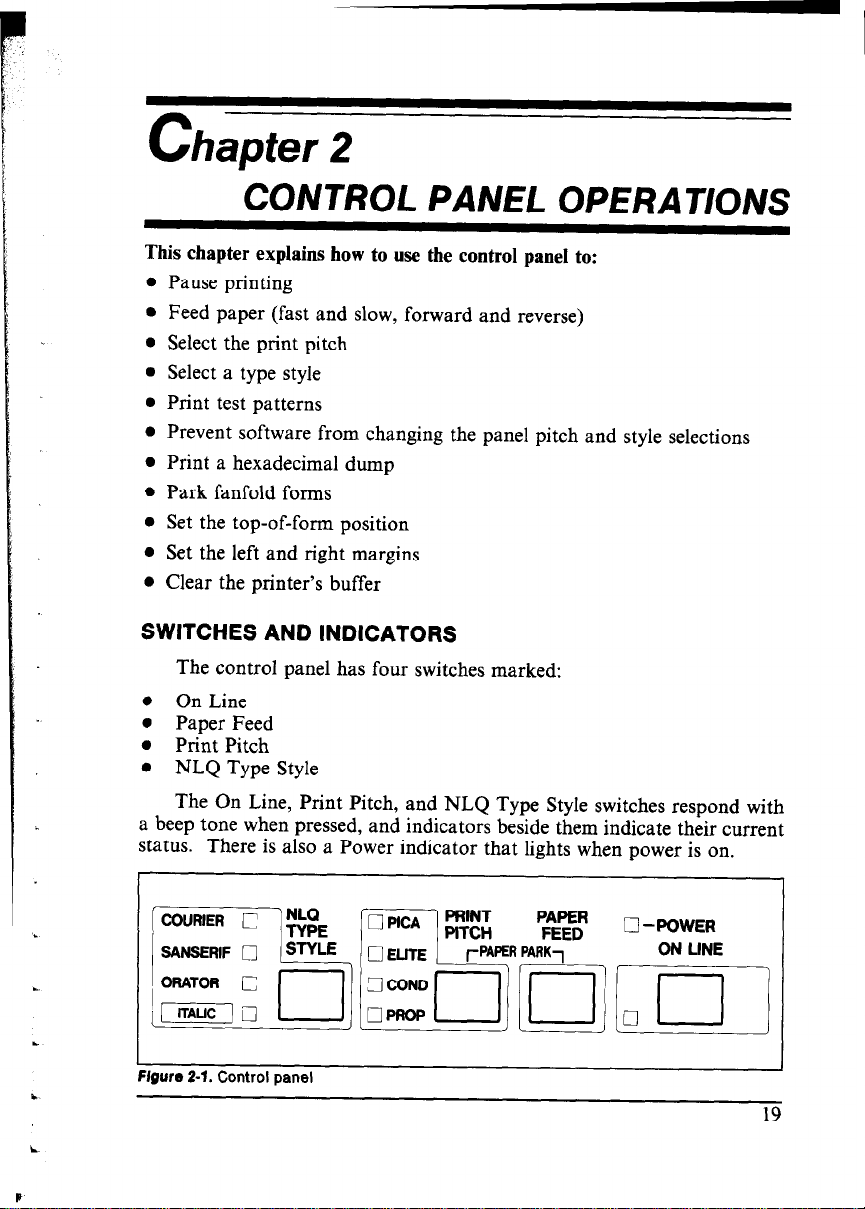
SWITCHES AND INDICATORS
The control panel has four switches marked:
0 On Line
l Paper Feed
l Print Pitch
l NLQ Type Style
The On Line, Print Pitch, and NLQ Type Style switches respond with
a beep tone when pressed, and indicators beside them indicate their current
status. There is also a Power indicator that lights when power is on.
.
c
Figure 2-f. Control panel
q -POWER
ON LINE
Page 27
The control panel switches can be pressed singly to perform the operations indicated by their names. Other functions can be obtained by holding
these switches down when you turn the printer’s power on. Still further
functions can be executed by pressing the control panel switches in combination. This chapter explains all the switch and indicator functions.
Power indicator
The power indicator lights (yellow) when power is on.
When paper is not present, the power indicator flashes. A beep tone
also alerts you to the need to load paper.
On Line switch
The On Line switch sets the printer on-line and off-line. The state changes
each time you press the switch.
In the on-line state the printer receives data from the computer and
prints the data. In the off-line state the printer stops printing and sends the
computer a signal indicating that it cannot accept data.
The printer powers up in the on-line state if paper is present. If paper
is not present, the printer powers up off-line with the Power indicator
flashing. When you load paper the Power indicator stops flashing, but the
printer remains off-line. To start printing you must press the On Line switch
go on-line.
The three main times when you will want to press the On Line switch
are:
l Before and after any other panel operation
The other panel switches operate only in the off-line state. First press
the On Line switch to go off-line, then perform the panel operation, then
press the On Line switch again to go back on-line.
l To pause during printing
If you press the On Line switch during printing, the printer stops printing
and goes off-line, allowing you to check the printout or change a control
panel setting. Printing resumes when you press the On Line switch again
to go back on-line.
l To cut fanfold forms at the end of printing
When using fanfold forms, if you hold the On Line switch down for 2
seconds, in addition to going off-line the printer feeds the paper about two
inches forward, allowing you to cut it off just below the last line printed.
20
Page 28
When you press the On Line switch again to go back on-line, the paper feeds
backward about one inch, stopping in the right place to resume printing.
Paper Feed switch
This switch operates only when the printer is off-line. If you press it
once the paper feeds forward by one line. If you hold this switch down, the
printer performs consecutive line feeds.
While you are feeding lines, if you also press the On Line switch, the
paper will feed to the top of the next page. This is explained later.
When power is on, always use the Paper Feed switch instead of the platen
knob to feed paper. Turn the platen knob only when power is off.
Print Pitch switch
This switch operates off-line to select the print pitch: the spacing between
characters. The indicators to the left light (green) to indicate the selected
pitch.
The printer powers up in pica pitch. To change to another pitch, press
the On Line switch to go off-line, then press the Print Pitch switch repeatedly
until the indicators show the pitch you want.
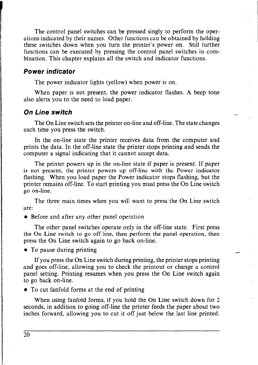
In Standard mode (when DIP switch l-6 is ON), the pitch selections
cycle as follows:
Pica
Elite
Condensed pica (17 characters per inch)
Condensed elite (20 characters per inch)
Proportional pica
Proportional elite
(10 characters per inch)
(12 characters per inch)
This is pica (10 characters per inch).
This is elite (12 characters per inch).
This is condensed pica (17 characters per inch).
T?k is condensed elite (20 characters per inch).
This is proportional pica.
This is proportional elite.
@We Z-2. Prlflt pitches SeleCtStHe trom the COW01 panel
1
21
Page 29
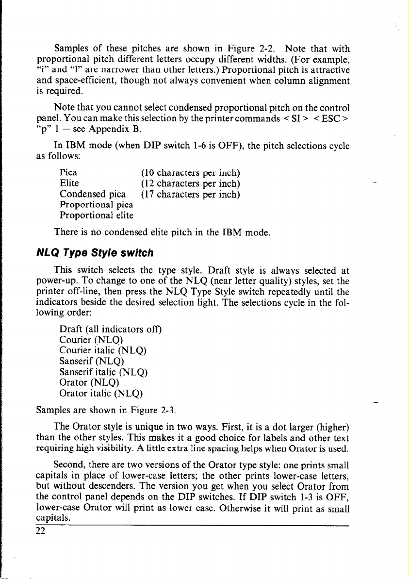
Samples of these pitches are shown in Figure 2-2. Note that with
proportional pitch different letters occupy different widths. (For example,
“i” and “1” are narrower than other letters.) Proportional pitch is attractive
and space-efficient, though not always convenient when column alignment
is required.
Note that you cannot select condensed proportional pitch on the control
panel. You can make this selection by the printer commands < SI >
< ESC >
“p” 1 - see Appendix B.
In IBM mode (when DIP switch l-6 is OFF), the pitch selections cycle
as follows:
Pica (10 characters per inch)
Elite (12 characters per inch)
Condensed pica
(17 characters per inch)
Proportional pica
Proportional elite
There is no condensed elite pitch in the IBM mode.
NLQ Type Style switch
This switch selects the type style. Draft style is always selected at
power-up. To change to one of the NLQ (near letter quality) styles, set the
printer off-line, then press the NLQ Type Style switch repeatedly until the
indicators beside the desired selection light. The selections cycle in the following order:
Draft (all indicators off)
Courier (NLQ)
Courier italic (NLQ)
Sanserif (NLQ)
Sanserif italic (NLQ)
Orator (NLQ)
Orator italic (NLQ)
Samples are shown in Figure 2-3.
The Orator style is unique in two ways. First, it is a dot larger (higher)
than the other styles. This makes it a good choice for labels and other text
requiring high visibility. A little extra line spacing helps when Orator is used.
Second, there are two versions of the Orator type style: one prints small
capitals in place of lower-case letters; the other prints lower-case letters,
but without descenders. The version you get when you select Orator from
the control panel depends on the DIP switches. If DIP switch 1-3 is OFF,
lower-case Orator will print as lower case. Otherwise it will print as small
capitals.
Page 30
.;
-/- l”i _i_ .y ::)
j..
<,j /_. 2, .+: +
i::i t.l t:\ 1. :i, t \ ’
“’ I
I 8,
This is near-letter-quality Courier.
This is Courier italic.
This is Sanserif.
This is Sanserif italic.
TtiIs IS ORATOR WITH SMALL CAPITALS.
THIS IS ORATOR ITALIC WITH SMALL CAPITALS.
This is Orator with lower case.
This is Orator italic with lower case.
Figure 2-3. Type styles selectable from the control panel
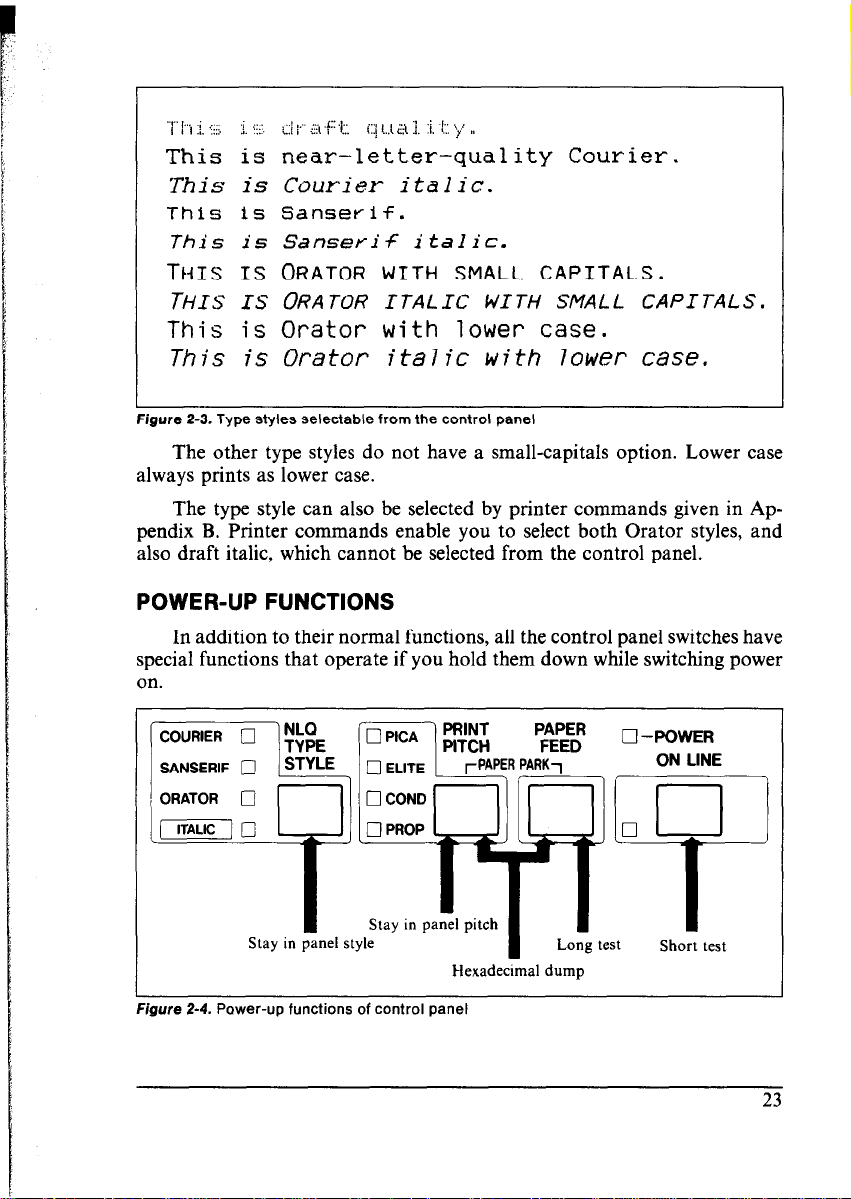
The other type styles do not have a small-capitals option. Lower case
always prints as lower case.
The type style can also be selected by printer commands given in Appendix B. Printer commands enable you to select both Orator styles, and
also draft italic, which cannot be selected from the control panel.
POWER-UP FUNCTIONS
In addition to their normal functions, all the control panel switches have
special functions that operate if you hold them down while switching power
on.
r
L
Prgure z-4. rower-up functions or control
Hexadecimal dump
panel
23
Page 31

Short test pattern: On Line switch
If held down during power-up, this switch prints a short test pattern
(shown in Chapter 1).
Long test pattern: Paper Feed switch
If held down during power-up, this switch prints a long test pattern.
The test cycles endlessly. To stop the test you must switch power off.
Stay in pane/ pitch: Print Pitch switch
By holding this switch down during power-up, you can prevent software
interference with the print pitch selected from the control panel. You will
hear an acknowledging beep as power comes on. After the beep tone, you
can set the printer off-line, select a print pitch, then return to on-line and
start printing. The pitch you selected will not be reset or otherwise changed
by any commands your software may issue.
Stay in pane/ Sty/e: NLQ Type Style switch
If held down during power-up, this switch prevents software interference
with the type style selected from the control panel. There will be an acknowledging beep, after which you can set the printer off-line, select a type
style, then return to the on-line state and start printing. The selected type
style will not be changed by any commands sent by software.
If you want to protect both the Print Pitch and NLQ Type Style settings
from software changes, press both switches during power-up. There will
be two acknowledging beeps.
Pressing these switches during power-up does not prevent you from
making any number of changes later from the control panel.
Hexadecima/ dump: Paper Feed and Print Pitch switches
This feature is useful for programmers who are debugging printing
programs and want to see the actual codes the printer is receiving. (Some
computers change the codes the programmer intended.)
1. Holding both the Paper Feed and Print Pitch switches down, turn power
ON. A beep tone will be heard.
2. Start printing. In place of the usual printout you will get a formatted
dump showing exactly what data the printer receives. Each line presents
sixteen characters, their hexadecimal codes to the left and printable
characters printed on the right.
24
Page 32

3. At the end of the hexadecimal dump, set the printer off-line with the
E
On Line switch. This is necessary to print the last line.
The following BASIC program is a simple test you can run in hexade-
cimal mode:
10 FOR I-O
20 LPRINT
*TO 255
CHR$(I);
30 NEXT I
40 LPRINT
50 END
If your system passes the codes directly to the printer without changing
them, you will get a printout like Figure 2-5.
10 11 12
20 21 22
30 51 32
40 41 42
50 51 52
60 61 62
70 71 72
80 El 82
90 91 92
A0 Al A2 c\3 A4 A5 A4 A7
BCI Hl 82 H3 84 H5 EL6 H7
co Cl c2
DO Dl D2 D3 D4 D5 D6 D7
EO El E2
FO Fl F2 F3 F4 F5 F6 F7
OD OA
13 14 15 16 17
23 24 25 26 27
53 34 J5 3‘ ,7
43 44 45 46 47
53 54 55 56 57
4; 64 65 66 67
75 74 75 76 77
83 84 85 86 87
95 94 95 96 97
C3 C4 C5 C6 C7
E3 E4 E5 E6 E7
18 19 1A 1H 1C 1D IE 1F
29 2A 26 2C 2D 2E
28
ZR 29 SA 3B ;C ZD SE 3F
48 49 4A 4B 4C 4D 4E 4F
59 3~ 56 5C 5D 5E
58
69 bA 66 6C 6D bE
68
78 79 ?A 7R 7C 7D 7E 7F
89 8A 86 8C ED 8E
88
99 9A 98 9C 9D 9E
98
A8 A9 AA AEI AC AD AE AF
BB B9 HA BR BC BD BE BF
C8 C9 CA CR CC CD CE CF
D8 D9 DA DB DC DD DE DF
E8 E9 EA EB EC ED EE EF
F8 F9 FA FB FC FD FE FF
Figure 2-5. Sample hexadecimal dump
Most BASICS, however, are not quite that straightforward. For example,
the IBM-PC prints the following.
CH:, 01
.
i
i
OF 10 11
20 21
30 31
40 41
50 51
60 61
70 71
80 81
90 91
A0 Al
HO 81
co Cl
DO Di
EO El E2
FO Fl
OD I:,‘?
03 04 ,:15 06 07 OR
02
12 13 14 15 16 17
23 24 25 26 27 28
22
3’1: 54 35 76 37 38
32
4J 44 45 46 47 40
42
53 54 55 56 57 58
52
63 64 65 66 67 68
62
7rI. 74 75 76 77 78
72
83 84 85 86 87 88
82
93 94 95 96 97 98
92
FIT A4 A5 A6 A7 A8
A2
B3 B4 B5 86 B7 H8
82
CI: c4 c5 Cb c7 CB
c2
DI: D4 D5 D6 D7 D8
Dr)
E3 E4 E5 E6 E7 E8
FS F4 F5 F6 F7 F8
F2
Figure 2-6. Sample hexadecimal dump with IBM-PC
09 CIA OR CC
18 19 16 1C 10 1E
29 2A 26 2C
39 3A 36
49 4A 4B
59 SA 56
69 6A 68 6C
79 7A 7B 7C
89 8A 8H 8C
99 9A 98
A9 AA AH
B9 BA BH
C9 CA CB CC CD
D? DA DB
E9 EA EB EC ED EE
F9 FA FR
OD OA
“D 2E
3C 3D 3E
4C 4D 4E
5C 5D 5E
6D bE
7D 7E
8D 8E
9C 9D 9E
AC AD AE
BC BD BE
CE
DC DD DE
FC FD FE
c
. . . . . . . . . . . . . . . .
2F
5F
6F
8F
9F
OE . . . . . . . . . . . . . . . .
1F . . . . . . . . . . . . . . . .
2F ‘“%5%&~ o*+,-./
3F 0123456789: ;<=:.?
4F BABCDEFGHIJKLMNO
5F PQH8T!JVWXYZC\l*~
6F ‘abcdefqhi jklmna
7F pqrstLivwt:yzI : 2,“.
8F . . . . . . . . . . . . . . . .
9F . . . . . . . . . . . . . . . .
AF . . . . . . . . . . . . . . . .
BF . . . . . . . . . . . . . . . .
CF . . . . . . . . . . . . . . . .
DF . . . . . . . . . . . . . . . .
EF . . . . . . . . . . . . . . . .
FF . . . . . . . . . . . . . . . .
’ “WB%&’ ( ) *+. -. /
0 123456789 : ; .:: = >?
@ABCDEFGHIJKLMNO
PQHSTUVWXYZE\l’-
‘abcde+ghiJklmno
pqrstuvwxyzc I:‘.
. .
2.5
L.
Page 33

When the IBM-PC BASIC interpreter sends hex code OD (carriage return) it adds an extra hex OA (line feed). Hex code 1A (end-of-file) also gets
special treatment: the interpreter does not send it at all. This can cause
problems in programs that generate graphics or download character data,
but there is a solution. Try changing line 20 in the preceding program and
adding the coding shown below.
Coding for IBM-PC with monochrome display:
20 GOSUB 100
100 O=INP(&H3BD)
110 OUT &H3BC,I
120 RETURN
Coding for IBM-PC with colour adaptor:
20 GOSUB 100
100 O=INP(&H379)
110 OUT &H378,1
120 RETURN
: IF 0<128 THEN 100
:OUT &H3BE,5 :OUT &H3BE,4
:IF 0<128
:OUT &H37A,5
THEN 100
:OUT &H37A,4
SWITCH COMBINATION FUNCTIONS
Several additional functions can be obtained by pressing the control
panel switches in combinations.
Reverse micro-feed
COURIER 0
SANSERIF 0
ORATOR 0
Top of form
Figure 2-7. Switch combination functions of control panel
!
Page 34

Paper parking: Print Pitch and Paper Feed switches
This procedure feeds the paper backward. It parks the fanfold form
at the back of the printer so that you can switch to single-sheet feeding (by
moving the release lever to the down position).
Before parking fanfold forms, tear off all but the last page, leaving less
(at least three inches less) than a full page showing above the top cover.
1. Press the On Line switch to set the printer off-line.
2. Press the Print Pitch switch and hold it down.
3. Press the Paper Feed switch. The paper will be fed out backward.
Page feed: Paper Feed and On Line switches
If you are using single sheets, this operation ejects the current page. If
you are using fanfold forms, it feeds to the top of the next page.
1. Press the On Line switch to set the printer off-line.
2. Press the Paper Feed switch and hold it down. The printer will start
performing successive line feeds.
3. Still holding the Paper Feed switch down, press the On Line switch, then
release both switches. The printer will smoothly eject the current page.
Top Of form: NLQ Type Style and On Line switches
When you turn on printer power, the top-of-form position is auto-
matically set to the current position.
of the page to be, you can change the top-of-form position as follows.
1. Press the On Line switch to set the printer off-line.
2. Move the paper to the desired top-of-form position by pressing the Paper
Feed switch, or by performing a forward or reverse micro-feed.
3. Press the NLQ Type Style switch and hold it down.
4. Press the On Line switch. The printer will beep to indicate that the
top-of-form position has been set.
If this is not where you want the top
Forward micro-feed: On Line and Paper Feed switches
For line alignment, you can feed the paper forward in very small in-
crements as follows:
1. Press the On Line switch to set the printer off-line.
2. Press the On Line switch again and hold it down.
3. Press the Paper Feed switch. The paper will start advancing in a series
of small steps. When you want to stop, release both switches.
Page 35

Reverse micro-fee& On Line and Print Pitch switches
You can also feed the paper in small increments in reverse, to return
to a higher position on the same page.
Note: With fanfold forms, do not try to return to a previous page. The
perforation may catch inside the printer.
Press the On Line switch to set the printer off-line.
1.
Press the On Line switch again and hold it down.
2.
Press the Print Pitch switch. The paper will start moving backwards in
3.
a series of small steps. When you want to stop, release both switches.
Left margin: NLQ Type Style and Print Pitch switches
Software almost always provides commands for controlling the margins,
so you will not usually have to set them from the control panel. When
necessary, however, you can set the left margin as follows.
Press the On Line switch to set the printer off-line.
1.
Press the NLQ Type Style switch and hold it down.
2.
3. Press the Print Pitch switch. The print head will make a short excursion
from the left end, then start advancing from left to right in a series of
steps, each equal to one pica character width (l/10”). When the print
head reaches the desired left margin position, release both switches,
The printer will beep to indicate that the margin has been set.
Right margin: NLQ Type Style and Paper Feed switches
You can also set the right margin.
1. Press the On Line switch to set the printer off-line.
2. Press the NLQ Type Style switch and hold it down.
3. :Press the Paper Feed switch. The print head will travel to the right end
-‘.-* ‘of the carriage, then start advancing from right to left in a series of l/10”
steps. When it reaches the desired right margin position, release both
switches. The printer will beep to indicate that the margin has been set.
Clearing the buffer: Print Pitch, On Line and Paper Feed switches
When DIP switch 2-l is ON, the printer stores received data in a large
memory buffer. This creates a problem when you want to abandon a printing
job and restart: the printer may be holding much more data in its buffer
than it has actually printed, and this unprinted data must be cleared out
before restarting. Turning power off is one way to clear the buffer, but there
is another way:
Page 36

1. Halt the printing program on the computer. If printing stops immediately, the buffer is clear and the rest of this procedure is unnecessary.
If printing does not stop, continue as follows:
2. Press the On Line switch to set the printer off-line. Printing will now
stop, but there may be data remaining in the buffer.
3. Press the Print Pitch switch and hold it down.
4. Press the On Line switch and hold it down.
5. Press the Paper Feed switch and hold it down. Continue holding all
three switches down. In about three seconds you will hear a beep tone
signaling that the buffer has been cleared.
6. Release all three switches, make any necessary control panel settings,
then set the printer back on-line.
It is essential to halt the printing program on the computer before you
go off-line. Otherwise, when you go back on-line the computer will start
sending data again and the printer will continue printing, with missing data
where the buffer was cleared.
29
Page 37

MEMO
30
-
Page 38

Chapter 3
USING THE PRINTER
WITH COMMERCIAL SOFTWARE
There is an abundance of commercial software available: spreadsheet
programs, word-processing programs, graphics programs, and more. This
printer will work with any program that supports a Star, Epson or IBM
dot-matrix printer. Before using the printer with commercial software,
however, there are two things you must do:
l Install the software so that it supports the printer
l Set the printer’s DIP switches to match the software
INSTALLING YOUR SOFTWARE
Most commercial software includes an installation program or routine
that you can run to customize the software to fit your hardware system.
Start by reading the explanation of the installation program in your software
manual.
Printer menu
The installation program usually offers a menu of printers from which
to choose. If you find this printer on the menu, select it.
If this printer is not listed, look for the Epson LX-800 or IBM Proprinter
II. If these are not listed, look for another Star, Epson or IBM printer. A
few of the choices you may see are given below in order of preference:
Star
NL-10 Epson LX-800
NP-10 FX-86e
NX-10/15 EX-800 Graphics Printer
ND-lo/15 LX-86
NR-lo/15 LX-80
IBM Proprinter II
Proprinter
Some menus are less explicit about model names but offer general descriptions such as “Star printer”, “Epson printer”, “IBM dot-matrix printer”,
“dot-matrix ASCII printer”, “Centronics-type printer”, “Draft printer”,
or “Standard printer”. Any of these selections should work. If you are not
sure of the right selection, it does not hurt to experiment. If you choose
wrong, you will get strange printing results, but don’t worry; just try a
different selection. Don’t pick any printer described as a daisywheel printer
or laser printer.
31
Page 39

A few installation programs may ask you not to select a printer but to
describe what your printer can do. The answers to the most often asked
questions are: Yes, this printer can do a backspace; and Yes, it can do a
hardware form feed.
Selecting (or describing) a printer is the main step in the installation
process and frequently the only step necessary. If you selected this printer
or any Star, Epson or IBM printer you should be able to use software
commands for all the standard printer functions, including bold or double-strike printing, underlining, subscripts, superscripts, margin control,
line-spacing control, and graphics.
Printer command options
Besides the standard printer functions, however, your printer has some
capabilities your software may not be aware of, including double- and
quadruple-size printing and the printing of special characters assigned to
control codes. Some software enables you to define these capabilities as user
options in the installation process. Read your software manual to find out
whether you can do this and if so, how.
The most useful thing you can do is to define a way to enter the escape
code < ESC > , which is the control character with decimal character code
27 (hexadecimal 1B). This code usually cannot be keyed in directly (pressing
the ESC key will not work). As an installation option, however, you may
be able to assign it to a function key or a special key combination. Doing
so will put the full power of the printer at your disposal.
Type styles
Some word-processing software has commands that enable you to
change type styles in the middle of a document without a printing pause.
To use these commands you must generally define the printer’s type styles
(fonts) during installation, by assigning them numbers for example. Read
your software manual for details, and refer to Appendix B for the relevant
printer commands.
Page width
Spreadsheet programs in particular may ask you to specify the printer’s
column width. The column width of this printer depends on the character
pitch used:
Pica
Elite
Condensed pica
Condensed elite
32
80 columns
96 columns
137 columns
160 columns (Standard mode only)
Page 40

The character pitch can be selected from the control panel before you
start printing, or possibly by an initialization sequence as described next.
initialization sequence
One of the installation options may be to specify the commands your
software sends at the beginning of each printing job. These commands are
called the “initialization sequence” or “setup string.” If necessary, you can
use the initialization sequence to adjust the margins to your paper size or
select a particular type style or pitch. You can look up the commands you
want in Appendix B.
For example, if you selected 96-column width for a spreadsheet program,
it would be convenient to add an elite pitch command to the initialization
sequence. Appendix B indicates that this command consists of the two
characters:
< ESC > “M”
which have decimal character codes 27 and 77 (hexadecimal 1B and 4D).
Your software manual or an on-screen prompt will explain how to place
these codes in the initialization sequence.
SETTING THE DIP SWITCHES
After completing the installation of your software, check the setting
of the printer’s DIP switches, in particular DIP switch l-6. If you selected
a Star or Epson printer on the installation menu, switch 1-6 should be ON
(the factory setting). If you selected an IBM printer, switch l-6 should be
OFF.
DIP switches l-2 (auto CR), l-7 (character set), 1-8 (auto LF), and 2-l
(RAM usage) are also related to your software. Read what your software
manual has to say about carriage returns, line feeds, character sets, and
downloading characters, and refer to the explanation at the end of Chapter
1.
USING YOUR SOFTWARE
With the installation and DIP switch settings correctly completed, you
are ready to entrust most of the control of your printer to your software.
However, there will still be some things you have to do yourself.
Page alignment
If you are printing on fanfold forms, the first thing to do before you
start printing is to align the top of the forms so that printing will start at
Page 41

the right position on the page, a short distance below the perforation. With
power off, you can align the forms by turning the platen knob. When power
is on, use the Paper Feed switch on the control panel.
Type style and pitch selection
If your software does not control the type style and pitch, you must
make these selections with printer commands or panel controls. The default
selections are draft style and pica pitch. To select a different style or pitch
from the control panel, proceed as follows:
1. Hold the NLQ Type Style or Print Pitch switch down when you turn
the printer’s power on. Hold both switches down if you intend to make
both settings. The printer will beep in acknowledgement as it powers
up*
2. Press the On Line switch to set the printer off-line.
3. To select a type style, press the NLQ Type Style switch one or more
times.
4. To select a print pitch, press the Print Pitch switch one or more times.
5. Press the On Line switch to set the printer back on-line.
Most programs begin each printing job by sending a command that resets
the printer. That is why you must press the NLQ Type Style and/or Print
Pitch switches as you power up. If you do not press these switches during
power-up, the reset command will reset your panel selections to draft style
and pica pitch.
If you want to change the type style or pitch in the middle of a printing
job, one way to do this is to insert a printing pause command in your file
at the point of the change. When the printer pauses, press the On Line switch
to go off-line. If the change occurs in the middle of a line, the printer will
print the first part of the line. Now make the change with the control panel
switches, set the printer back on-line, then command your software to resume
printing.
Another way is to embed printer commands in the file, as explained
next.
Embedding printer commands
Many word processors and other software lack commands for changing
type style, printing double-size characters, or printing in colour, and some
do not even support bold printing or italics. The printer therefore has
commands that can be embedded in documents to control these functions
without software help. The commands consist of a capital letter enclosed
in double parentheses, followed by a digit:
34
Page 42

Type style (Font): ((F))O Courier
((F))l Sanserif
((F))2
((F))3
((F))9 Draft
Orator with small capitals
Orator with lower case
Size:
Colour:
Bold:
Italic:
If you want to print a title in double-size Orator with small capitals,
then change to regular-size Courier for some text that includes italics, you
can use these commands as follows:
File as seen on computer screen:
Printer Commands
((F))O ((S))O
Type style, size, colour, bold print, and
((1))litalic ((1))Ocommands can be embedded
((1))lanywhere t(I))Oin a document.
((S))O Standard size
((S))l Double width
((S))2 Double height
((S))3
((C))0 Black
((C))1 Red
((C))2 Blue
((C))3 Violet
((C))4 Yellow
((C))5 Orange
((C))6 Green
((B))O Non-bold
((B)) 1 Bold
((I))0 Non-italic
((I))1 Italic
Double width and height
Printout:
,
*
PRINTER COMMANDS
Type style, size, colour, bold print, and
italic commands can be embedded
anywhere in a document.
Page 43

When you use these commands there are several points to note:
l The type style ((F)) and italic ((I)) commands are ignored if the NLQ
Type Style switch was held down when power was switched on.
l The bold command ((B))l gives double-strike printing. In draft mode
you may prefer to use emphasized printing, which requires a software
command or escape sequence.
l A line consisting of commands alone prints as a blank line.
l Software does not know that these commands are commands, so you
cannot trust your software to give you the correct line width. The printed
line may be considerably shorter than the line on the screen; the missing
space is the space that was occupied by the commands.
One way to handle the last problem is to prepare your document without
the commands, then insert them as a final step, with the margins released.
The find, replace, and copy functions of word-processing software can be
helpful here.
If you do not use these commands or the panel controls, the printer
will print standard-size, black, draft, non-bold, non-italic characters.
The printer supports various commands in addition to the above, such
as quadruple-size printing. Most of these other commands consist of the
escape code followed by one or more letters or numbers. If your software
enables you to place the escape code in your files, or if you were able to
define this as a user option during installation, you can also embed these
escape sequences. See Appendix B for further details.
After printing the first page of a long job, you may want to pause to
check that the printing is correctly formatted. Press the On Line switch,
setting the printer off-line. Printing will stop immediately. To resume
printing, press the On Line switch again.
-
If you need to abandon a printing job before it is finished, your software
should provide a command for this purpose. Another simple expedient is
to switch the printer’s power off.
-
-
Page 44

Chapter 4
USING THE PRINTER
WITH DOS AND BASIC
Although you will probably do most of your printing with the aid of
commercial software, at times you will want to employ direct commands
or programs of your own. This chapter will give you some ideas. Three
subjects are covered:
l Hard-copying the screen
l Programming the printer with DOS commands
l Programming the printer with BASIC
HARD-COPYING THE SCREEN (MS-DOS AND PC-DOS)
If your computer has a PRTSC (or PrtSc) key, there is an easy way to
get hard copy of the screen. Press the SHIFT and PRTSC keys. The printer
will print the current screen contents. The PRTSC key works both at the
system command level and while you are running application software.
Normally the PRTSC key prints only text data, but if your DOS system
includes a file named GRAPHICS.COM, you can hard-copy graphics displays, by first typing the command:
A >GRAPHICS
You will find that graphics printing takes considerably more time than
text printing. See your DOS manual for further information on the
GRAPHICS command.
At the DOS command level, there is also a simple way to have the printer
print hard copy continuously, instead of one screen at a time. Press the CTRL
key, hold it down, then also press the PRTSC key. If your computer does
not have a PRTSC key, press the CTRL and P keys. Nothing visible will
happen, but you have just switched on the print-screen function. After this,
the printer will hard-copy all text displayed. For example, try typing the
directory command:
A>DIR
You will obtain a printed directory.
37
Page 45

To switch printer output off, press CTRL-PRTSC or CTRL-P again.
Each time you press this key combination, hard copy toggles from on to
off or from off to on.
PROGRAMMING THE PRINTER WITH DOS COMMANDS
If your system includes the file PRINT.COM you can use the main
DOS printing command. Simply type the word PRINT followed by the name
of the file you want to print. To print a file named README.DOC, for
example, type:
A >PRINT README. DOC
The computer may respond with the following message, asking which
printer to use:
Name of list device [PRN]:
If your computer is connected to only one printer, press RETURN to
select the default choice (PRN). Printing will begin and the A> prompt
will reappear. You can execute other commands or programs while the file
is being printed.
A single PRINT command can print two or more files. List the tile names
consecutively on the same line, or use wild-card characters (* and ?). Each
file will be printed starting on a new page. The PRINT command also has
control options. For example, you can terminate a printing job in progress
with the /T option. (The printer may not stop printing immediately; it may
have considerable data stored ahead in its buffer.) For the /T option, type:
-
-
A >PRINT/T
See your DOS manual for further information about the PRINT
command. If your system does not include PRINT.COM, you can print files
by using the PRN device name in COPY or TYPE commands such as the
following:
A XOPY README. DOC PRN
A>TYPE README. DOC > PRN
COPY and TYPE do not permit you to execute other commands while
the file is printing.
38
Page 46

If you want a particular type style, print pitch, or right or left margin,
you can make these settings from the control panel before you start printing.
See Chapter 2.
If you print from the DOS command level very often, it will be advantageous to create a printer setup tile. Then instead of setting margins
etc. manually each time, you can complete the setup with a single command
from your computer. For example, you can create a tile containing printer
commands to set the right and left margins, select near letter quality, and
select elite pitch. You can find the commands in Appendix B. We suggest
the following:
l Near letter quality
l Elite pitch
l Left and right margins < ESC > “X” < 12 >
< ESC > “x” “1”
< ESC > “!”
cl>
< 92 >
< ESC > “!” < 1 > is a powerful command that, in addition to selecting
elite pitch, cancels unwanted features such as underlining which might be
left from previous commands. The angle brackets around the < 1 > indicate
character code 1, which is a control code, not the printable digit “1”.
< ESC > “X” < 12 >
< 92 > sets the left margin in column 12 and the
right margin in column 92. This will give a 6.7~inch, 80-column printed line
with a one-inch left margin. (Elite has 12 characters per inch). < 12 > is a
control code; < 92 > is the character “\“, as you can verify in Appendix
D.
You may want to place additional commands in this file, such as line
spacing and bottom margin commands. Or you may want to create a variety
of setup files with a different set of commands in each.
To avoid excess line feeds, you should place the commands on one line
in the setup file. You may or may not be able to generate a setup file with
word-processing software; it depends on whether your software lets you enter
control codes. If your system includes the file EDLIN.COM, however, you
can easily create a setup tile with the DOS line editor.
An appropriate name for this setup tile would be NLQELITE.DAT.
To use the DOS line editor, type the command EDLIN NLQELITE.DAT,
then type the underlined parts of the following display. Press RETURN
at the end of each line. Don’t type the symbol “ * “. This symbol means to
hold the CTRL key down while pressing the next key: for example, “V
means to type CTRL-V. “C means to type CTRL-C, which indicates the
end of the input.
A >EDLIN NLQELITE . DAT
New file
Page 47

*I
l:*-V[xl^V[!“VA^V[X^VL\
2:*-c
“E
-
-
^V indicates that the following character is a control code. ^V[ enters
the < ESC> code. < ESC > has character code 27, and “[” is the 27th
character in ASCII sequence from A. Similarly, “VA enters the control
code < 1 > and “VL enters the control code < 12 > . See your DOS manual
if you need further information about EDLIN.
You can now set up the printer by sending it the file NLQELITE.DAT.
To avoid unnecessary logging of commands, switch hard-copy output off
(by pressing CTRL-PRTSC if hard copy is on). To print the file
README.DOC in NLQ elite type, give the following two commands:
A>COPY NLQELITE.DAT PRN
A >PRINT README. DOC
For greater convenience you can make a batch file that will set up the
printer and print any specified file with a single command. To create such
a batch file with the name NLQPRINT.BAT, type in the first four lines shown
next. ^Z means to press the CTRL and Z keys simultaneously. To use this
file to print README.DOC, type the fifth line.
A>COPY CON NLQPRINT.BAT
COPY NLQELITE.DAT PRN
PRINT %1
^Z
A>NLQPRINT README.DOC
_
.-
The first above line is a copy command from the CONsole screen to
a file named NLQPRINT.BAT. The next two lines are the contents of this
file. The %l is a dummy parameter: whatever tile name you type after
NLQPRINT will be substituted for %l and printed.
PROGRAMMING THE PRINTER WITH BASIC
As an example of programming the printer in Microsoft BASIC, we
have listed the program for the IBM-PC that printed the sample on the
foldout inside the back cover. This program runs in the printer’s Standard
mode (DIP switch l-6 ON).
40
Page 48

You will note that this program avoids the printer’s double-parenthesis
commands. To change colours, for example, it uses the escape sequence
E$: “r”;
CHR$(n), where E$ is predefined as CHR$(27), instead of the
equivalent command ((C))n. The double-parenthesis commands are great
for embedding in documents, but they are less convenient in programs. In
their simplest form they cannot be listed; instead of listing them, the printer
executes them.
1000
1010
1020
1030
1040
1050
1060
1070
1080
1090
1100
1110
1120
1130
1140
1150
1160
1170
1180
1190
1200
1210
1220
1230
1240
1250
1260
1270
1280
1290
1300
1310
1320
1330
1340
1350
1360
1370
1380
1390
1400
’ Set control codes
E$-CHR$(27)
D$-E$+“xO”
‘Escape code
‘Draft quality
N$-E$t”xl” ‘Near letter quality
C$-E$t”kO”+N$
‘Courier
S$-E$t”kl”tN$ ‘Sanserif
Ol$-E$+“k2”+N$
‘Orator with small capitals
028sE$+“k3”+N$ ‘Orator with lower case
H$KHR$(B)
P$-E$+“P”
‘Horizontal tab
‘Pica pitch
’ Start printing
WIDTH “LPTl * ” ,255
LPRINT E$;“D”;CHR$(3);CHR$(20);CHR$(O) ‘Set HT
LPRINT C$; “Type styles are : ”
LPRINT H$ ; D$ ; “Draft characters, ”
LPRINT H$; C$; “Courier characters, ”
LPRINT H$; S$ ; “Sanseri f characters, ”
LPRINT H$;Ol$;“Orator with small capitals, or H
LPRINT H$;02$; ”
with lower case characters,”
LPRINT E$ ; “4” ; ‘Select italics
LPRINT H$;02$;“and “;Ol$;“italics “;S$;“for “;
LPRINT C$;“all “;D$;“styles.”
LPRINT E$ ; “5”
‘Cancel italics
LPRINT C$; “Print pitches are : ”
LPRINT H$;P$;“Pica pitch,“;
LPRINT H$;E$; “M”; “Elite pitch, ”
LPRINT H$;CHR$(15); ‘Condensed pitch
LPRINT P$; “Condensed pica pitch, ‘I;
LPRINT H$ ; E$ ; “M” ;
“Condensed elite pitch,“;
LPRINT P$; ‘Pica pitch
LPRINT CHR$ ( 18)
LPRINT H$;E$; “~1”;
‘Cancel condensed print
‘Select proportional spacing
LPRINT “Proportional spacing for all pitches,”
LPRINT E$ ; “~0”
‘Cancel proportional spacing
LPRINT H$ ; E$ ; “Wl ” ; “Expanded, ” ; E$ ; “WO” ;
LPRINT E$ ; “~1” ; “Doub 1 e-height , ” ; E$ ; “~0 ”
LPRINT H$;E$;“h”;CHR$(l);“Double-sized,”
LPRINT H$;E$;“h”;CHR$(2);“Quad-sized.“;
LPRIN’T E$ ; “h” ; CHR$ (0 )
LPRINT :LPRINT :LPRINT
LPRINT C$; “Colour printing:”
41
Page 49

1410 LPRINT
_
1420 LPRINT H$;E$;"wl";E$;"r";CHR$(l);"RED, 'I;
1430 LPRINT E$;"r";CHR$(2);"BLUE. I';
1440 LPRINT E$;"r";CHR$(3);"VIOLET. ";
1450 LPRINT E$;"r";CHR$(4);"YELLOW,"
1460 LPRINT
1470 LPRINT H$;E$;"r";CHR$(5);"ORANGE, ";
1480 LPRINT E$;"r";CHR$(6);"GREEN, ";
1490 LPRINT E$;"r";CHR$(O);"and
BLACK."
1500 LPRINT E$;"wO"
1510 LPRINT E$;"Q";CHR$(47) 'Set right margin
1520 LPRINT C$;"Various line and character spacings:"
1530 LPRINT E$;"al"
'Center text
1540 FOR I=1 TO 7
1550 LPRINT E$;"A";CHR$(I); 'Set line spacing
1560 LPRINT E$;" ";CHR$(I);
'Increase character space 1570 LPRINT E$;"r";CHR$(I-1); 'Select colour
1580 LPRINT "THE SPACING HAS CHANGED"
1590 NEXT I
1600 FOR I-7 TO 1 STEP -1
1610 LPRINT E$;"A";CHR$(I);
1620 LPRINT E$;" ";CHR$(I);
1630 LPRINT E$;"r";CHR$(I-1);
1640 LPRINT "THE SPACING HAS CHANGED"
1650 NEXT I
1660 LPRINT E$;"aO"
'Left justify
1670 LPRINT E$;"3";CHR$(36); 'Set l/6" line spacing
1680 LPRINT E$;" ";CHR$(O);
'Normal character space
1690 LPRINT :LPRINT
1700 LPRINT C$;"Other features:"
1710 LPRINT H$;E$;"E";"Emphasized";E$;"F";", 'I;
1720 LPRINT E$;"G";"Double-strike";E$;"H";","
1730 LPRINT H$;E$;"-l";"Underlining";E$;"-O";", 'I;
1740 LPRINT E$;"~1";"Overlining";E$;"~O";","
1750 LPRINT H$;E$;"SO";"SUPERSCRIPT";E$;"T";". 'I;
1760 LPRINT E$;"S1";"SUBSCRIPT";E$;"T";","
1770 GOSUB 2130
1780 LPRINT H$;C$;"Download
1790 LPRINT D$;E$;"%l";
characters: 'I;
Select download character 1800 FOR I=1 TO 7
1810 LPRINT E$;"r";CHR$(I-1
1820 LPRINT CHR$(60);
'Change colour
1
;
Print download character
1830 NEXT I
1840 LPRINT E$;"%O";
Select normal character
1850 GOSUB 2230
1860 LPRINT C$;E$;"%l";
'Select download character
1870 FOR I-1 TO 7
1880 LPRINT E$;"r";CHR$(I-1);
1890 LPRINT CHR$(60);
'Change colour
'Print download character
1900 NEXT I
42
Page 50

1910 LPRINT E$;"r";CHR$(O);
1920 LPRINT E$;"%O"
'Select normal character
1930 LPRINT H$;C$;"Dot graphics:";
1940 DIM LOG0$(4)
1950 RESTORE 2450
1960 FOR ROW-1 TO 4
1970 FOR COL-1 TO 100
1980 READ DG
1990 LOGO$(ROW)=LOGO$(ROW)tCHR$(DG)
NEXT COL
2000
2010 NEXT ROW
2020 LPRINT E$;"A";CHR$(8);
'Set 8/72" line spacing
2030 FOR ROW-1 TO 4
LPRINT H$;H$;
2040
2050 LPRINT E$;"*";CHR$(O);
LPRINT CHR$(lOO);CHR$(O);
2060
LPRINT LOGO$(ROW)
2070
NEXT ROW
2080
2090 LPRINT E$;"O"
END
2100
2110
2120
2130
2140 LPRINT D$;E$;":"
2150
2160
2170
2180
2190
2200
2210
2220
'
' SUBROUTINES
' Define draft download character
;CHR$(O);CHR$(O);CHR$(O);
LPRINT E$;"&";CHR$(O);CHR$(6O);CHR$(60);
RESTORE 2340
FOR M-O TO 11
READ MM
LPRINT CHR$(MM);
NEXT M
RETURN
4
'Select normal density
'Initialize printer
2230 ' Define NLQ download character
2240 LPRINT C$;E$;":";
LPRINT E$;"&";CHR5(0);CHR$(60);CHR$(60);
2250
RESTORE 2380
2260
FOR M-O TO 46
2270
READ MM
2280
LPRINT CHR$(MM);
2290
NEXT M
2300
RETURN
2310
2320
2330
2340
2350
2360
2370
2380
2390
2400
'
' DATA
' Draft download character data
DATA 139,124, 0, 66. 4, 64, 36, 16, 2, 16
DATA 12, 0
'
’ NLQ download character data
DATA 128, 14, 16, 38, 1. 70, 1, 70. 0,126
DATA 0, 0, 70. 0. 38. 0, 22. 9. 6. 9
CHR$(O);CHR$(O);CHR$(O);
43
p”
Page 51

2410
2420
2430
DATA
DATA
DATA
6, 8. 6. 0, 28, 32, 14, 64, 14, 0
14. 0,124, 0, 0, 12, 64, 12, 32, 14
16, 14, 0. 14, 0, 12, 0
2440 '
2450 '
Dot graphics data
2460 DATA 0, 0, 0. 0, 1. 3, 7. 7. 7. 15
2470 DATA 14, 14, 14. 14, 14, 7, 7. 3, 3, 15
2480 DATA
2490 DATA
2500 DATA
2510 DATA
2520 DATA
2530
DATA
2540
DATA
2550 DATA
2560
DATA
2570
DATA
2580 DATA
2590 DATA
15, 15, 0. 0, 0. 0, 0, 0. 0. 0
0, 1, 3. 3. 7. 7, 15, 14, 14, 14
14, 15, 7. 7. 7. 3, 0. 0. 0, 0
0, 0. 0. 0. 0, 0, 0, 0, 0, 0
0, 0, 0, 0, 0. 0, 0, 0. 0. 0
1. 3. 7, 7, 7, 15, 14, 14, 14, 14
14. 7. 7, 3, 3, 15, 15. 15. 0, 0
0, 0, 0. 0. 0. 0. 0, 0. 0, 0
0, 0, 60.255.255.255.255.255.143. 15
7, 7, 7, 7. 3. 3, 3,131,193,241
240,240, 0. 0, 0. 0, 0. 0. 0. 1
121,253,253,255.255,255,143~ 7. 7. 7
2600 DATA 31,253,252.248,248.240.192, 0, 7, 15
2610 DATA
2620 DATA
2630 DATA
2640 DATA
2650 DATA
2660 DATA
2670 DATA
2680 DATA
2690 DATA
31, 31, 15, 7. 3. 0. 0. 0. 0, 0
0, 0, 0. 0, 0, 0. 0. 0, 60,255
255,255,255.255,143. 15, 7. 7. 7, 7
3. 3, 3,131,193,241,240,240. 0. 0
0, 0. 0. 0, 0. 0. 0. 0. 0, 0
0, 31, 31, 3.129.128.192.192.192.192
192,224,224.224,224,240.255,255,255.255
255.127. 0, 0. 0. 0, 63,127,255,255
255,255,193,128,128.128,128,192,224~240
2700 DATA 252,255.255,255.127, 63. 31, 7. 7, 31
2710 DATA
2720
2730 DATA
2740 DATA
2750 DATA
2760
2770 DATA
2780 DATA
2790 DATA
2800 DATA
2811-j DATA
2820
2830 DATA
2840 DATA
2850 DATA
254,252,248.224,128, 0, 0, 3, 7. 7
DATA
7, 3, 0, 0, 0. 0. 0, 31, 31. 3
129,128,192,192.192,192,192,224,224,224
224,240,255,255.255.255.255,127, 0, 0
0, 0, 0, 0. 0, 0. 0. 0, 0. 0
DATA 0,248,248,240,224,224.112.112,112, 56, 56
56, 56, 56,120,120,240.240.224,224,192
128, 0. 0, 0, 0, 0,192,224,240,240
240,248,248.248,120~120. 56. 56. 56. 56
48,112,224,224,224,224,240,240,248~248
120,120, 56, 56, 56. 56,120.240,224.224
DATA 192,128. 0, 0. 0, 0. 0,248,248.240
224,224,112,112, 56. 56. 56. 56, 56.120
120,240,240.224.224,192,128, 0, 0, 0
0, 0. 0, 0. 0, 0. 0, 0, 0. 0
How the program works
This program begins by assigning a number of printer commands to
BASIC string variables (lines 1000 to 1090). You can find most of these
commands near the beginning of Appendix B.
44
Page 52
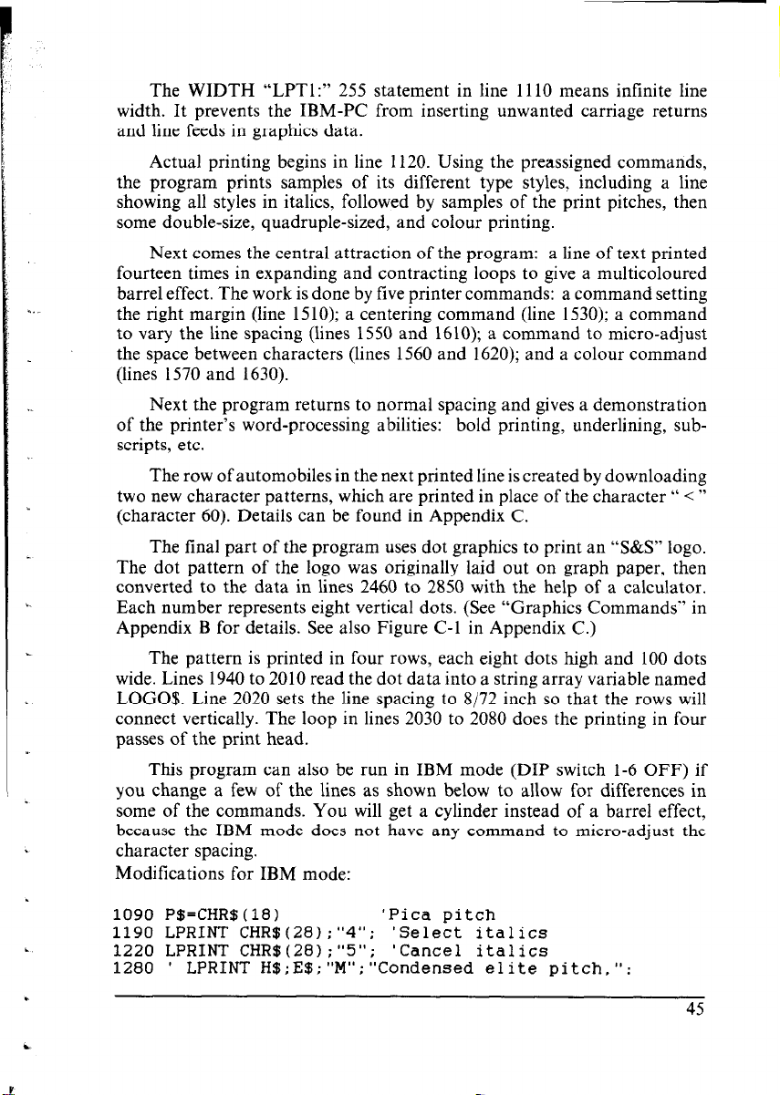
The WIDTH “LPTl:” 255 statement in line 1110 means infinite line
Y
width. It prevents the IBM-PC from inserting unwanted carriage returns
and line feeds in graphics data.
Actual printing begins in line 1120. Using the preassigned commands,
the program prints samples of its different type styles, including a line
showing all styles in italics, followed by samples of the print pitches, then
some double-size, quadruple-sized, and colour printing.
Next comes the central attraction of the program: a line of text printed
fourteen times in expanding and contracting loops to give a multicoloured
barrel effect. The work is done by live printer commands: a command setting
the right margin (line 1510); a centering command (line 1530); a command
to vary the line spacing (lines 1550 and 1610); a command to micro-adjust
the space between characters (lines 1560 and 1620); and a colour command
(lines 1570 and 1630).
Next the program returns to normal spacing and gives a demonstration
of the printer’s word-processing abilities: bold printing, underlining, sub-
scripts, etc.
The row of automobiles in the next printed line is created by downloading
two new character patterns, which are printed in place of the character “ < ”
(character 60). Details can be found in Appendix C.
The final part of the program uses dot graphics to print an “S&S” logo.
The dot pattern of the logo was originally laid out on graph paper, then
converted to the data in lines 2460 to 2850 with the help of a calculator.
Each number represents eight vertical dots. (See “Graphics Commands” in
Appendix B for details. See also Figure C-l in Appendix C.)
The pattern is printed in four rows, each eight dots high and 100 dots
wide. Lines 1940 to 2010 read the dot data into a string array variable named
LOGO$. Line 2020 sets the line spacing to 8/72 inch so that the rows will
connect vertically. The loop in lines 2030 to 2080 does the printing in four
passes of the print head.
This program can also be run in IBM mode (DIP switch l-6 OFF) if
you change a few of the lines as shown below to allow for differences in
some of the commands. You will get a cylinder instead of a barrel effect,
because the IBM mode does not have any command to micro-adjust the
character spacing.
Modifications for IBM mode:
1090 P$=CHR$(lB)
'Pica pitch
1190 LPRINT CHR$(28);"4"; 'Select italics
1220 LPRINT CHR$(28);"5"; 'Cancel italics
' LPRINT H$;E$;"M"; "Condensed elite pitch,":
1280
45
Page 53

1510 LPRINT CHR$(28);"Q";CHR$(47) 'Set right margin
1550 LPRINT E$;"A";CHR$(I);E$;"2"; 'Set line spacing
1560 '
LPRINT E$;" ";CHR$(I); 'Increase character space
1610 LPRINT E$;"A";CHR$(I);E$;"2":
1620 ' LPRINT E$;" ";CHR$(I);
2020 LPRINT E$;"A";CHR$(B);E$;"2": 'Set 8/72" spacing
2140 LPRINT D$;CHR$(28);":";CHR$(O);CHR$(O~;CHR$(O);
2240 LPRINT C$;CHR$(28);":";CHR$(O);CHR$o;CHR$(O~;CHR$(O~;
2250 LPRINT E$;"&";CHR$(O);CHR$(6O~;CHR$~6O);
46
Page 54

Chapter 5
MAINTENANCE
AND TROU5LESHOOTlNG
Subjects covered in Chapter 5 include -
l Cleaning the printer
l Replacing the ribbon
l Replacing the print head
l Troubleshooting
Dust and heat will make any mechanism wear more quickly. The best
maintenance is preventive, and the first step is correct location of the printer.
This is covered in greater detail in Chapter 1, but in general an environment
comfortable for humans is best for both the computer and the printer.
CLEANING THE PRINTER
Cleaning the printer regularly will prolong its service life. Use a damp
cloth on the exterior every week or so. For stubborn dirt, you may moisten
the cloth with alcohol or water containing a mild detergent, but be careful
not to spill any liquid into the interior of the printer.
Use a soft brush to remove paper dust and lint from the interior. A small
vacuum cleaner can also make this task easier, but be very careful not to
bend or injure any electronic parts or wiring. The printer contains delicate
electronic parts, so only clean those places where you have easy access.
REPLACING THE RIBBON
The printer uses an endless-type colour ribbon cartridge in which the
ribbon is recycled automatically. When the print becomes faint, it is time
to replace the ribbon cartridge.
To remove the old cartridge, take off the top cover and press the ribbon
release catch toward you with your index finger. Once the ribbon is free
of the print head, the cartridge lifts out easily. To fit the new cartridge,
guide the ribbon between the print head and the metal platen guard, then
set the cartridge in place on the carriage and press down lightly. The release
catch will lock automatically. See Figure 5-l.
Page 55

REPLACING THE PRINT HEAD
The dot matrix print head has a life of about 200 million dots, or years
of normal use. When printing is too light even after replacing the ribbon,
you’ll know that the print head has reached the end of its service life. To
replace the print head, follow the procedure below.
As you remove the old print head, note carefully how the cable is
threaded, so that you can thread the new cable in the same way.
Caution: When replacing the print head, be careful not to touch the brass
gear on the carriage.
Warning: The print head becomes hot during operation. If you have been
using the printer, wait awhile so that the print head can cool
off.
1. Turn power OFF and unplug the power cord.
2. Remove the top cover and ribbon cartridge.
3. Move the print head carriage toward the right until you can see the
connector cover. Remove the connector cover and pull the cable free
from the connector.
4. Remove the gear cover by pushing the fulcrums on both sides. At this
time, take care not to lose the spring.
5. Unscrew the two screws that hold the print head in place and set them
aside.
-
48
Page 56

6. Disengage the cable from the tabs holding it down, then remove the
print head.
7. For easy installation of the new print head, move the carriage toward
the left end of the rail.
8. Place the new print head on its support, seating it on the two pins.
9. Thread the new cable the same way as the old, securing it under the
tabs on the print head carriage.
Connector cover
Figure 5-2. Replacing the print head
10. Plug the cable into the connector, inserting it as far as it will go.
11. Fasten the print head down with the two screws.
12. Replace the spring and the gear cover in place.
13. Move the carriage back toward the right and replace the connector cover.
Slide the connector cover to the left until it locks into place.
14. Replace the ribbon cartridge and top cover, and plug the power cord
back in.
49
Page 57

TROUBLESHOOTING
H If the printer doesn’t print:
l Check the Power and On Line indicators. Both must be on.
l Check that the interface cable is securely plugged in at the computer and
printer ends.
l Make a test print. (Turn power OFF, hold the On Line or Paper Feed
switch down, then turn power ON.) If the test print succeeds, the problem
is not with the printer; try a different printing command, or try using a
different cable. If the test print fails, have the printer checked by a qualified
serviceman.
n If fanfold paper becomes stuck:
l Turn power off, take off the rear cover, remove the paper, and reload
the paper as described in Chapter 1.
l Make sure the paper is placed so that it feeds into the printer straight.
n If label paper becomes stuck:
l Have a qualified serviceman remove any label paper that adheres inside
the printer. Do not attempt to remove it yourself.
l Avoid using label paper with any exposed adhesive areas.
n If printing is faint, incomplete, or unclear:
l Check that the ribbon cartridge is installed correctly. If the ribbon
cartridge is old, replace it.
l Adjust the printing gap. See Chapter 1.
l If ribbon replacement or gap adjustment does not solve the problem,
replace the print head.
n If a// text is printed on the same line:
l Set DIP switch 1-8 to the OFF (front) position.
-
n If line spacing is twice as wide as expected:
l Set DIP switch l-8 to the ON (back) position.
n If you can’t print to the end of the page:
l This is normal. The printer’s paper-out detector detects the end of the
paper and stops printing about an inch above the end.
e You can make the printer ignore the paper-out detector by setting DIP
switch l-5 to the OFF (front) position, or by using the < ESC > “8” printer
command.
Page 58

n If the printed characters don’t match the characters on the
screen:
l Check DIP switches 2-2 to 2-4. When these switches are not all ON (back),
an international character set is selected and some ASCII symbols are
changed to other characters. See Appendix D.
l Some software is not able to display international characters on the screen.
If you use an international character set you may want to paste labels
on the keyboard.
l If you are using the IBM mode, check DIP switch l-7. Some international
characters and symbols do not print when this switch is OFF (front).
n If some printer commands are ignored or executed incor-
rectly:
l Check that the setting of DIP switch 1-6 matches the type of printer your
software supports: ON (back) for Star or Epson; OFF (front) for IBM.
l A few commands are mutually exclusive. For example, you cannot get
emphasized condensed printing.
n If you have problems with horizontal tabulation:
l Don’t change the margins after setting tabs.
l Don’t change the print pitch after setting tabs. The physical positions
of the tab stops do not adjust to the new print pitch.
n If you have problems with graphics:
l If you are using commercial software, check that it supports this printer,
or a Star, Epson or IBM printer, and that DIP switch l-6 is set correctly:
ON (back) for Star or Epson; OFF (front) for IBM.
l Use a hex dump to verify the codes the printer is receiving. See the graphics
command descriptions in Appendix B. Some computers insert unwanted
commands (such as carriage returns and line feeds) in graphics data, or
change the values of certain codes.
l BASIC programs may require a WIDTH statement. Check your BASIC
manual.
n If you have problems with download characters:
l Check that DIP switch 2-l is OFF (front).
l Make the same checks as for graphics problems.
Page 59

MEMO
Page 60

TECHNICAL SPEClHCA T/Oh/S
H Printing Mechanism
Printing method
Printing speed
Printing direction
Serial impact dot matrix
120 characters per second (draft pica)
30 characters per second (NLQ pica)
Draft:
(selectable), logic seeking
NLQ and graphics: unidirectional, logic
seeking
bi-directional or unidirectional
Print head
Ribbon
Paper feed
Paper feed speed
n /nterface and Emulation
Interface
Data buffer
Emulation modes
H Switches and indicators
Power switch
Control panel
9 Pins
Life: 200 million dots
Black/blue/red/yellow fabric ribbon car-
tridge
Life: 1 million draft characters/colour
Friction and push-tractor feed
Semiautomatic sheet loading
2.7 inches/second (during page feed)
Centronics-compatible, 7 or 8 bit,
TTL-level
8K bytes when not used for download
characters
l-Line buffer when using download
Epson LX-800 and IBM Proprinter II
Rocker switch
4 Membrane switches, 10 LED indicators
53
Page 61

DIP switches
Special features
12 pins
Panel pitch/style lock-in
Forward and reverse micro-feed
Paper parking
Hexadecimal dump
W Co/our Printing
Colours
W Dot Matrix Size
Character matrix
Bit-image graphics
n Character Sets
Standard character set
IBM character set
Black, red, blue, violet, yellow, orange,
green
9 x 9 dots (Draft pica)
18 x 23 dots (Courier and Orator pica)
18 x 18 dots (Sanserif pica, elite)
12 x 11 dots (IBM block graphics, pica)
18 x 19 dots (Courier and Orator elite)
18 x 12 dots (Condensed pica)
18 x 10 dots (Condensed elite)
8 x 480 dots at 60 dpi (Single density)
9 x 480 dots at 60 dpi (Single density)
8 x 576 dots at 72 dpi (Plotter mode)
8 x 640 dots at 80 dpi (CRT I)
8 x 720 dots at 90 dpi (CRT II)
8 x 960 dots at 120 dpi (Double density)
9 x 960 dots at 120 dpi (Double density)
8 x 960 dots at 120 dpi (High speed)
8 x 1920 dots at 240 dpi (Quadruple density)
96 ASCII characters
244 characters (ASCII, international
characters, symbols, block graphics)
.-
-
-
Download characters
International character sets
54
Max. 192 (draft) or 78 (NLQ)
14 sets (USA, France, Germany, England,
Denmark I, Denmark II, Sweden, Italy,
Spain I, Spain II, Japan, Norway, Latin
America, Denmark/Norway)
Page 62

n Type Styles and Pitches
Draft type styles
NLQ type styles
Extra-large characters
Draft, draft italic
Courier, Sanserif, Orator (with lower case
or small capitals), and italic versions of
these
Double width, double height, double width
and height, quadruple width and height
Print pitches
Pica (10 cpi)
Elite (12 cpi)
Condensed pica (17 cpi)
Condensed elite (20 cpi) (Standard mode
only)
Proportional spacing can be selected for
each of the above
Line spacing
l/6 inch (standard)
l/8, n/72, or n/216 inch (programmable)
Column width
8 inches
Pica: 80 characters
Elite: 96 characters
Condensed pica: 137 characters
Condensed elite: 160 characters
n Paper Specifications
Single sheets
140 to 216 mm (5.5 to 8.5 inches) wide,
0.07 to 0.10 mm thick
Fanfold paper
102 to 254 mm (4 to 10 inches) wide
0.07 to 0.10 mm thick (single-ply)
Max. 0.28 mm thick (3-ply)
Number of copies
Max. 3 (original + 2 copies)
n Dimensions and Weight
Dimensions
Width 384 mm (15.1 inches)
Depth 287.5 mm (11.3 inches)
Height 108 mm (4.3 inches)
i.
Weight
4.7 kg (10.3 pounds)
‘.
55
Page 63

n Electrical Specifications
-
Line voltage
120 VAC f 10%
220 VAC + 10%
240 VAC + 10%
(varies according to the country of pur-
chase)
Line frequency
Power consumption
Insulation resistance
50 or 60 Hz
Typ. 30 W, Max. 60 W
10 megohms between AC power line and
chassis
Dielectric strength
Withstands 1 kVAC rms at 50 or 60 Hz
between AC power line and chassis for
at least 1 minute
n Environmental Requirements
Operating temperature
Operating humidity
Storage temperature
Storage humidity
5 to 40°C (41 to 104°F)
10% to 80% (no condensation)
- 30 to 65°C (- 22 to 149°F)
10% to 95% (at 40°C) (no condensation)
n Option
Automatic sheet feeder
n lnterface Signals
Pin No.
1 STROBEIN
2
3
4
5 DATA” ThT
k
7
8
9
10
Signal
Name
Direction Function
DATA1 IN
DATA2 IN
DATA3 IN Eight-bit character data. DATA8 is the
.A* , II\
-‘*c I TXT
DA~.AJ
DATA6
DATA7
DATA8
KFR
56
1lY
IN
IN
IN
01
Goes from High to Low (for at least 0.5
microseconds) when data are valid.
most sismificant bit: DATA1 is the least
--_-- --51-~--..~~ -~~, ~
1 significant bit. High is logic 1 and Low is 1
- logic 0.
JT
1 5-Microsecond Low pulse acknowledges 1
1 receipt of data.
1
1
I
Page 64

Page 65

MEMO
Page 66

PRINTER CONTROL COMMANDS
This appendix describes the printer’s control commands. The commands are
arranged by function. The name of each command is followed by a table like the
one below:
Mode
Both
ASCII
<ESC> “X”
<ESC> “X”
Mode:
Decimal
I‘ 1”
Cl>
27 120 49 1B 78 31
27 120 I IB 78 01
Indicates the mode in which the command is recognized.
Std.
IBM
Standard mode (DIP switch 1-6 on)
IBM mode (DIP switch 1-6 off)
Hexadecimal
Both Both standard and IBM modes
ASCII:
Indicates the ASCII coding of the command. Control
characters are enclosed in pointed brackets: For example,
< 0 > means character code 0.
Decimal:
Gives the command in decimal character codes.
Hexadecimal: Gives the command in hexadecimal character codes.
Parameters for which values must be supplied are indicated by italic letters
such as n.
Many commands have alternative forms. Some commands use < ESC >
(character code 27) in Standard mode and < FS > (character code 28) in IBM
mode. Other commands have parameters that can be specified as either character
codes or digit characters, like the parameter 1 in the sample command above.
FONT CONTROL COMMANDS
Select draft quality characters
Mode
Both <ESC>
IBM
ASCII
‘C .,
( (
<ESC> (‘X”
< ESC > “I” “0”
< ESC >
Changes from near letter quality to draft quality. Ignored if the NLQ
Type Style switch was pressed during power-up.
“F” “)” “)”
‘I 0
&IX” “0”
“I”
co>
co>
Decimal
40 40 70 41 41 57
“9”
27 120 48 1B 78 30
27 120 0 IB 78 00
27 73 48 1B 49 30
27 73 0 1B 49 00
Hexadecimal
28 28 46 29 29 39
59
Page 67

Select draft elite characters
_-
Mode ASCII
IBM
<ESC> “I” “ ”
< ESC >
“I”
<I>
Changes to draft quality characters with elite pitch (12 cpi). Ignored if
the NLQ Type Style switch was pressed during power-up.
Select NLQ characters
Mode
Both
ASCII
<ESC> &lx,’ %‘ ”
<ESC> “X”
<I> 27 120 1
Changes from draft quality to near letter quality. The initial NLQ type
style is Courier unless a different style has been selected by a preceding
command. Ignored if the NLQ Type Style switch was pressed during
power-up.
Select NLQ type sty/e
Mode ASCII
Both
<ESC> “k” n
Selects an NLQ type style according to the value of n. In draft mode,
this command remains dormant and takes effect later when NLQ is se-
lected by <ESC>
pressed during power-up.
n Type style
0 Courier (initial value)
1 Sanserif
2 Orator with small capitals
3 Orator with lower case
Decimal
I 21 13 49 IB 49 31
27 73 1 1B 49 01
Decimal Hexadecimal
I 27 120 49
Decimal Hexadecimal
27 107 n 1B 6B n
Hexadecimal
1B 78 31
IB 78 01
“x” 1. Ignored if the NLQ Type Style switch was
Select Courier characters
Mode
Both “(V “(”
IBM
60
ASCII
‘.F” “)” “)” “0” 40 40 70 41
<ESC>
< ESC >
< ESC >
< ESC >
“” 1 “3”
“I” <3>
“I” “7”
“I” <7>
Changes to the Courier NLQ font. Ignored if the NLQ Type Style switch
was pressed during power-up.
Decimal
27 13 51
27 73 3
27 73 55
27 73 7
Hexadecimal
41 48 28 28 46 29
IB 49 33
1B 49 03
1B 49 37
IB 49 07
29 30
Page 68

I
Select Sanserii characters
Mode ASCII
Both “(” “(” “F” “)”
IBM
c. ESC > “I” “2”
< ESC > “I” <2>
“)” “, 99 40 40 70 41 41 49 28 28 46 29 29 31
Decimal Hexadecimal
21 73 50 1B 49 32
27 73 2 IS 49 02
Changes to the Sanserif NLQ font. Ignored if the NLQ Type Style switch
was pressed during power-up.
Select Orator characters with small capitals
Mode ASCII
Both “(33 “(93
Changes to the Orator with samll captitals NLQ font. Ignored if the
NLQ Type Style switch was pressed during power-up.
“F.> “)” “)”
Decimal
“2”
40 40 70 41 41 50 28 28 46 29 29 32
Select Orator characters with lower case
Mode
Both “(” “(” “F’. “)”
ASCII
Changes to the Orator with lower case NLQ font. Ignored if the NLQ
Type Style switch was pressed during power-up.
“)” “3” 40 40 70 41 41 51 28 28 46 29 29 33
Decimal Hexadecimal
Select italic characters
Mode ASClt
Both “(” “(‘3 “I.3 “)”
Std. <ESC> “4”
IBM <FS> “4”
Causes subsequent characters to be printed in italics. Ignored if the NLQ
Type Style switch was pressed during power-up.
“)” “1” 40 40 73 41 41 49 28 28 49 29 29 31
Decimal
27 52 IB 34
28 52 IC 34
Hexadecimal
Hexadecimal
Select upright characters
ASCII
1 “(” “(” “I.3 .‘)”
Std. <ESC> “ 5 ”
‘. IBM < FS >
Stops italic printing and causes subsequent characters to be printed upright. Ignored if the NLQ Type Style switch was pressed during power-up.
“ ”
5
Decimal
“)” “0” i 40 40 73 41 41 48 1 28 28 49 29 29 30
27 53 IB 35
28 53 IC 33
Hexadecimal
61
Page 69

Emphasized printing
Mode
Both
ASCII
<ESC>
“E”
Causes subsequent draft characters to be emphasized by adding extra
thickness to vertical strokes.
Cancel emphasized printing
Mode
Both
ASCII
<ESC>
“F”
Cancels emphasized printing.
Double-strike printing
Mode
Both
ASCII
S‘ >> L. 7,
( (
<ESC>
“B” ‘.)” “)”
‘xi”
Causes subsequent characters to be printed in double-strike mode with
a slight vertical paper motion in between, causing a thickening of horizontal strokes.
For bold print. use of double-strike is recommended in NLQ mode, and
combined use of emphasized and double-strike is recommended in draft
mode.
Double-strike cannot be used with superscripts or subscripts.
Cancel double-strike printing
Decimal Hexadecimal
27 69 IB 45
Decimal
27 70
Decimal
“1” 40 40 66 41 41 49 28 28 42 29 29 31
27 71 1B 41
Hexadecimal
1B 46
Hexadecimal
Mode
Both
ASCII
“B”“)”
“ 3, I‘ 33
( (
<ESC> “H”
Cancels double-strike printing.
Start underlining
Mode ASCII
Both
62
< ESC >
< ESC >
Causes subsequent characters to be underlined. IBM block graphics
characters and spaces skipped by horizontal tabulation are not underlined.
Decimal
“0” 40 40 66 41 41 48 28 28 42 29 29 30
27 12 1B 48
Decimal Hexadecimal
“-” ‘( 1” 27 45
“-” <I> 21 45
Hexadecimal
49 1B 2D 31
1 1B 2D 01
Page 70

Stop underlining
Mode 1 ASCII
Both
< ESC > ‘*-”
< ESC > “-” co>
Stops underlining.
Start
0 werlining
Mode ASCII
Both
< ESC > “A”
<ESC> “p” <I>
Causes subsequent characters to be overlined. Spaces skipped by horizontal tabulation are not overlined.
Stop overlining
Mode
Both
ASCII
<ESC> “ ”
<ESC> ” ” <O>
Stops overlining
Superscript
Mode
Both
ASCII
<ESC> ‘3”
<ESC> “S” co>
Causes subsequent characters to be printed as superscripts. Does not
change the character pitch.
“0" 27
“1” 27
“0” 27
-
“0” 27
Decimal Hexadecimal
45 48 IB
27
45 0 1B
Decimal Hexadecimal
95 49 IB
27
95 1 1B
Decimal
95 48 IB
27
95 0 1B
Decimal
83 48 1B
27
83 0 1B
2D 30
2D 00
5F 31
5F 01
Hexadecimal
5F 30 SF 00
Hexadecimal
53 30
53 00
1
Subscript
Mode ASCII
Both
<ESC> “S”
<ESC> “S”
“1” 21
<I> 27
Causes subsequent characters to be printed as subscripts. Does not change
the character pitch.
Cancel superscript or subscript
Mode
Both
ASCII
<ESC>
“T”
Stops printing superscripts or subscripts and returns to normal printing.
Decimal
83 49 1B
83 1 1B
Decimal
27 84
Hexadecimal
53 31
53 01
Hexadecimal
1B 54
Page 71

COLOUR PRINTING COMMANDS
Select printing colour
Mode
Both
ASCII Decimal
I. 31
( ‘T’
<ESC> 7” n
“C” “)” “)”
Select the printing colour according to the value of n. Ignored if a colour
ribbon is not installed. The value of n may be either the character code
or the digit character.
n
< 0 > or “0”
< 1 > or “1”
< 2 > or “2”
< 3 > or “3”
< 4 > or “4”
< 5 > or “5”
< 6 > or “6”
Colour
Black
Red
Blue
Violet
Yellow
Orange
Green
CHARACTER SET COMMANDS
Select standard character set
IModel ASCII
Std
<ESC>
< ESC > “t”
Selects the standard character set. This is the power-up default in Standard
mode if DIP switch l-7 is ON. The standard character set cannot be
selected in IBM mode.
‘2“ “0”
co>
n 40 40 67 41 41 n 28
27 114 n 1B
1 Decimal
27 116 48
27 116 0 IB 74 00
1 Hexadecimal I
1B 74 30
Hexadecimal
28 43 29 29 n
72 n
I
Select IBM character set
Mode
Std.
64
ASCII Decimal
<ESC> “t” “I”
< ESC > “1”
Cl>
Selects an IBM character set (character set #2 unless an < ESC > “7”
command has been received). Ignored in IBM mode, since the IBM
character set is selected automatically.
27 116 49
27 116 1
Hexadecimal
1B 74 31
1B 74 01
Page 72

Select IBM character set #7
Mode
Both
ASCII
<ESC>
“7” 27 55 IB 37
Decimal
Hexadecimal
Selects IBM character set #I. If the standard character set is currently
selected, this command remains dormant and takes effect at the next
< ESC > “t” I command. In IBM mode, character set #l is the power-up
default if DIP switch I-7 is OFF.
Select IBM character set #2
Mode ASCII
Both <ESC> “6”
Selects IBM character set #2. If the standard character set is currently
selected, this command remains dormant and takes effect at the next
< ESC > “t” I command. In IBM mode, character set #2 is the power-up
default if DIP switch I-7 is ON.
Decimal Hexadecimal
27 54
IB 36
Select international character set
Mode ASCII
Std. <ESC> “R” n 27 82 n IB 52 n
IBM <FS>
“R” n
Selects an international character set according to the value of n.
n Character set n Character set
0 U.S.A
1 France 8 Japan
2 Germany 9 Norway
3 England
4 Denmark I
5 Sweden
6 Italy 13 Denmark/Norway
The tirst eight of these character sets (from U.S.A. to Spain I) can be
selected as power-up defaults by DIP switches 2-2 to 2-4.
Decimal
28 82 n 1C 52 n
Hexadecimal
7 Spain I
10 Denmark II
1 I Spain II
I2 Latin America
Enable printing of a// character codes
Mode ASCII Decimal
IBM <ESC> I”’ nl n2
\
27 92 nl n2 1B 5C nl n2
Enables printing of all characters in the IBM character set, including those
assigned to character codes which are normally considered control codes.
This command remains in effect for the next nl + n2 x 256 characters,
where nl and n2 are numbers between 0 and 255.
During this interval no control functions are executed. If a code with
no assigned character is received, the printer prints a space.
Hexadecimal
65
Page 73

Enable printing of all character codes on next character
Mode ASCII
IBM
<ESC> ‘Ln”
Decimal Hexadecimal
27 94 1B SE
This command operates like < ESC > “\” except that it remains in effect
for only one character.
Select slash zero
Mode
Both -
ASCII
<ESC> “ .> - “ 1” 27 126 49
<ESC> ‘L 32 N Cl> 27 126
Causes subsequent zero characters to be overprinted with a slash (S).
Decimal Hexadecimal
1 1B 7E 01
Select norma/ zero
Mode
Both -
ASCII
<ESC>
<ESC>
‘I - 31
‘. N >1
“0”
co>
Causes subsequent zero characters to be printed normally (0), without
a slash.
Decimal Hexadecimal
27 126 48 1B 7E 30
27 126 0 1B 7E 00
CHARACTER SIZE AND PITCH COMMANDS
Pica pitch
Mode ASCII
Std. <ESC>
IBM
<DC2>
In Standard mode, changes from elite to pica pitch (10 cpi) or from
condensed elite to condensed pica (17 cpi). In IBM mode, changes from
either elite or condensed to pica (10 cpi). Ignored if the Print Pitch switch
was pressed during power-up.
“P”
Decimal Hexadecimal
27 80 1B 50
18 12
1B 7E 31
Elite pitch
Mode ASCII
Both <ESC>
IBM
66
< ESC > “:”
In Standard mode, changes from pica to elite pitch (12 cpi) or from
condensed pica to condensed elite (20 cpi). In IBM mode. changes from
either pica or condensed to elite (12 cpi). Ignored if the Print Pitch switch
was pressed during power-up.
“M”
Decimal Hexadecimal
27 77 1B 4D
27 58
1B 3A
Page 74

Condensed printing
Mode
Both r
ASCII
<SI >
<ESC>
<SI>
In Standard mode, changes from pica to condensed pica (17 cpi) or from
elite to condensed elite (20 cpi). In IBM mode, changes from either pica
or elite to condensed (17 cpi). Ignored if the Print Pitch switch was pressed
during power-up.
Cancel condensed printing
Mode ASCII
Both 1
<DC2>
In Standard mode, changes from condensed pica to normal pica or from
condensed elite to normal elite. In IBM mode, always changes to normal
pica. Ignored if the Print Pitch switch was pressed during power-up.
Expanded printing
Mode ASCII
Both ,
<ESC>
<ESC>
“w” “1” 27 81 49 IB 57 31
“w” <I> 21 87 1 IB 57 01
Causes subsequent characters to be expanded to double width.
Cancel expanded printing
Mode
Both -
ASCII Decimal
<ESC> “W” “0” 27
<ESC> “W” co> 21
Stops expanded printing and returns to normal width.
Decimal Hexadecimal
15 OF
27 15 1B OF
Decimal
Hexadecimal
I 18 I 12
Decimal
Hexadecimal
Hexadecimal
87 48 1B 57 30
81 0 1B 57 00
I
Expanded printing for one line
Mode
Both
ASCII Decimal
<so>
<ESC>
<so>
Causes subsequent characters in the current line to be expanded to double
width. Characters return to normal width after the next line feed ( < LF > ).
The < DC4 > , <VT > , < FF > , and < ESC > “W” 0 commands also
cancel expanded printing.
14
27 14
Hexadecimal
OE
1B OE
Page 75

Cancel one-line expanded printing
__
Mode
Roth i <DC4>
ASCII
Stops one-line expanded printing set with < SO > or < ESC > < SO >
Does not cancel < ESC > “W” 1.
Select proportional spacing
Mode
Both
IBM <ESC>
ASCII
< ESc >
<EfjC>
ss 73
P “113
“ ” P Cl>
“p” Cl>
Causes subsequent characters to be proportionally spaced. Ignored if
the Print Pitch switch was pressed during power-up.
Select fixed spacing
Mode ASCII
Both
IBM <ESC>
< ESC >
<ESC>
“p” “0”
“ ” P co>
“P” co>
Causes subsequent characters to be printed with fixed character spacing.
Ignored if the Print Pitch switch was pressed during power-up.
Select master print mode
Mode
Both
ASCII
‘ESC>
&‘J,>
n
Selects a combined print mode according to the value of n. The value
of n is the sum of the values given below for the desired characteristics.
Examples: n = 1 gives elite; n = 9 (1 + 8) gives emphasized elite; n
= 137 (1 + 8 + 128) gives underlined emphasized elite.
Function
Underline
Italic [*I] 64
Expanded
Double strike
Emphasized
Condensed [*2]
Proportional [*2]
Elite [*2]
[*l] Ignored if the NLQ Type Style switch was pressed during
power-up.
[*2] Ignored if the Print Pitch switch was pressed during
power-up.
Decimal Hexadecimal
I 20
Decimal Hexadecimal
27 112 49
27 112
27 80
27 112 48
27 112
27 80
27 33 n 1B 21 n
1 1B 70 01
1 1B 50 01
Decimal Hexadecimal
0 1B 70 00
0 1B 50 00
Decimal Hexadecimal
I 14
1B 70 31
1B 70 30
n value
128
32
16
8
4
2
1
68
Page 76

increase character spacing
Mode ASCII Decimal
Std. 1
<ESC> “” n
1 27 32 n IlB 20 n
Hexadecimal
Increases the space between characters by n/240 inches, where n is a
number from 0 to 127. Used in microjustification.
Select double or quadruple size
Mode ASCII Decimal Hexadecimal
Both <ESC> “h” n 27 104 n 1B 68 n
Selects the size of subsequent characters as shown below. Extra-high
characters align along the cap-line of normal characters, with the base
line temporarily moving down. Line spacing is temporarily doubled when
n = 1, 5 or 6 and quadrupled when n = 2. To print correctly when n
= 3,4,5 or 6, set the line spacing to 24/2 16 (l/9) of an inch with < ESC >
“3” < 24 > , and print the same characters twice, upper half on one line,
lower half on the next. For accurate alignment of the two halves, select
unidirectional printing with < ESC > “U” < 1 > .
n
Effect
0
Normal size
1
Double-high, double-wide
2
Quadruple-high, quadruple-wide
Double-high, double-wide (Lower half only)
3
4
Double-high, double-wide (Upper half only)
5
Quadruple-high, quadruple-wide (Lower half only)
6
Quadruple-high, quadruple-wide (Upper half only)
Print double-height characters
Mode ASCII Decimal Hexadecimal
Both -
<ESC> “W)’ “ ” 1 27 119 49 1B 77 31
<ESC> ‘*W” Cl> 27 119 1
1B 77 01
Prints subsequent characters at double height without moving the base
line, and without changing the line spacing. Temporarily cancels
super/subscript and condensed printing modes.
Return to normal height
Mode ASCII Decimal Hexadecimal
Both
<ESC’ “W” “0” 27 119 48 IB 77 30
<ESC> “WI’ co> 27 119 0 IB 77 00
Terminates double-height printing and prints subsequent characters at
normal height. Resumes super/subscript and condensed printing if these
modes were in effect before double height was selected.
69
Page 77

Select character size
Mode ASCII
Both “(” “(33
“s., “)” “)” n
Decimal
40 40 83 41 41 n 28 28 53 29 29 n
Selects a combination of character height and width according to the
value of n, as below. Does not move the base line.
n
Character width Character height
0
1
2
3
Single width
Double width
Single width
Double width
Single height
Single height
Double height
Double height
Double-height characters are always printed at near letter quality. Double
height printing temporarily cancels the super/subscript and condensed
printing modes, but these modes resume when the printer returns to
normal height.
Select character height, width, and line spacing
Mode ASCII
< ESC > “[”
Both
Selects a combination of character height, width, and line spacing according to the value of n and m, as below. Does not move the base line.
m
1
I I
2
Double-height characters are always printed at near letter quality. Double
height printing temporarily cancels the super/subscript and condensed
printing modes, but these modes resume when the printer returns to
normal height.
“@”
<Ob <O> co> n
m
<4> 27 91 64 4 1B 5B 40 04
Line spacing
Unchanged
Unchanged
Unchanged
Single
Single
Single
Double
Double
Double
Character width
Single width (same as < ESC > “W” 0)
Double width (same as < ESC > “W” 1)
Decimal Hexadecimal
0 0 0 n
m
Character height
Unchanged
Single height
Double height
Unchanged
Single height
Double height
Unchanged
Single height
Double height
Hexadecimal
-
00 00 00 n
m
70
Page 78

VERTICAL POSITION COMMANDS
Set line spacing to II8 inch
Mode ASCII Decimal
Both <ESC> “0” 21 48
Hexadecimal
1B 30
Sets the distance the paper advances or reverses in subsequent line feeds
to l/8 inch.
Set line spacing to 7172 inch
Mode ASCII Decimal
Both
<ESC> “1”
27 49
Sets the distance the paper advances or reverses in subsequent line feeds
to T/i’2 inch.
Hexadecimal
IB 31
Set line spacing to 716 inch
Mode ASCII Decimal
Std. <ESC> “2” 27 50 IB 32
Sets the distance the paper advances or reverses in subsequent line feeds
to l/6 inch.
Hexadecimal
Set line spacing to n/216 inch
Mode ASCII
Both
<ESC> “ ” n
Sets the distance the paper advances or reverses in subsequent line feeds
to 4216 inch, where n is between 0 and 255. If n = 0, in Standard mode
the line-feed distance is set to 0, but in IBM mode this command is ignored.
3 21 51 n 1B 33 n
Decimal
Hexadecimal
Set line spacing to n/72 inch
Mode ASCII
Both <ESC> “A” n
In Standard mode, sets the distance the paper advances or reverses in
subsequent line feeds to n/72 inch, where n is between 0 and 85. If n
=O, the line spacing is set to 0.
In IBM mode this command does the same except that (1) the new line
spacing does not take effect until the next < ESC > “2” command, and
(2) if n = 0, the < ESC > “A” command is ignored.
Decimal
27 65 n IB 41 n
Hexadecimal
Page 79

Execute < ESC > “A”
Mode
IBM
ASCII
<ESC> “2”
Sets the line spacing to the value defined by the last preceding < ESC >
“A” command. Sets the line spacing to l/6 inch if there is no preceding
< ESC > “A” command.
Line feed
Mode
Both
ASCII
<LF> 10 OA
Prints the current line and feeds the paper to the next line. If DIP switch I
l-2 is ON, also moves the next print position to the left margin. See the
preceding commands for the line spacing.
Reverse line feed
Mode
Both 1
ASCII
<ESC>
<LF> 127 10
Prints the current line and feeds the paper in the reverse direction to the
preceding line. If DIP switch 1-2 is ON, also moves the next print position
to the left margin. See the preceding commands for the line spacing.
Ignored when friction feed is used.
Perform one n/276-inch line feed
Mode
Both
ASCII
< ESC > “J” n
Feeds the paper once by n/216 inches, where n is between 1 and 255.
Does not move the print position right or left when DIP switch l-2 is
OFF. Does not change the line-spacing setting. Ignored when friction
feed is used.
Decimal Hexadecimal
21 50 IB 32
Decimal Hexadecimal
Decimal Hexadecimal
IIB OA
Decimal Hexadecimal
21 74 n 1B4A n
I
Perform one n/276-inch reverse line feed
Mode
Both
72
ASCII
< ESC > “j" n
Feeds the paper once by n/216 inches in the reverse direction, where n
is between 1 and 255. Does not move the print position right or left when
DIP switch l-2 is OFF. Does not change the line-spacing setting. Ignored
when friction feed is used.
Decimal Hexadecimal
27 106 n lB6A n
Page 80

Feed paper n lines
Mode
Both
ASCII Decimal Hexadecimal
<ESC> “f’ “1” n 27
<ESC> “f Cl> n 27
102 49 n 1B 66 31 n
102 1 n 1B 66 01 n
Feeds the paper n lines from the current line, where n is between 0 and
127.
Set top of page at current position
Mode ASCII
IBM 1 <ESC>
Sets the current position as the top-of-page position. Note that this can
also be done from the control panel.
“4” I 21 52 IlB 34
Decimal Hexadecimal
Set page length to n lines
IModel ASCII I Decimal I Hexadecimal I
I
Both I
<ESC> “C” n
Sets the page length to n lines in the current line spacing, where n is between
1 and 127 in Standard mode or between 1 and 255 in IBM mode. Changing
the line spacing later does not alter the physical page length. The current
line becomes the top of the page.
I
I 27 67 n
I
IlB 43 n
Set page length to n inches
Mode ASCII Decimal
Both <ESC>
-2” CO> n
27 61 0 n
Sets the page length to n inches, where n is between 1 and 22 in Standard
mode or between 1 and 127 in IBM mode. The current line becomes the
top of the page.
Hexadecimal
1B 43 00 n
I
Set top margin
Mode ASCII
Both
< ESC z “c” n
Sets the top margin to (n - 1) lines, where n is between 1 and 255. Printing
begins on the nth line on the page. The power-up default is n = 1, giving
no top margin.
Decimal Hexadecimal
27 99 n
1B 63 n
Page 81

Set bottom margin
Mode ASCII
Roth <ESC,
“N” II 27 78 n
Sets the bottom margin to n lines, where n is between 0 and 127 in Standard
mode or between 0 and 255 in IBM mode. The bottom margin is reset
when you change the page length.
Cancel top and bottom margins
Mode ASCII
Both <ESC>
“0”
Cancels both the top margin and the bottom margin.
Form feed
Mode ASCII
Both
<FF> 12
Feeds the paper to the top of the next page according to the current page
length. and moves the print position to the left margin. When the automatic sheet feeder (ASF) is selected (DIP switch l-4 is OFF), this command ejects the current page.
Return to top of current page
Mode ASCII
Both
< ESC -’
<FF>
Feeds the paper backward to the top of the current page. Ignored when
friction feed is used.
Disable paper-out detector
Decimal
Decimal
21 19
Decimal Hexadecimal
Decimal Hexadecimal
27 I2
Hexadecimal
lB4E n
Hexadecimal
IB 4F
OC
IB OC
Mode
Both
ASCII
<ES(‘> “ ”
Causes the printer to disregard the signal sent by the paper-out detector,
8
enabling printing to the bottom of the paper. Overrides the setting of
DIP switch 1-5.
Enable paper-out detector
Mode
Both
74
ASCII Decimal
<ESC> “9”
Causes the printer to stop printing about an inch before the end of the
paper. Overrides the setting of DIP switch l-5.
Decimal
21 56 IB 38
21 51 1B 39
Hexadecimal
Hexadecimal
Page 82

Set vertical tab stops
IModel ASCII I
IBoth T <ESC>
“B” nl n?
~04 27 66 nl n2 . ..O 1 1B 42 nl n2...00 I
Cancels all current vertical tab stops and sets new vertical tab stops at
lines nl, n2, etc., where nl, n?. etc. are numbers between I and 255. A
maximum of 16 vertical tab stops can be set. The tab stops must be
specified in ascending order; any violation of ascending order terminates
the tab stop list. Standard termination is by the < 0 > control code. The
vertical tab stops are set in terms of the current line spacing and do not
move if the line spacing is changed later.
Set vertical tab stops every n lines
IModel ASCII
Both
<ESC> “e” Is ” 1 n
<ESC> “e” <I> n
Cancels all current vertical tab stops and sets new tab stops every n lines.
where n is between 1 and 127.
I Decimal Hexadecimal I
27 101 49 n
27 101 1 n 1B 65 01 II
Set vertical tab stops in channel
Mode ASCII
Both
<ESC>
Cancels all current vertical tab stops in channel no, (where n0 is between
0 and 7) and sets new vertical tab stops in this channel. (A channel is a
set of vertical tab stops selected by the < ESC > “//” command.) See
< ESC > “B” for parameters n/. n2, . . . < 0 >.
“b” n0 nl 27 98 n0 nl 1B 62 n0 nl
n2 co>
Decimal
Decimal
Hexadecimal 1
I
1B 65 31 n
Hexadecimal
n2 0 n? 00
Select vertical tab channel
Mode ASCII
Both
i ESC > “j” n0
Selects a set of vertical tab stops designated by a channel number (n(l)
from 0 to 7. The tab stops in each channel are set by < ESC > “b”.
Vertical tab
IMode I ASCII
Both
<VT>
Feeds the paper to the next vertical tab stop and moves the print position
to the left margin. Performs a line feed if no vertical tabs are set, as at
power-up. Feeds to the top of the next page if vertical tabs are set but
the current line is at or below the last vertical tab stop.
Decimal Hexadecimal
27 47 n0 1B 2F n0
I Decimal I Hexadecimal I
11
1 OB
75
Page 83

HORIZONTAL POSITION COMMANDS
Set left margin
IModel ASCII
Both
< ESC > “1” n 27 108 n lB6C n
1 Decimal 1 Hexadecimal 1
Sets the left margin at column n (where n is between 0 and 255) in the
current character pitch (pica pitch if proportional spacing is selected).
The left margin does not move if the character pitch is changed later.
The left margin must be at least two columns to the left of the right margin
and within the limits below:
Pica
Elite
Condensed pica
Condensed elite
Expanded pica
Expanded elite
Expanded condensed pica
Expanded condensed elite
Osns76
Osns91
0 5 n $ 130
0 sn < 152
O<ns38
Osn<45
Osns64
Osns76
The left margin can also be set from the control panel.
Set right margin
Mode ASCII
Std. 1 ‘ESC> “0” n 127 81 n IIB 51 n
IIBM I <FS>
“0” n
Sets the right margin at column n in the current character pitch (pica
pitch if proportional spacing is currently selected). Column n becomes
the last character position in the line. The right margin does not move
if the character pitch is changed later. The right margin must be within
the limits below:
Pica
Elite
Condensed pica
Condensed elite
Expanded pica
Expanded elite
Expanded condensed pica
Expanded condensed elite
Decimal Hexadecimal
128 81 n
IlC 51 n
4sns80
5sns96
7 5 n I 137
8 I n I 160
2sn440
3sns48
4sns68
4sns80
-.
I
The right margin can also be set from the control panel.
Page 84

Set left and right margins
Mode ASCII
Both I
<ESC>
“X” nl n2 I27 88 nl n2 I IB 58 nl no
Decimal Hexadecimal
Sets the left margin at column nl and the right margin at column n2. See
the preceding commands for margin restrictions and other notes.
Carriage return
1 Mode 1 ASCII
I
Both I <CR>
Prints the current line and returns the next print position to the left margin.
If DIP switch l-8 is ON, also performs a line feed.
I Decimal
I 13 1 OD
1 Hexadecimal I
I
Set automatic line feed
IModel ASCII
IBM
<ESC> “ ”
Causes the printer to perform both a carriage return and line feed each
time it receives a < CR > code. This command takes priority over DIP
switch l-8.
Cl> 1 27 53 1
5
I Decimal I Hexadecimal I
1B 35 01
Cancel automatic line feed
Mode 1 ASCII
I
IBM <ESC> “ 5 ” co> 27 53 0 1B 35 00
Causes the printer to perform only a carriage return when it receives a
<CR > code. This command takes priority over DIP switch l-8.
Decimal Hexadecimal
Backspace
Mode ASCII
Both CBS>
Moves the print position one column to the left. Ignored if the print
position is at the left margin. This command can be used to overstrike
or combine characters.
Left justify
IModel ASCII I
Both
<ESC> “ii” “0” 27 97 48 1B 61 30
< ESC > “a” co> 27 97 0 1B 61 00
Aligns subsequent text with the left margin, leaving the right margin
ragged.
Decimal Hexadecimal
8 OX
Decimal Hexadecimal
I
Page 85

Center text
1 Mode 1 ASCII
Both
<ESC> “a” *’ I . . 21 97
<ESC> “a” <I> 21 97
1 Decimal
Centers subsequent text between the left and right margins.
Right justify
Mode ASCII
Both
<ESC> “a” “7” i 21 91
<ESC> “a” <2> 21 91
Aligns subsequent text with the right margin, leaving the left margin
ragged.
Decimal Hexadecimal
Set horizontal tab stops
Mode ASCII
Both I <ESC>
Cancels all current horizontal tab stops and sets new tab stops at columns
nl, n,l, etc. in the current character pitch (pica pitch ifproportional spacing
is currently selected), where nl, n2. etc. are numbers between 1 and 255.
The maximum number of horizontal tab stops allowed is 32 in Standard
mode and 28 in IBM mode. The tab stops must be specified in ascending
order; any violation of ascending order terminates the tab stop list.
Standard termination is by the < 0 > control code. To clear all tab stops,
specify < ESC > “D” CO>
“D” 121
n2 . ..<O> 27 68 nl nZ...O 1B 44 nl nZ..OO
Decimal
Set horizontal tab stop every n columns
Hexadecimal I
I
49 1B 61 31
I IB 61 01
50 IB 61 32
2 1B 61 02
Hexadecimal
Mode
Both
ASCII
< ESC > “e” “0” n 21 101
<ESC> “e” co> n 21 101
Cancels all current horizontal tab stops and sets new tab stops every n
columns. where II is between I and 127.
Reset a// tab stops
Mode ASCII
IBM <ESC>
Resets the horizontal tab stops to their power-up values in which a tab
stop is set every 8 column starting at column 9. Also clears all vertical
tab stops.
‘(R”
Decimal Hexadecimal
48 n 1B 65 30 n
0 n IB 65 00 n
Decimal
21 82
Hexadecimal
1B 52
-
-
Page 86

Horizontai tab
Mode ASCII Decimal
Both <HT> 9 09
Moves the print position to the next horizontal tab stop. Ignored if there
is no next horizontal tab stop in the current line. Note that when underlining is selected, spaces skipped by horizontal tabulation are not
underlined.
Relative horizontal tab
Hexadecimal
1
Mode
Std.
IBM
ASCII
i ESC > “\” nl n2 21 92 ill I12 IB 5C nl n-7
< FS > “‘sI” nl n2
Decimal Hexadecimal
28 92 nl n2
IC 5C nl rt2
Moves the print position right or left a specified distance (maximum 6
inches). Ignored if the resulting position is beyond the right or left margin.
The formulas for the distance and direction are as follows:
If n2 is between 0 and 63, the print head moves right by (nl + n2 x 256)/l 20
inches
If n.? is between 64 and 127, the print head moves left by (nl +
[n.?-641 x 256)/120 inches
Absolute horizontal tab in inches
Mode ASCII Decimal Hexadecimal
Both <ESC>
“$” nl n2 27 36 nl n2 IB 24 nl nZ
Sets the next print position to (nl + n2 x 256)/60 inches from the left
margin on the current line. Ignored if this position is beyond the right
margin. The maximum position is 8 inches.
Absolute horizontal tab in columns
Mode ASCII
Both
<ESC> “f
<ESC> “f’
Moves the next print position to column n from the left margin, where
n is between 0 and 127.
“0” n 27
CO> n 27
Decimal
102 48 n IB
102 0 n IB
Hexadecimal
66 30 n
66 00 n
Page 87

GRAPHICS COMMANDS
Print sing/e-density 8-bit graphics
Mode
Both
ASCII
<ESC’
“K” nl n2 21 75 nl n2
ml m2
Decimal
1B 4B nl n2
ml m2 ml m2
Prints bit-image graphics at 60 dots per inch horizontally. The graphic
image is 8 dots high and nI + nZ x 256 dots wide. Maximum width is
8 inches (480 dots). tnf, m2, . . . are the dot data, each a l-byte value from
0 to 255 representing 8 vertical dots, with the most significant bit at the
top and the least significant bit at the bottom. The number of data bytes
must be nl + n-7 x 256. Dots beyond the right margin are ignored. At _c
the end of bit-image printing the printer returns automatically to character
mode.
Print double-density 8-M graphics
Mode ASCII
Both
<ESC>
Prints bit-image graphics at 120 dots per inch horizontally (maximum
960 dots wide). See < ESC > “K” for other information.
“L” nl n2 27 76 nl n2
ml m2 .._ ml m?
Decimal
1B 4C nl n2
ml m2
Print double-density, double-speed 8-M graphics
Mode ASCII
Both
<ESC>
Prints bit-image graphics at 120 dots per inch horizontally (maximum
960 dots wide), skipping every second dot in the horizontal direction.
See < ESC > “K” for other information.
“Y” nl t12
ml m2
Decimal Hexadecimal
21 89 nl n2 1B 59 nl n?
ml m2
ml m2 ___
Hexadecimal
Hexadecimal
Print quadruple-density 8-M graphics
Mode ASCII
Both
<ESC> “Z” nl n2 27 90 nl n2
80
ml m2
Prints bit-image graphics at 240 dots per inch horizontally (maximum
1920 dots wide), skipping every second dot in the horizontal direction.
See < ESC > “K” for other information.
Decimal Hexadecimal
ml m2 ml m2
IB 5A nl n2
Page 88

Select graphics mode
Mode ASCII
Both
<ESC> “*” n0 nl
n2 ml m2
Selects one of seven graphics modes depending on the value of n0 and
prints bit-image graphics in this mode. See < ESC > “K” for information
on nl, n2, ml, m2, . .
n0 Graphics mode
0 Normal-density
1 Double-density
2 Double-density, double-speed
3 Quadruple-density
4 CRT graphics, mode I
5 Plotter graphics
6 CRT graphics, mode II
Convert graphics density
Mode ASCII
Both <ESC> .
Converts graphics defined by subsequent < ESC > “K”, < ESC > “L”,
<ESC> “Y” or < ESC> “Z” commands to a density mode defined
by <ESC>
converted. m is a code from < 0 > to < 6 > indicating one of the modes
of <ESC> “*“.
“7,’
n
“*rr, n is “K”, “L”,
Print g-pin graphics
Decimal Hexadecimal
21 42 n0 nl
n2 ml m2
Decimal
m 21 63 n m
“Y” or “Z”, indicating the mode to be
1B 2A n0 nl
n2 ml m2 .
(60 dots per inch)
(120 dots per inch)
(240 dots per inch)
(80 dots per inch)
(72 dots per inch)
(90 dots per inch)
Hexadecimal
1B 3F n m
Mode ASCII
Std.
<ESC> I“” n0 nl
Prints bit-image graphics at 60 dots per inch if n0 = 0 or 120 dots per
inch if n0 = 1. The graphics image is 9 dots high and nl + n2 x 256 dots
wide. Maximum width is 8 inches. Dots beyond the right margin are
ignored. ml, m2, . . .
the leftmost position, the most significant bit of ml is the top dot; the
least significant bit of ml is the second dot from the bottom; the most
significant bit of m2 is the bottom dot; and the other bits of m2 are ignored.
Other byte pairs are similar. The number of data bytes must be 2 x (nl
+ n2 x 256). At the end of bit-image printing the printer returns auto-
matically to character mode.
n2 ml m2
are byte pairs representing 9 vertical dots each. In
Decimal Hexadecimal
27 94 n0 nl
1B 5E n0 nl
n2 ml m2 n2 ml m2 ___
81
Page 89

DOWNLOAD CHARACTER COMMANDS
Copy standard characters from ROM into RAM
IModel ASCII
Std. < ESC > “:” <O> <O> CO> 27 58 0 0 0 1B3A 00 0000
1 Decimal Hexadecimal 1
IBM < FS > -:” <O> <O> <O> 28 58 0 0 0 1C 3A 00 00 00
Copies all the standard characters to the corresponding download character RAM area, overwriting any download data already present. Ignored
when DIP switch 2-1 is ON.
Define draft download characters
Mode 1 ASCII
<ESC> “&”
Defines one or more new draft characters and stores them in RAM for
later use. DIP switch 2-l must be OFF; otherwise RAM is used as an
input buffer, not for downloading characters, and this command is ignored. Draft mode must be selected before this command is executed.
nl is the character code of the first character defined and n2 is the character
code of the last character defined. nl and n2 must both be between 32
and 127 or both be between 160 and 255. nl must be equal to or less than
n2. Use of character codes 32 (space) and 127 (delete code) should be
avoided if possible.
Each character is defined by an attribute byte (m0) and 11 data bytes
(ml, m2 ,..... mll).
The most signitican bit of the attribute byte is 1 if the character is an
ascender (positioned entirely above the baseline) or 0 if it is a descender
(descending below the baseline). The attribute byte also indicates the
amount of white space to the left of the character (0 to 7 dots, specified
by bits 4 to 6) and the width of the character cell, including this space
(4 to 15 dots, specified by bits 0 to 3). The left space and cell width attributes are used only in proportional spacing.
Each data byte indicates eight vertical dots, with the MSB being the top
dot and the LSB the bottom dot. These correspond to pins 1 to 8 or 2
to 9 of the print head, depending on whether the character is an ascender
or descender.
For further details, please refer to the Appendix C.
n.2 m0 ml m2 n2 m0 ml m2 n2 m0 ml m2
co> nl 27 38 0 nl 1B 26 00 nl
m3... ml1
Decimal Hexadecimal
m3...mll m3...mll
-
82
Page 90

Define NLQ download characters
Mode
Both
ASCII Decimal Hexadecimal
<ESC> “&” CO> nl 27 38 0 nl 1B 26 00 nl
n2 m0 ml m2
m3... m46
n2 m0 ml m2 n2 m0 ml m2
m3... m46 m3... m46
Defines one or more new NLQ characters and stores them in RAM for
later use. DIP switch 2-l must be OFF. NLQ mode must be selected before
this command is executed. The parameters are the same as for the draft
download character command except that the attribute byte specifies right
space instead of character width and the dot density is doubled in each
direction, so each character consists of 16 dots vertically and 23 dots
horizontally and requires 46 data bytes. Dots defined by ml to m23 are
printed on the first pass of the head. Dots defined by m24 to m46 are printed
on the second pass, the paper being scrolled up half a dot between the
two passes. For further details, please refer to the Appendix C.
Define download characters
? ASCII Decimal Hexadecimal
Modt
<ESC> “=I’ nl n2 21 38 nl n2
IBM
t
<DC4> a0 al a2 20 a0 al a2 14 a0 al a2
ml
m2 . ..mll
ml m2 . ..mll
Defines one or more new draft characters and stores them in RAM for
later use. Draft mode must be selected before this command is executed.
nl and n2 give the number of bytes of character data that will follow.
a0 is the character code of the first character defined. al and a2 are at-
tributes bytes. ml to ml1 are the character data, and are the same as in
< ESC > “&.” The attribute byte al indicates whether the character is
an ascender (not using the lowest of the nine vertical dots) or a descender
(not using the highest dot) and whether it has a downward extension to
12 dots.
The attribute byte a2 gives proportional-spacing information. Bit 7 is
ignored. Bits 4 to 6 specify the offset to the first byte printed (0 to 7),
enabling leading spaces in the character to be ignored. Bits 0 to 3 specify
the width of the character cell (maximum 11 dots). The character will
be followed by a mandatory blank dot column which is not included in
this width.
Characters defined by this command can be selected by < ESC > “%”
1, < ESC > “I” 4, < ESC > “I” 5, or < ESC > “I” 6. This command is
ignored when DIP switch 2-l is ON.
1B 26 nl n2
ml m2 . ..mll
Page 91

Select download character set
Mode ASCII
Both
<ESC> “%” “ 1 ” 21 37 49 IB 25 31
<ESC> “O/O” < 1 > 21 37 1 IB 25 01
Decimal Hexadecimal
Selects the download character set. Ignored when DIP switch 2-l is ON
Select draft download character set
Mode 1 ASCII
IBM
< ESC > “I”
< ESC > “I”
Selects the download character set and draft quality. Ignored if the NLQ Type Style switch was pressed during power-up or if DIP switch 2-l is
ON.
"4" 27 73 52
<4>
Decimal Hexadecimal
27 73 4
Select draft elite download character set
Mode
IBM
ASCII
< ESC > “I” “5"
< ESC > “I”
<5> 27 73 5
Selects the download character set, draft quality, and elite pitch (12 cpi).
Ignored if the NLQ Type Style switch was pressed during power-up or
if DIP switch 2-l is ON.
Decimal Hexadecimal
27 73 53
Select NLQ download character set
Mode ASCII
IBM
< ESC > “I”
< ESC > “I”
Selects the download character set and near letter quality. Ignored if the
NLQ Type Style switch was pressed during power-up or if DIP switch
2-l is ON.
“6” 27 73 54 IB 49 36
<6> 27 73 6 1B 49 06
Decimal
1 1B 49 34
1B 49 04
1B 49 35
1B 49 05
Hexadecimal
Select ROM character set
Mode ASCII
Both
84
< ESC > “O/o” “0” 21 37 48 IB 25 30
<ESC> “yo” co> 21 37 0 1B 25 00
Stops using the download character set and returns to the built-in ROM
character set. Ignored when DIP switch 2-1 is ON.
.-
Decimal Hexadecimal
Page 92

MACRO INSTRUCTION COMMANDS
Define macro instruction
Mode ASCII Decimal Hexadecimal
Both <ESC> “f” ..__ IRS> 27 43 30 1B 2B . IE
Cancels any existing macro instruction and replaces it with the defined
instruction. The defined macro instruction consists of the characters
between the ” + ” and < RS > . These can be any printable characters
or control characters except < RS > , up to a maximum of 16 characters.
Execute macro instruction
Mode 1 ASCII Decimal Hexadecimal
Both
<ESC>
Executes a previously defined macro instruction.
OTHER PRINTER CONTROL COMMANDS
Set MSB to 7
Mode ASCII Decimal Hexadecimal
Both 1
<ESC>
Sets the most significant bit of each subsequent byte received to 1, allowing
users with a 7-bit interface to access characters with ASCII codes greater
than 127.
“ + ”
“ > ”
Cl>
21 43 1 IB 2B 01
21 62
IIB 3E
Set MSB to 0
1 Mode 1 ASCII
IStd. I
IBM
<ESC> -=”
<FS> L‘=”
Sets the most significant bit of each subsequent byte received to 0.
I Decimal
127 61
28 61 1C 3D
Hexadecimal
I
IlB 3D
Accept MSB as is
Mode ASCII Decimal Hexadecimal
Both <ESC>
Cancels the preceding commands and accepts the most significant bit as
it is sent to the printer.
“#”
27 35 1B 23
I
I
I
85
Page 93

Delete last character sent
Mode
Both
ASCII
<DEL>
Deletes the last character received. Ignored if the last character received
has already been printed, or if the last character received was ali or part
of a command.
Cancel last line
Mode ASCII
Both
<CAN>
Deletes the last line currently present in the print buffer.
immediate prinl
I Mode I ASCII
Both
< ESC > “i” “ 1” 27 105
< ESC > “i” Cl> 27 105
Selects the immediate print mode, in which the printer prints each
character as soon as received. At every pause in the incoming data stream
the printer scrolls the paper up about 2 inches so that the current line
can be seen. When the next character is received the paper is scrolled
back down and printing continues. This command is ignored when friction
feed is used.
Cancel immediate print
Decimal Hexadecimal
127 7F
Decimal Hexadecimal
24 18
I Decimal
49 1B 69 31
Hexadecimal I
I
1 1B 69 01
Mode ASCII
Both -
< ESC > “i”
< ESC > “i”
Cancels the immediate print mode. The printer waits for each line to be
completed before printing it, and does not scroll the paper up and down.
This command is ignored when friction feed is used.
Set printer off-line
Mode ASCII
Std. <DC3>
IBM <ESC>
Sets the printer off-line. The printer disregards all subsequent characters
and commands except < DC1 >, which returns it to the on-line state.
The printer’s On Line indicator does not go off.
86
“Q”
“0”
co>
<3>
Decimal Hexadecimal
27 105 48
27 105 0
Decimal Hexadecimal
1B 69 30
1B 69 00
19 13
27 81 3
1B 51 03
-
Page 94

Set printer on-line
Mode
Both <DC1 > 17 11
ASCII Decimal Hexadecimal
Returns the printer to the on-line state, allowing it to receive and process
all subsequent characters and commands. This command is ignored if
the printer was set off-line by pressing the On Line switch on the control
panel.
Bell
Mode ASCII Decimal Hexadecimal
Both <BEL>
7
07
Sounds a brief beep tone from the printer’s beeper.
Bidirectional printing
Mode ASCII Decimal
Both
<ESC> “U” “0”
<ESC> “U” co>
27 85 48 1B 55 30
27 85 0 1B 55 00
Causes subsequent printing to be done in the normal bidirectional mode,
which is faster than unidirectional printing.
Hexadecimal
Unidirectional printing
IModel ASCII
Both I
<ESC> “U” “ I ”
<ESC> “U” Cl>
Causes subsequent printing to be done unidirectionally, ensuring maximum vertical alignment precision.
Decimal I Hexadecimal I
I
27 85 49 IB 55 31
27 85 I 1B 55 01
One-line unidirectional printing
Mode
Both <ESC’
ASCII Decimal
‘S < ”
Immediately returns the print head to the left margin, then prints the
remainder of the line from left to right. Normal bidirectional printing
resumes on the next line.
27 60
Hexadecimal
1B 3C
Page 95

Manual feed
Mode ASCII
<ESC> <EM> CO>
Both
<cc>. . . ( ,, “o”
“)” “)” 40 40
Selects manual sheet feeding even when the optional automatic sheet
feeder is mounted. Ignored if DIP switch l-4 is ON (ASF inactive).
Auto feed
Mode ASCII
<ESC> <EM> <4~
Both u(., “(3.
“4” “)” “)” 40 40
Selects the automatic sheet feeder. Ignored if DIP switch l-4 is ON (ASF
inactive).
Eject paper from ASF
Mode
Both
ASCII
<ESC> <EM> “R”
z.(n u(>. “R”
“)” “)” 40 40
Ejects the current page. Ignored if DIP switch l-4 is ON (ASF inactive).
Set print start position on ASF
Mode ASCII
Both ’
<ESC> <EM>
<sr csc, “-y
Skips n/6 inches at the top of the page, where n is equal to or greater than
1, Ignored if DIP switch 1-4 is ON (ASF inactive).
“T” n 27 25 84
“)” “)” n 40 40 84
Decimal Hexadecimal
27 25
21 25
21 25
0 IB 19 00
48 41 41 28 28 30 29 29
Decimal
4 1B 19 04
52 41 41 28 28 34 .29 29
Decimal Hexadecimal
82 1B 19 52
82 41 41 28 28 52 29 29
Decimal
Hexadecimal
Hexadecimal
n 1B 19 54 n
41 41 n 28 28 54 29 29 n
-
Reset printer
Mode
Both
88
ASCII
<ESC>
Reinitializes the printer. Clears the print buffer and returns settings to
their power-up values. Does not clear the input buffer or change ASF
selections.
“63”
Decimal
27 64 IB 40
Hexadecimal
Page 96

Appendix c
DOWNLOAD
CHARACTER GENERATOR
With this printer you can create new characters and symbols, download
their dot data, and have them printed in place of selected characters in the
regular character set. Characters that can be generated in this way range
from simple but useful symbols like the check mark through complex Chinese
or Japanese characters.
The process of designing new characters with paper and pencil is
somewhat time-consuming. The program listed in this appendix enables you
to do everything on the computer screen.
disk files of character data for downloading when required.
The creation of a car-shaped symbol as a draft character ( 15 ) and
near-letter-quality character ( 6 ) is explained below.
Draft character
ml m? m3 m4 m5 m6 m7 m8 m9 ml0 ml1
128 128
64 64
32 32
16 16
8 8
It also enables you to maintain
ASCII Code 33
Descender
Start column
End column
m0 = Descender x 128
+ (Start x 16)
+ End
I
0
I I
1
4 4
2 2
II I III1 III
1
1
Dot
data 124 0 66 4 64 36 16 2 I6 12 0
Figure C-l. Car symbol, draft quality
89
Page 97

The dot matrix for a draft-quality character is 8 cells high and 11 cells
wide. Figure C-l shows the matrix with the car symbol filled in. Note that
there are no pairs of horizontally adjacent dots. The pins in the print head
cannot fire fast enough to print adjacent dots in the horizontal direction.
To the printer, a draft character is represented by 11 bytes of dot data,
one byte for each column. If you are working by hand, you can calculate
the data as shown in Figure C-l and enter them via the < ESC > “&” < 0 >
printer command. If you use the program in this appendix, proceed as
follows.
The program starts by asking whether you want to read characters from
an existing tile. If you are going to add the car symbol to a file of download
characters you have already generated, answer yes; if you are going to create
a new file, answer no. The arrow on the screen toggles between Yes and
No when any key except Return is pressed. The Return key enters your
choice.
In the same way the program asks you to select Standard or IBM mode
and draft or near letter quality, then to confirm whether to continue or start
over. Continuing, on the next screen the program asks what character you
want to redefine, offering the exclamation mark (!) as a suggestion. If you
want to print the car symbol in place of the exclamation mark, press Return.
If you want to assign the car symbol to another character, press the key
of that character.
Next you must choose whether to make the car symbol an ascender
or a descender. This determines how the character is seated on the line:
Ascender Cr~4?
Descender ChF:
After you press Return for the ascender/descender choice, the cursor enters
the character box. You can move the cursor with the numeric keypad. For
example, pressing the “6” key moves to the right; pressing the “3” key
moves diagonally down to the right. The function keys control the setting
and clearing of dots. After Fl is pressed the cursor clears the dot in each
position it is moved to. F3 causes the cursor to set dots. F2 allows the cursor
to pass over dots without either setting or clearing them.
In draft mode a dot position is a 2x2 character block with the cursor
located in the upper left corner of the block. When a dot is set, a 2x3 block
of sharp signs is displayed, partly overlapping the dot position to the right.
This reflects the fact that the printer cannot print horizontally adjacent dots.
The program automatically censors adjacent dots.
90
Page 98

By moving the cursor and pressing the Fl, F2, and F3 keys you can
quickly build up the dot pattern. If necessary you can clear all dots by pressing
F4 and start over. When the character is complete, press Return to store
the dot data in the computer’s memory. The program will clear the character
box and ask you to select the next character to design.
When you have finished designing characters, press the F6 key. The
program will ask you whether you want to save, download, and print the
characters you have designed. If you answer Yes to all three questions, your
characters will be saved on a disk file and downloaded to the printer, and
the entire character set from character 33 (!) to character 126 (-) will be
printed out.
At any point while you are selecting or designing characters you can
press F5 to skip the current character and proceed to the next character.
The program does not allow you to redefine the space character, or to
define any other character as an all-blank character. Nor can you assign
character codes less than 33 or greater than 126 to the characters you define.
NLQ character
. ..m23
First ml...
pass m24...
L
12831
64
32
16
Second
.m46
pass
,28 ASCII Code 33
Descender
e4 Left space:
Right space: 0
32
m0 = Descender x 128
16
I
0
+ (Left x 16) + Right
Dot dr
3ta
1st: 14 33 70 70 126 0 0 0 9 9 6 0
16 I I 0 0 70 39 22 6 6 6
2nd: 26 14 14
32640 0 0 12 12 14 14 14 12
Figure C-2. Car symbol, near letter quality
14 f24 0 64 32
16 0 0 0
8
4
Page 99

If you select near letter quality, the character box is the same size but
now has 16 (high) x 23 (wide) dot positions. Each dot is represented by two
adjacent sharp signs, occupying its own position and the position to the right.
This reflects the fact that the printer still cannot print horizontally adjacent
dots, but that even skipping every other dot, the dots appear joined when
printed.
A near-letter-quality character is represented by 46 bytes of dot data,
two bytes for each column. Near-letter-quality characters are printed in two
passes of the print head, the paper scrolling half a dot up between the passes.
The first 23 bytes of dot data represent the first pass; the next 23 bytes
represent the second pass. In each column the first, third, fifth, . . . dots belong
to the first-pass byte and the second, fourth, sixth, . . . dots belong to the
second-pass byte.
A maximum of 78 near-letter-quality characters can be defined.
The file created by this program contains the following printer com-
mands:
1. < ESC > “:” < 0 > < 0 > < 0 > (standard mode) or < FS > “:” < 0 >
< 0 >
< 0 > (IBM mode) to copy the printer’s regular characters into
download memory. If you leave a download character undefined, the
regular character will be printed.
<ESC> “x” <O> or <ESC> “x”
2.
< 1 > to select draft or near letter
quality.
3. One <ESC> “&” <O> <cc> <cc> <a> <pl> . . . command for
each character defined. < cc > is the character code, < a > is the attribute
byte, and <pl > . . . are the 11 (draft) or 46 (near letter quality) bytes
of dot data. This program uses only the most significant bit of the attribute byte. It does not set the other bits, which are concerned with
proportional spacing.
This program is coded in Microsoft BASIC for IBM-PC. The WIDTH
255 command in line 1010 means infinite line width and prevents the
computer from inserting unwanted line feeds in the character data. Some
versions of BASIC do not need the WIDTH command. Check your BASIC
manual and make any changes necessary.
-.
-
92
Page 100

1000 ~**tt**.*t.******tt*frt
1010 WIDTH "LPT1:",255 :KEY OFF :CLS
1020 DIM A(126). P(126.23). Q(126.23).
1030 KEY 1, CHR$(7) :KEY 2, CHR$(8)
1040 KEY 4. CHR$(lO)
1050 FOR I-33 TO 126 :A(I)--1 :NEXT I
1060
1070 LOCATE 1.1 :PRINT STRING$(25,621;
PRINT o DOWNLOAD CHARACTER GENERATOR ":STRING$(25.60)
1080
1090
1100 LOCATE 3.1 :PRINT "READ CHARACTERS FROM EXISTING FILE?"
1110 SO$="Yes" :Sl$="No"
I_____ oDen ex.stino file ________---_____________________________--------
1120
1130
LOCATE 4120
1140 INPUT "File name";FI$
1150 OPEN "R" #l FIB 48
1160
FIELD #1:48'AS A$
I-____ Read 2 initial coma"& -------------------------------------------
1170
1180 GET #l,l
1190 IF MID$(A$,4,1)=E$ THEN IBM-O ELSE IBM--l
1200
IF MID$(A$,3,1)-"0" THEN NLQ-0 ELSE NLQ=-1
1210 IF NLQ THEN WI-23 :HI=16 ELSE WI-11 :HI=8
‘L-.LRea* data for 1 character _---------------___----------------------
1220
1230
FOR CC-33 TO 126 :M=CC-31
GET X1.M :IF LEFT$(A$,lI=CHR$(O) THEN A(CC)=-1 :GOTO 1310
1240
1250 A(CC)=ASC(MID$(A$.2.1))
1260
FOR Y-l TO WI
1270 P(CC,Y)=ASC(MID$(A$,Y+2.1)) :NEXT Y
1280 IF NLQ-0 THEN 1310
1290 FOR Y-l TO WI
1300 Q(CC,Y)=ASC(MID$(A$.Y+25.1)) :NEXT Y
1310 NEXT CC :CLOSE 1
I_____ Select Std./IBM ____-_-_------__________________________-----------
1320
LOCATE 6.1 :PRINT "SELECT MODE"
1330
SO$="Standard mode (DIP SW. l-6 ON )"
1340
1350 Sl$="IBM mode
S-IBM :PX=7 :PY=l :GOSUB 3020 :IBM=S
1360
1370 IF IBM THEN HD$=R$+":"+STRING5(3.0) ELSE HDS=ES+":"+STRINGS(3.0)
I____- Select Draft,NLQ --------------_-----------------------------------
1380
LOCATE 9.1 :PRINT "SELECT QUALITY"
1390
SO$="Draft quality"
1400
S-NLQ :PX=lO :PY=l :GOSlJB 3020 :NLQ=S
1410
IF NLQ THEN HD$=CHR$(27)+"xl"+HD$ :WI=23 :HI=16 :GOTO 1440
1420
HDB=CHR$(27~+"xO"+HD$ :WI=ll :HI=8
1430
1440 PL$=STRING$(24."+") :HY5=STRING$(24."-")
1450 CC-33 :CH$="!"
I----- Select continue/start O"er -_---_____________-_-----------------*--
1460
1470 LOCATE 12.1 :PRINT "CONTINUE?"
1480 SO$="Continue"
1490 S-O :PX=13 :PY=l :GOSUB 3020 :IF S THEN CLS :GOTO 1070
1500
I===== DRAW BOX =================-========================================
1510
1520 CLS :IF NLQ THEN 1540
LOCATE 1.3 :PRINT
1530
LOCATE 1.3 :PRINT "123456789012345678901234"
1540
1550 LOCATE 2.3 :PRINT "++++++++++++++++++++++++"
1560 FOR N-l TO 16
1570 IF NLQ THEN LOCATE N+2,1 :PRINT RIGHTS(STREfN).1)::GOTO 1590
IF N MOD 2 -1 THEN LOCATE N+2,1 :PRINT RIGKTS(~S((N+1,/2,.1,:
1580
1590 LOCATE N+2,2 :PRINT "I";SPC(24):":" :NEXT N
LOCATE 19.3 :PRINT "++++++++++++++++++++++++"
1600
I____- Select =haracter _--------~~-------~--------~~~~~-------------~--~-
1610
1620
CH$=CHRS(CC)
LOCATE 1.40 :PRINT "SELECT CHARACTER l":CHS:"l";
1630
1640
I$=INPUT$(l) :IF u "<I$ AND I$<CHR$l1271 THEN CHS-IS ELSE GOT0 1660
1650
CC-ASCfCHO)
LOCATE 1.40 :PRINT "SELECTED CHARACTER : ";CH$;" "
1660
I_____ Ascender or descender? ____-_-------------_____________________-~~-
1670
1680 SO$="Ascender" :Sl$="Descender"
1690 S=(A(CC)=O) :PX=3 :PY=40 :GOSUB 3020 :DES=S
:Sl$="Start over"
DOWNLOAD CHARACTER GENERATOR *.'t*****w*********t*
DT(16.24) :EO=CHRS(271 :RS=CHRS(ZE)
:KEY 5, CHRO(11) :KEY 6. CHR$(12)
:KEY 3, CHR$(9)
:S=-1 :PX=4 :PY=l :GOSUB 3020 :IF S THEN 1320
(DIP SW. l-6 OFF)"
:Sl$="Near letter quality"
"1
2 3 4 5 6 7 8 9 0
1 " :GOTO 1550
93
 Loading...