

Page 1
THERMAL PRINTER
FVP10
Hardware Manual
SERIES
Page 2

Caution Symbol
ese symbols are located near the thermal print head.
Because the thermal print head is hot immediately aer printing, do not touch it. Static
electricity can damage the thermal print head. To protect the thermal print head from
static electricity, do not touch it.
is symbol is located near the cutter.
Never touch the cutter blade, as you could injure your ngers.
is symbol is located near the peripheral drive connector.
Do not connect this to a telephone.
is symbol is located near the screws securing the case or the protective plate, which
should not be opened by individuals other than service personnel. Individuals, other
than service personnel, should not remove these screws. High voltage areas in the case
can be dangerous.
Federal Communications Commission
Radio Frequency Interference
Statement
is device complies with Part 15 of the FCC Rules. Operation is subject to the following two conditions:
(1) is device may not cause harmful interference, and
(2) this device must accept any interference received, including interference that may cause undesired operation.
NOTE: is equipment has been tested and found to comply with the limits for a Class A digital device, pursuant to
Part 15 of the FCC Rules. ese limits are designed to provide reasonable protection against harmful interference
when the equipment is operated in a commercial environment. is equipment generates, uses and can radiate
radio frequency energy and, if not installed and used in accordance with the instruction manual, may cause harmful
interference to radio communications. Operation of this equipment in a residential area is likely to cause harmful
interference in which case the user will be required to correct the interference at his own expense.
FCC WARNING
Changes or modications not expressly approved by the party responsible for compliance could void the user’s
authority to operate the equipment.
For compliance with the Federal Noise Interference Standard, this equipment requires a shielded cable.
For RF interference suppression, if a ferrite core is provided with this device, ax it to the interface cable.
is statement will be applied only for the printers marketed in U.S.A.
Statement of
e Canadian Department of Communications
Radio Interference Regulationst
is Class A digital apparatus complies with Canadian ICES-003.
Cet appareil numérique de la classe A est conforme à la norme NMB-003 du Canada.
e above statement applies only to printers marketed in Canada.
Page 3

< For Bluetooth models >
Federal Communications Commission
Radio Frequency Interference
Statement
is device complies with Part 15 of the FCC Rules and RSS-Gen of IC Rules. Operation is subject to the following
two conditions:
(1)this device may not cause harmful interference, and
(2)this device must accept any interference received,including interference that may cause undesired operation.
is equipment complies with FCC/IC radiation exposure limits set forth for an uncontrolled environment and
meets the FCC radio frequency (RF) Exposure Guidelines in Supplement C to OET65 and RSS-102 of the IC radio
frequency (RF) Exposure rules. is equipment has very low levels of RF energy that it deemed to comply without
maximum permissive exposure evaluation(MPE). But it is desirable that it should be installed and operated keeping
the radiator at least 20cm or more away from person's body (excluding extremities: hands,wrists,feet and ankles).
is statement will be applied only for the printers marketed in U.S.A and Canada.
CE MARKING WARNING
Hereby, Star Micronics Co., Ltd. declares that this device is in compliance with the essential requirements and other
relevant provisions of Directive 1999/5/EC.
Notice) is device can be operated in all European countries.
Italy: e public use is subject to general authorisation by the respective service provider.
Norway: is subsection does not apply for the geographical area within a radius of 20 km from the centre of Ny-
Alesund.
is statement will be applied only for the printers marketed in Europe.
Trademark acknowledgments
FVP10 : Star Micronics Co., Ltd.
Notice
• All rights reserved. Reproduction of any part of this manual in any form whatsoever, without STAR’s express permission is forbidden.
• The contents of this manual are subject to change without notice.
• All eorts have been made to ensure the accuracy of the contents of this manual at the time of going to press. However, should any
errors be detected, STAR would greatly appreciate being informed of them.
• The above notwithstanding, STAR can assume no responsibility for any errors in this manual.
• iOS is a trademark or registered trademark of Cisco in the U.S. and other countries and is used under license.
• Android is a trademark of Google Inc.
• Windows is registered trademarks of Microsoft Corporation.
Copyright © 2010-2015 Star Micronics Co., Ltd.
Page 4

TABLE OF CONTENTS
1. Unpacking and Installation ...................................................................................... 1
1-1. Unpacking........................................................................................................................... 1
1-2. Notes about Installation ...................................................................................................... 1
2. PartsIdenticationandNomenclature ................................................................... 2
3. Setup ............................................................................................................................ 3
3-1. Connecting the Interface Cable to the PC .......................................................................... 3
3-1-1. Parallel Interface Cable ......................................................................................................3
3-1-2. RS-232C Interface Cable ...................................................................................................3
3-1-3. USB Interface Cable ..........................................................................................................3
3-1-4. PoweredUSB Interface Cable ............................................................................................4
3-1-5. Ethernet Interface Cable ....................................................................................................4
3-2. Connecting the Interface Cable to the Printer .................................................................... 5
3-2-1. Parallel Interface Cable ......................................................................................................5
3-2-2. RS-232C Interface Cable ...................................................................................................6
3-2-3. USB Interface Cable ..........................................................................................................6
3-2-4. PoweredUSB Interface Cable ............................................................................................7
3-2-5. Ethernet Interface Cable ....................................................................................................8
3-3. Connecting the AC Adapter ................................................................................................ 9
3-4. Turning the Power On ...................................................................................................... 10
3-5. Attaching the Switch Cover.............................................................................................. 10
3-6. Connecting to a Peripheral Device ................................................................................... 11
3-7. Bluetooth Settings (For Bluetooth Interface Models only) .............................................. 12
3-7-1. Pairing using SSP (Simple Secure Pairing) [Default] ......................................................12
3-7-2. Pairing using PIN code ....................................................................................................13
3-7-3. Auto Connection Function (iOS only) .............................................................................13
3-7-4. Setting up Auto Connection ............................................................................................. 15
3-7-5. Resetting Bluetooth Settings ............................................................................................16
4. LoadingPaperandConguringtheCutter ........................................................... 17
4-1. Loading a Paper Roll ........................................................................................................ 17
4-2. Changing the Paper Width ................................................................................................ 18
4-3. Changing the Paper Thickness ......................................................................................... 19
4-3-1. Setting the Tension Lever Position ..................................................................................19
4-3-2. Setting the Slide Lever Position .......................................................................................20
Page 5

4-4. Changing the Cutter Mode ............................................................................................... 21
4-5. Setup Precautions ............................................................................................................. 22
5. ConsumablePartsandACAdapter ....................................................................... 24
5-1. General Thermal Paper Roll ............................................................................................. 24
5-1-1.
5-1-2.
Paper Roll Specications
Effective Print Width
.............................................................................................24
....................................................................................................25
5-2. Thermal Label Paper Roll (Tack label paper and full-face thermal label paper) ............. 25
5-2-1.
5-2-2. Effective Print Width .......................................................................................................26
Paper Roll Specications
.............................................................................................25
5-3. AC Adapter (Option) ........................................................................................................ 27
6. ControlPanelandOtherFunctions ....................................................................... 28
6-1. Control Panel .................................................................................................................... 28
6-2. Errors ................................................................................................................................ 28
6-3. Self-Printing ..................................................................................................................... 29
6-3-1.
6-3-2.
Test Printing
Hexadecimal Dump Mode
6-4. Adjusting Sensors ............................................................................................................. 30
6-4-1.
PE and BM Sensor Adjustment Mode
...................................................................................................................29
...........................................................................................29
........................................................................30
6-4-2.
NE Sensor Adjustment Mode
......................................................................................31
7. AdjustingtheNear-EndSensor .............................................................................. 33
8. Speaker ...................................................................................................................... 34
8-1. Speaker Specications ...................................................................................................... 34
8-2. Adjusting the Volume ....................................................................................................... 34
8-3. Speaker Jack ..................................................................................................................... 34
8-4. Audio Error Messages ...................................................................................................... 35
9. PreventingandRemovingPaperJams .................................................................. 36
9-1. Preventing Paper Jams ...................................................................................................... 36
9-2. Removing Paper Jams ...................................................................................................... 36
9-3. Releasing the Cutter Lock ................................................................................................ 36
10. Maintenance ............................................................................................................. 37
10-1. Thermal Head ................................................................................................................... 37
Page 6

10-2. Platen Rubber Roller ........................................................................................................ 38
10-3. Paper Holder ..................................................................................................................... 38
10-4. Sensors and Their Surrounding Area ................................................................................ 38
11. Specications ............................................................................................................ 39
11-1. General Specications ...................................................................................................... 39
11-2. Auto Cutter Specications ................................................................................................ 40
11-3. Interface Specications .................................................................................................... 40
11-4. Power Supply Specications ............................................................................................ 40
11-5. Environmental Requirements ........................................................................................... 41
11-6. Reliability Specications .................................................................................................. 41
11-7. Black Mark Specications ................................................................................................ 42
12. DIPSwitchSettings .................................................................................................. 43
12-1. Parallel Interface Model ................................................................................................... 44
12-2. RS-232C Interface Model................................................................................................. 45
12-3. USB and PoweredUSB Interface Model .......................................................................... 47
12-4. Ethernet Interface Model .................................................................................................. 48
13. Parallel Interface ...................................................................................................... 50
14.RS-232CInterface .................................................................................................... 51
14-1. RS-232C Interface Specications..................................................................................... 51
14-2. Connector and Signal Name ............................................................................................. 51
14-3. Cable Connections ............................................................................................................ 53
15. USB and PoweredUSB Interface ............................................................................ 54
15-1. USB and PoweredUSB Interface Specications .............................................................. 54
15-2. Connector and Signal Name ............................................................................................. 54
16.EthernetInterfaceSpecications ............................................................................ 55
17.PeripheralDriveCircuit .......................................................................................... 56
18.MemorySwitchSettings .......................................................................................... 58
Page 7
1. Unpacking and Installation
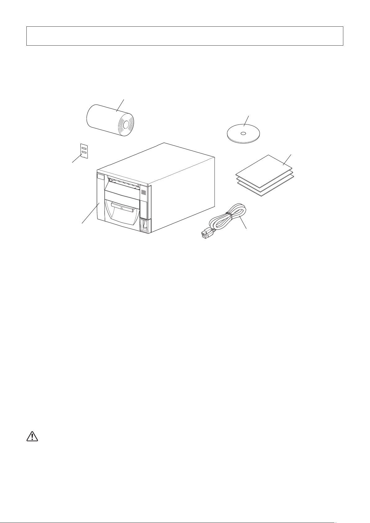
1-1. Unpacking
After unpacking the unit, check that all the necessary accessories are included in the package.
Thermal paper roll
CD-ROM
Switch cover
Setup sheets
Printer
USB cable
1-2. NotesaboutInstallation
1. Place the printer on a rm, level desktop.
2. Do not install the printer where it may become unstable if its front cover were pulled out.
The printer may fall and cause injury.
If you need to install the printer in such a location, x it in place.
3. Do not install the printer where an excessive amount of moisture, dust, oily mist, or iron is present. Doing so may result
in malfunction, re, or electric shock.
4. When placing objects on top of the printer, be sure that the force applied to the printer does not exceed 32.7 N (3 kgf). (Make
sure that the load is not concentrated on the front section of the printer.)
5. Use the printer within boundaries indicated in the environmental requirements. Even when the ambient temperature and
humidity are within the specications, avoid radical changes in environmental conditions.The suitable operating temperature range is as follows:
Operating temperature: 5°C to 45°C
6. This device employs a DC motor and switches that have an electrical contact point.
Avoid using the device in environments where silicon gas can become volatile.
7. When disposing of the printer, obey local regulations.
WARNING
l Shut down your equipment immediately if it produces smoke, a strange odor, or unusual noise. Immediately unplug the
equipment and contact your dealer for advice.
l Never attempt to repair this product yourself. Improper repair work can be dangerous.
l Never disassemble or modify this product. Tampering with this product may result in injury, re, or electric shock.
-
1
-
Page 8
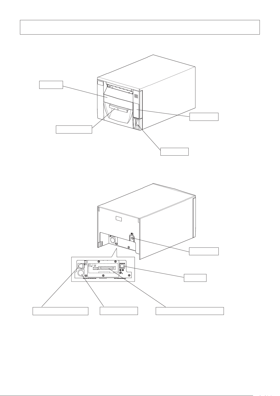
2. Parts Identication and Nomenclature
Front cover
Open to replace paper.
Do not open while printing.
Control panel
Cover open lever
Pull the cover open lever toward
you to open the front cover.
DK
Features LEDs that indicate
printer status and a button for
operating the printer.
Power switch
Turns the printer on
and off.
DC
24V
Speaker jack
Connects to a speaker.
DC
24V
Peripheral drive connector
Connects to peripheral devices
such as cash drawers.
Do not connect this to a telephone
line.
Power connector
Connects to an optional AC
adapter.
-
2
-
USB port
Connects to a host computer
through a USB cable.
Optional interface board connector
If you install an optional interface board, you can connect
the printer to a host computer through a cable.
Page 9
3. Setup
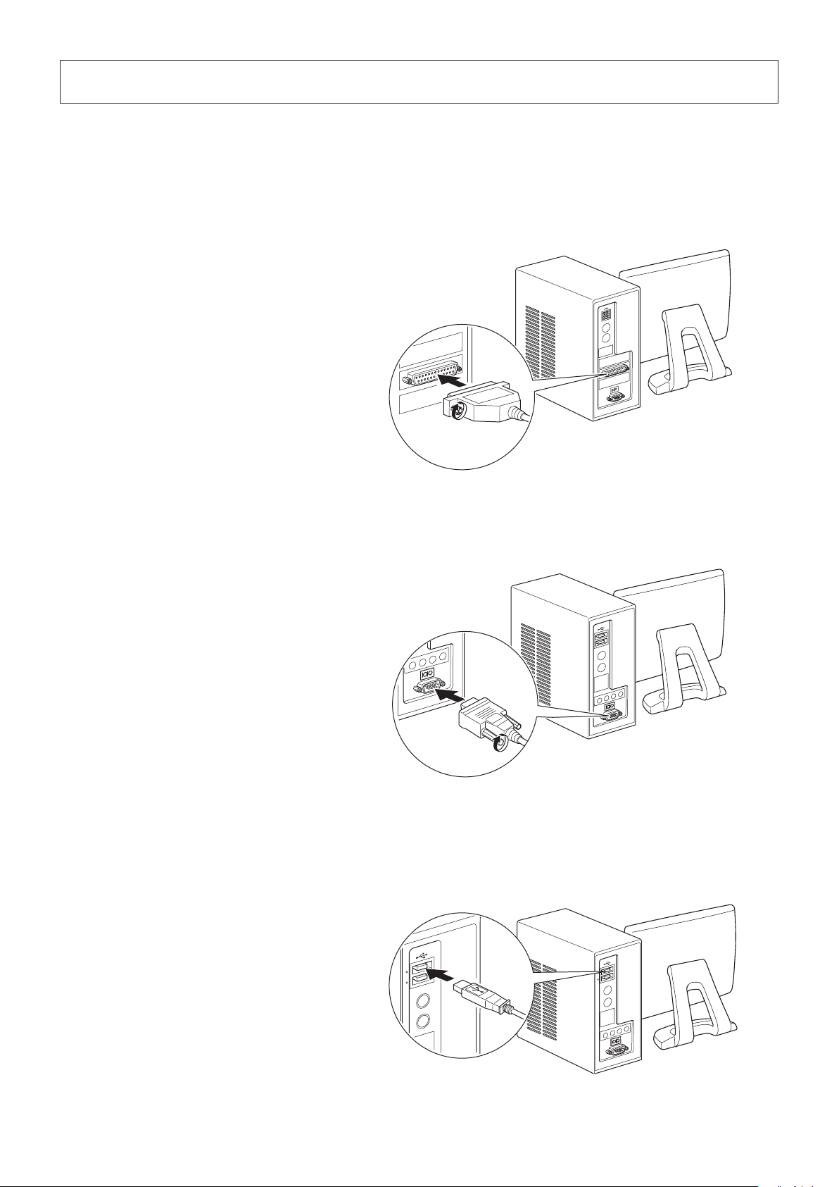
3-1. ConnectingtheInterfaceCabletothePC
3-1-1. ParallelInterfaceCable
Connect the parallel interface cable to a parallel port on your PC.
3-1-2. RS-232CInterfaceCable
Connect the RS-232C interface cable to a RS-232C port on your PC.
3-1-3. USBInterfaceCable
Connect the USB interface cable to a USB port on your PC.
Accessory:USBcable1.8MwithcoreTSP1(P/N:30729170)
-
3
-
Page 10

3-1-4. PoweredUSBInterfaceCable
To protect the printer from electromagnetic interference, afx the ferrite core that came with the optional PoweredUSB in-
terface board to the cable. Then, connect the cable to a PoweredUSB port on your PC.
The optional PoweredUSB cable has been designed specically for this printer.
Note:
Other PoweredUSB cables may not meet the EMC technical standards.
Option:PoweredUSBcable1X8LNL1.2M(P/N:30729130)
Star-recommendedPCIcard:PCIto4PortPoweredUSBCard(Model:301-1150-01;manufacturer:Digi)
3.5 cm
(maximum)
Pull and cut
3-1-5. EthernetInterfaceCable
Connect the Ethernet cable to a USB port on your PC.
-
4
-
Page 11
3-2. ConnectingtheInterfaceCabletothePrinter
Only a USB cable is provided. If you are using another type of cable, obtain a cable that meets the printer specications.
Because the appropriate interface cable differs depending on the system that you are connecting the printer to, contact your
dealer if you are unsure about what cable to use.
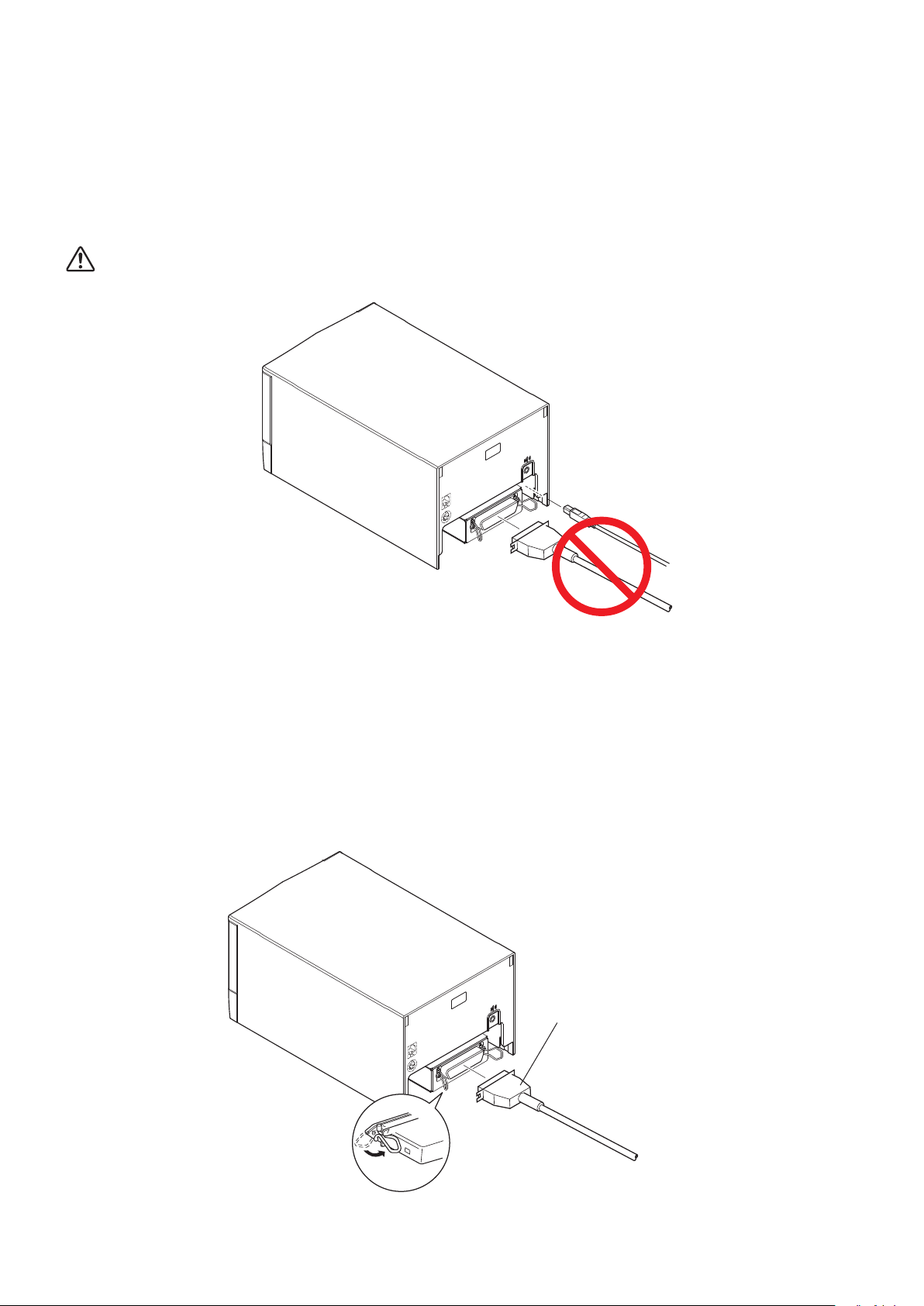
Beforeconnectingordisconnectinganinterfacecable,besuretoremovetheACadapter’spowercableplugfromthe
outlet.
CAUTION:Do not connect move than one at any given time.
3-2-1. ParallelInterfaceCable
You do not have to afx a ferrite core to a parallel interface cable.
To connect a parallel interface cable, follow the instructions given below.
(1) Make sure that the AC adapter’s power cable plug is not connected to the outlet.
(2) Connect the interface cable to the connector on the parallel interface board, and fasten the connector clasps.
Parallel interface cable
-
5
-
Page 12
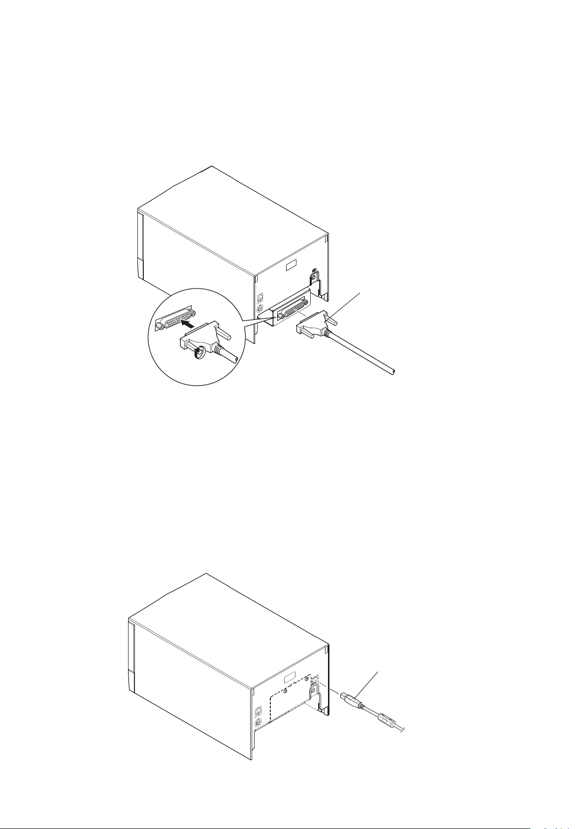
3-2-2. RS-232CInterfaceCable
You do not have to afx a ferrite core to an RS-232C interface cable.
To connect an RS-232C interface cable, follow the instructions given below.
(1) Make sure that the AC adapter’s power cable plug is not connected to the outlet.
(2) Connect the RS-232C interface cable to the connector on the RS-232C interface board, and tighten the left and right con-
nector screws.
RS-232C interface cable
3-2-3. USBInterfaceCable
You do not have to afx a ferrite core to a USB interface cable.
To connect a USB interface cable, follow the instructions given below.
Accessory:USBcable1.8MwithcoreTSP1(P/N:30729170)
(1) Make sure that the AC adapter’s power cable plug is not connected to the outlet.
(2) As shown in the gure, connect the USB interface cable to the USB interface connector.
USB interface cable
-
6
-
Page 13
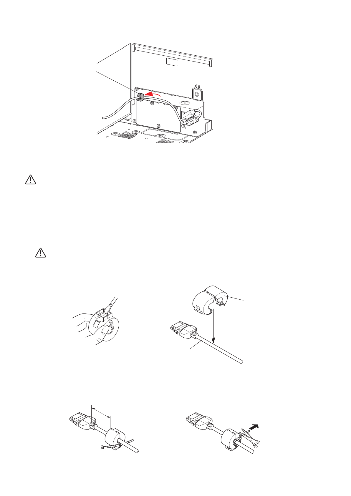
(3) Pass the cable through the cable hook.
Cable hook
DC
24V
3-2-4. PoweredUSBInterfaceCable
CAUTION: The optional PoweredUSB cable has been designed specically for this printer.
Other PoweredUSB cables may not meet the EMC technical standards.
To protect the printer from electromagnetic interference, afx the ferrite core that came with the optional interface board to the
cable. To connect the cable, follow the instructions given below.
(1) Turn the power switch off.
(2) If the AC adapter is connected, remove the power cable plug from the outlet, and then remove the plug from the printer’s
power connector.
CAUTION:Do not connect the AC adapter while the PoweredUSB cable is connected. Doing so may result in mal-
function.
(3) Afx the included ferrite core to the PoweredUSB cable as shown in the gure.
Option:PoweredUSBcable1X8LNL1.2M(P/N:30729130)
Ferrite core
PoweredUSB cable
(4) Pass the fastener through the ferrite core.
(5) Loop the fastener around the PoweredUSB interface cable, and lock it.
Use scissors to cut the excess part of the fastener.
3.5 cm (maximum)
Pull and cut
-
7
-
Page 14
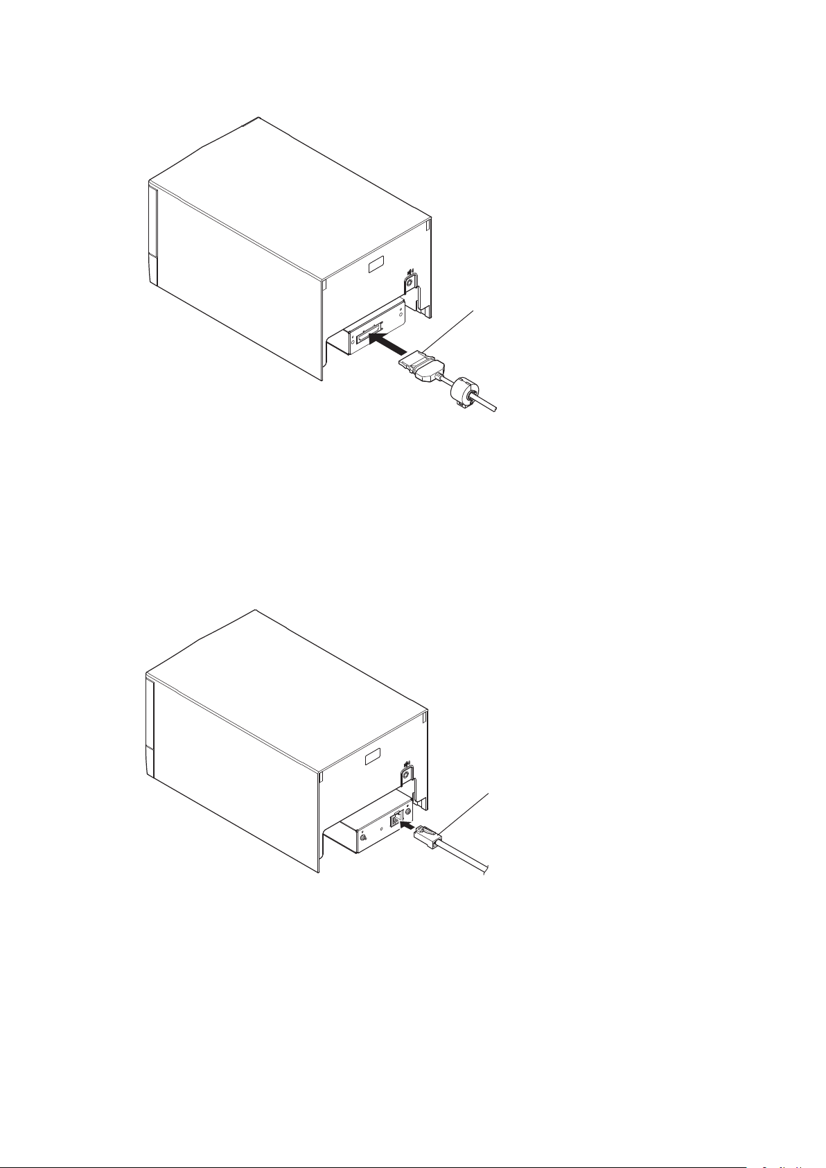
(6) Connect the PoweredUSB interface cable to the connector on the PoweredUSB interface board.
PoweredUSB
interface cable
3-2-5. EthernetInterfaceCable
(1) Make sure that the AC adapter’s power cable plug is not connected to the outlet.
(2) Connect the Ethernet interface cable to the connector on the Ethernet interface board.
Ethernet
interface cable
100/ 10BA SE
SW
g
Link disconnection detection feature
e Ethernet interface model is equipped with a link disconnection detection feature.
If the printer is turned on when an Ethernet cable is not connected to it, the POWER and ERROR lamps are simultane-
ously turned on and o at 2-second intervals to indicate the disconnection.
Be sure to connect the Ethernet cable from a PC or hub to the printer, and then turn the printer on.
-
8
-
Page 15
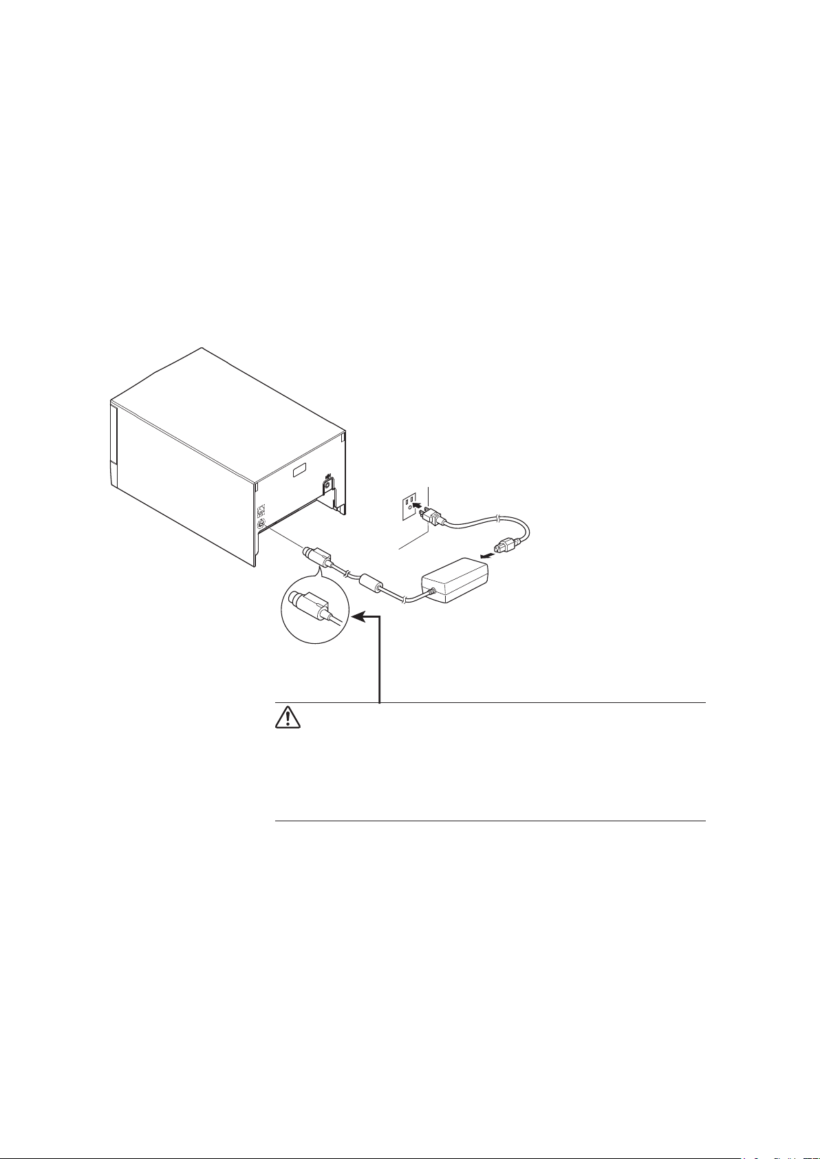
3-3. ConnectingtheACAdapter
Before connecting or disconnecting the AC adapter, make sure that the printer and all the devices connected to it are
Note:
turned off.
Then remove the power cord plug from the outlet.
(1) Connect the AC adapter to the power cable.
Note:The optional AC adapter has been designed specically for this printer.
Other AC adapters may not meet the EMC technical standards.
Option: PS60A-24B1
(2) Connect the AC adapter to the connector on the printer.
(3) Insert the power cable plug into an AC outlet.
CAUTION
When disconnecting the cable, take hold of the cable connector to
pull it out. Releasing the lock makes it easy to disconnect the con-
nector.
Pulling the cable excessively could cause damage to the connector.
-
9
-
Page 16
3-4. TurningthePowerOn
Connect the power cord according to the instructions in section 3-3, “Connecting the AC Adapter”.
Turn on the power switch on the front of the printer.
The POWER lamp on the control panel will light.
Power switch
CAUTION
We recommend that you unplug the printer from the power outlet whenever you do not plan to use it for long periods.
Because of this, you should locate the printer so that the power outlet it is plugged into is nearby and easy to access.
When an Switch blind is afxed to the printer above the power switch, the ON/OFF marks of the power switch may be
hidden. If this occurs, remove the power cord from the outlet to turn the printer OFF.
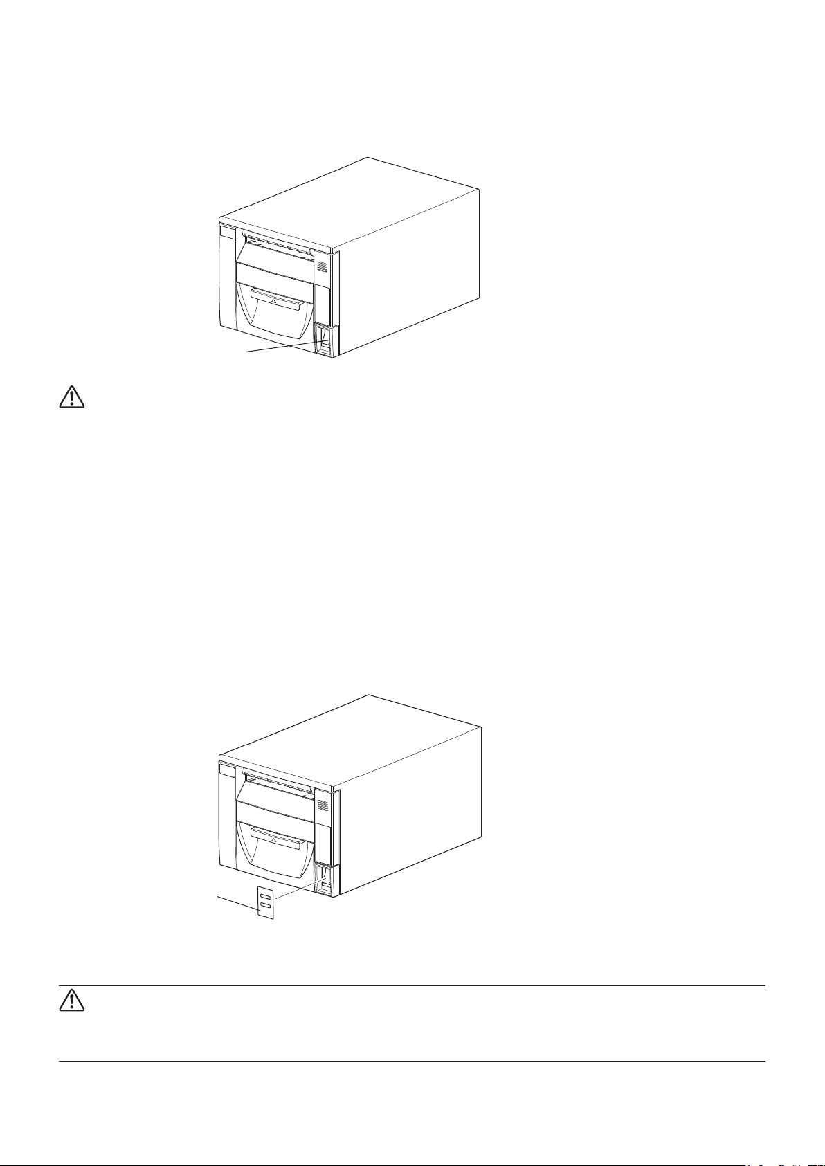
3-5. AttachingtheSwitchCover
You do not have to attach the switch cover. Do so only if you need to.
Attaching the switch cover will:
• Prevent unintentional operation of the power switch.
• Prevent other people from easily operating the power switch.
Attach the switch cover as shown in the gure below.
Switch cover
You can turn the power switch on (I) and off (O) by inserting a ballpoint pen or an object with a pointed tip into the holes in
the switch cover.
CAUTION
We recommend that you unplug the printer from the power outlet whenever you do not plan to use it for long periods.
Because of this, you should locate the printer so that the power outlet it is plugged into is nearby and easy to access.
-
10
-
Page 17
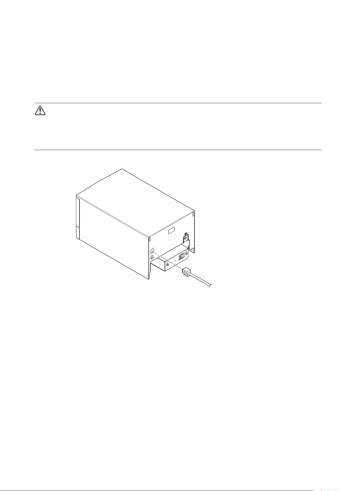
3-6. ConnectingtoaPeripheralDevice
You can connect a peripheral device to the printer using a modular plug.
Follow the instructions given below. For details about the recommended type of modular plug, see chapter 17, “Peripheral
Drive Circuit”.
(1) Make sure that the AC adapter’s power cable plug is not connected to the outlet.
(2) Connect the end of the cable to the peripheral drive connector on the rear panel of the printer.
Connect the other end of the cable to the modular jack of the peripheral device.
CAUTION
Do not connect a telephone line into the peripheral drive connector. Failure to observe this may result in damage
to the printer.
Also, for safety purposes, do not connect wiring to the external drive connector if there is a chance it may carry
peripheral voltage.
100/ 10BA SE
SW
-
11
-
Page 18
3-7. Bluetooth Settings
(For
Bluetooth Interface Models only
)
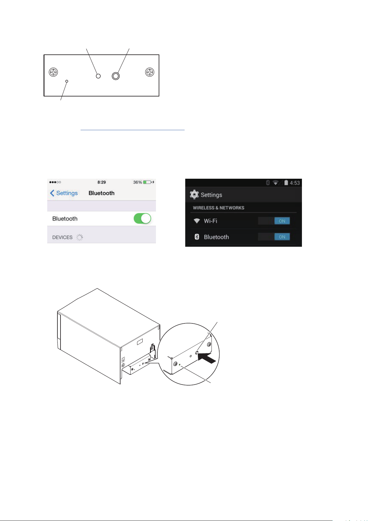
RST button
PAIR button
<
LED> Indicates the status of the Bluetooth interface.
Green (on): Not connected.
Green (ashing): Ready to start pairing.
Blue (on): Connected.
PAIRRST
LED
Purple (ashing): Auto connection ON.
Pair the printer with the master device by following the procedure below.
Compatibility list: http://www.star-m.jp/prjump/000031.html
3-7-1. Pairing using SSP (Simple Secure Pairing) [Default]
(1) Working on the master device, tap [Settings] and set [Bluetooth] to ON.
<
iOS > < Android >
(2) After turning the printer's power switch on, press and hold the PAIR button on the rear interface of the printer for 5 seconds
or more, and then release it. The LED will ash green.
PAIR button
PAIR
RST
Flashing green LED
(3) Pairing will be possible for 60 seconds from when the LED begins ashing green. During this time, execute "Search for
devices" from the master device and tap the relevant device from the displayed list.
Device name: Star Micronics (default)
(4) In an iOS device, after pairing, the LED will automatically begin ashing blue, and the printer will be automatically con-
nected. In an Android device, the LED turns blue only while data is sent.
(5) Connect to the printer from the master device application and perform printing. If the printing is successful, the pairing
process has been completed.
-
12
-
Page 19
Note: e printer performs various processes immediately aer connecting to or disconnecting from a master
device.
Please wait approximately 0.1 seconds aer connecting, and approximately 0.5 seconds aer disconnecting,
before beginning communications with the printer.
3-7-2. Pairing using PIN code
Enter the following information in the master device if it does not support SSP, or when otherwise necessary.
PIN: 1234 (default)
Device name: Star Micronics (default)
It is recommended that you change the PIN code for greater security.
For details regard changing the PIN code, please see the “Software Manual -Star Bluetooth Utility- ”.
3-7-3. Auto Connection Function (iOS only)
Each time the wireless connection is disconnected while communicating with upper-level iOS devices including iPad over
Bluetooth, it is necessary to move back to the Bluetooth setting screen in the upper-level iOS device and tap the desired
printer name again to build a connection. is is an iOS specication.
In order to save this labor, this printer is equipped with the Auto Connection function that automatically requests a con-
nection from an upper-level iOS device that was connected to the printer last time.
e default setting of this function may dier according to the printer model you are using.
Conrm the default settings for your printer, as well as the use examples for ON/OFF settings, and then make the settings
to match your purpose.
You can also check the current ON/OFF setting by performing self-printing.
< Conrmation procedure by self-printing >
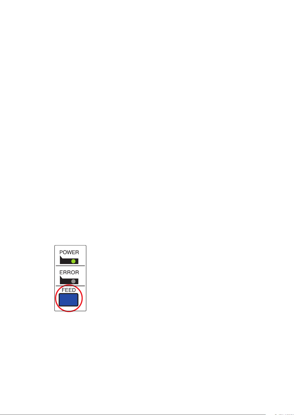
(1) While the printer cover is closed, hold down the FEED button on the
operation panel, and then turn on the power switch.
(2) Self-printing starts and the settings for F/W version, DIP switch,
memory switch, and so on are printed.
Subsequently the interface information is printed and nally the
current ON/OFF settings are printed.
Note: If "Auto Connection function" is set to ON when using devices other than iOS, a Bluetooth communi-
cation with the printer may fail. To use devices other than iOS, such as the Android/Windows devices,
make sure you turn o the "Auto Connection" function before using the printer.
For information on how to set up this function, see "3-7-4. Setting up Auto Connection".
-
13
-
Page 20

See the table below for details of Auto Connection setting.
Auto Connection ON Auto Connection OFF
Reconnecting without changing
the master device
After the printer is turned on, it
automatically connects to the last
master device that was connected.
Changing the connected master
device
Disconnect the Bluetooth connection in such a way as to turn OFF
the power to the upper-level device automatically connected.
Then, establish a pairing with a
desired master device.
Example (recommended) When connecting directly to the
printer from one master device.
After turning on the printer, tap
this printer's name on the Bluetooth settings screen on the master device.
After turning on the printer, establish a pairing with a desired
master device.
When using the printer with multiple master device.
-
14
-
Page 21
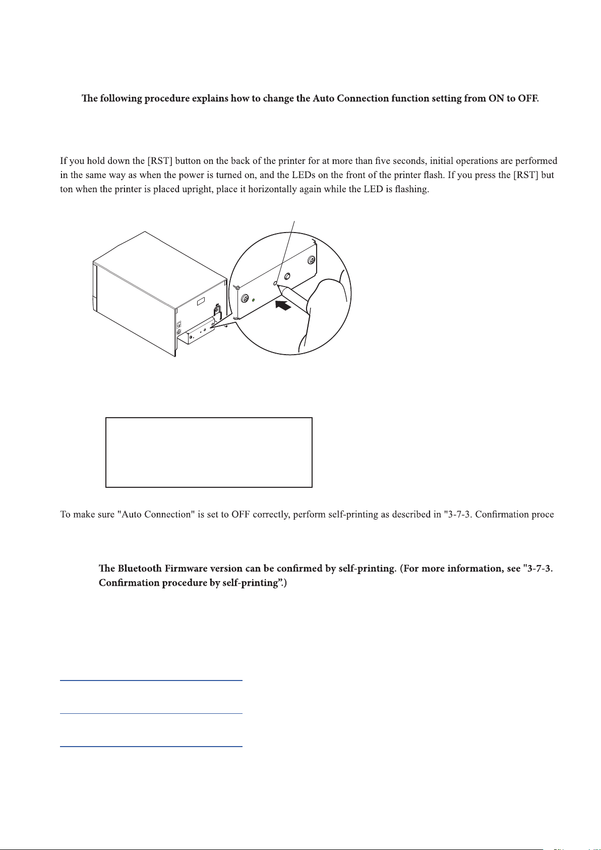
3-7-4. Setting up Auto Connection
Setting up from the Main Unit for the FVP10
Note :
If you want to change it from OFF to ON, please follow the same procedure.
(1) When paper is loaded in the printer and it is turned on, the [POWER] LED(green) on the front of the printer turns
on.
(2)
RST button
PAIR
RST
-
(3) The following information is printed. After that, turn the printer off and then back on again to set "Auto Connec -
tion" to OFF.
< Current Setting >
Auto Connection : OFF
To enable this setting, turn
Printer Power OFF and turn ON.
(4) -
dure by self-printing”.
Note : Only Bluetooth Firmware Version 2.0 or later allows you to switch ON/OFF by pushing the [RST] button.
Setting from the Software
After pairing your device and the FVP10, change "Auto Connection" in the following application provided by our company.
iOS: Download "Star Setting Utility" from the following Web site.
http://www.star-m.jp/prjump/000003.html
Android: Download "Star Setting Utility" from the following Web site.
http://www.star-m.jp/prjump/000004.html
Windows: Download "Star Bluetooth Utility" from the following Web site.
http://www.star-m.jp/prjump/000006.html
-
15
-
Page 22

3-7-5. Resetting Bluetooth Settings
The following procedure explains how to initialize settings that you have changed such as the PIN code, device name, and so on.
(1) While inserting a thin object such as the tip of a pen and holding down the RST button on the rear of the printer, turn on
the printer's power switch. The POWER LED (green) and the ERROR LED (red) on the front of the printer start ashing.
(2) Hold down the RSTbuttonfor4secondsormore (note 1), and then release it.
RST button
PAIR
RST
Hold down for 4 seconds or more
(3) After you release the RST button, if the LED stops ashing and the POWER LED remains lit green within 12 seconds,
initialization is complete. If the LED continues to ash for longer than 12 seconds after releasing the RST button, this indi-
cates that initialization was not successful. Turn off the printer's power and then try again from step 1.
(4) Turn off the printer's power switch and delete the pairing setup with the master device.
Note 1: In step 2, if you do not hold down the RST button for long enough, initialization will not complete correctly.
For F/W Ver2.0, Ver3.0a, and Ver3.0b interfaces
In step 2, you need to hold down the RST button for 8 seconds or more.
Also, aer nishing steps 1 to 3, to check that initialization was completed correctly, perform self-
printing. If the second sheet (*** Bluetooth Information ***) is not printed, initialization has not been
completed correctly. If this happens, turn o the printer's power, and then try again from step 1.
(You can check the rmware version from the self-printing results. See page 13 for the self-printing
procedure.)
2: Do not turn o the printer during initialization; otherwise initialization will not complete correctly.
3: If initialization is not completed correctly, turn o the printer's power and then try again from step 1.
-
16 --
Page 23

4. Loading Paper and Conguring the Cutter
4-1. LoadingaPaperRoll
Use a paper roll that complies with the printer specications. (See chapter 5, “Consumable Parts and AC Adapter”.)
(1) Pull the cover open lever toward you, and pull the front cover out to open it.
Cover open lever
Front cover
(2) Load the paper roll into the printer in the direction indicated by the gure, and pull the leading edge of the paper straight
toward you.
CAUTION1: Pull the paper out while keeping it tight.
2: Be careful not to pull the paper out at an angle, because doing so may cause the paper to jam or skew.
(3) Push the front of the printer to securely close the front cover.
CAUTION1: Be careful not to get your ngers caught when closing the printer’s front cover.
2:
Do not open the front cover until the initial operations are complete.
After the front cover is closed, the printer performs the initial operations (paper feeding to paper cutting).
Paper roll
17
-
Page 24

4-2. ChangingthePaperWidth
Move the paper guide to match the paper roll width.
* The following instructions are for changing the paper width from 79.5 mm to 57.5 mm.
(1) Pull the cover open lever toward you, and pull the front cover out to open it.
Paper guide
Cover open lever
(2) Move the lock lever to the free position.
(3) Turn the knob clockwise until it stops. Move the lock lever to the lock position.
Knob
Lock lever
Lock position
Do not change the paper width while the printer is in use.
Note:
Free position
-
18
-
Page 25

4-3. ChangingthePaperThickness
To change the paper thickness setting, change the tension and the slide lever positions.
4-3-1. SettingtheTensionLeverPosition
By factory default, the tension lever is set for paper thicknesses between 65 µm and 100 µm.
To use paper whose thickness is greater than 100 µm and up to 150 µm, change the left and right paper guides’ tension
lever positions according to the instructions given below.
(1) Pull the cover open lever toward you, and pull the front cover out to open it.
(2) Insert a precision at-blade screwdriver between the front frame and the paper guide, and as shown in the gure, push the
part of the tension lever that is set in the paper guide outward to release it, and turn the lever clockwise.
Tension lever
Front frame
Position for paper whose thickness is between 65 µm and 100 µm
Left paper guide
Right paper guide
Position for paper whose thickness is
greater than 100 µm and up to 150 µm
-
19
-
Page 26

4-3-2. SettingtheSlideLeverPosition
By factory default, the tension lever is set for paper thicknesses between 65 µm and 100 µm.
To use paper whose thickness is greater than 100 µm and up to 150 µm, change the slide lever position according to the in-
structions given below.
(1) Pull the cover open lever toward you, and pull the front cover out to open it.
(2) While pushing the slide lever that is on the left side of the case inward, change the lever position.
Position for paper whose thickness is between 65 µm and 100 µm
2
112
Slide lever
Position for paper thicknesses greater than 100 µm and up to 150 µm
2
2
1
-
20
-
Page 27

4-4. ChangingtheCutterMode
To change the cutter mode from partial to full, follow the instructions given below.
Tochangethecuttermode,changeDipswitchDIPSW1-10(seechapter12,“DipSwitchSettings”).
(1) Pull the cover open lever toward you, and pull the front cover out to open it.
Screw
AC paper guide
Fixed blade
(2) Loosen the two screws at the xed blade section.
To keep the screws from falling, only turn them once or twice.
Note:
(3) Move the xed blade lever in the direction of the arrow until it stops.
Loosen the screw
Fixed blade
(4) Tighten the two screws.
(5) Loosen the screw on either side of the AC paper guide section.
To keep the screws from falling, only turn them once or twice.
Note:
(6) Lower the AC paper guide until it stops. Then, tighten the two screws.
AC paper guide
Loosen the screw
Fixed blade lever
Screw
Do not change the cutter mode while the printer is in use.
Note:
-
21
-
Page 28

4-5. Setup Precautions
Caution Symbol
ese symbols are located near the thermal print head.
Because the thermal print head is hot immediately aer printing, do not touch it. Static
electricity can damage the thermal print head. To protect the thermal print head from static
electricity, do not touch it.
is symbol is located near the cutter.
Never touch the cutter blade, as you could injure your ngers.
is symbol is located near the peripheral drive connector.
Do not connect this to a telephone.
is symbol is located near the screws securing the case or the protective plate, which
should not be opened by individuals other than service personnel. Individuals, other than
service personnel, should not remove these screws. High voltage areas in the case can be
dangerous.
WARNING
l
If you notice smoke or strange odors coming from this product, turn the power switch o immediately, and re-
move the power cord from the AC outlet. For repairs, contact the dealer that you bought the product from.
l
Never attempt to repair the product yourself. Doing so can be dangerous.
l
Never disassemble or modify the product. Doing so may result in injury, re, or electric shock.
l
On models that have cutters or tear bars, do not touch the cutter blade or the tear bar.
- ere is a cutter or tear bar inside the paper outlet slot. Never put your hand in the slot regardless of whether or
not the printer is in operation.
- You must open the printer cover to replace paper. However, because the cutter blade or tear bar is located inside
of the cover, be careful not to bring your face and hands too close to the blade or tear bar when the cover is open.
l
During and immediately aer printing, the area around the print head is very hot. Don’t touch it because you
could be burned.
l
Be sure to turn o the printer before performing maintenance on the cutter. Failing to do so is dangerous.
CAUTION
l
We recommend that you unplug the printer from the power outlet whenever you do not plan to use the printer for
long periods.
Because of this, you should locate the printer so that the power outlet it is plugged into is nearby and easy to ac-
cess.
l
If an AC cord set is supplied with the product, the power cord that is included has been specially designed for the
product.
l
Make sure that the printer and the PC are turned o and unplugged from their AC outlets before you make con-
nections.
l
Do not connect a telephone line to the peripheral drive connector, which is used for devices such as cash drawers.
Doing so may cause the printer to malfunction. Also, for safety purposes, do not connect a wire that may carry ex-
cessive voltage to the peripheral drive connector.
-
22
-
Page 29

l
Do not open the printer covers while the printer is printing or cutting.
l
Do not pull out paper when the printer cover is closed.
l
If liquid or foreign objects (such as coins and paper) enter the inside of the printer, turn the power switch
off, disconnect the power cord from the AC outlet, and consult the dealer that you bought the product from.
Continuing to use the printer may lead to a short-circuit, which may cause electric shock or re.
l
e heating element and the driver IC of the thermal print head are easily damaged. Do not touch them with metal
objects, sandpaper, etc.
l
Do not touch the thermal print head heating element. Doing so may make it dirty, which will decrease the printing
quality.
l
Static electricity can damage the driver IC and other components of the thermal print head. Avoid touching it di-
rectly.
l
Do not operate the printer if there is moisture (which has been caused by condensation or another factor) on the
front surface of the head.
l
e printing quality and the thermal print head’s service life cannot be guaranteed if paper other than the recom-
mended paper is used.
In particular, thermal paper containing Na+, K+, or C1- may drastically reduce the service life of the thermal print
head.
We recommend that you use paper with the following maximum ion densities: 500 ppm of Na+, 150 ppm of K+,
and 300 ppm of Cl-.
For details on recommended thermal paper, see the following webpage.
http://www.starmicronics.com/support/
CAUTION
Wireless Communication
l
Do not use the device where using wireless devices is prohibited or may cause interference or danger.
l
e radio waves generated by the device may interfere with the operation of electronic medical devices. If you are
using any electrical medical device, contact its manufacturer for the restrictions on the use of the device.
l
Security functionality for Bluetooth is installed in this product. Congure the security settings according to the
manual (available on the Star Micronics website) to reduce the risk of security issues.
l
is device supports Bluetooth.
Since this functionality may be limited by local regulations, rst review the radio laws specic to the country in
which the product will be used.
l
Below is a list of laws this device has been approved by. As Star Micronics is committed to constant innovation, re-
visions may be made without an announcement. Access the Star Micronics website for the latest listing of approv-
als.
l
Please refer to Star Micronics website for the latest information and manuals.
-
23 --
Page 30

5. Consumable Parts and AC Adapter
Use paper that meets the specications.
5-1. GeneralThermalPaperRoll
5-1-1. PaperRollSpecications
(1) Paper thickness: 65 µm to 150 µm (excluding Mitsubishi HiTec F5041)
(2) Paper width: 79.5 ± 0.5 mm
57.5 ± 0.5 mm
Note:Never change the paper width while the printer is in use.
(3) Outer roll diameter: ø83 mm or less
Take up paper roll width: 80
(4) Core inner and outer diameters:
65 µm to 75 µm: core inner ø12 ± 1 mm, core outer ø18 ± 1 mm
core inner ø25.4 ± 1 mm, core outer ø32 ± 1 mm
75 µm to 150 µm: core inner ø25.4 ± 1 mm, core outer ø32 ± 1 mm
(5) Printed surface: Outer edge of roll *Donotuseinner-wrappedpaperrolls.
Note1: Do not glue or tape the paper roll and shaft core together.
2: Do not fold the tail end of the paper.
3: We do not recommend the use of paper that has black marks printed on its near-end-sensor side, because near-end
sensing may fail when the near-end sensor deteriorates.
+0.5
mm or 58
- 1
+0.5
- 1
mm
24
-
Page 31

5-1-2. EffectivePrintWidth
Paperwidth
(mm)
Leftandrightmargins
(mm)
Effectiveprintwidth
(mm)
Numberofprintcolumns
(12×24font)
79.5 ± 0.5 4 72 48
57.5 ± 0.5 2.75, 3, 3.6 52.5, 52.0, 50.8 35, 34, 33
Left margin Effective print width Right margin
Paper width
5-2. ThermalLabelPaperRoll(Tacklabelpaperandfull-facethermallabelpaper)
5-2-1. PaperRollSpecications
(1) Total paper thickness: 150 µm or less
(2) Paper width: 79.5 ± 0.5 mm
(3) Outer roll diameter: ø83 mm or less
Take up paper roll width: 80
+0.5
mm or 58
- 1
+0.5
- 1
mm
(4) Core inner and outer diameters:
core inner ø25.4 ± 1 mm, core outer ø32 ± 1 mm
(5) Printed surface: Outer edge of roll *Donotuseinner-wrappedpaperrolls.
Note1: Set the tension lever to the position for paper thicknesses greater than 100 µm and up to 150 µm.
2: Set the slide lever to the position for paper thicknesses greater than 100 µm and up to 150 µm.
3: Do not glue or tape the paper roll and shaft core together.
4: Do not fold the tail end of paper.
5: When using tack label paper, be sure to cut the backing paper.
-
25
-
Page 32

5-2-2.
EffectivePrintWidth
Paperwidth
(mm)
Leftandrightmargins
(mm)
Tack label paper 76 ± 0.5 3 70 46
Full-face thermal
label paper
■
DetailedDiagramsofRecommendedTackLabelSpecifications
79.5 ± 0.5 4 72 48
Tack label
ø83 MAX
Effectiveprintwidth
(mm)
Numberofprintcolumns
(12
24font)
×
ø32 ± 1
ø25.4 ± 1
Release paper
(backing paper)
Printing direction
Black mark
(back of diagram)
+0.5
80
- 1.0
(Rolled dimension)
Base material
(label paper)
+1.0
5 ± 1.0
1
0.8
-
30 to 295
(Label length)
15 MIN
35 to 300
(Black mark pitch)
5
Paper tube
(1.75)
76 ± 0.5 (Label width)
1.75 ± 0.5
79.5 ± 0.5 (Backing
paper width)
Unit: mm
-
26
-
Page 33

■
DetailedDiagramofEffectivePrintingArea
3 (bottom margin) 4.5 (top margin)
79.5 ± 0.5 (backing paper width)
76 ± 0.5 (label width)1.75 ± 0.5 (1.75)
* Minimum settable top margin when
paper is fed using back-feed
22.5 to 287.5 (effective print length)
30 to 295 (label length)
35 to 300 (black mark pitch)
3 (left margin) 3 (right margin)Dots 39 to 598
70 (effective print width: 46 columns with font A)
Effective
printing area
Unit: mm
■
DiagramofCutPosition,PrintingLine,andBlackMarkSensorPosition
2.5
2.5
5
Approx. 14 Approx. 13
Cut position
Printing line
Black mark sensor
Unit: mm
5-3. ACAdapter(Option)
Note:The optional AC adapter has been designed specically for this printer.
Other AC adapters may not meet the EMC technical standards. They may also cause damage to the printer, electric
shock, or re.
Model name: PS60A-24B1
Input: 90 to 264 V AC, 50/60 Hz
Output: 24±10% V DC, 2.1 A
-
27
-
Page 34

6. Control Panel and Other Functions
6-1. ControlPanel
(1) POWER lamp (green)
(1) POWER lamp (green)
Lights when the printer is online.
This lamp also indicates errors, in combination with other lamps.
(2) ERROR lamp (red)
(2) ERROR lamp (red)
Lights when the cover is open.
This lamp also indicates errors, in combination with other lamps.
(3) FEED button
(3) FEED button
When the printer is online, pressing this button feeds the paper roll.
When an audio error message is being played, pressing this button stops
the message.
Press this button again if you want to hear the message again.
6-2. Errors
(1) Recoverable errors
Error description POWER ERROR Recovery condition
Thermal head
high temperature detection
error
Paper roll
near-end detection*1
Cover open error On On The printer recovers when you close the cover.
Paper out error On
Black mark error On
Link disconnection detec-
tion
*2
Flashes at 2 second
intervals
On
Flashes at 2 second
intervals
Off The printer recovers automatically when the thermal head cools.
Flashes at 2 second
intervals
Flashes at 0.5 sec-
ond intervals
Flashes at 1 second
intervals
Flashes at 2 second
intervals
Indicates that the paper roll is near the end. The printer recovers when you set a
new paper roll and close the front cover.
The printer recovers when you set a new paper roll and close the front cover.
The printer recovers when you change the black mark paper (readjust in PE and
BM sensor adjustment mode).
Connect an Ethernet cable. For details, see section 3-2-5, "Ethernet Interface
Cable."
*1 Near-end detection does not work until the paper is fed for 100 mm after the cover is opened and then closed.
*2 Ethernet interface model only
Note1: If the cutter cannot return to the home position, or the printer cannot initialize, the error is unrecoverable.
For details, see section 9-3, “Releasing the Cutter Lock”.
2:If the paper is jammed, turn the power off, clear the jammed paper, and then turn the power on.
For details, see section 9-2, “Removing Paper Jams”.
(2) Errors that the printer cannot recover from
Error description POWER ERROR Cause Recovery condition
Cutter error Off Flashes at 0.25 second intervals Cutter failure.
Flash memory error Off Flashes at 0.5 second intervals Flash memory access error.
EEPROM error Off Flashes at 0.75 second intervals EEPROM access error.
SRAM error Off Flashes at 1 second intervals SRAM access error.
Head thermistor error Off Flashes at 1.5 second intervals Head thermistor error has been detected.
Power voltage error Off Flashes at 2 second intervals Power voltage error has been detected.
The printer cannot recover
from this error.
The printer cannot recover
from this error.
The printer cannot recover
from this error.
The printer cannot recover
from this error.
The printer cannot recover
from this error.
The printer cannot recover
from this error.
Note1: If an unrecoverable error occurs, turn the power off immediately.
2: A power voltage error may be a result of a power supply malfunction.
If other unrecoverable errors occur, contact your dealer for repairs.
* When an error occurs, an audio error message is played. For details, see section 8-4, “Audio Error Messages”.
-
28
-
Page 35

6-3. Self-Printing
6-3-1. TestPrinting
(1) Load a paper roll into the printer.
(2) With the front cover closed, turn the power switch on while holding down the FEED button.
(3) The internal speaker produces a buzzer sound, and the printer starts a test print.
The printer prints its version number, DIP switch settings, memory switch settings, etc. When the test print is
nished, the printer returns to normal mode.
6-3-2. HexadecimalDumpMode
(1) With the front cover open, turn the power on while holding down the FEED button.
(2) When you close the front cover after the printer initialization has been completed, the printer prints “*** Hex
Dump Printing ***” and enters Hexadecimal Dump mode.
(3) All the signals received from the host computer are printed in hexadecimal code. You can use this mode to check
whether the control codes sent from your program are being received correctly by the printer.
(4) If the last line of program data is less than one line, you can press the FEED button to print it.
To clear this mode, turn the printer off.
-
29
-
Page 36

6-4. AdjustingSensors
6-4-1. PEandBMSensorAdjustmentMode
(1) Check that the printer is turned off.
(2) Unfasten the screw holding the DIP switch cover at the bottom of the printer, and remove the cover.
(3) Using a pointed object, set DIP switch DIPSW1-4 to OFF and DIP switches DIPSW1-5, DIPSW1-6, and DIPSW1-7 to ON.
DIP switch cover
24V
DC
OFF
ON
1 2 3 4 5 6 7 8 9
DIP-SW 1 DIP-SW 2
10
1 2 3 4
(4) Open the front cover, and set a paper roll into the printer.
(5) Turn the printer on.
The lamps on the control panel will ash, and the printer will enter sensor adjustment mode.
(6) As shown in the gure below, turn VR1 with a precision at-blade screwdriver so that both the POWER lamp (green) and
ERROR lamp (red) light.
VR1 VR2
DC
24V
-
30
-
Page 37

(7) Turn the printer off, and set DIP switches DIPSW1-4, DIPSW1-5, DIPSW1-6, and DIPSW1-7 to their original settings.
(8) Attach the DIP switch cover.
6-4-2. NESensorAdjustmentMode
(1) Check that the printer is turned off.
(2) Open the front cover, remove the paper roll from the printer, and close the front cover.
(3) Unfasten the screw holding the DIP switch cover at the bottom of the printer, and remove the cover.
(4) Using a pointed object, set DIP switches DIPSW1-4 and DIPSW1-5 to OFF and DIP switches DIPSW1-6 and DIPSW1-7
to ON. Then turn the printer on.
The lamps on the control panel will ash, and the printer will enter sensor adjustment mode.
(5) Turn VR2 clockwise all the way with a precision at-blade screwdriver as shown in the gure below.
If the POWER lamp (green) is on at this point, proceed to step (7).
If the POWER lamp (green) is off, proceed to step (6).
DIP switch cover
VR1 VR2
24V
DC
-
31
OFF
ON
1 2 3 4 5 6 7 8 9
DIP-SW 1 DIP-SW 2
-
10
1 2 3 4
Page 38

(6) Turn VR2 so that both the POWER lamp (green) and ERROR lamp (red) light.
VR1 VR2
(7) Press the FEED button. The LED will ash, and the printer will enter sensor check mode.
(8) Open the front cover, set a paper roll into the printer, and close the front cover.
Check that the POWER lamp (green) is lit and the ERROR lamp (red) is off.
(9) Open the front cover, remove the paper roll from the printer, and close the front cover.
Check that both the POWER lamp (green) and ERROR lamp (red) are lit.
(10) Turn the printer off, and set DIP switches DIPSW1-4, DIPSW1-5, DIPSW1-6, and DIPSW1-7 to their original settings.
(11) Attach the DIP switch cover.
-
32
-
Page 39

7. Adjusting the Near-End Sensor
To use the near-end sensor, set the remaining paper length to detect.
Follow the instructions given below.
(1) Open the rear cover.
(2) Use a ballpoint pen or a pointed object to pull the sensor up and move it to the appropriate position.
Check that the position is correct.
2
112
Level 1
2
1
Level 2
2
1
Appropriate positions according to the type of paper
Thickness
(µm)
Core paper roll with ø12 (A) inner diameter and
ø18 (B) outer diameter
Detected diameter
(C; mm)
Remaining paper length
(m)
Core paper roll with ø25.4 (A) inner diameter and ø32 (B)
outer diameter
Detected diameter (C; mm) Remaining paper length (m)
Level 1 Level 2 Level 1 Level 2 Level 1 Level 2 Level 1 Level 2
65
Approx. ø23 Approx. ø26
75 Approx. 2.1 Approx. 3.7 Approx. 4.4 Approx. 7.7
80
95
150
C
Approx. 2.5 Approx. 4.3
B
Approx. ø38
─ ─
─ ─
─ ─
Approx. ø42
Approx. 5.1 Approx. 8.9
Approx. 7.3
Approx. 6.1
Approx. 3.9
A
C
Note:
Paper roll core
1) The adjuster is factory set to level 1.
2) The detected diameter and remaining paper length given in the table are calculated values; there may be discrepancies de-
pending on the rolled state of the paper, the actual mechanism, and the printing pattern.
3) With thick paper (whose thickness is greater than 75 µm) or label paper, the paper roll itself may become loose, causing
errors in detection. So set the adjuster to level 2.
-
33
-
Page 40

8. Speaker
8-1. SpeakerSpecications
(1) Model number: SCG-16A
(2) External dimensions: ø16-h3
(3) Sound pressure: By itself 92.5 dB ± 3 dB (rated input: 0.3 W, measurement distance: 10 cm)
Embedded in printer 61.2 dB ± 3 dB (measurement distance: ISO7779 compliant; diagonally up-
wards from the printer at a distance of 67.5 cm)
8-2. AdjustingtheVolume
To adjust the volume, follow the instructions given below.
(1) Unfasten the screw holding the DIP switch cover at the bottom of the printer, and remove the cover.
(2) Turn the volume adjuster with a precision at-blade screwdriver to adjust the volume.
Speaker jack
Volume adjuster
+ direction to increase
– direction to decrease
DIP switch cover
24V
DC
8-3. SpeakerJack
(1) Connector: ø3.5 monaural mini jack
(2) Target speaker: A speaker with an impedance of 8 Ω is recommended.
-
34
-
Page 41

8-4. AudioErrorMessages
When an error occurs, the printer produces an audio error message.
Status AudioMessage
On-Line Warning output Paper roll near-end detection*1
Error
Auto recovery error
Thermal head high temperature
detection error
Cover open error*2
Errors that can be
recovered from
Paper out error
Black mark error
Cutter error
Flash error
Errors that cannot be
recovered from
EEPROM error
SRAM error
Head thermistor error
Power voltage error
Paper Near End, please prepare for the paper rell.
Head Temperature is too high, please wait until Power lamp
turns on.
Please close the printer cover.
Paper end. Please rell paper.
Black Mark error is detected.
Please conrm the specication according to the Users Manual.
Cutter error.
Please refer to the Users Manual for recovery.
Flash ROM error. Please turn off the printer and refer to the Users Manual for recovery.
EEPROM error. Please turn off the printer and refer to the Us-
ers Manual for recovery.
SRAM error. Please turn off the printer and refer to the Users
Manual for recovery.
Thermistor error. Please turn off the printer and refer to the Us-
ers Manual for recovery.
Power Voltage error. Please turn off the printer and refer to the
Users Manual for recovery.
*1 Near-end detection does not work until the paper is fed for 100 mm after the cover is opened and then closed.
*2 Output 5 seconds after a cover open error occurs.
-
35
-
Page 42

9. Preventing and Removing Paper Jams
9-1. PreventingPaperJams
When you set the paper roll into the printer, do not pull out the end of the paper at an angle.
Do not touch the paper roll when the printer is printing or paper-feeding or before the cut operation has nished completely.
Holding or pulling the paper while it is being fed may cause paper jams, improper cutting, or improper line breaks.
9-2. RemovingPaperJams
If a paper jam occurs, remove the paper according to the instructions given below.
(1) Turn the power switch off.
(2) Pull the cover open lever toward you to open the front cover.
(3) Remove the jammed paper.
CAUTION: Do not pull on the paper with the printer cover closed. Doing so may cause damage to or deformation
of parts such as the thermal head and the rubber roller.
(4) Set the paper roll straight, and gently close the front cover.
CAUTION1: Set the paper roll straight.
If you close the front cover with the paper roll skewed, paper jams may occur.
2: Close the front cover completely.
If the front cover is not closed completely, the printer may not print.
(5) Turn the power switch on.
Make sure that the ERROR lamp is not lit.
CAUTION: When the ERROR lamp is lit, the printer will not accept any commands. Be sure to close the front cover
completely.
9-3. ReleasingtheCutterLock
If the cutter locks, release it according to the instructions given below.
CAUTION:
(1) Turn the power switch off.
(2) Close the front cover, and turn the printer back on. In ordinary cases, this will release the lock.
Ifthelockisnotreleased,contactyourdealer.
Be sure to turn off the printer rst when maintenancing the cutter.
-
36
-
Page 43

10. Maintenance
Accumulation of paper dust and dirt may cause the printer to not print portions of characters.
To prevent such problems, perform periodic maintenance, such as removing paper dust from the paper transport section and removing
the blackened paper dust from the thermal head surface.
Note:Turn the printer’s power switch off before performing maintenance.
Use the following as a guideline for when to periodically clean the printer.
Thermal paper: Every six months or 1,000,000 lines of printing
Label paper: Every month or 200,000 lines of printing
10-1. ThermalHead
To remove the blackened paper dust that has accumulated on the thermal head surface, wipe it clean with a cotton swab (or soft
cloth) dipped in alcohol (ethanol, methanol, or isopropyl).
The thermal head is located where it is hard to look at directly. Use the mirror sheet to clean the head.
CAUTION
Thermal head
Mirror sheet
1: The thermal head is easily damaged, so clean it with a soft cloth, taking care not to scratch it.
2: Do not clean the thermal head immediately after printing, when it is hot.
3: Be careful of static electricity while cleaning the thermal head. Static electricity can damage the
head.
4: When label paper is used, paste adheres to the head, platen, and paper guides. Wipe off the
paste. If you don’t, paper transport problems and improper printing may occur. We recommend
that you wipe off the paste frequently, not just during periodic maintenance.
5: Turn the power on only after the alcohol has dried completely.
-
37
-
Page 44

10-2. PlatenRubberRoller
Apply alcohol (ethanol, methanol, or isopropyl) to a dry, soft cloth, and wipe off the dirt from the rubber roller. Clean the entire
rubber roller by rotating it.
Paper holder
Rubber roller
10-3. PaperHolder
Clean the paper holder of debris, dust, paper particles, glue, etc. that may have accumulated.
10-4. SensorsandTheirSurroundingArea
Clean the sensors of debris, dust, paper particles, etc.
In particular, if the reection sensors are dirty, detection will not be performed properly.
Cleaning is relatively easy if you use a brush or a similar tool.
PE and BM sensor
-
38
-
Page 45

11. Specications
11-1. GeneralSpecications
(1) Print method: Direct line thermal printing (thermal type)
(2) Print speed: Max. 2000 dots/sec. (250 mm/sec.; standard monochrome mode)
(3) Dot density: 203 dpi; 8 dots/mm (0.125 mm/dot)
(4) Printing width: Max. 72 mm
Settable between 30 mm and 72 mm at 1 mm intervals
(5) Number of print columns: Max. 48 columns (12 × 24 font)
Max. 64 columns (9 × 24 font)
Max. 36 columns (16 × 24)
Max. 24 columns (24 × 24 kanji font)
(6) Paper feed method: Friction feed
Feed pitch 0.125 mm
(7) Paper roll: See section 5-1, “General Thermal Paper Roll” and 5-2, “Thermal Label Paper Roll” in chapter 5,
“Consumable Parts and AC Adapter”.
Paper width:
General thermal paper: 79.5 ± 0.5, 57.5 ± 0.5 mm
Label paper: 79.5 ± 0.5 mm (backing paper width)
Roll diameter: Max. ø83 mm
(8) External dimensions: 144 mm (width) × 227.7 mm (depth) × 114 mm (height)
144 mm (width) × 316.2 mm (depth) × 114 mm (height); with cable cover attached
* Front section height is 115.5 mm.
(9) Weight: 2.8 kg (without paper roll)
(10) Noise: Approx. 53 dB
227.7
144
-
39
114
Unit: mm
-
Page 46

11-2. AutoCutterSpecications
DC
24V
DK
(1) Cutting method: Guillotine type
(2) Cutter modes: Switchable between full cut and partial cut (leaves one uncut portion in center of paper)
(For instruction on how to switch the mode, see section 4-4, “Changing the Cutter Mode”.
(3) Cutting duty cycle: Min. 3 seconds/cut
(4) Paper thickness: 65 µm to 150 µm
11-3. InterfaceSpecications
USB standard: Type-B
Options
Parallel: 36-pin Amphenol
IEEE1284 compliant (Compatibility and Nibble modes)
Serial RS-232C: D-SUB 25 pin
Ethernet: RJ-45
PoweredUSB: FCI 69913-104LF (1 x 8 right-angle type)
11-4. PowerSupplySpecications
(1) Operating voltage: 24 V DC ± 10%
(2) Current consumption (24 V DC, room temperature):
Standby Approx. 0.12 A
ASCII printing Approx. average 1.56 A
100% duty cycle printing Approx. peak 7.84 A
(Solid printing) Approx. average 4.2 A
Note:Continuous solid printing should be 10 seconds or less.
(3) Power connector pinout:
Pin number Function
1 +24 V
2 GND
3 N.C
Shell Frame ground
Note: The optional AC adapter (PS60A-24B1) has been designed specically for this printer.
Other AC adapters may not meet the EMC technical standards.
1
3
2
Power connector
If you are preparing your own power supply, without using the optional AC adapter, note the following points.
• Use a power supply that is rated 24 V DC and 2.1 A, or equivalent.
(Select a power supply with current capacity that is appropriate for the actual printing ratio.)
• Use a power supply that complies with SELV output or LPS (Limited Power Source).
• Take into consideration the noise in the environment that the printer is installed in, and take appropriate mea-
sures to protect the printer from static electricity, AC line noise, etc.
-
40
-
Page 47

11-5. EnvironmentalRequirements
Temperature and humidity
(1) During operation
Temperature: 5°C to 45°C
Humidity: 10% RH to 90% RH (no condensation)
(%RH)
90
80
60
Relative humidity
40
20
10
0 10 20 30 40 50
(2) During storage (excluding paper)
Temperature: -20°C to 60°C
C
34°
90% RH
Operating environment
Temperature (°C)
Operating temperature and humidity range
40°
C
65% RH
C
45°
50% RH
Humidity: 10% RH to 90% RH (no condensation)
Note: The maximum temperature and humidity combination is 40°C and 90% RH (without condensation).
11-6. ReliabilitySpecications
(1) Service life Mechanical: 20,000,000 lines
Head: 150 km, 150,000,000 dots (maximum for monochrome printing)
<Conditions>
Average printing ratio: 12.5%; recommended thermal paper: 65 µm (when using P220AG)
(2) MCBF: 60,000,000 lines
The Mean Cycle Between Failure (MCBF) is dened to be the overall failure cycle, which includes random or wear fail-
ures that occur until the printer reaches its mechanical life of 20,000,000 lines.
Note: The mechanical life is 20,000,000 lines. The MCBF of 60,000,000 lines does not indicate the durable service life.
(3) Auto cutter service life
l
Paper width of 79.5 mm and 57.5 mm including tack label backing paper
Paper width between 65 µm and 100 µm: 2,000,000 partial cuts, 2,000,000 full cuts
Paper width greater than 100 µm and up to 150 µm: 600,000 partial cuts, 600,000 full cuts
l Paper width of 79.5 mm for full-face thermal label paper
300,000 partial cuts and 300,000 full cuts
Note:All the reliability values indicated above are based on the use of the recommended thermal paper. They are not guar-
anteed with the use of non-recommended thermal paper.
-
41
-
Page 48

11-7. BlackMarkSpecications
Note:
Back side
mm
0.8
1
–
+
1
Print direction
Top margin: 14 mm or more
of paper
2.5 mm
Cut position
Length A: 30 to 300 mm
5±1 mm
Print area
The side for
printing is the
front side of
paper.
15 mm or more
Bottom margin
3 mm + length A × 3% or more
1) The cut position shown above is for when memory switch #2 (print start position adjustment) is set to its default setting.
2) The black mark’s PCS value must be 0.90 or more.
3) With the factory default setting, the printer may not detect black marks correctly, depending on the paper that you are
using and the printed condition of the black marks.
We recommend that you make adjustments with the paper that you are using.
4) The accuracy of paper feeding to the start position through black mark detection is ±2 mm of the reference print posi-
tion. The printing length accuracy is ±2% of the set value, taking into account the environmental temperature and the
error in the manufacturing process of the platen core. Add a maximum of -5% error to the set value when taking the ser-
vice life into account. If you are using pre-printed paper, pay attention to the print layout.
5) The printing area is as shown in the above diagram when you use black marks.
The top margin consists of approximately 13 mm from the print position to the cut position (auto cutter) and at least
1 mm (8 dot lines) of paper feeding when printing after cut operations. Therefore, the minimum total margin is 14 mm.
Ensure that the margin shown in the above diagram is used to prevent the printing length setting along the paper feed
direction from exceeding the black mark pitch. Otherwise, pages may be skipped.
[Example of printing area setting]
<When the black mark pitch (length A) is 100 mm>
Top margin: 14 mm/Bottom margin: 3 mm + (100 mm × 0.03) = 6 mm
Therefore, the printing length along the paper feed direction must be 80 mm or less.
-
42
-
Page 49

12. DIP Switch Settings
Two DIP switches are provided at the bottom of the printer, and you can set them according to the tables that start on the next
page.
To change the settings, follow the instructions given below.
(1) Check that the printer is turned off.
(2) Unfasten the screw holding the DIP switch cover at the bottom of the printer, and remove the cover.
DIP switch cover
OFF
ON
1 2 3 4 5 6 7 8 9
DIP-SW 1 DIP-SW 2
10
1 2 3 4
24V
DC
(3) Using a pointed object, set the DIP switches.
(4) Attach the DIP switch cover, and fasten it with screws.
Note:The new settings take effect when you turn on the printer.
-
43
-
Page 50

12-1. ParallelInterfaceModel
DIP-SW 1
■
DIP-SW1
Switch Function ON OFF
1-1 Emulation STAR line mode ESC/POS mode
1-2
1-3 Reserved Always ON
1-4 Sensor adjustment Invalid Valid
1-5 Reset using the INIT signal (pin #31) Valid Invalid
1-6
STAR line mode
ESC/POS mode
Handshaking conditions
(conditions for BUSY)
Reserved
Resolution correction
Always ON
203 dpi 180 dpi
Receive buffer full or
ofine
DIP-SW 2
Receive buffer full
1-7 ASB function*1 Invalid Valid
1-8
1-9 Low peak current mode Invalid Valid
1-10 Installed cutter type Partial cut Full cut
*1 ASB function:
Automatically sends a status signal to the host whenever the printer status changes (cover open, paper out, error, etc.).
For details, see the separate command specications (Star Line mode and ESC/POS mode).
*2 NSB function:
Automatically sends a status signal whenever the printer switches to reverse transfer mode.
For details, see the separate command specications (Star Line mode).
■
DIP-SW2
Switch Function ON OFF
2-1 to 2-4
By factory default, all settings are set to ON.
STAR line mode NSB function*2 Invalid Valid
ESC/POS mode Reserved Always ON
– – –
-
44
-
Page 51

12-2. RS-232CInterfaceModel
DIP-SW 1
■
DIP-SW1
Switch Function ON OFF
1-1 Emulation STAR line mode ESC/POS mode
1-2
1-3 Reserved Always ON
1-4 Sensor adjustment Invalid Valid
1-5 Reserved Always ON
1-6
1-7 ASB function*1 Invalid Valid
STAR line mode
ESC/POS mode
Handshaking conditions
(conditions for BUSY)
Reserved
Resolution correction
Always ON
203 dpi 180 dpi
Receive buffer full or
ofine
DIP-SW 2
Receive buffer full
1-8 Reserved Always ON
1-9 Low peak current mode Invalid Valid
1-10 Installed cutter type Partial cut Full cut
*1 ASB function:
Automatically sends a status signal to the host whenever the printer status changes (cover open, paper out, error, etc.).
For details, see the separate command specications (Star Line mode and ESC/POS mode).
■
DIP-SW2
Switch Function ON OFF
2-1 to 2-4
By factory default, all settings are set to ON.
– – –
-
45
-
Page 52

To change DIP-SW 3, which is on the RS-232C interface PCB, follow the instructions given below.
(1) Check that both the printer and the host computer are turned off.
(2) Remove the interface board from the printer.
RS-232C interface board
DC
24V
(3) Remove the interface PCB from the interface board so that you can access DIP-SW 3.
(4) Change the DIP-SW 3 settings.
RS-232C interface PCB
DIP-SW 3
(5) Attach the RS-232C interface PCB following the procedure for removing it in reverse.
(6) Install the interface board onto the printer.
(7) Turn both the printer and the host computer on.
Note: The new settings take effect when you turn on the printer.
■
DIP-SW3
Switch Function ON OFF
3-1
3-2
Baud rate See the table below.
3-3 Data length 8 bits 7 bits
3-4 Parity check Invalid Valid
3-5 Parity Odd Even
3-6 Handshaking DTR XON/XOFF
3-7
3-8
Reserved Always OFF
Baud rate settings
3-1 3-2 Baud rate
ON ON 9600 bps
OFF ON 4800 bps
ON OFF 19200 bps
OFF OFF 38400 bps
By factory default, 3-7 and 3-8 are OFF, and all other settings are ON.
-
46
-
Page 53

12-3. USBandPoweredUSBInterfaceModel
DIP-SW 1
■
DIP-SW1
Switch Function ON OFF
1-1 Emulation STAR line mode ESC/POS mode
1-2
1-3 Reserved Always ON
1-4 Sensor adjustment Invalid Valid
1-5 USB mode Printer Class Vendor Class
1-6
1-7 ASB function*1
1-8
STAR line mode
ESC/POS mode Resolution correction 203 dpi 180 dpi
Handshaking conditions
(conditions for BUSY)
STAR line mode
ESC/POS mode Reserved Always ON
Reserved
Printer Class Valid Invalid
Vendor Class Invalid Valid
Printer
NSB
function*2
Class
Vendor
Class
Always ON
Receive buffer full or
ofine
Valid Invalid
Invalid Valid
DIP-SW 2
Receive buffer full
1-9 Low peak current mode Invalid Valid
1-10 Installed cutter type Partial cut Full cut
*1 ASB function:
Automatically sends a status signal to the host whenever the printer status changes (cover open, paper out, error, etc.).
For details, see the separate command specications (Star Line mode and ESC/POS mode).
*2 NSB function:
Automatically sends a status signal whenever the printer switches to reverse transfer mode.
For details, see the separate command specications (Star Line mode).
■
DIP-SW2
Switch Function ON OFF
2-1 to 2-4
By factory default, all settings are set to ON.
–
Always ON
-
47
-
Page 54

12-4. EthernetInterfaceModel
DIP-SW 1
■
DIP-SW1
Switch Function ON OFF
1-1 Emulation STAR line mode ESC/POS mode
1-2
1-3 Reserved Always ON
1-4 Sensor adjustment Invalid Valid
1-5 Reset using the INIT signal (pin #31) Valid Invalid
1-6
1-7 ASB function*1 Valid Invalid
STAR line mode
ESC/POS mode
Handshaking conditions
(conditions for BUSY)
Reserved
Resolution correction
Always ON
203 dpi 180 dpi
Receive buffer full or
ofine
DIP-SW 2
Receive buffer full
1-8
1-9 Low peak current mode Invalid Valid
1-10 Installed cutter type Partial cut Full cut
*1 ASB function:
Automatically sends a status signal to the host whenever the printer status changes (cover open, paper out, error, etc.).
For details, see the separate command specications (Star Line mod and ESC/POS mode).
*2 NSB function:
Automatically sends a status signal whenever the printer switches to reverse transfer mode.
For details, see the separate command specications (Star Line mode).
■
DIP-SW2
Switch Function ON OFF
2-1 to 2-4
By factory default, all settings are set to ON.
STAR line mode NSB function*2 Valid Invalid
ESC/POS mode Reserved Always ON
–
Always ON
-
48
-
Page 55

■
Initializing Settings
To initialize the settings, use the push switch as follows:
(1) With the printer in normal operating mode, hold down the push switch for 1 to 5 seconds.
The green and red LEDs ash with a regular pattern.
Push switch
SW
DC
24V
100 /1 0B AS E
LED
(2) Push the switch again. The red and green LEDs both turn off, and the Ethernet interface settings are returned to their
factory default values.
(3) When the Ethernet interface initialization has been completed, the printer automatically reboots.
■
LEDDisplay
Green LED ........Lights when 100BASE-TX is detected on the other end of the connection
Red LED............Lights when packets are received
-
49
-
Page 56

13. Parallel Interface
(1 8 )
( 1 )
This bidirectional parallel interface is compatible with the IEEE1284 Compatibility and Nibble modes. Contact your dealer for
details.
Pinoutforthetwomodes
Pinnumber Direction Compatibilitymode Nibblemode
1 In nStrobe HostClk
2 In/Out Data0 Data0
3 In/Out Data1 Data1
4 In/Out Data2 Data2
5 In/Out Data3 Data3
6 In/Out Data4 Data4
7 In/Out Data5 Data5
8 In/Out Data6 Data6
9 In/Out Data7 Data7
10 Out nAck PtrClk
11 Out Busy PtrBusy/Data3,7
12 Out PError AckDataReq/Data2,6
13 Out Select Xag/Data1,5
14 − HostBusy
15 − −
16 Signal GND Signal GND
17 Frame GND Frame GND
18 Out +5V +5V
19 ~ 30 Twisted Pair Return Twisted Pair Return
31 In nInit nInit
32 Out nFault nDataAvail/Data0,4
33 EXT GND −
34 In Compulsion Status −
35 − −
36 In nSelectIn 1284Active
Note1) The prex “n” on the signal name refers to low active signals.
If any of the signal lines listed above is not available on the host, bidirectional communication is not possible.
2) Be sure to use twisted pair wires for each signal line, and connect the return wires to signal ground.
(3 6 )
(1 9 )
-
50
Compatible with
Amphenol 57-30360
-
Page 57

14. RS-232C Interface
14-1. RS-232CInterfaceSpecications
(1) Data transmission method: Asynchronous start-stop
(2) Baud rate: 4800, 9600, 19200, 38400 bps (selectable with DIP switch)
(3) Data: 1 start bit
7 or 8 data bits (selectable with DIP switch)
Odd, even, or no parity (selectable with DIP switch)
1 stop bit
(4) Signal polarity: RS-232C
Mark: Logic “1” (-3 V to -15 V)
Space: Logic “0” (+3 V to +15 V)
MARK “1”
b0 b1 b2 b3 b4 b5 b6 (b7)
SPACE “0”
A B C D
14-2. ConnectorandSignalName
Pinnumber
Signalname Direction Function
1 FG
2 TXD OUT Transmission data
3 RXD IN Receive data
4 RTS OUT Same control as DTR
5 N.C
−
−
Frame ground
Not used
(1) STAR line mode
Not used
(2) ESC/POS mode
1) DIP SW3-7 = OFF
a) DTR/DSR mode
Indicates whether the host can receive data.
6 DSR IN
(This excludes data transmission that uses <DLE> <EOT> and <GS a> commands.)
SPACE: The host can receive data.
MARK: The host cannot receive data.
b) X-ON/X-OFF mode
Status of this signal is not checked.
2) DIP SW3-7 = ON
Functions as an external reset signal.
A mark signal with a pulse width of 1 ms or longer resets the printer.
A: Start bit
B: Data bit
C: Parity bit
D: Stop bit
-
51
-
Page 58

Pinnumber
Signalname Direction Function
7 SG
8-19 N.C
20 DTR OUT
−
−
Signal ground
Not used
(1) STAR line mode
a) DTR mode
Indicates whether the printer can receive data from the host.
SPACE: The printer can receive data.
MARK: The printer cannot receive data.
b) X-ON/X-OFF mode
Always set to SPACE, except during the following conditions
1. After a reset, until communication is enabled
2. During test printing
(2) ESC/POS mode
a) DTR/DSR mode
Indicates whether the printer can receive data from the host.
SPACE: The printer can receive data.
MARK: The printer cannot receive data.
The conditions that result in a BUSY state change according to the DIP switch
settings.
Printer status
DIP SW 1-6
OFF ON
b) X-ON/X-OFF mode
Always set to SPACE, except during the following conditions
1. After a reset, until communication is enabled
2. During test printing
21-24 N.C Not used
1) DIPSW3-8 = OFF
Status of this signal is not checked.
25 INIT IN
2) DIPSW3-8 = ON
Functions as an external reset signal. A space signal with a pulse width of 1 ms
or longer resets the printer.
1. After power-on reset or interface reset but
before communication is enabled
2. Test printing BUSY BUSY
3. Cover open – BUSY
4. Paper feeding through the paper feed switch – BUSY
4. Stopped because paper ran out – BUSY
5. Waiting for switch input for macro execution – BUSY
6. Other error – BUSY
7. Receive buffer full BUSY BUSY
BUSY BUSY
13
25
1
14
D-sub 25 pin
-
52
-
Page 59

14-3. CableConnections
Refer to the host computer’s interface specications, and connect the interfaces.
Typical connections (for hardware ow control) are shown below.
Printer side
(D-sub 25 pin)
FG
TXD
RXD
RTS
DSR
SG
DTR
INIT
■
When using an RS-232C cable (reverse type) sold commercially
1
2
3
4
5CTS
6
7
20
25
25 pin
Printer side
(D-sub 25 pin)
25 pin
1
2
3
4
5
6
7
8
20
Host side
Host side
9 pin
9 pin
FG
TXD
3
RXD
2
RTS
7
CTS
8
DSR
6
SG
5
DCD
1
DTR
4
FG
TXD
RXD
RTS
DSR
SG
DTR
20
1
2
3
4
5CTS
6
7
8
1
2
3
4
5
6
7
8
20
FG
TXD
3
RXD
2
RTS
7
CTS
8
DSR
6
SG
5
DCD
1
DTR
4
* In general, windows PCs that have serial interfaces receive printer’s hardware ow control signal (DTR) through the CTS
pin. But cables sold commercially connect the PC’s CTS pin to the printer’s RTS pin. Therefore, when using a cable sold
commercially, we recommend the transmission method be changed to Xon/Xoff protocol mode.
Note:Use inch screws for the connector xing screws.
-
53
-
Page 60

15. USB and PoweredUSB Interface
8
15-1. USBandPoweredUSBInterfaceSpecications
(1) USB function
General specications: Conforms to USB 2.0
Data rate: USB full speed mode (12 Mbps)
Transmission method: USB bulk transmission mode
Power supply: Self-powered
(2) Connector: USB: USB up-stream port connector (USB Type-B)
PoweredUSB: 1 × 8 right-angle type
15-2. ConnectorandSignalName
Type B connector
DUSB-BRA42-T11(D2)-FA (manufacturer: DDK)
Pin number Signal name Function
1
2
3
4
VBUS USB Power pin (+5 V DC)
D- Serial Data-
D+ Serial Data+
GND
Signal ground
2 1
3 4
PoweredUSB port
69913-104LF (manufacturer: FCI)
Pin number Signal name Function
1
2
3
4
5
6
7
8
F-GND
+24 V +24 V DC
GND
D+ Serial Data+
D- Serial Data-
VBUS USB Power pin (+5 V DC)
+24 V +24 V DC
F-GND
Frame ground
1
Signal ground
Frame ground
-
54
-
Page 61

16. Ethernet Interface Specications
(1) Communication specications
General specications: Conforms to IEEE802.3
Communication media: 10Base-T and 100Base-TX
Data rate: 10 Mbps and 100 Mbps
Protocol: TCP/IP
TCP/IP protocols: ARP, RARP, BOOTP, DHCP, LPR, #9100, HTTP, TELNET, FTP, TFTP
(2) Connector: RJ-45 (8-pin modular)
Note:Factory-set login password for administrator
HTTP (Web), Telnet, or FTP protocol is used when you change the printer settings. To change the settings, you
must log into the printer using an administrator account.
The administrator account login information for HTTP (Web), Telnet, and FTP are shown below.
Administrator account name “root” (required)
Password “public” (required)
* You can change the password after logging in.
-
55
-
Page 62

17. Peripheral Drive Circuit
1 6
This printer is equipped with a circuit for driving peripheral devices such as cash drawers.
There is a peripheral drive connector (6-pin modular plug) at the drive circuit output. To use the drive circuit, connect a cable
to this connector (the cable is not included in the package).
The recommended cable specications are indicated below.
Recommended cable specications
Modular jack plug
Shield
Wire lead
Manufacturer Model
MOLEX 90075-0007
AMP 641337
FCI B-66-4
Note: Connect a shielded wire to pin 1 (frame ground).
DC
24V
Peripheral drive connector
DK
DC
24V
-
56
-
Page 63

Drive circuit
F.G
1
With shield
2
6 1
6-pin modular
jack connector
Reference
2SD 1866 Circuit Diagram
B
TR1
M-GND
TR2
M-GND
TR3
D1
+24V
7824
3
4
D2
5
Vcc
R1
6
R2
Printer side User side
C
R3= 3.5KΩ
R4= 300Ω
Peripheral device 1
L1
R3
4.7KΩ
L2
Peripheral
device 2
Frame ground
1/4W
Compulsion switch
Drive output 24 V, 1.0 A max.
TR1, 2: 2SD 1866 or equivalent
R1 = 10 k
R2 = 33 k
Ω
Ω
R3 R4
E
Handling Precautions
1) Peripheral devices 1 and 2 cannot be driven simultaneously.
2) To continuously drive the peripheral device, keep the duty cycle less than or equal to 20%.
3) If you connect a cash drawer or similar device, be sure not to set bit 2 of memory switch #7 to 1. Doing so may damage the
connected device and the drive circuit.
4) You can use the status command to query the compulsion switch state.*
5) Minimum resistance for coils L1 and L2 is 24 Ω.
6) Absolute maximum rating of diodes D1 and D2 (Ta = 25°C)
Average rectied current I
7) Absolute maximum rating for transistors TR1 and TR2 (Ta = 25°C)
Collector current I
= 2.0 A
C
* For details of commands, see the separate Programmer’s Manual.
http://www.star-m.jp/eng/dl/dl02.htm
= 1.0 A
o
-
57
-
Page 64

18. Memory Switch Settings
On each printer model, the memory switches are factory-set to their appropriate settings.
Note that the printer may not operate properly depending on how you specify these settings.
The table below shows the factory settings.
Memory switch Hexadecimal code
#0 0000
#1 0000
#2 0000
#3 0000
#4 0000
#5 0000
#6 0000
#7 0000
#8 0000
#9 0000
WARNING
Changing the memory switch settings can cause the printer to fail to operate correctly.
-
58
-
Page 65

English: Hereby, STAR MICRONICS CO.,LTD. declares that this
Deutsch:
[German]
Svenska:
[Swedish]
Español:
[Spanish]
Português:
[Portuguese]
Français:
[French]
Suomi:
[Finnish]
Italiano:
[Italian]
Dansk:
[Danish]
Wireless Device is in compliance with the essential
requirements and other relevant provisions of Directive
1999/5/EC.
Hiermit erklärt STAR MICRONICS CO.,LTD., dass sich
das Gerät Wireless Device in Übereinstimmung mit
den grundlegenden Anforderungen und den übrigen
einschlägigen
Bestimmungen der Richtlinie 1999/5/EG bendet.
Härmed intygar STAR MICRONICS CO.,LTD. att denna
Wireless Device står I överensstämmelse med de väsentliga
egenskapskrav och övriga relevanta bestämmelser som
framgår
av direktiv 1999/5/EG.
Por medio de la presente STAR MICRONICS CO.,LTD. declara
que el Wireless Device cumple con los requisitos esenciales
y cualesquiera otras disposiciones aplicables o exigibles
de la Directiva 1999/5/CE.
STAR MICRONICS CO.,LTD. declara que este Wireless Device
está conforme com os requisitos essenciais e outras
disposições da Directiva 1999/5/CE.
Par la présente STAR MICRONICS CO.,LTD. déclare que
l'appareil Wireless Device est conforme aux exigences
essentielles et aux autres dispositions pertinentes de la
directive
1999/5/CE.
STAR MICRONICS CO.,LTD. vakuuttaa täten että Wireless
Device tyyppinen laite on direktiivin 1999/5/EY oleellisten
vaatimusten ja sitä koskevien direktiivin muiden ehtojen
mukainen.
Con la presente STAR MICRONICS CO.,LTD. dichiara che
questo Wireless Device è conforme ai requisiti essenziali ed
alle altre disposizioni pertinenti stabilite dalla direttiva
1999/5/CE.
Undertegnede STAR MICRONICS CO.,LTD. erklærer
herved, at følgende udstyr Wireless Device overholder de
væsentlige krav og øvrige relevante krav i direktiv 1999/5/
EF.
Eesti:
[Estonian]
Ελληνική:
[Greek]
Slovensky:
[Slovak]
Slovensko:
[Slovenian]
Česky:
[Czech]
Magyar:
[
Hungarian
Български:
[Bulgarian]
Polski:
[Polish]
Malti:
[Maltese]
Latviski:
[Latvian]
Käesolevaga kinnitab STAR MICRONICS CO.,LTD.
seadme Wireless Device vastavust direktiivi 1999/5/EÜ
põhinõuetele ja nimetatud direktiivist tulenevatele teistele
asjakohastele sä
tetele.
ΠΡΟΕΙΔΟΠΟΙΗΣΗ:
ΜΕ ΤΗΝ ΠΑΡΟΥΣΑ STAR MICRONICS CO.,LTD. ΔΗΛΩΝΕΙ ΟΤΙ
Wireless Device ΣΥΜΜΟΡΦΩΝΕΤΑΙ ΠΡΟΣ ΤΙΣ ΟΥΣΙΩΔΕΙΣ
ΑΠΑΙΤΗΣΕΙΣ ΚΑΙ ΤΙΣ ΛΟΙΠΕΣ ΣΧΕΤΙΚΕΣ ΔΙΑΤΑΞΕΙΣ Τ
ΗΣ ΟΔΗΓΙΑΣ 1999/5/ΕΚ.
STAR MICRONICS CO.,LTD. týmto vyhlasuje, že Wireless
Device spĺňa základné požiadavky a všetky príslušné
ustanovenia Smernice 1999/5/ES.
STAR MICRONICS CO.,LTD. izjavlja, da je ta Wireless Device
v skladu z bistvenimi zahtevami in ostalimi relevantnimi
določili direktive 1999/5/ES.
STAR MICRONICS CO.,LTD. tímto prohlašuje, že tento
Wireless Device je ve shodě se základními požadavky a
dalšími príslušnými ustanoveními smernice 1999/5/ES.
Alulírott, STAR MICRONICS CO.,LTD. nyilatkozom, hogy
]
a Wireless Device megfelel a vonatkozó alapvetõ
követelményeknek és az 1999/5/EC irányelv egyéb
elõírásainak.
това Безжично устройство е в съответствие със
задължителните изисквания и другите приложими
разпоредби на Директива 1999/5/EC.
Niniejszym STAR MICRONICS CO.,LTD. oświadcza, że
Wireless Device jest zgodny z zasadniczymi wymogami
oraz pozostałymi stosownymi postanowieniami Dyrektywy
1999/5/EC.
Hawnhekk, STAR MICRONICS CO.,LTD., jiddikjara li dan
Wireless Device jikkonforma mal-ħtiġijiet essenzjali u ma
provvedimenti oħrajn relevanti li hemm d-Dirrettiva
1999/5/EC.
Ar šo STAR MICRONICS CO.,LTD. deklarē, ka Wireless Device
atbilst Direktīvas 1999/5/EK būtiskajām prasībām un citiem
ar to saistītajiem noteikumiem.
Nederlands:
[Dutch]
Hierbij verklaart STAR MICRONICS CO.,LTD. dat het toestel
Wireless Device in overeenstemming is met de essentiële
eisen en de andere relevante bepalingen van richtlijn
1999/5/EG.
Lietuvių :
[Lithuanian]
Šiuo STAR MICRONICS CO.,LTD. deklaruoja, kad šis Wireless
Device atitinka esminius reikalavimus ir kitas 1999/5/EB
Direktyvos nuostatas.
Page 66

y
,
STAR MICRONICS CO.,LTD. Head Office
20-10 Nakayoshida, Suruga-ku, Shizuoka-shi, Shizuoka, 422-8654, Japan
Tel. + 81-54-263-1111 Fax. + 81-54-263-1057
STAR Quality Technical Center
18-12 Nakayoshida, Suruga-ku, Shizuoka-shi, Shizuoka, 422-8001, Japan
Tel. + 81-54-263-1303 Fax. + 81-54-263-6650
Declaration of Conformity
We declare, under our solo responsibility, that the product to which this declaration
relates complies with the provisions of following European Directives:
1999/5/EC of 9 Mar 1999
2004/108/EC of 15 Dec 2004
2006/95/EC of 12 Dec 2006
2011/65/EU of 8 Jun 2011
harmonised standard
RADIO : EN 300 328 V1. 8.1
EN 62479 : 2010
EMISSION : EN 301 489-1 V1.9.2
EN 301 489-17 V2.2.1
EN 55022 : 2010 Class B
EN 61000-3-2 : 2006 / +A1 +A2 : 2009
EN 61000-3-3 : 2008
IMMUNITY : EN 55024 : 2010
SAFETY : EN 60950-1 : 2006 / +A12 : 2011
EN 62311 : 2008
ENVIRONMENT: EN 50581: 2012
Manufacturer’s Name
Manufacturer’s Address
Star Micronics Co.,Ltd.
20-10 Naka
oshida, Suruga-ku, Shizuoka-shi
Shizuoka 422-8654 Japan
Importer’s Name
Importer’s Address
Type of Equipment
Model Name
Ref. EMC Report No.
Ref. Safety Cert. No.
Ref. Environ. Report No.
Place (Signature)
Date (Full Name)
High Wycombe - U.K.
Jan. 15 , 2015 David Pearce
Year of 1st CE mark (Position)
Star Micronics Europe Ltd.
Star House, Peregrine Business Park, Gomm Road,
High Wycombe, Bucks. HP13 7DL, U.K.
Thermal Printer
FVP10
90-064-EMC
B 12 02 15854 177 (TUV)
FVP10-RoHS-01
'10 Technical Director
Page 67

URL: http://www.star-m.jp/eng
 Loading...