

Star micowave SM Cirius SHC User Manual

SM Cirius SHC
Digital Microwave Radio
Hybrid IP Digital Microwave Indoor Unit
User’s Manual

Star Microwave Cirius SHC , 2016
This is an unpublished work the copyright in which vests in Star Microwave
Service Corporation ("Star Microwave Service Corporation"). All rights are
reserved.
The information contained herein is confidential and the property of Star
Microwave Service Corporation and is supplied without liability for errors or
omissions. No part may be reproduced, disclosed or used except as authorised by
contract or other written permission. The copyright and the foregoing restriction
on reproduction and use extends to all media in which the information may be
reproduced.

Star Microwave Cirius SHC , 2016
0.1 CONTENTS
Section
Page
0.1
CONTENTS
................................................................................................................. 3
0.2
HISTORY
.................................................................................................................... 6
0.3
SAFETY NOTICES AND ADMONISHMENTS
....................................................................... 7
0.4
GLOSSARY OF TERMS
.................................................................................................. 8
1
SYSTEM SPECIFICATION
............................................................................................... 9
1.1 IDU ........................................................................................................................... 9
1.1.1 IDU
INTERFACE DESCRIPTION
...................................................................................... 9
1.1.2
DC POWER
............................................................................................................... 10
1.1.3
CIT
........................................................................................................................... 10
1.1.4
ETH
......................................................................................................................... 11
2
SYSTEM SOFTWARE
.................................................................................................. 13
2.1
NMS SOFTWARE
........................................................................................................ 13
2.2 IDU
SOFTWARE
........................................................................................................ 13
2.3 ODU
SOFTWARE
...................................................................................................... 13
3
CONFIGURATION IN WEB GRAPHIC USER INTERFACE
.................................................... 14
3.1
LOGIN
...................................................................................................................... 14
3.2
BRIEF DESCRIPTION
.................................................................................................. 15
3.2.1
SYSTEM COMPOSITION
.............................................................................................. 15
3.2.2
INFORMATION
........................................................................................................... 17
3.2.3
ALARM
..................................................................................................................... 19
3.3
GUIDE
...................................................................................................................... 20
3.3.1
QUICK CONFIGURATION
............................................................................................. 20
3.4
CONFIGURATION WINDOW
......................................................................................... 23
3.4.1
SWITCH
.................................................................................................................... 23
3.4.1.1
PORT
....................................................................................................................... 23
3.4.1.1.1
ETHERNET PORT SPEED RATE CONFIGURATION
........................................................... 24
3.4.1.1.2
ETHERNET PORT DISABLE
.......................................................................................... 24
3.4.1.1.3
ETHERNET PORT FLOW CONTROL CONFIGURATION
...................................................... 24
3.4.1.1.4
ETHERNET PORT ALLOW MTU CONFIGURATION
............................................................ 24
3.4.1.2
AGGREGATION
.......................................................................................................... 25
3.4.1.2.1
AGGREGATION GROUP MENBER CONFIGURATION
......................................................... 26
3.4.1.2.2
AGGREGATION GROUP ALGORITHM CONFIGURATION
.................................................... 27
3.4.1.3
SPANNING TREE
........................................................................................................ 27
3.4.1.4
MAC TABLE
............................................................................................................... 28
3.4.1.4.1
MAC TABLE AGING TIME CONFIGURATION
..................................................................... 29
3.4.1.4.2
DISABLE MAC TABLE AGING TIME
................................................................................. 29
3.4.1.4.3
DISABLE PORT MAC LEARNING FUNCTION
.................................................................... 29
3.4.1.4.4
ADD STATIC MAC TO PORT MAC TABLE
......................................................................... 29
3.4.1.4.5
DELETE STATIC MAC ADDRESS
.................................................................................... 29
3.4.1.5
VLANS - VLANS MEMBERSHIP
..................................................................................... 30

Star Microwave Cirius SHC , 2016
3.4.1.5.1
ADD NEW VLAN ENTRY
............................................................................................... 30
3.4.1.5.2
DELETE VLAN ENTRY
................................................................................................. 30
3.4.2
MRU
......................................................................................................................... 31
3.4.2.1
SYSTEM - INFORMATION
............................................................................................. 31
3.4.2.1.1
CHANGE SYSTEM MODE
............................................................................................. 31
3.4.2.1.2
CHANGE SYSTEM TIME
............................................................................................... 31
3.4.2.2
SYSTEM - IP
.............................................................................................................. 32
3.4.2.3
MODEM
.................................................................................................................... 32
3.4.2.3.1
SELECT BANDWIDTH AND MODULATION
....................................................................... 33
3.4.2.3.2
ACM CONFIGURATION
................................................................................................ 33
3.4.2.4 ODU ....................................................................................................................... 33
3.4.2.4.1
MUTE THE RADIO
....................................................................................................... 34
3.4.2.4.2
TX POWER CONFIGURATION
....................................................................................... 34
3.4.2.4.3
FREQUENCY CONFIGURATION
.................................................................................... 34
3.4.3
SRU
......................................................................................................................... 35
3.4.3.1
MODEM
.................................................................................................................... 35
3.4.3.2 ODU ....................................................................................................................... 35
3.4.4
MSU
......................................................................................................................... 37
3.4.4.1
CHANNEL SWITCH
..................................................................................................... 37
3.4.4.1.1 T1
CONFIGURATION
.................................................................................................. 37
3.4.4.1.2 STM-1
CONFIGURATION
............................................................................................ 37
3.5
MONITOR
.................................................................................................................. 38
3.5.1
SWITCH
.................................................................................................................... 38
3.5.1.1
PORT - STATUS
.......................................................................................................... 38
3.5.1.2
TRAFFIC OVERVIEW
................................................................................................... 38
3.5.1.3
QOS STATISTICS
........................................................................................................ 39
3.5.1.4
DETAILED STATISTICS
................................................................................................ 40
3.5.1.5
MAC TABLE
............................................................................................................... 41
3.5.1.6
VLAN MEMBERSHIP
................................................................................................... 41
3.5.2
MRU
......................................................................................................................... 42
3.5.2.1
SYSTEM - INFORMATION
............................................................................................. 42
3.5.2.2
SYSTEM - SYSTEM LOG
.............................................................................................. 42
3.5.2.3
SYSTEM -RSL LOG
..................................................................................................... 43
3.5.2.4
TEMPERATURE
.......................................................................................................... 43
3.5.2.5
MODEM
.................................................................................................................... 44
3.5.2.6
IF
............................................................................................................................. 44
3.5.2.7 ODU ....................................................................................................................... 44
3.5.2.8
ALARM
..................................................................................................................... 45
3.5.3
SRU
......................................................................................................................... 46
3.5.3.1
SYSTEM - RSL LOG
.................................................................................................... 46
3.5.3.2
MODEM
.................................................................................................................... 46
3.5.3.3
IF
............................................................................................................................. 46
3.5.3.4 ODU ....................................................................................................................... 47
3.5.3.5
ALARM
..................................................................................................................... 47
3.5.4
MSU
......................................................................................................................... 48
3.6
SECURITY WINDOW
................................................................................................... 49

Star Microwave Cirius SHC , 2016
3.6.1
SWITCH
.................................................................................................................... 49
3.6.1.1
PASSWORD
............................................................................................................... 49
3.6.1.2
AUTHENTICATION METHOD
......................................................................................... 49
3.6.1.3
SSH
......................................................................................................................... 50
3.6.1.4
HTTPS
...................................................................................................................... 50
3.6.1.5
ACCESS MANAGEMENT
.............................................................................................. 51
3.6.2
NETWORK
................................................................................................................ 51
3.6.2.1
ACL - PORTS
............................................................................................................. 51
3.6.2.2
ACL - RATE LIMITERS
................................................................................................. 52
3.6.2.3
ACCESS MANAGEMENT STATISTICS
............................................................................. 53
3.7
DIAGNOSTIC
............................................................................................................. 54
3.7.1
PING
........................................................................................................................ 54
3.7.2
VERIPHY
................................................................................................................... 54
3.7.3
DEBUG
..................................................................................................................... 55
3.7.3.1
DEBUG - MRU
............................................................................................................ 55
3.7.3.2
DEBUG - SRU
............................................................................................................ 55
3.7.3.3
DEBUG - MSU
............................................................................................................ 56
3.8
MAITENANCE
............................................................................................................ 57
3.8.1
RESTART DEVICE
...................................................................................................... 57
3.8.2
FACTORY DEFAULTS
.................................................................................................. 57
3.8.3
SOFTWARE
............................................................................................................... 57
3.8.4
CONFIGURATION
....................................................................................................... 57
3.9
APPENDIX B: RMA (RETURN MATERIAL AUTHORIZATION) FORM
...................................... 58

Star Microwave Cirius SHC , 2016
0.2 HISTORY
Change No.
ENU Details Of Change
1 1-0-0 Initial document released in Sep 2012.
2 1-0-1 Revised the description format, and update the Web GUI screen
capture in September 2013.

Star Microwave Cirius SHC , 2016
0.3 SAFETY NOTICES AND ADMONISHMENTS
This document contains safety notices in accordance with appropriate standards. In the interests of
conformity with the territory standards for the country concerned, the equivalent territorial
admonishments are also shown.
Any installation, adjustment, maintenance and repair of the equipment must only be carried out by
trained, authorized personnel. At all times, personnel must comply with any safety notices and
instructions.
Specific hazards are indicated by symbol labels on or near the affected parts of the equipment. The
labels conform to international standards, are triangular in shape, and are colored black on a yellow
background. An informative text label may accompany the symbol label.
Hazard labeling is supplemented by safety notices in the appropriate equipment manual. These
notices contain additional information on the nature of the hazard and may also specify precautions.
Warning:
These draw the attention of personnel to hazards which may cause death or injury to the operator or
others. Examples of use are cases of high voltage, laser emission, toxic substances, points of high
temperature, etc.
Alert:
These draw the attention of personnel to hazards which may cause damage to the equipment. An
example of use is the case of static electricity hazard.
Caution notices may also be used in the handbook to draw attention to matters that do not constitute
a risk of causing damage to the equipment but where there is a possibility of seriously impairing its
performance, e.g. by mishandling or gross maladjustment. Warnings and Cautions within the main
text do not incorporate labels and may be in shortened form.

Star Microwave Cirius SHC , 2016
0.4 GLOSSARY OF TERMS
ALM Alarm
ATPC Automatic Transmit Power Control
BER Bit Error Rate
BNC Bayonet Neill-Concelman
CIT Craft Interface Terminal
DC Direct Current
T1 Framing specification for synchronous digital streams at 2.048Mbit/s
ETH Ethernet
ETSI European Telecommunications Standards Institute
FCC Federal Communications Commission
FPGA Field Programmable Gate Array
GND Ground
IDU Indoor Unit
IF Intermediate Frequency
LAN Local Area Network
LED Light-Emitting Diode
LOF Loss of Frame
LOS Loss of Signal
MAC Media Access Control
MDI Medium Dependent Interface
MDI-X Medium Dependent Interface Crossover
MIB Management Information Base
MRU Master Radio Unit
MSU Master Service Unit
NMS Network management system
ODU Outdoor Unit
PDH Plesiochronous Digital Hierarchy
PLL
Phase-locked Loop
PRBS Pseudo Random Bit Sequence
PWD Password
QPSK Quadrature Phase-Shift Keying
RDI Remote Defect Indication
RF Radio Frequency
RSL Received Signal Level
RSSI Received Signal Strength Indication
Rx Receive
SNMP Simple Network Management Protocol
SRU Slaver Radio Unit
SSPA Solid State Power Amplifier
SSU Slaver Service Unit
T1 Framing specification for synchronous digital streams at 1.544Mbit/s
TDM Time-Division Multiplexing
TNC Threaded Neill–Concelman
TX Transmitter
VLAN Virtual Local Area Network
Star Microwave Cirius SHC , 2016
1 SYSTEM SPECIFICATION
1.1 IDU
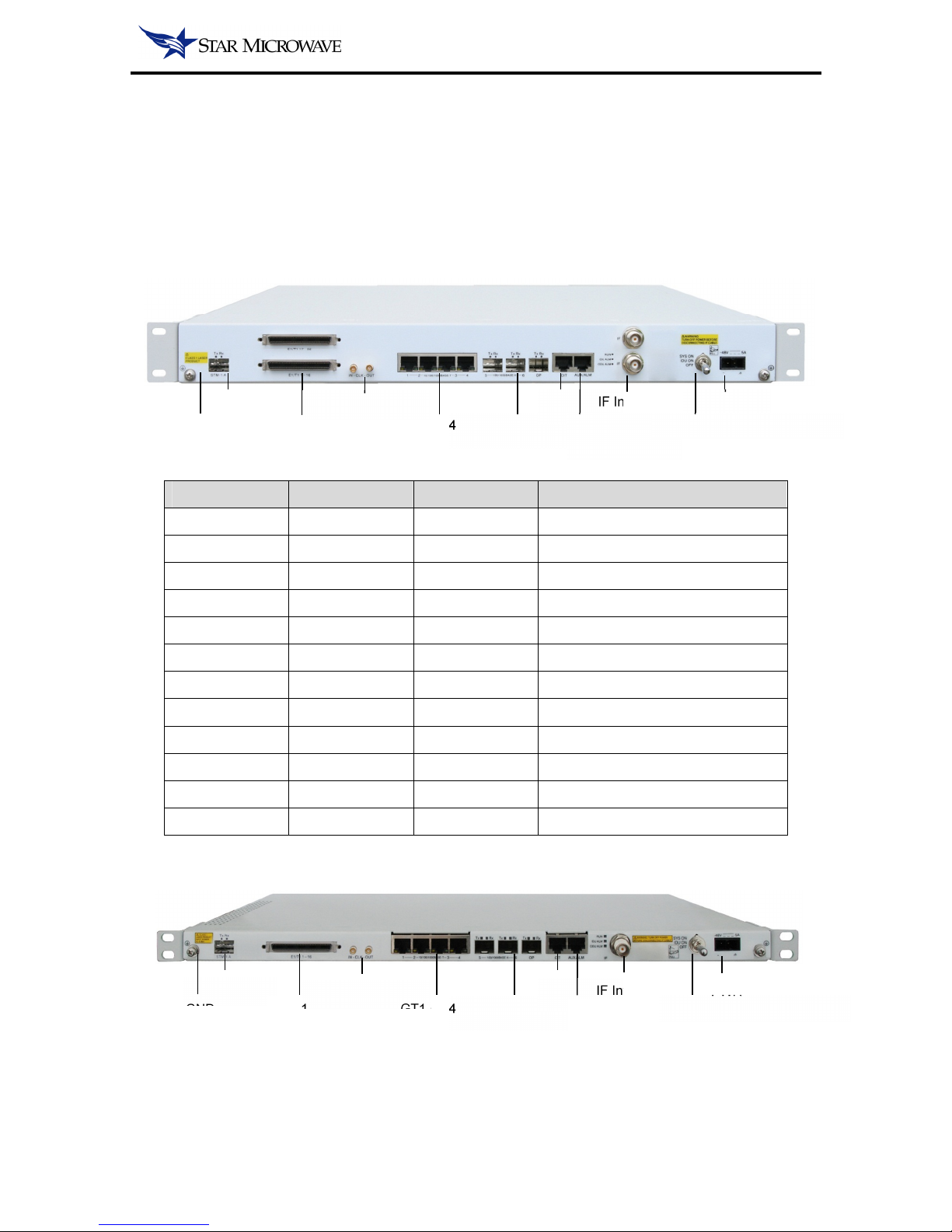
1.1.1 IDU INTERFACE DESCRIPTION
Figure 1-1 1U IDU Unit Front Penal Interface
Table 1-1 Interface Description
Interface Connector Quantity Remark
PWR Polarized plug 1 -48V DC and lower than 5A
PWR Switch - 1 Sys On / IDU ON / Off
IF Interface TNC 1 | 2 Connect TNC to N-type IF cable
AUX / Alarm RJ-45 1 AUX and alarm reuse
CIT (Serial) RJ-45 1 RS232 cable
OP SFP 1 Support 100/1000/2000Mbps
GE 5~6 SFP 2 Support 100/1000Mbps
GE 1~4 RJ-45 4 Support 10/100/1000Mbps
External Clock MCX 1 2.048MHz clock in & out
T1 MDR68 0 | 16 | 32 TDM interface
STM-1 SFP 1 STM-1 transfer interface
GND M8 screw 2 Grounding connect position
Figure 1-2 0.5U IDU Unit Front Penal Interface
GND
STM-1
GT1-GE4 GE5-GE7
IF Interface PWR CIT
AUX/Alarm Sys ON / IDU ON / OFF T1
External Clock
GND
STM-1
GT1-GE4 GE5-GE7
IF Interface
PWR
CIT
AUX/Alarm
Sys ON / IDU ON / OFF
T1
External Clock
Star Microwave Cirius SHC , 2016
Table 1-2 IDU LED Indicator Instruction
Indicator Status Description
RUN
flash (Green) System on boot
On (Green) System operates normal
Off No power in or system boot failure
IDU ALM
On (Red) The system detect a IDU alarm
Off IDU normal operation
ODU ALM
On (Red) The system detect a ODU alarm
Off ODU normal operation
Table 1-3 IDU Chassis Mechanical
Parameter Description
Dimension 438×280×44 (W×D×H, mm)
Weight 4.5Kg
1.1.2 DC POWER
IDU required -48V DC power source which maximum current does not exceed 5A, and the power
positive electrode must connect to ground.
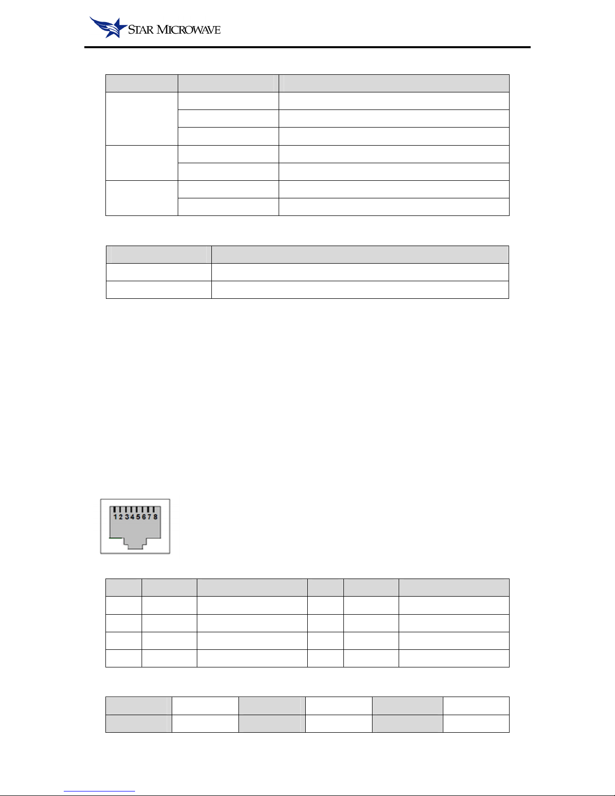
1.1.3 CIT
IDU support Serial ASCII, used Hyper Terminal with RS-232 protocol for the underlying operation.
Figure 1-3 CIT Port
Table 1-4 CIT Port Pin Definition
Pin Signal Function Pin Signal Function
1 Reserved - 5 GND Ground
2 Reserved - 6 TX Send data (Output)
3 RX Receive Data (Input)
7 Reserved -
4 Reserved - 8 Reserved -
Table 1-5 CIT Port Parameters
Bit Rate: 115200 bit/s Data Bits: 8 Parity: None
Stop Bits: 1 Flow Con.: None Emulation: Auto
Star Microwave Cirius SHC , 2016
1.1.4 ETH
Each IDU Unit supports four 10/100/1000Mbps electrical Ethernet ports and three 100M/1000Mbps
optical Ethernet ports. Optical Ethernet port used SFP module.
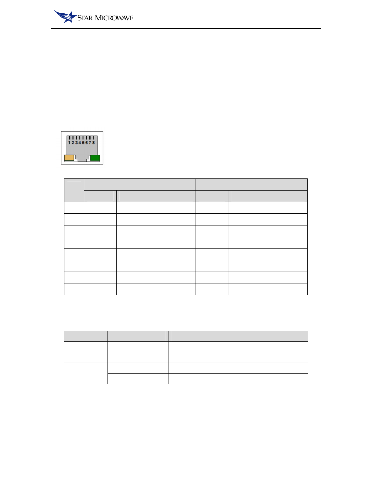
Electrical port supports MDI and MDI-X auto-negotiation mode. RJ-45 connector front view and pin
definitions in Figure 1-4 and Tables 1-6 shown.
Figure 1-4 Ethernet Port
Table 1-6 RJ-45 MDI/MDI-X Pin Definition
Pin
No.
10/100/1000 BASE-T MDI 10/100/1000 BASE-T MDI-X
Signal Function Signal Function
1 BI_DA+ Bi-directional pair A+ BI_DB+ Bi-directional pair B+
2 BI_DA- Bi-directional pair A- BI_DB- Bi-directional pair B-
3 BI_DB+ Bi-directional pair B+ BI_DA+ Bi-directional pair A+
4 BI_DC+ Bi-directional pair C+ BI_DC+ Bi-directional pair C+
5 BI_DC- Bi-directional pair C- BI_DC- Bi-directional pair C-
6 BI_DB- Bi-directional pair B- BI_DA- Bi-directional pair A-
7 BI_DD+ Bi-directional pair D+ BI_DD+ Bi-directional pair D+
8 BI_DD- Bi-directional pair D- BI_DD- Bi-directional pair D-
RJ-45 connector with two LED indicators and the Instruction is shown in Table 1-7.
Table 1-7 RJ-45 LED Indicators
Indicator Status Description
Yellow
(ACT)
Flash Port has send or receive data
Off Port hasn’t send or receive data
Green
(LINK)
Green Link connected
Off Link disconnected

Star Microwave Cirius SHC , 2016
1.1.5 T1
Uses MDR68 connector connects from IDU to Interface Adapter. Connector view and pin definitions
in Figure 1-5, Tables 1-8 and Tables 1-9 shown.
Figure 1-5 TMD RJ-45/BNC Port
Table 1-8 T1 RJ-45 Pin Definition
Pin Signal Function Pin Signal Function
1 RX+ Receive data (+) 5 TX- Send Data (-)
2 RX- Receive data (-) 6 GND Ground
3 GND Ground 7 Reserved -
4 TX+ Send Data (+) 8 Reserved -
Table 1-9 T1 BNC Pin Definition
Pin Signal Function Pin Signal Function
Contact
RX Receive Data Contact
TX Send data
Shell GND Ground Shell GND Ground
IN — 10 — OUT
Star Microwave Cirius SHC , 2016
2 SYSTEM SOFTWARE
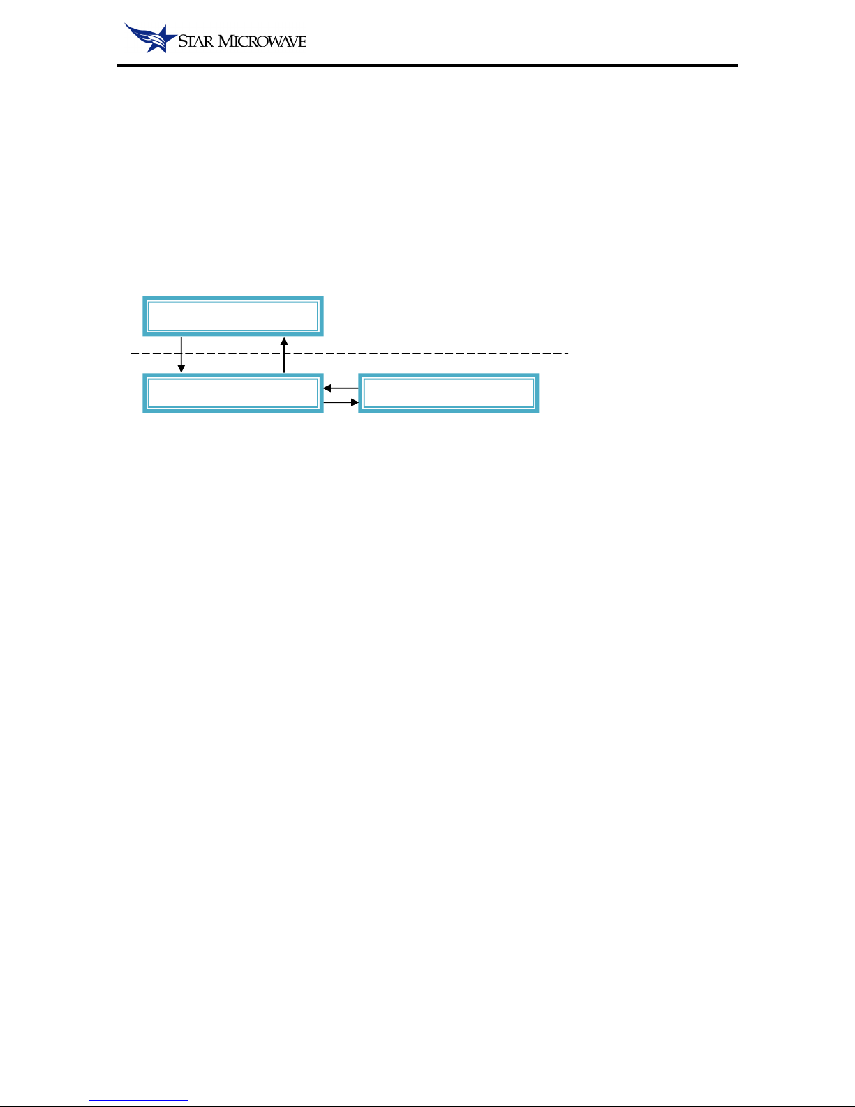
Cirius HM system software is divided into three parts: NMS software, IDU software and ODU
software.
The software architecture is shown in Figure 2-1, the NMS software used the IP communicate with
IDU.
Figure 2-1 Software Architecture
2.1 NMS SOFTWARE
Star Microwave Service Corporation feature provides T-NMS unified management platform which
can meet the requirements for transmission network management.
2.2 IDU SOFTWARE
IDU software is responsible for the management, monitoring and control of the operational status of
the IDU. The IDU software is also responsible for communication with the ODU software to
manage and control the ODU.
IDU software management provides a Web GUI access.
2.3 ODU SOFTWARE
ODU software is responsible for the management and control of the ODU operation. ODU software
according the IDU software parameters controls the ODU operation. At the same time, ODU
software reports the ODU status to the IDU software.
NMS Software
IDU Software
ODU
Software
Star Microwave Cirius SHC , 2016
3 CONFIGURATION IN WEB GRAPHIC USER INTERFACE
3.1 LOGIN
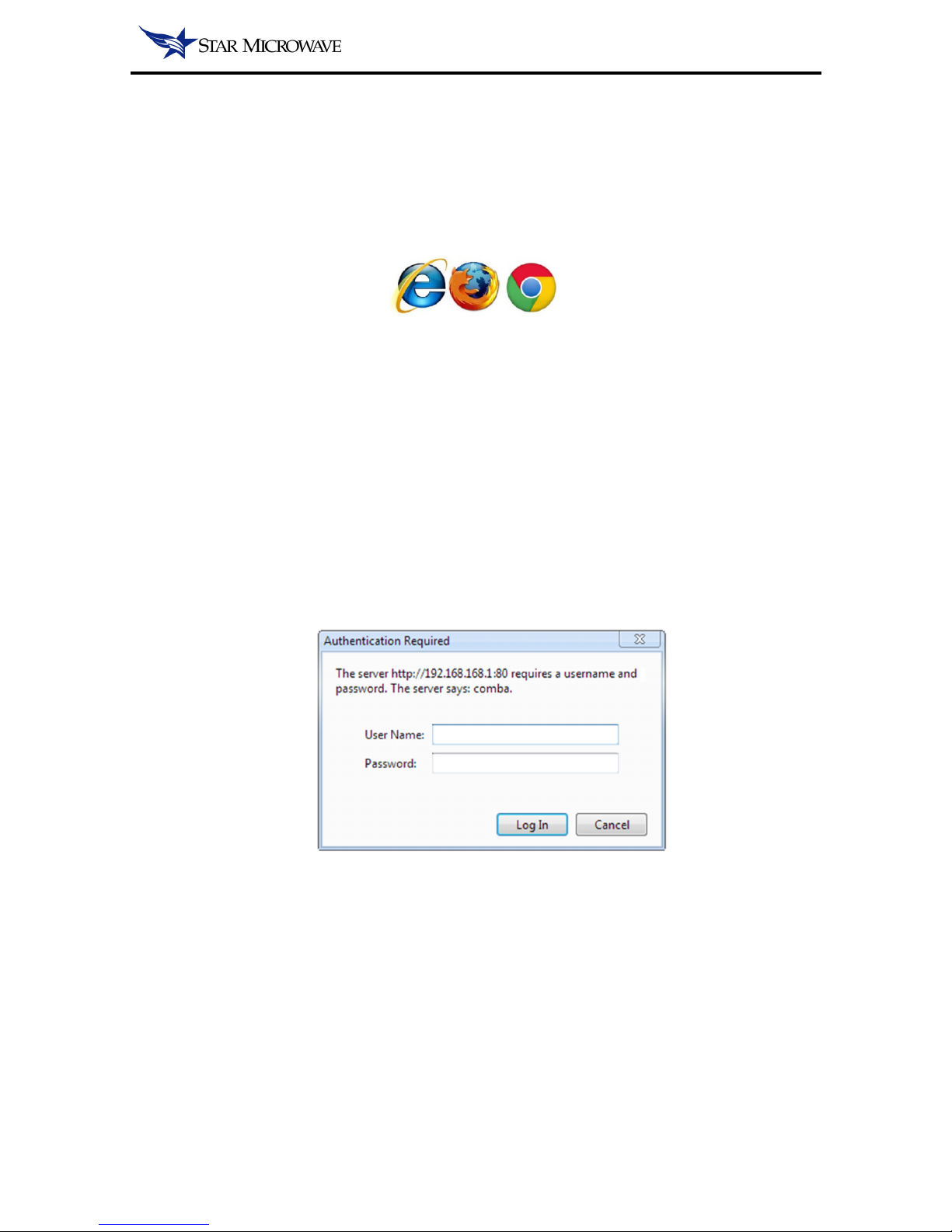
The supported browsers include ‘Internet Explore’, ‘Mozilla Firefox’ and ‘Google Chrome’.
Follow steps below to achieve the connection with web interface:
Step 1: First the user needs to set the PC IP address as the one sharing the same network segment
with the IDU IP address. The Default IP address of IDU is 192.168.168.1.
Step 2: Then Open the browser and input the IDU IP Address in the address field. For instance, if
the IDU IP address is 192.168.168.1, then input the http//:192.168.168.1 in the address field. Then
click “Enter” key to continue.
Step 3: Log in with the user name ‘
admin
’ and the password ‘
123456
’ in the pop up window.
Figure 3-1 System Login Window
Star Microwave Cirius SHC , 2016
3.2 BRIEF DESCRIPTION
3.2.1 SYSTEM COMPOSITION
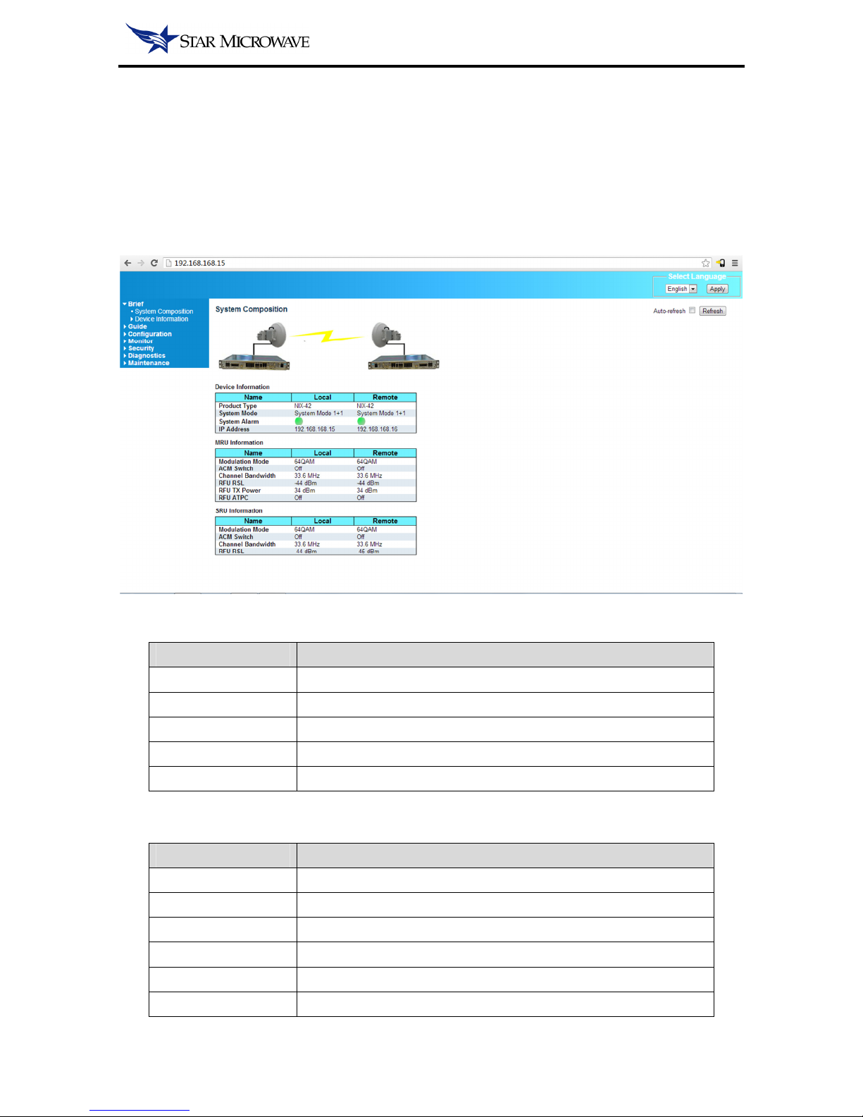
After logging in, the following window will show up. The main window in Web GUI is the System
Composition, which shows the system including the Local site and Remote site status.
Figure 3-2 System Composition Window
Table 3-1 Device Information
Parameter Description
Product Type Type of Star Microwave Service Corporation IDU model
System Mode System current configuration mode
System Alarm Indicate system alarm status
IP Address Web GUI IP address
TDM T1 Trib Num Indicate system current TDM channel quantity
Table 3-2 MRU Information
Parameter Description
Modulation Mode System current modulation mode
ACM Switch System adaptive coding & modulation function status
Channel Bandwidth System current used of channel bandwidth
ODU Tx Power 1st ODU current transmit power
ODU RSL 1st ODU current receive signal level
ODU ATPC 1st ODU ATPC function status

Star Microwave Cirius SHC , 2016
Table 3-3 SRU Information
Parameter Description
Modulation Mode System current modulation mode
ACM Switch System adaptive coding & modulation function status
Channel Bandwidth System current used of channel bandwidth
ODU Tx Power 2nd ODU current transmit power
ODU RSL 2nd ODU current receive signal level
ODU ATPC 2nd ODU ATPC function status
NOTE:
• In order to display the remote side system information, you must set the remote side IP
address so that the local system can inquiry and display.
The operation of set remote IP address can refer section 3.4.2.2.

Star Microwave Cirius SHC , 2016
3.2.2 INFORMATION
In the main system information window, user is able to check the system information, include
software and hardware version.
Figure 3-3 System Information Window
NOTE:
• Some item will display N/A according the different system mode because of useless.
Table 3-4 System Information
Parameter Description
Product Type Star Microwave Service Corporation IDU model
SN A unique code assigned for identification of a IDU
System Mode System current configuration mode
System Time System current date and time
MAC Address IDU’s media access control address
IP Address IDU’s internet Protocol address, use for access Web GUI
Monitor Firmware V. System current used monitor firmware version
MRU FPGA Ver. Master Radio Unit FPGA version
SRU FPGA Ver. Slaver Radio Unit FPGA version (hardware depends)
MSU FPGA Ver. Master Service Unit FPGA version (hardware depends)
SSU FPGA Ver. Slaver Service Unit FPGA version (hardware depends)

Star Microwave Cirius SHC , 2016
Table 3-5 Modem Information
Parameter Description
Firmware Version System current modem firmware version
Bandwidth System current used of channel bandwidth
Modulation Mode System current modulation mode
Demodulation State Shown whether the modem demodulation normal
MER Used to measure the Modulation Error Ratio
Table 3-6 ODU Information
Parameter Description
Firmware Version System current ODU firmware version
Tx Frequency ODU transmitter transmitted frequency
Rx Frequency ODU receiver received frequency
Tx Power ODU current transmit power
RSL ODU current receive signal level
SSPA Indicate whether the ODU working or mute
ATPC Switch Indicate whether the ATPC function on or off
 Loading...