

StarMax STFFS40-8JAF Owner's Manual
OWNER’S MANUAL
READ AND SAVE THESE INSTRUCTIONS
OPERATION INSTRUCTIONS
16” STAND FAN
MODEL: STFFS40-8JAF
145x210mm MRP5621-001 FS40-8JA 说明书 365 20150307
Read Rules for Safe Operation and Instructions Carefully.
1. Do not leave the fan running unattended.
2. Keep electrical appliances out of reach from Children or infirm
persons. Do not let them use the appliances without supervision.
3. If the supply cord is damaged, it must be replaced by
manufacturer or its service agent or a similarly qualified person in
order to avoid a hazard.
4. This appliance can be used by children aged from 8 years and
above and persons with reduced physical, sensory or mental
capabilities or lack of experience and knowledge if they have been
given supervision or instruction concerning use of the appliance in
a safe way and understand the hazards involved. Children shall
not play with the appliance. Cleaning and user maintenance shall
not be made by children without supervision.
5. When the fan was assembled, the rotor blade guard shall not be
taken off anymore
- Prior cleaning unplug the fan
- The rotor guard shall not be dissembled/opened to clean the
rotor blades
- wipe the fan enclosure and rotor blade guard with a slightly damp
cloth
1. Never insert fingers, pencils, or any other object through the grille
when fan is running.
2. Disconnect fan when moving from one location to another.
3. Be sure fan is on a stable surface when operating to avoid
overturning.
4. DO NOT use fan in window, rain may create electrical hazard.
5. Indoor use only.
1
CAUTION
WARNING
RULES FOR SAFE OPERATION
Round base
Oscillation knob
Speed
control
buttons
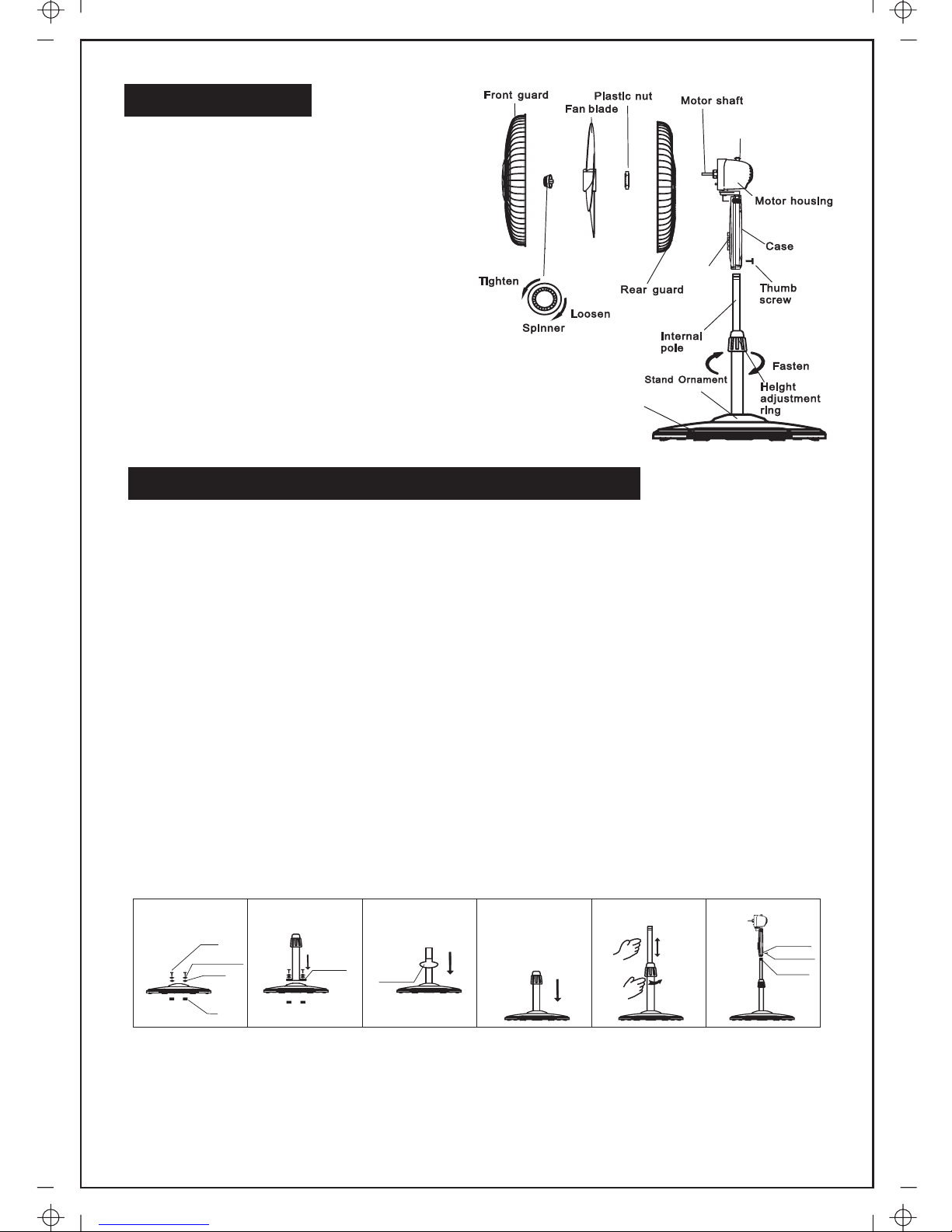
1. Unpack the packing box and check the parts by referring to the part figure.
From the round base, loosen the 4 screws located in the center. (See Fig.1)
2. Set the column and align the screw holes. (See Fig.2)
3. Tighten the screws. (If you can't tighten, check the nuts on the bottom of the
round base.)
4. To attach the stand (cover for the base) unscrew the height adjustment ring
located on the top of the column, slide the ornament down the external pole
and reattach the height adjustment ring. (See Fig.3, Fig.4)
5. From the external pole, loosen the height adjustment ring and adjust the
internal pole to the desired height. Note: If you can't find the internal pole, it
slides inside the external pole. You can pull it out from the external pole.
(See Fig.5)
6. To attach the head unit to the column, loosen the thumb screw on the bottom
of the head unit.
7. Place the head unit on the column and tighten the thumb screw in alignment with
the groove on the internal pole.(See Fig.6)
Fig.1 Fig.2 Fig.3
Fig.4 Fig.5 Fig.6
Screw
Spring washer
Washer
Motherboard
Stand
Ornament
LOOSE
Mounting hole
Thumb screw
Annular
groove
Nut
PARTS NAMES
ROUND BASE & COLUMN UNIT ASSEMBLY
2
 Loading...