

Page 1
®
CONVEYOR
OVEN
MODEL
UM3240
UM3255
Installation and
Operation
Instructions
2M-Z9045 Rev. D 6/26/2007
UM3240
UM3255
1
Page 2

SAFETY SYMBOL
Using any part other than genuine Star factory supplied parts relieves the
manufacturer of all liability.
Star reserves the right to change specifi cations and product design without
notice. Such revisions do not entitle the buyer to corresponding changes,
improvements, additions or replacements for previously purchased
equipment.
Due to periodic changes in designs, methods, procedures, policies and
regulations, the specifi cations contained in this sheet are subject to change
without notice. While Star Manufacturing exercises good faith efforts to provide
information that is accurate, we are not responsible for errors or omissions
in information provided or conclusions reached as a result of using the
specifi cations. By using the information provided, the user assumes all risks in
connection with such use.
These symbols are intended to alert the user to the presence of
important operating and maintenance instructions in the manual
accompanying the appliance.
RETAIN THIS MANUAL FOR FUTURE REFERENCE
NOTICE
MAINTENANCE AND REPAIRS
Contact your local authorized service agent for service or required maintenance. Please record the model
number, serial number, voltage and purchase date in the area below and have it ready when you call to
ensure faster service.
Model No.
Serial No.
Voltage
Purchase Date
Authorized Service Agent
Reference the listing provided with the unit
or
for an updated listing go to:
Website: www.star-mfg.com
E-mail Service@star-mfg.com
Telephone: (800) 807-9054 Local (314) 781-2777
The Star Service Help Desk
Business 8:00 am to 4:30 p.m. Central Standard Time
Hours:
Telephone: (800) 807-9054 Local (314) 781-2777
Fax: (800) 396-2677 Local (314) 781-2714
E-mail Parts@star-mfg.com
Service@star-mfg.com
Warranty@star-mfg.com
Website: www.star-mfg.com
Mailing Address: Star Manufacturing International Inc.
10 Sunnen Drive
St. Louis, MO 63143
U.S.A
2
2
3
Page 3
CAUTION
CAUTION
IMPORTANT
POST, IN A PROMINENT LOCATION, THE EMERGENCY TELEPONE NUMBER OF YOU
LOCAL GAS SUPPLIER AND INSTRUCTIONS TO BE FOLLOWED IN THE EVENT YOU
SMELL GAS.
Instructions to be followed in the event you smell gas shall be obtained by consulting the local
gas supplier. If the smell of gas is detected, immediately call the emergency phone number of
your local gas company. There personnel and provisions available to correct the problem.
FOR YOUR SAFETY DO NOT STORE OR USE GASOLINE OR OTHER
FLAMMABLE VAPORS AND LIQUIDS IN THE VICINITY OF THIS OR ANY OTHER
APPLIANCE.
The installation of the Appliance must conform to the NATIONAL FUEL GAS CODE
"ANSI Z223.1 - LATEST EDITION" AND ALL LOCAL GAS COMPANY RULES AND
REGULATIONS.
IN CANADA INSTALLATION SHALL BE IN ACCORDANCE WITH THE CURRENT CAN/
CGA-B149.1 NATURAL GAS INSTALLATION CODE OR CAN/CGA-B149.2 PROPANE
INSTALLATION CODE AND LOCAL CODES WHERE APPLICABLE.
IMPROPER INSTALLATION, ADJUSTMENT, ALTERATION, SERVICE, OR
MAINTENANCE CAN CAUSE PROPERTY DAMAGE, INJURY, OR DEATH. READ
ALL INSTRUCTIONS THOROUGHLY BEFORE INSTALLING OR SERVICING THIS
EQUIPMENT.
IMPORTANT
An electrical wiring diagram for the oven is located on the inside cover of the
Control Box Top Lid.
NOTICE
THIS APPLIANCE SHALL BE INSTALLED IN CONFORMITY WITH CURRENT
REGULATIONS & USED ONLY IN A WELL VENTILATED LOCATION. CONSULT THE
INSTRUCTIONS BEFORE INSTALLING AND USING THE APPLIANCE.
AT, CH, CZ, DK, ES, FI,
GB, GR, HU, IE, IT, NO,
PT, SE
GAS I2H I2L I2E I2E+
P
(mBAR)
G20 @ 20 G25 @ 25 G20 @ 20 G20 @ 20/25
Gas/Country Designations
NL LU, DE BE, FR
1
Page 4

®
UM3240 - UM3255 CONVEYOR OVEN
TABLE OF CONTENTS
page
Important Warnings 1
Specifi cations 3
Oven Components 4
General Information 5
Purchaser’s Responsibilities 5
Important Safety Information 6
INSTALLATION INFORMATION 7
Location 7
Gas Supply Rating & Sizing 7
Access Considerations 7
Electrical Connection 8
IEC/CEE Equipotential Ground 8
Pressure Regulation 9
Pressure Testing 9
Ventilation 10
Smoke Candle Test 10
Base Pad Assembly 11
Oven to Base Assembly 11
Stacking Instructions 12
Conveyor Installation 13
Conveyor Belt Direction 14
Restraint Requirement 15
OPERATING INSTRUCTIONS
Safety Operating Instructions 16
Operation 16
Turn Unit On 17
Adjusting Time & Temp 17
Shut Down Procedures 17
DISPLAY INFORMATION
Store Level 18
Manger Level 18
Additional Functions 18
Error Codes 18
Bake Time versus Temp 19
Conveyor Speed 19
Time of Delivery 19
MAINTENANCE INSTRUCTIONS
Daily, Monthly, 3 Months, Annually 20-21
Nozzle Finger Assembly / Dissembly 21
Conveyor Belt Tension 22
Conveyor Belt Link Removal 22
Wiring Diagram 23
EXPLODED VIEW & PARTS LIST
Front Panel Assembly 24-25
Rear Panel Assembly 26-27
Conveyor Assembly 28-29
Control Box Assembly 30-31
Control Box Door Assembly 32-33
Manifold & Blower/Burner Assembly 34-35
Warranty 36
2
Page 5

SPECIFICATIONS
UM3240-NAT, UM3240-LP
Gas Rating/Connection: 120,000 BTU/hr (504 kcal/min)
3/4" NPT female pipe connection (BSP adapter supplied on CE models)
Gas Supply Pressure: Natural - 5-6" water column (15-30 mBar) @ rated fl ow
Propane - 11-12" water column (27.5-30 mBar) @ rated fl ow
Electrical Supply: Separate 15 Amp 208-240VAC, single phase, 50/60 Hz service per Oven
Approximate Weight (Single Oven without base): Shipping - 868 Lbs (393.7 kg)
(Single/Double Base): Shipping - 177.3 Lbs (80.4 kg)
(Triple Base): Shipping - 188.3 Lbs (85.4 kg)
(Fingers): Shipping - 91.5 Lbs (41.5 kg)
(Single Oven with base): Installed - 717 Lbs (325.2 kg)
(Double Oven with base): Installed - 1292 Lbs (586 kg)
(Triple Oven with base): Installed - 1878 Lbs (851.8 kg)
Dimensions: Width: 80.2" (203.7 cm) - w/control panel door closed
96.2" (244.3 cm) - w/control panel door open
Depth: 60.5" (153.7 cm) - Front Door(s) Closed
102.9" (261.4 cm) - Front Door(s) Open
Height: 43.1" (109.5 cm) - Single Oven with Stand
61.1" (155.2 cm) - Double Oven with Stand
63.5" (161.4 cm) - Triple Oven with Dolly
Recommended Minimum Clearances:
Rear of Oven to Wall 0" (0 cm)
Conveyor Extensions to Wall 6" (0 cm)
Allowing 16.25" on the control panel door to open will allow for easier service
UM3255-NAT, UM3255-LP
Gas Rating/Connection: 150,000 BTU/hr (630 kcal/min)
3/4" NPT male pipe connection (BSP adapter supplied on CE models)
Gas Supply Pressure: Natural - 5-6" water column (15-30 mBar) @ rated fl ow
Propane - 11-12" water column (27.5-30 mBar) @ rated fl ow
Electrical Supply: Separate 15 Amp 208-240VAC, single phase, 50/60 Hz service per Oven
Approximate Weight (Single Oven without base): Shipping - 922 Lbs (418.2 kg)
(Single/Double Base): Shipping - 205.3 Lbs (93.1 kg)
(Triple Base): Shipping - 216.3 Lbs (98.1 kg)
(Fingers): Shipping - 122 Lbs 55.3 kg)
(Single Oven with base): Installed - 827 Lbs (375.1 kg)
(Double Oven with base): Installed - 1484 Lbs (673.1 kg)
(Triple Oven with base): Installed - 2152 Lbs (976.1 kg)
Dimensions: Width: 94.6" (240.3 cm) - w/control panel door closed
110.6" (280.9 cm) - w/control panel door open
Depth: 60.5" (153.7 cm) - Front Door(s) Closed
102.9" (261.4 cm) - Front Door(s) Open
Height: 43.1" (109.5 cm) - Single Oven with Stand
61.1" (155.2 cm) - Double Oven with Stand
63.5" (161.4 cm) - Triple Oven with Dolly
Recommended Minimum Clearances:
Rear of Oven to Wall 0" (0 cm)
Conveyor Extensions to Wall 6" (0 cm)
Allowing 16.25" on the control panel door to open will allow for easier service
3
Page 6
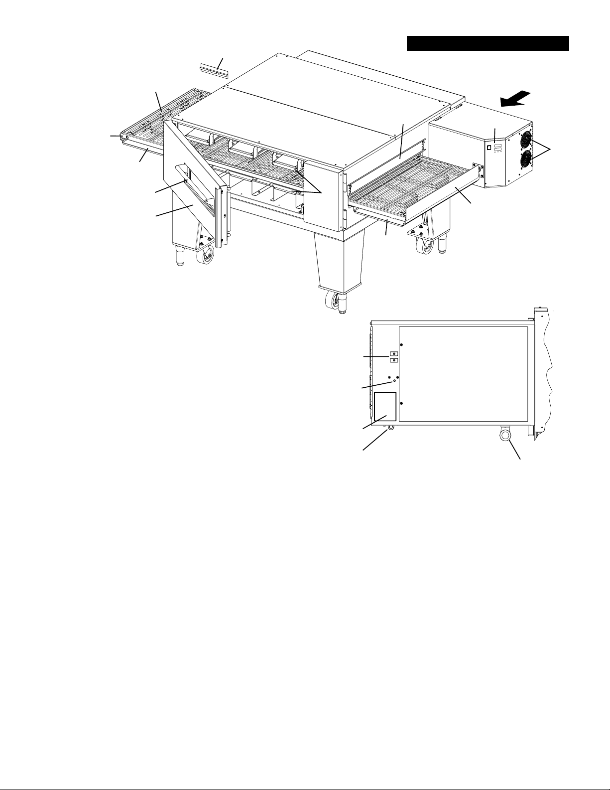
OVEN COMPONENTS
I
A
G
VIEW A
C
B
H
F
J
I
E
H
IL1173
OVEN COMPONETS DESCRIPTION
A: Conveyor Belt: Moves the product through the oven
B: Conveyor Assembly: Supports the Conveyor Belt, the
ends fold up for easy removal.
C: Control Panel: Bright Red Display for easy notifi cation
of ovens current operation, and buttons for making quick
modifi cations.
D: Air Intake: Located on the end of the control box to pre-
vent the electronic controls from overheating as well as
to allow for a more direct air fl ow into the blowers. DO
NOT BLOCK these air intakes and wipe them clean on a
regular basis.
E: Machinery Compartment Access Door: Allows access
to the oven’s interior Finger components.
F: Access Window: This allows easy access to the cooking chamber, for product to be placed in to give
a shorter or additional cooking time to the product.
G: Heat Shutter: Can be adjusted to various settings, depending on product being placed in the oven, to
prevent heat loss
H: Crumb Tray: Catches crumbs and other material that drops through the conveyor belt. Located at
each end of the conveyor assembly.
I: Conveyor End & Side Stops: Prevents product from falling off of the moving conveyor.
J: Fingers: Projects streams of hot air onto the product.
K: Circuit Breaker 10Amp: Protects components from over amperage.
L: Hi-Limit Reset: Monitors inside cooking temperature and will only trip when unitended temperature is
reached.
M: Nameplate: Has specifi c information regaring this units electrical & gas requirements as well as the
units serial number which is needed for any service that will be required. This number should be written
in the inside cover of this manual and kept for future needs
N: Electrical Input: Electrical Supply connection must meet all national and local electrical code
requiremtns.
O: Gas Connection: The installation must confi rm with local codes or in the absence of local codes, with
the National Fuel Gas Code, ANSI Z2223.1 latest edition.
K
L
M
N
VIEW A
O
D
4
Page 7

GENERAL INFORMATION
This equipment is designed and sold for commercial use only by personnel trained and experienced
in its operation and is not sold for consumer use in and around the home nor for use directly by
the general public in food service locations.
Before using your new equipment, read and understand all the instructions & labels
associated with the unit prior to putting it into operation. Make sure all people associated
with its use understand the units operation & safety before they use the unit.
First and foremost, each crate should be examined before signing the Bill of Lading to report any
visible damage by the freight carrier in transit and to account for the proper number of crates.
If there is apparent damage, arrangements should be made to fi le a claim against the carrier
within 15 days. Interstate Commerce Regulations require that the claim must be initiated by the
consignee. Proper and secure storage facilities should be arranged for the oven(s) if necessary
to protect it from outdoor or damp conditions at all times before installation.
-IMPORTANT-
When you have all the crates unloaded, open the crates and remove all plastic covers. Inspect
at once for concealed damage. If anything appears to be damaged, contact the appropriate
persons immediately to fi le a damage claim. After completing this inspection, fi nish unpacking
the oven. Be sure to remove all paper protection and packing material from the unit prior
to lighting.
NOTICE
This appliance must be installed with a stand and casters designed by Star Manufacturing as part
of a complete installation. The installation must also include a connector complying with either
ANSI Z21.69 or CAN/CGA-6.16 and a quick-disconnect device complying with either ANSI Z21.41
or CAN1-6.9. It must also be installed with restraining means to guard against transmission of
strain to the connector as specifi ed in the appliance manufacturer's instructions.
For your protection, we recommend a qualifi ed installing agency install this appliance. They
should be familiar with gas installations and your local gas requirements. In any case, your gas
company should be called to approve the fi nal installation.
This appliance, its pressure regulator, and its individual shutoff valve must be disconnected
from the gas supply piping system during any pressure testing of that system at test pressures
in excess of 1/2 PSIG. This appliance and its pressure regulator must be isolated from the gas
supply piping system by closing its individual manual shutoff valve during any pressure testing
of the gas supply piping system at test pressures equal to or less than 1/2 PSIG.
PURCHASER'S RESPONSIBILITY
It is the responsibility of the purchaser:
1. To see that the gas and electric services for the oven are installed on site in accordance
with the manufacturer's specifi cations and municipal codes.
2. To see that all gas and electric services are connected properly by a qualifi ed installer of your
choice. All such connections must be in accordance with applicable code requirements.
3. To arrange for inspection and operation check-out by an authorized service technician.
The warranty becomes effective upon verifi cation of proper installation.
5
Page 8
CAUTION
CAUTION
CAUTION
IMPORTANT SAFETY INFORMATION
Do not attempt to operate the oven until connection of utility service has been fully inspected
by an authorized service technician or a Star Service Representative. This service is required
by Star in order to assist the purchaser in proper start-up of the oven on site. Please note
the specifi c details on the Warranty and make certain that service connections are made to
proper utility services.
The warranty shall not apply if the oven is started up and operated prior to the utilities and
oven being inspected and check-out made by an authorized service technician or a Star
Service Representative.
IMPROPER INSTALLATION, ADJUSTMENT, ALTERATION, SERVICE, OR
MAINTENANCE CAN CAUSE PROPERTY DAMAGE, INJURY, OR DEATH. READ
ALL INSTRUCTIONS THOROUGHLY BEFORE INSTALLING OR SERVICING THIS
EQUIPMENT.
Post in a prominent location the emergency telephone number of your local
gas supplier and instructions to be followed in the event you smell gas. If the
smell of gas is detected, immediately call the emergency phone number of
your local gas company. They will have personnel and provisions available to
correct the problem.
It is required that the oven be placed under a ventilation hood to provide for
adequate air supply and ventilation.
CAUTION
CAUTION
CAUTION
WARNING
Minimum clearances must be maintained from all walls and combustible
materials. Minimum clearances for this unit should be 0 inches from the rear
and 6 inches from both sides. Keep the oven free and clear of all combustible
material, for use only on Non-Combustable fl oors.
Adequate clearance for air openings to the combustion control chamber on the
right side of the oven is required. Do not obstruct the ventilation holes in the
control panels as these provide the combustion air for the burner and cooling
air for the controls.
The oven is to be operated only on the type of gas and electricity shown on the
specifi cation plate. The burner will not operate and gas will not fl ow through
the burner without electric power.
If the supply cord is damaged, it must be replaced by the manufacture,
its service agent or similarly qualifi ed persons in order to avoid a hazard.
Star replacement parts are listed in the parts list section of this manual.
6
Page 9

INSTALLATION INFORMATION
THE INSTALLATION INSTRUCTIONS CONTAINED HEREIN ARE FOR THE USE OF
QUALIFIED INSTALLATION AND SERVICE PERSONNEL ONLY. INSTALLATION OR
SERVICE BY OTHER THAN QUALIFIED PERSONNEL MAY RESULT IN DAMAGE TO THE
OVEN AND/OR INJURY TO THE OPERATOR.
Qualifi ed installation personnel are individuals, a fi rm, a corporation, or a company which either
in person or through a representative are engaged in and responsible for:
1. The installation or replacement of gas piping and the connection, installation, repair, or
servicing of equipment.
2. The installation of electrical wiring from the electric meter, main control box, or service outlet
to the electric appliance.
Qualifi ed installation personnel must be experienced in such work, familiar with all precautions
required, and have complied with all requirements of state or local authorities having
jurisdiction.
UTILITY INSTALLATION
LOCATION
The well-planned and proper placement of your oven will result in long-term operator convenience
and satisfactory performance.
NOTE: On gas conveyor ovens, routine servicing can usually be accomplished within the limited
movement provided by the gas hose restraint. If the oven needs to be moved further from the
wall, the gas must fi rst be turned off and disconnected from the oven before removing the restraint.
Reconnect the restraint after the oven has been returned to its regular position.
It is essential that an adequate air supply to the oven be maintained to provide a suffi cient fl ow
of combustion and ventilation air. Follow these guidelines:
1. Place the oven in an area that is free of drafts.
2. Keep the oven area free and clear of all combustibles such as paper, cardboard, fl ammable
liquids, and solvents. Oven should only be used on Non-Combustible Floors.
3. Do not place the oven on a curb base or seal to a wall. This will restrict the fl ow of air and
prevent proper ventilation to the blower motors. This condition must be corrected to prevent
permanent damage to the oven.
4. On all models, tripping of the blower motor's thermal overload device indicates an excessive
ambient temperature at the back of the oven. This condition must be corrected to avoid
permanent damage to the oven.
GAS SUPPLY RATING AND SIZING
Calculations for pipe sizing must take into account the maximum usage rate of all other appliances
in the kitchen or one or more of the appliances will suffer from inadequate or dangerous
performance. The 3/4" NPT connection for the oven is generously sized for use in the control
box of the oven. However, unless the oven installation is within 10 feet of the main building gas
supply, the supply must be larger. For each oven, a 3/4" NPT fl exible quick connect hose and
full port gas shut-off valve is recommended as a MINIMUM. The main pipe supplying each oven
branch may need to be larger depending on the number of appliances serviced, the number
of elbows in the piping, and the pressure. This should be sized and installed by a professional
familiar with any local codes that may also affect the installation.
ACCESS CONSIDERATIONS
Locating the gas valve(s), quick connect hose(s) and electrical outlet(s) at the control box end
of the oven will allow easier access for any service visits. This improved access should make
any necessary service quicker resulting in less kitchen disruption. It will also allow easier
disconnection of electricity, gas, and restraints for cleaning around and behind the oven.
7
Page 10
WARNING
CAUTION
WARNING
ELECTRICAL CONNECTION
UTILITY INSTALLATION
Before making any electrical connections to this unit, check that the power supply is adequate
for the voltage, amperage, and phase requirements stated on the rating plate. A wiring diagram
is included herewith.
ENSURE THAT BOTH THE CIRCUIT BREAKER AND THE POWER (ON/OFF) SWITCH
IS IN THE OFF POSITION BEFORE PROCEEDING.
BE CERTIAN THAT ALL PACKING MATERIAL HAS BEEN REMOVED FROM INSIDE
THE OVEN'S CHAMBER.
When installed, this appliance must be electrically grounded and its installation must comply with
the National Electric Code, ANSI-NFPA 70, latest version, manufacturer's installation instructions,
and applicable local municipal building codes. In Canada, all electrical connections are to be in
accordance with CSA C22.1 - Canadian Electrical Code Part 1 and/or local codes.
This device is equipped with a 3-prong (grounded) plug for your protection against shock
hazard and should be plugged directly into a properly grounded three prong receptacle.
DO NOT cut or remove the grounded prong from this plug.
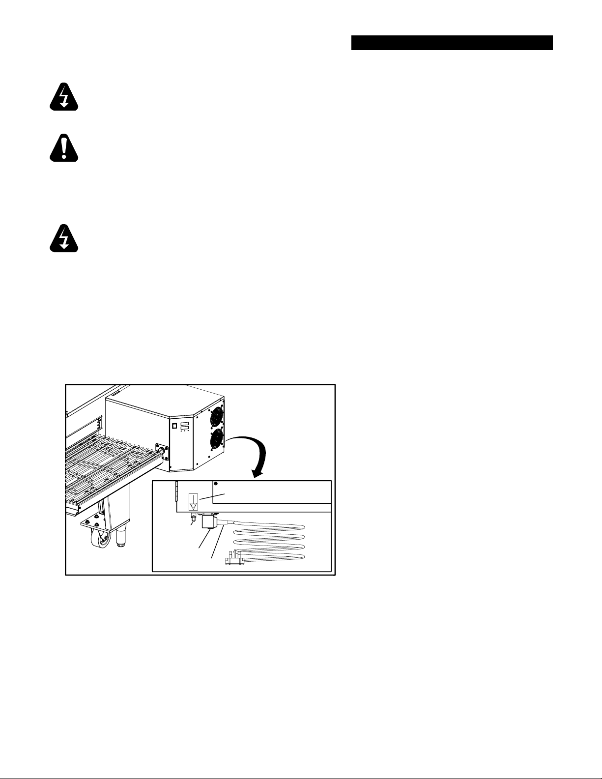
EQUIPOTENTIAL GROUNDING - CE ONLY
On CE units, connect an equipotental ground wire to the ground lug shown in the fi gure below.
The equipotential ground connection must meet current IEC/CEE and local code requirements.
The ground lug is found on the rear side of the control box, below the equipotential ground
symbol.
On certain CE/UK models install the IEC plug using the cord holder provided.
Symbol
Equipotential
Ground Lug
Cord Holder
IEC Plug
IL1242
IEC/CEE Equipotential Ground Connection
8
Page 11
CAUTION
WARNING
UTILITY INSTALLATION
PRESSURE TESTING GAS SUPPLY LINE
During pressure testing note the following:
1. The oven and its individual manual shut-off valve must be disconnected from the gas supply piping
system during any pressure testing of that system at test pressures in excess of 1/2 psig (3.45 kPa).
Turn OFF main gas shut-off valve or main gas supply line.
2. The oven must be isolated from the gas supply piping system by closing its individual manual shutoff valve during any pressure testing of the gas supply piping system at test pressures equal to or
less than 1/2 psig (3.45 kPa).
3. If incoming pressure is over 14" water column, a separate regulator for the oven must be installed
before the gas supply to the oven.
To prevent damage to the control valve regulator during the initial turn-on of
gas, it is very important to open the manual shut-off valve very slowly. After the
initial gas turn-on, the manual shut-off valve must remain open except during
pressure testing as outlined in the above steps or when necessary during service
maintenance.
NOTE: The supplied regulator is evaluated for a maximum gas supply pressure of
14" water column (34.5 mBar). The recommended maximum gas supply pressure
is 12" water column (29.9 mBar).
Installation must conform with local codes or, in the absence of local codes, with the National
Fuel Gas Code, NFPA54/ANSI Z223.1 - Latest Edition, the Natural Gas Installation Code
CAN/CGA-B149.1 or the Propane Installation Code CAN/CGA-B149.2 as applicable.
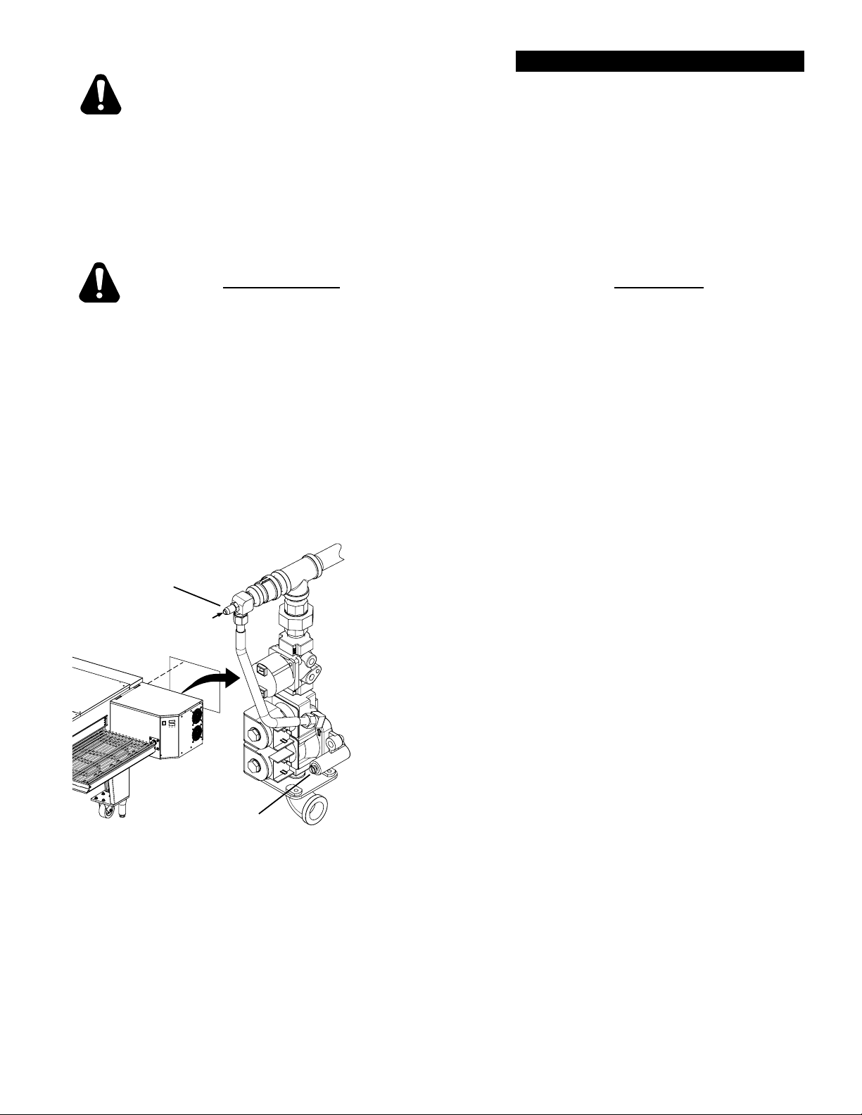
PRESSURE READING
TEST NIPPLE
SET-SCREW
GAS PRESSURE
ADJUSTMENT SCREW
IS UNDER CAP
Oven Manifold Regulator, w/Set Screw
IL1191
OVEN MANIFOLD PRESSURE REGULATION
Each oven has been adjusted at the factory to operate with
the gas specifi ed on the nameplate.
Each oven is supplied with a regulator to maintain the proper
gas pressure. The regulator is essential to the proper
operation of the oven and should not be removed or replaced
by another model unless approved by Star Manufacturing.
A pressure reading can be taken at the test nipple provided.
You must back the set-screw one turn for this test, be certain
to re-tighten when you are done. Failure to reset the setscrew to its original position will create a gas leak once the
unit is back in operation. The reading should be taken while
the oven is heating up & at high fi re. The regulator is located
on the bottom of the gas combination valve, just inside the
control box. Adjust gas manifold regulator gas pressure by
removing the cap and adjusting the regulator adjustment
screw to match the pressure listed on the name plate (3.5"
Nat, 4.8" Propane). Clockwise to increase, counterclockwise
to decrease.
9
Page 12
VENTILATION
INSTALLATION VENTILATION
A VENT IS REQUIRED: Local codes prevail. These are the "authority having
jurisdiction" as stated by the National Fire Protection Association, Inc. in NFPA
96-Latest Edition. For further ventilation information see below.
A ventilation hood is required to remove heat and cooking odors. For gas ovens, a ventilation
hood is also required to remove the products of combustion. The hood and HVAC installation
must meet local codes to gain approval by the authority having jurisdiction. Requirements may
vary depending on the location by city, county, and state. Obtain information from the authority
having jurisdiction to determine the requirements for your installation. Obtain information and
review copies of codes or documents that will be used to inspect and approve your installation.
Your ventilation hood supplier and HVAC contractor should be contacted to provide guidance. A
properly engineered and installed ventilation hood and HVAC system will expedite approval and
reduce oven maintenance costs. Proper ventilation is the responsibility of the oven's owner.
The ventilation hood must operate in harmony with the building HVAC system. (The effi ciency
of various hood designs makes it necessary to specify such a wide range of ventilator CFM.)
Make-up air must be supplied by either a hood design or the HVAC system to avoid a negative
pressure condition. This will vary with hoods from various manufacturers. Air supplied directly
from outside the building to the kitchen or oven area, non-tempered, could be used as supply
air but the design would have to accommodate potential operational changes.
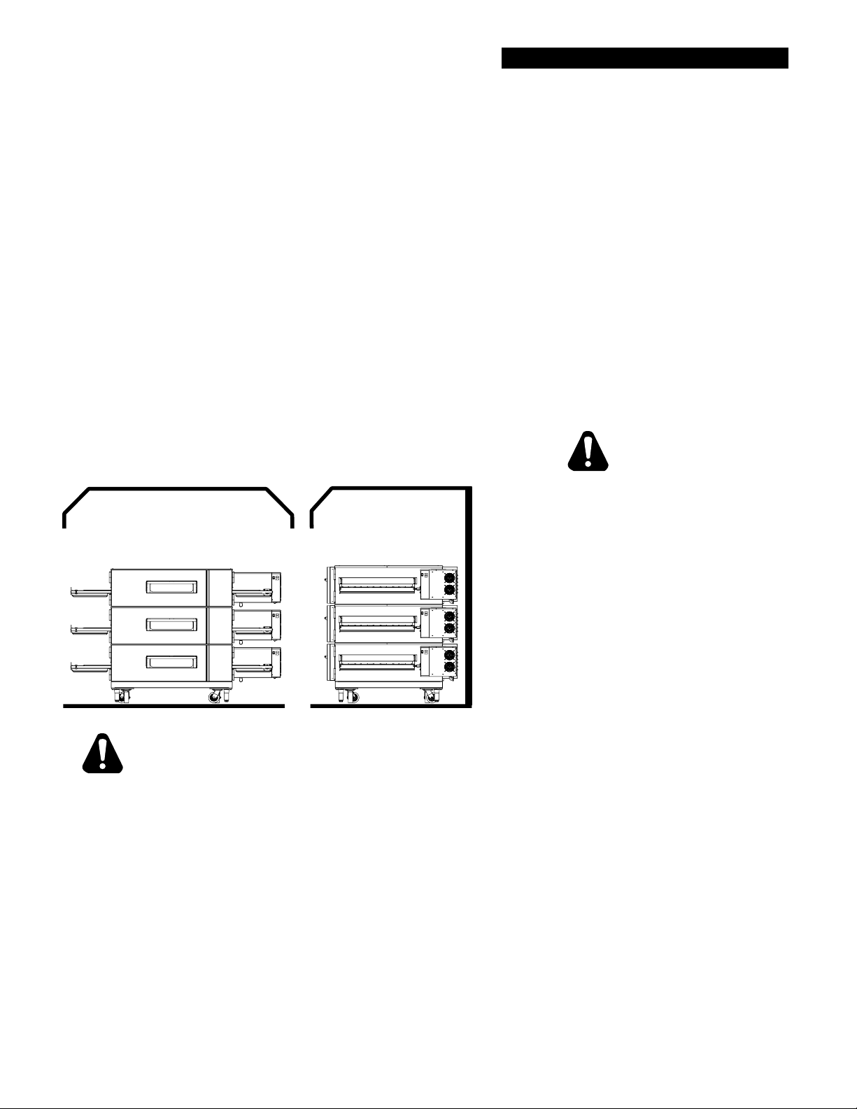
CAUTION
Prevent airfl ow through the cooking
VENTILATION
CAPTURE AREA
VENTILATION
CAPTURE AREA
RIGHT SIDE FRONT SIDE
tunnel. Air must NOT be directed onto
the oven's front or rear or to the sides
of the cooking area.
The following drawing shows a typical
installation and is intended to be a guideline.
This is not a rigid specification. Hood
dimensions and positioning over the oven
will vary with hood manufacturer & local
guidelines.
CAUTION
Damage sustained as a direct result of
improper ventilation will not be covered by
IL1177
the warranty.
Failure to properly vent the oven can be hazardous to the health of the operator
and may result in operational problems, unsatisfactory baking, and possible
damage to the equipment.
SMOKE CANDLE TEST
In order to verify the proper function of your ventilation system, a smoke candle test should
be done. If testing a multiple oven system, this test should be done on the bottom oven. The
conveyor coupling should be disconnected so conveyor does not move and the oven temperature
must be set and operating at a minimum of 480°F (249°C).
Test Procedure:
1. Wear heat-resistant gloves to prevent burns.
2. Put the smoke candle in an cake pan.
3. Insert candle through conveyor tunnel or oven
door. (Use Star Smoke Candle 2W-Z5668.)
4. Light the fuse of the smoke candle and
immediately center the pan in the oven cavity on
the conveyor belt (keeping the oven door and
window closed).
10
5. Observe the smoke pattern coming out of
all oven openings and the collection of this
smoke by the ventilation system.
6. All smoke from the oven must be captured
by the ventilation system.
Page 13

INSTALLATION OVEN ASSEMBLY
Plate Cover
Triple Stack Plate
Adj. Foot
CASTERS for TRIPLE OVEN
IL1176
Support Leg
Bottom Leg Plate
CASTERS for SINGLE & DOUBLE OVEN
Top Panel Rear
Top Panel Front
DETAIL
Oven
Caster
Caster
Adj. Foot
Alignment
Holes
A
Screw
Alignment
Studs
BASE PAD ASSEMBLY
Triple Stack Applications
1. Bolt the caster assembly to the Bottom
Leg Plate & Plate Cover using provided
hardware.
2. Screw the Foot Assembly in place as
shown.
3. Bolt the Bottom plate assembly to each
corner of the Base Pad Assy. using provided
hardware.
4. With assistance turn the Base Pad upright.
Single & Double Stack Applications
1. Install the support legs in position in each
corner of the Base Pad Assy. using provided
hardware.
2. Bolt the caster assembly to the Bottom Leg
Plate using provided hardware.
3. Screw the Foot Assembly in place as
shown.
4. Bolt the Bottom plate assembly to the
Support Leg securing with the washer & nuts
provided.
5. With assistance turn the Base Pad upright.
OVEN TO BASE ASSEMBLY
1. Remove any packaging material that was
shipped with the oven and base.
2. Prior to placing the oven onto the base
make sure the base insulation material is
positioned correctly.
3. With assistance, lift the oven and position it
onto the base.
4. For Dual or Triple Oven Installations,
go directly to STACKING INSTRUCTION.
5. Install the Top Panels on top of the oven
making sure to line-up the Alignment Holes
with their appropriate Alignment Holes, as
shown here. See Detail A.
6. Secure the Top Panels in place.
7. Roll the Oven into position, using a level
adjust the Feet until oven is level.
Base
Adj. Foot
IL1174
11
Top Rear Panel Top Front Panel
Alignment Stud
IL1205
DETAIL A
Front
Page 14

INSTALLATION OVEN ASSEMBLY
Top Panel Rear
Top Panel Front
Insulation
Oven
Insulation
Oven
Insulation
Stacking Corners
Alignment
DETAIL A
Screw
Holes
Screw
Alignment
Studs
STACKING INSTRUCTIONS
1. Remove any packaging material
that was shipped with the oven
and base.
2. Prior to placing the oven onto
the base make sure the base
insulation material is positioned
correctly.
3. With assistance, lift the oven and
position it onto the base.
4. Install the Stacking Corners, as
shown being sure to secure the
two rear with a screw.
5. Using an Oven Lift (see PreInstall Manual for specifi c Oven
Lifting Instructions) carefully
place the upper oven on top of
the lower oven. Note: Be careful
not to lift the unit by the Control
Box Assembly.
6. Be certain the insulation is
properly positioned.
7. Repeat steps 4 - 6 if for Triple
Oven Installations.
8. Install the Top Panels on top of
the oven making sure to line-up
the Alignment Holes with their
appropriate Alignment Studs, as
shown here. See Detail A.
9. Secure the Top Panels in place.
10. Roll the Oven into position, using
a level adjust the Feet until oven
is level.
Base
Adj. Feet
12
IL1175
Top Rear Panel Top Front Panel
IL1205
DETAIL A
Alignment Stud
Front
Page 15

CAUTION
INSTALLATION OVEN ASSEMBLY
CONVEYOR INSTALLATION
Conveyor installation can only be installed from the control panel/drive motor side. This needs
to be removed when cleaning the cooking chamber and removing the Nozzel Finger Assembly
for disassembly & cleaning.
ALLOW THE OVEN TO COOL BEFORE INSTALLING OR REMOVING THE CONVEYOR
ASSEMBLY.
1. With Nozzel Finger Assemblies in position, place the Conveyor Guides on its mounting
studs located at the opening at each end of the cooking chamber.
2. Open the conveyor assembly, pull on the conveyor belt making sure it moves freely
without obstruction.
3. With assistance, lift the conveyor and slide it along the Conveyor Guides into position from
the drive motor side, be certain the crumb tray brackets are on the outside of the oven,
and the Drive Collar is on the control panel side as shown below.
4. Once the conveyor assembly is installed, slide the Drive Collar over the Drive Cog to sync
the conveyor with the drive motor.
Conveyor
Conveyor
Guide
IL1186
Drive Collar
Drive Cog
IL1185
Conveyor Belt
not shown
Crumb Tray
Bracket
13
Page 16

INSTALLATION OVEN ASSEMBLY
CONVEYOR BELT DIRECTION
Conveyor travel is factory set for left to right operation. If the opposite direction is required, the
polarity of the drive motor must be reversed.
To reverse polarity:
1. DISCONNECT THE POWER CORD FROM THE UNIT.
2. Open the Control Box Door and swing open.
3. Find the Drive Motor and follow the wires back until you fi nd the connector shown
below.
4. Pressing your small screw driver, into the square hole on top of the connector, you
will be able to remove & reverse the black & brown wires of the connector on the
DRIVE MOTOR SIDE ONLY.
5. Close the Control Box Door, and secure with hardware.
6. Reconnect the unit to its electrical power source, and test for proper conveyor belt
direction change.
Yellow
White
Red
Grey
Brown
Black
Black
Harness
Grey
Brown
Harness
Wiring
Red
Wiring
White
Drive
Motor
Yellow
Drive
Motor
Screwdriver
Access Holes
Brown
Black
Black
Brown
Grey
Grey
(FACTORY PRESET)
LEFT TO RIGHT
CONVEYOR BELT DIRECTION
Yellow
White
Red
RIGHT TO LEFT
CONVEYOR BELT DIRECTION
Yellow
White
Red
14
IL1183
Page 17

INSTALLATION RESTRAINT
Eyebolt
WALL STUD OR
MASONRY WALL
Restraining Kit
Eyebolt
RESTRAINT REQUIREMENT
1. The installation shall be made with a gas connector that complies with local codes for
connectors for movable gas appliances and a quick-disconnect device that complies
with local codes for such devices in use with gas fuel.
NOTE: Because the oven is equipped with casters, the gas line connection shall be made
with a connector that complies with the Standard for Connectors for Movable Gas Appliances,
ANSI Z21.69 • CSA 6.16, and a quick-disconnect device that complies with the Standard for
Quick-Disconnect Devices for Use With Gas Fuel, ANSI Z21.41 • CAN1-6.9.
IL1187
2. The installation of the restraint must limit the movement of the oven(s) without
depending on the connector, the quick disconnect device, or associated piping to
limit the oven movement.
3. If the restraint must be disconnected during maintenance or cleaning, it must be
reconnected after the oven has been returned to its originally installed position.
15
Page 18

CAUTION
OPERATING INSTRUCTIONS
OPERATION
DO NOT ATTEMPT TO OPERATE THE OVEN until connection of utility service and installation
has been fully inspected (start-up check-out) by an authorized service technician or a Star Service
Technician in order to assure the oven is properly installed and in working order. The warranty
becomes effective upon verifi cation of proper installation.
DO NOT WORK AROUND THE CONVEYOR BELT WITH LONG HAIR, LOOSE
CLOTHING, OR DANGLING JEWELRY. GETTING CAUGHT IN THE BELT COULD
RESULT IN DISMEMBERMENT OR FATAL INJURY.
Unless specifi ed otherwise, conveyor travel is factory set for left to right operation when facing
the front of the oven. If a direction change is required, refer to "CONVEYOR BELT DIRECTION,"
for instructions on how to accomplish a belt direction change.
SAFETY OPERATING INSTRUCTIONS
The information contained in this section is provided for the use of qualifi ed operating personnel.
Qualifi ed operating personnel are those who have carefully read the information contained in this
manual, are familiar with the functions of the oven and/or have had previous experience with the
operation of the equipment described. Adherence to the procedures recommended herein will
assure the achievement of optimum performance and long, trouble-free service. Please take
time to read the following safety operating instructions. They are the key to the successful
operation of your Ultra-Max Conveyor Oven.
SAFETY TIPS
For your safety, read before operating.
If you smell gas:
1. DO NOT try to light any appliance.
2. DO NOT touch any electrical switches.
3. Use an exterior phone to call your gas supplier immediately.
4. If you cannot reach your gas supplier, call the fi re department.
In the event of a power failure:
1. Turn all switches off.
2. DO NOT attempt to operate the oven until the power is restored.
NOTE: In the event of a shut-down of any kind, allow a fi ve (5) minute shut-off
period before attempting to restart the oven.
General Safety Tips:
1. DO NOT use tools to turn off the gas control. If the gas cannot be turned off manually do
not try to repair it. Call a qualifi ed service technician.
2. If the oven needs to be moved for any reason, the gas must be turned off and disconnected
from the unit before moving the restraint cable. Reconnect the restraint after the oven has
been returned to its original location.
3. DO NOT remove the control box cover unless the oven is unplugged.
16
Page 19

OPERATION
OPERATION
To turn the oven on:
1. Push the power switch to "ON."
2. If the burner does not light in one minute, push the power switch to the "OFF" position and
wait fi ve minutes.
3. After fi ve minutes, retry.
To adjust the time and temperature:
1. Press the DOWN and UP arrows ( ) at the same time. Hold for four seconds until the
TIME display goes blank.
2. Press the ENTER button (
3. Press the UP arrow (
) to switch between TIME and TEMPERATURE.
) to increase or the DOWN arrow ( ) to decrease the TIME or
TEMPERATURE. Hold either button down for faster display changes.
4. After fi ve seconds, the new numbers will be saved and the oven will display the new
settings.
To turn the oven off:
1. Push the power switch to "OFF." The oven is equipped with a cool-down feature for motor
shaft and bearing protection. This enables the blower motor(s) to run regardless of the
controller status. The blower(s) continue to run until the oven cools to a safe temperature.
SWITCH CUTOUT
To Start:
Push power switch "ON."
If burner does not light in one minute
push the power switch to the "OFF"
position and wait five minutes.
After five minutes, retry.
Adjusting TIME and TEMPERATURE:
1) Press the up and down buttons
( ) at the same time, hold for four
seconds until TIME display is blank.
2) Press the enter button ( ) to
switch between TIME and
TEMPERATURE.
3) Press the up button ( ) to increase
or the down button ( ) to decrease
TIME or TEMPERATURE. Hold
button down for faster display
changes.
4) After five seconds, the new numbers
will be saved and the oven will display
new settings.
ON / MARCHE
OFF / ARRÊTE
Pour Commencer:
Poussez le commutateur de puissance à
"MARCHE."
Si le brûleur n'allume pas en une minute,
poussée le commutateur de puissance dans
la position de "ARRÊTE" et attend 5 minutes.
Après cinq minutes, nouvelle tentative.
Ajustement du TEMPS et de la
TEMPÉRATURE:
1) Tenez "vers le haut" et "vers le bas"
boutonne ( ) en même temps. Tenez
les boutons pendant quatre secondes
jusqu'à ce que l'affichage de la
TEMPS soit blanc.
2) Appuyez sur le bouton de "entrée" ( )
pour commuter entre le TEMPS et la
TEMPÉRATURE.
3) Tenez "vers le haut" bouton ( ) pour
augmenter ou "vers le bas" boutonnez ( )
pour diminution de le TEMPS ou
TEMPÉRATURE. Maintenez le bouton pour
des changements plus rapides.
4) Après cinq secondes, les nouveaux
nombres seront sauvés et le four montrera
de nouveaux arrangements.
17
IL1050
Page 20

DISPLAY INFORMATION
OPERATION
When operating the oven, there are different levels of access:
1. Store Level - General employees would know these functions and how to change them. While the
oven is running, enter this mode by holding the DOWN and UP arrows (
) simultaneously for four
seconds. The TIME display goes blank and the TEMP setpoint is displayed. Adjust with the DOWN
or UP arrows. The ENTER button (
) toggles between TIME and TEMP. The parameter that can
be adjusted is displayed, the other is blank. When TIME and TEMP are adjusted as needed, wait fi ve
seconds and SAVE is displayed. The values are accepted and the controller begins controlling to these
new values. The conveyor continues to operate at the same speed until a new value is accepted. The
temperature control output should be OFF during changes.
2. Manager Level - This is a lock so that TIME and TEMP cannot be changed even at the Store Level.
While the oven is running, enter this mode by holding the DOWN and UP arrows simultaneously for 4
seconds. The TIME display goes blank and the TEMP setpoint is displayed. Release the UP arrow
and continue to hold the DOWN arrow for an additional 4 seconds. The TEMP display shows LOC
as the TIME display shows nO, which indicates that the TIME/TEMP parameters can be changed.
after reaching the STORE level. yES indicates that the parameters cannot be changed even after
entering the STORE level. The LOC setting can be toggled using the ENTER button (
).
ADDITIONAL FUNCTIONS
The conveyor belt direction and the temperature display can be changed on the conveyor oven by a qualifi ed
technician. To change the belt direction, the technician needs to see the section on "CONVEYOR BELT
DIRECTION". A technician can also change the temperature display from Fahrenheit to Celsius. These
changes can be made by the technician during the start-up/check-out or at a later date.
ERROR CODES
Error codes will display as fl ashing text messages for diagnostic purposes. Any temperature or thermocouple
error should turn the temperature output OFF and leave the conveyor running at the same speed. The
belt error should turn the temperature output OFF. The speed error should display when the motor is
unable to settle at the chosen speed. This might occur if a fast speed is chosen that the motor is unable
to spin fast enough to achieve. The speed signal output will remain the same but the display will fl ash
the error message.
CONTROLLER SENSES
NO SIGNAL FROM T/C
OR REVERSED WIRING
ALERT MESSAGE:
DISPLAYS WHEN MEMORY
PROBLEMS ARE DETECTED
FLASHING GREEN LED IS OFF
THIS WILL SHOW WHEN BUTTON #3 IS
PUSHED DURING INITIAL PREHEATING
A NUMBER WILL NOT BE DISPLAYED IF
ADJUSTED TEMP IS LOWER THAN 140 °F
OR 60°C (DEPENDENT ON UNITS DISPLAYING)
SPEED IS OUT
OF RANGE
BUT MOTOR IS
FUNCTIONING
TO SET CALIBRATION & RESET MEMORY:
POWER OFF, HOLD BUTTONS 1,2&3
POWER ON (DONE WHEN SEt CAL SHOWS)
WARNING: TEMP CALIBRATION WILL BE OFF
UNLESS T/C SIMULATOR (SET FOR 300 °C)
IS ATTACHED BEFORE TURNING POWER ON
THIS WILL SHOW FOR TWO (2) SECONDS EVERY
FIFTEEN (15) SECONDS WHEN TACH SIGNAL IS
LOST AND TACH FEEDBACK IS ENABLED.
18
IL1188
Page 21

BAKE TIME VERSUS TEMPERATURE
1. Bake time is actually conveyor speed and is
defi ned as the time the product is actually in the
oven. This is measured by noting the time when
the leading edge of the product enters the oven
and the time the leading edge of the product
leaves the oven. This is adjusted by using the
conveyor speed controller.
2. Bake temperature is adjusted by changing the
setpoint of the temperature controller to the
desired bake temperature. When the oven
reaches the desired temperature, the red dot in
the lower right corner of the temperature display
will turn off and on as the controller maintains
the temperature.
3. When establishing a bake time and temperature
for a given product, the general rule shall be as
the bake time increases the bake temperature
decreases and the reverse is also true; increase
temperature, decrease time. However, there
are limits to the above rule. Going to extremes
will result in a burnt exterior and raw interior or
it will result in a very light color but over-baked
product.
4. Once a good bake has been established, the fi ne
adjustments should be made by holding either
the bake time or bake temperature constant,
then varying the other.
CONVEYOR SPEED
Bake Time (Conveyor Speed) - As stated previously,
bake time (conveyor speed) is defi ned as the amount
of time elapsed between the time the leading edge of
the product enters the oven and the leading edge of
the product exits the oven. Bake time is controlled by
adjusting the digital speed controller. The setting on
the control panel indicates the actual bake time.
Bake time will be the same for any size
product.
TIME OF DELIVERY
The time of delivery is the amount of elapsed time
between the period when the leading edge of the
product enters the oven and the trailing edge of
the product is fully discharged and is ready to be
delivered to the customer.
Time of delivery changes if the product size
changes.
Tip: Train yourself not to pull the product out of the
oven when the leading edge comes out. Always wait
until the entire product is out - the product needs this
time to fully bake.
56”, 71” (DELIVERY)
48”, 63” (DELIVERY)
40”, 55” (BAKE)
6:00 (BAKE)
7:12 - 40”, 6:52 - 55” (DELIVERY)
8:24 - 40”, 7:45 - 55” (DELIVERY)
BAKE vs. DELIVERY TIME
Time to Delivery changes with product
but Bake Time remains constant
at a steady conveyor speed.
19
IL1192
Page 22

WARNING
CAUTION
CAUTION
MAINTENANCE INSTRUCTIONS
DISCONNECT THE POWER SUPPLY BEFORE SERVICING OR CLEANING THIS
OVEN. SAFEGUARD THE POWER SO IT CANNOT BE ACCIDENTALLY RESTORED.
FAILURE TO DO SO COULD RESULT IN DISMEMBERMENT, ELECTROCUTION,
OR FATAL INJURY. THERE IS MORE THAN ONE POWER SUPPLY CONNECTION
POINT WHEN OVENS ARE STACKED, SO MAKE SURE THAT ALL SWITCHES ARE
IN THE OFF POSITION BEFORE CLEANING OR MAINTENANCE.
No electrical components should be subjected to moisture. It is therefore important that the oven
is wiped down carefully. NEVER throw buckets of water over the oven or subject it to pressure
washing from a hose or a pressure spray. If water or other liquid is spilled on the oven, make
sure that none of it has entered the control box area before switching the oven ON. If in doubt,
call your service company.
Adhere to the following warnings when cleaning or maintaining your gas conveyor oven:
1. The oven must be cool. Do not use power cleaning equipment, steel wool, or wire brushes
on stainless steel surfaces.
2. Do not use a caustic or an alkaline base cleaner on the interior of the oven. This will ruin
the aluminized fi nish of the oven interior.
3. When using cleaning solutions, be sure they meet local and national health standards.
If the gas oven needs to be moved, the gas must be turned off and disconnected
from the unit before removing the restraint. Reconnect the restraint after the oven
has been returned to its original location.
Follow this recommended cleaning schedule for proper oven performance:
CAUTION
DAILY
1. Clean the conveyor belt using a nylon brush. Allow any foreign material to drop into the
crumb pans.
2. Empty and clean the crumb pans. Use a hot water and detergent mix.
Rinse with clean water.
EVERY MONTH
1. Brush and clean the guard on the motor cooling fans.
EVERY THREE MONTHS
1. Unplug the oven and disconnect gas connections.
2. Remove the crumb pans.
3. The Conveyor Assembly needs to be removed when cleaning the cooking chamber and
removing the fi ngers for disassembly & cleaning. See Conveyor Installation Section
4. Unlatch and open the front door. Remove all Finger Assemblies.
5. Clean the oven interior with an appropriate oven cleaner.
6. Clean the conveyor assembly, crumb pans, and other removable components. Wash in
a hot water, detergent mix and rinse with clean water. For diffi cult cleaning areas, use a
heavy-duty de-greaser or oven cleaner.
7. Move the oven, if necessary, and clean under it being careful not to damage the oven's gas
hose or electrical cords when moving.
8. Reassemble the oven.
ALLOW THE OVEN TO COOL BEFORE INSTALLING OR REMOVING THE CONVEYOR &
FINGER ASSEMBLIES.
20
Page 23

EVERY TWELVE MONTHS
A factory authorized service person should:
1. Open and clean the inside of the control box.
2. Check and tighten all electrical components.
If maintenance is required, contact your local service company, a factory representative, or Star
Manufacturing.
NOZZLE FINGER ASSEMBLY DISSEMBLY
Before removing the Nozzle Finger Assemblies for cleaning be certain the oven is off and has
cooled. You may fi nd it easier to perform this operation with the Conveyor Belt Assy & Conveyor
Guides removed, see page 13 for information. As each fi nger is removed, mark all parts to insure
proper assembly, this includes the Finger Body Assembly, Coulumnating Plate and the Nozzle
Plate. Some ovens have a custom Nozzle confi guration in order to achieve a piticular bake.
CAUTION
T1
B1
T2
B2
T3
B3
T4
B4
Failure to re-assemble the nozzles back to there
original confi guation will give you a different baking
performance See chart below for a suggested
marking system.
Suggested Nozzle Marking System
Nozzle Finger Assy
Coulumnating Plate
Finger Body Assy
Nozzle Plate
Top Air Return Duct
Tab s
Removal of the fi nger assemblies:
1. Unplug the oven and allow to cool.
2. Disconnect the conveyor's Drive Collar from
the Drive Cog. Once separated, lift the conveyor
and remove it from the control end side.
See page 13 for details.
3. Lift both of the conveyor guide off its mounting
studs, remove.
4. Slide B1 out of position marking all parts using
a black fl et tip marker.
3. Slide the Nozzle Plate off of the Finger Body
Assy exposing the Coulumnating Plate. Notice
and mark the direction of the three parts for
easier assembly.
4. Continue until all Nozzle Finger Assemblies are
removed and labeled.
5. Remove top return ducts by lifting up on the far
end and sliding them off of there mounting
studs. To remove the bottom return ducts lift
the front end off of its mounting studs and
unhook the rear tab from behind the rear
wall.
6. With the oven disassembled wipe out the
cooking chamber with a damp cloth, DO NOT
use a caustic cleaner or excessive water.
Lower Air Return Duct
7. The removed stainless parts can be cleaned
by soaking in a hot detergent solution or using
a caustic cleaner. The conveyor belt assembly
can be cleaned the same way.
Reassembly of the fi nger assemblies
1. Install in the reverse order of removal.
IL1195
21
Page 24

CONVEYOR BELT TENSION
The conveyor belt of the Ultra-Max Gas Conveyor
Oven does not have a tension adjustment. If the
belt becomes too loose, a link will have to be
removed to tighten. A belt that is too tight will
also cause operational problems due to excessive
drag. We suggest that you have a qualifi ed service
technician perform this adjustment.
CAUTION
Careful consideration should be exercised
prior to removing a belt link because a belt
that is too tight will impede the smooth
operation of the conveyor.
CONVEYOR BELT LINK REMOVAL
An entire link can be removed with the conveyor
assembly either in or out of the oven. This
may be necessary as the belt stretches after
continuous use. Following are the necessary
steps for removing links:
1. Move the splice clips to either end of the
oven for easy access.
2. Unhook the splice clips using long nose
pliers.
3. Unhook the full link to be removed and
slide it out. Do not discard the link removed
as it may be used for making spare splice
clips.
4. Reconnect the inside splice clips.
5. Reconnect the outside splice clips.
6. Replace all parts removed from the
oven.
7. Straighten any bent wires to ensure smooth
sprocket engagement.
Remove the outside master links on the right and left
sides of the conveyor belt. Remove the center splice
clips next.
Unhook the end loop and pull up on the link section.
Save this link as it may be used for making splice clips.
CORRECT
inside master link
position
Direction
of Travel
INCORRECT
inside master link
position
IL1198
IL1197
Check the orientation of the splice clips (the hooks should
be up). The belt shown is the top section, ready for leftto-right travel.
22
Page 25

CB
LT2
6.0
2M-Z9031 revG
C1 CAPACITOR, GEARMOTOR RUN
CB1 CIRCUIT BREAKER
CB2 CIRCUIT BREAKER
E1 ELECTRODE, SPARK
E2 ELECTRODE, SENSE
EIC ELECTRONIC IGNITION CONTROL
F4 F3
YEL
XF1
208V
240V
120V
RED
ORN
WHT
F1 FAN, AIR CIRCULATION (W/ TEMP SWITCHES)
F2 FAN, AIR CIRCULATION (W/ TEMP SWITCHES)
F3 FAN, CONTROL BOX MUFFIN
F4 FAN, CONTROL BOX MUFFIN
F5 FAN, COMBUSTION AIR
F5
BRN
BLU
0V
BLK
GM GEARMOTOR
LT1 LIMIT, TEMP (COOK CHAMBER, BULB & CAP)
LT2 LIMIT, TEMP (CONTROL BOX, MAN. RESET)
PCB PROGRAMMABLE CONTROL BOARD
SCF SPEED CONTROL, FAN (INVERTER)
SCG SPEED CONTROL, GEARMOTOR (OCTAL BASE)
TCD TIMER, COOLDOWN
TFS TIMER, FAN START
SD1 SWITCH, DIFFERENTIAL PRESSURE
SD2 SWITCH, DIFFERENTIAL PRESSURE
BLU
47
48
6
S1 SWITCH, MAIN (DPST)
SSC SWITCH, STANDBY COOLDOWN
XF1 TRANSFORMER, 24V UL
XF2 TRANSFORMER, 24V CE
VS VALVE, SINGLE (ON/OFF HIGH FIRE)
VC VALVE, COMBINATION (REGULATOR/LOW FIRE)
T/C THERMOCOUPLE (TYPE K)
MOV METAL OXIDE VARISTOR
TB TERMINAL BLOCK(S)
-
8
21
15
-
20
9
36
50
39
38
-
7
19
TB
11
-
48
39
-
47
-
4
49
TB
TB
5
51
30
25
33
31
32
53
LT1SD1SD2
5
ATTACH TERMINALS ON YELLOW, BLUE & BLACK WIRES AND NUMBER AS SHOWN.
ATTACH TERMINALS TO THE ORANGE, RED & WHITE WIRES BUT ONLY NUMBER THE
4) FLAME SENSE WIRE (S1) SUPPLIED WITH BURNER (NOT LABELED). BLUE, WHITE
2) ADJUST COOLDOWN TIMER TO 55 MINUTES (APPROX.)
5) TRANSFORMER IS MULTI-VOLTAGE CAPABLE AND HAS BARE WIRE LEADS.
3) IGNITION/SPARK WIRE (S2) SUPPLIED WITH BURNER (NOT LABELED). BLACK, RED
OR ORANGE, RUBBER INSULATED, 1/4" FEMALE QC BOTH TERMINAL ENDS.
OR ORANGE, PLASTIC INSULATED, 1 EACH 1/4" & 3/16" FEMALE QC TERMINAL ENDS.
NO
(+)
59
NC
C
~
1
61
L1
61
36
PCB
LEAD FOR THE VOLTAGE REQUIRED (208V=200-225V, 240V=225-250V).
MAX
SCF
POWER
L2
62
CPI GEN-1
NOTES:
REMOVE "DIR" JUMPER OR SWITCH V & W CONNECTIONS ON INVERTER.
1) FANS MUST ROTATE IN DIRECTION SHOWN AS VIEWED FROM REAR OF OVEN.
TFS
(-)
~
2
62
ACCEL = 25-35%, MAX = 30% (SET FOR 60HZ OUTPUT)
6) INVERTER DEFAULT SETTINGS: TQ LIMIT = 100%, BOOST = 10-15%, DECEL = 0-10%,
60
60
58
E2 E1 S1 S2 S3 DIR
ACCEL
DECEL
TQ
BOOST
TQ LIMIT
FAULT
38
- (RED)
+ (YEL)
SH (BLK)
U
WV
J2 T/C
LT1
43
42
41
TYPE K
J1 (IN)
46
44
45
25
33
1
1 = H
2 = N
41
46
--
34
1
1 = N/C
2 = 24V
J5 (OUT)
C
NC
NO
42
43
44
57
45
23
3 = COM
SD2: "HIGH" PRESSURE PORT
23
34
VS
E1
ATTACH TO COMBUSTION BLOWER
ATTACH TO DRAFT TUBE
SD1: "LOW" DRAFT/VACUUM PORT
F1 F2
T/C
E2
VC
LUGS
DO NOT
USE GRD
24
26
37
37
26
35
S1
E2
S2
E1
S1
24
17
S2
35
GND
EIC
5
THS 2
M.V. 3
SENSE 4
51
SSC
6
C
NO
17
NO
56
~
NCC
3
55
52
4
55
1
1
10 10
C
53
52 56
3
~
2
(-)
(+)
TCD
8
9
NO
CB1
6
LT2
2
3
BLK
15
25
S1
14
2
30
CB2
WHT
11
YEL TACH SIGNAL
27
J6
6 = COM
WHT - REF
13
14
54
12 27
28 13
14
4 = DIR
5 = ENABLE
3 = SPEED
GM
GRY L2
BRN CAP (CW)
BLK CAP (CCW)
RED + REF
22
29
18
5643
2 = COM
1
1 = TACH
29
J7
6 = COM
------
C1
SCG
4 = DIR
2 = COM
5 = ENABLE
3 = SPEED
28
12
40
21
18
8712
22
1 = TACH
1
54
31
12
6
19
40 20
CB1
32
8
7
11
XF2
1
2
5
7
J1 J1
ARE DIFFERENT FROM UL WIRING
2) TRANSFORMER & POWER INLET CONNECTIONS
CE SPECIFIC WIRING:
1) SUPPLEMENTAL WIRING KIT REQUIRED
L1
L2
WIRING DIAGRAM PROVIDED ON THE INSIDE COVER OF YOUR CONTROL BOX TOP LID.
CB2
23
Page 26

Visit our Website at: www.star-mfg.com Email: service@star-mfg.com
THOROUGHLY INSPECT YOUR UNIT ON ARRIVAL
This unit has been tested for proper operation before leaving our plant to insure delivery of your unit in perfect condition. However, there are instances in
which the unit may be damaged in transit. In the event you discover any type of damage to your product upon receipt, you must immediately contact the
transportation company who delivered the item to you and initiate your claim with same. If this procedure is not followed, it may affect the warranty
status of the unit.
LIMITED EQUIPMENT WARRANTY
All workmanship and material in Star products have a one (1) year limited warranty on parts & labor in the United States and Canada. Such warranty is
limited to the original purchaser only and shall be effective from the date the equipment is placed in service. Star's obligation under this warranty is limited
to the repair of defects without charge, by the factory authorized service agency or one of its sub-agencies. Models that are considered portable (see below)
should be taken to the closest Star service agency, transportation prepaid.
> Star will not assume any responsibility for loss of revenue.
> On all shipments outside the United States and Canada, see International Warranty.
* The warranty period for the JetStar six (6) ounce & Super JetStar eight (8) ounce series popcorn machines is two (2) years.
* The warranty period for the Chrome-Max Griddles is five (5) years on the griddle surface. See detailed warranty provided with unit.
* The warranty period for Teflon/Dura-Tec coatings is one year under normal use and reasonable care. This warranty does not apply if damage occurs to
Teflon/Dura-Tec coatings from improper cleaning, maintenance, use of metallic utensils, or abrasive cleaners. This warranty does not apply to the
“non-stick” properties of such materials.
> This warranty does not apply to "Special Products" but to regular catalog items only. Star's warranty on "Special Products" is six (6) months on parts
and ninety (90) days on labor.
> This warranty does not apply to any item that is disassembled or tampered with for any purpose other than repair by a Star Authorized Service Center or
the Service Center's sub-agency.
> This warranty does not apply if damage occurs from improper installation, misuse, wrong voltage, wrong gas or operated contrary to the Installation and
Operating instructions.
> This warranty is not valid on Conveyor Ovens unless a "start-up/check-out" has been performed by a Factory Authorized Technician.
PARTS WARRANTY
Parts that are sold to repair out of warranty equipment are warranted for ninety (90) days. The part only is warranted. Labor to replace the part is
chargeable to the customer.
SERVICES NOT COVERED BY WARRANTY
1. Travel time and mileage rendered beyond the 50 mile radius limit
2. Mileage and travel time on portable equipment (see below)
3. Labor to replace such items that can be replaced easily during a daily cleaning
routine, ie; removable kettles on fryers, knobs, grease drawers on griddles, etc.
4. Installation of equipment
5. Damages due to improper installation
6. Damages from abuse or misuse
7. Operated contrary to the Operating and Installation Instructions
8. Cleaning of equipment
9. Seasoning of griddle plates
PORTABLE EQUIPMENT
Star will not honor service bills that include travel time and mileage charges for servicing any products considered "Portable" including items listed below.
These products should be taken to the Service Agency for repair:
* The Model 510FD Fryer.
* The Model J4R, 4 oz. Popcorn Machine.
* The Model 518CMA & 526CMA Cheese Melter.
* The Model 12MC & 15MC & 18MCP Hot Food Merchandisers.
* The Model 12NCPW & 15NCPW Nacho Chip/Popcorn Warmer.
* All Hot Dog Equipment except Roller Grills & Drawer Bun Warmers.
* All Nacho Cheese Warmers except Model 11WLA Series Nacho Cheese Warmer.
* All Condiment Dispensers except the Model HPDE, & SPDE Series Dispenser.
* All Specialty Food Warmers except Model 130R, 11RW Series, and 11WSA Series.
* All QCS/RCS Series Toasters except Model QCS3 & RCS3 Series.
The foregoing warranty is in lieu of any and all other warranties expressed or implied and constitutes the entire warranty.
FOR ASSISTANCE
Should you need any assistance regarding the Operation or Maintenance of any Star equipment; write, phone, fax or email our Service Department.
In all correspondence mention the Model number and the Serial number of your unit, and the voltage or type of gas you are using.
24
10 . Voltage conversions
11 . Gas conversions
12 . Pilot light adjustment
13 . Miscellaneous adjustments
14 . Thermostat calibration and by-pass adjustment
15 . Resetting of circuit breakers or safety controls or reset buttons
16 . Replacement of bulbs
17 . Replacement of fuses
18 . Repair of damage created during transit, delivery, &
installation OR created by acts of God
ALL:
* Pop-Up Toasters
* Butter Dispensers
* Pretzel Merchandisers
* Pastry Display Cabinets
* Nacho Chip Merchandisers
* Accessories of any kind
* Sneeze Guards
* Pizza Ovens
* Heat Lamps
* Pumps
Part# 2M-4497-2 05/06 RB
Page 27

Page 28

Nameplate
24
25
26
27
28
29
3
7
6
2
1
31
32
33
5
34
28
SK2198 Rev. B 12/5/06
STAR MANUFACTURING INTERNATIONAL, INC.
30
29
4
12
10
11
8
16
15
14
13
35
36
9
17
23
38
37
37
21
39
21
22
CERTAIN INSTANCES MAY NOT BE AVAILABLE
SOME ITEMS ARE INCLUDED FOR ILLUSTRATIVE PURPOSES ONLY AND IN
No reproduction or disclosure of its contents is permitted.
This drawing contains information confidential to Star Manufacturing International, Inc.
MODEL: UM3255 - Front Panel Assy
18
19
20
8
Page 29

Description
Per
Quantity
Part
Number
#37 #38 #39
UMNA-0 B5-LC0003 B5-Z10047 B5-Z9465
UMNA-1 B5-LC0003 B5-Z8614 B5-Z8613
UMNA-2 B5-LC0003 B5-Z8614 B5-Z9466
UMNA-3 B5-LC0003 B5-Z8614 B5-Z9467
UMNA-4 B5-LC0003 B5-Z8614 B5-Z9468
UM3240, UM3255 Front Panel Assy
Fig
30 2C-Z2206 32 BOLT 3/8-16X1 1/4 HEX STL, CASTER LOW PROFILE BASE
No.
Description
Per
Quantity
2C-Z2206 48 BOLT 3/8-16X1 1/4 HEX STL, CASTER
31 2A-Z9083 4 PLATE, TRIPLE STACK LEG LOW PROFILE BASE
32 B5-Z9084 4 FOOT PLATE TRIM LOW PROFILE BASE
33 2C-Y9767 32 WASHER .390x.718x.048 LOW PROFILE BASE
2C-Y9767 48 WASHER .390x.718x.048
34 2C-Y9771 16 NUT, HEX 3/8-16 LOW PROFILE BASE
2C-Y9771 32 NUT, HEX 3/8-16
35 B5-LC0010 2 TOP RETURN BAFFLE ASSY UM3240
B5-LC0010 3 TOP RETURN BAFFLE ASSY UM3255
36 B5-Z9020 2 LOWER RETURN DUCT UM3240
B5-Z9020 3 LOWER RETURN DUCT UM3255
37 B5-LC0003 FINGER BODY ASSY SEE CHART
38 VARIES COULUMNATING PLATE SEE CHART
39 VARIES NOZZLE PLATE SEE CHART
NI = NOT ILLUSTRATED
Part
Number
Fig
No.
1 2C-Z6925 16 SCREW #8 X 1/2 HEX SS SDR
2 B5-Z8647 1 TOP REAR PANEL UM3240
2 B5-Z9059 1 TOP REAR PANEL UM3255
3 B5-Z8648 1 TOP FRONT PANEL UM3240
B5-Z9060 1 TOP FRONT PANEL UM3255
4 B5-Z8650 4 STACKING CORNERS
5 B5-Z9039-7 2 INSULATION-TOP LINER UM3240
B5-Z9071-2 2 INSULATION-TOP LINER UM3255
6 B5-Z9037 2 RESTRICTOR PLATE
7 2C-Z5182 4 THUMB SCREW 1/4-20x1/2
8 B5-Z9029 2 CRUMB TRAY
9 B5-Z8603 2 CONVEYOR GUIDE 40 UM3240
B5-Z9057 2 CONVEYOR GUIDE 55 UM3255
10 2I-Z8656 2 DOOR HINGE UM3240
2I-Z8656 4 DOOR HINGE UM3255
11 B5-Z9459 4 HINGE SPACER PLATE UM3240
B5-Z9459 8 HINGE SPACER PLATE UM3255
12 B5-LC0028 1 SMALL DOOR ASSY UM3255
13 2C-1513 3 SCREW 10-24X1/2 RHP STL NP, DOOR LATCH
14 2C-6260 3 WASHER #10 INT STL NP, DOOR LATCH
15 2C-Z3780 3 RETAINER, DOOR LATCH
16 B5-Z9043-4 1 DOOR LATCH
17 B5-LC0019 1 DOOR ASSY COMPLETE UM3240
B5-LC0030 1 DOOR ASSY COMPLETE UM3255
18 B5-Z8677 1 ACCESS DOOR
19 2Q-Z8678 1 GLASS, ACCESS DOOR
20 B5-Z8681 1 GLASS RETAINER
21 2C-Y1221 2 BOLT 1/4-20X1/2 HEX STL, DOOR HANDEL
22 2R-Z8679 1 ACCESS DOOR HANDLE
23 2C-Z5026 4 SCREW 8-32X1/2 SS SHCS
24 B5-LC0031 1 BASE FRAME UM3240
B5-LC0032 1 BASE FRAME UM3255
25 B5-Z9039-6 2 INSULATION-BASE TRAY UM3240
B5-Z9071-3 2 INSULATION-BASE TRAY UM3255
26 B5-Z8602 4 BASE LEG BODY
27 2A-Z8600 4 BOTTOM LEG PLATE
28 2P-Z8617 4 CASTER, 5”H 2”W
29 2A-Z8618 4 6” EQUIPMENT LEG
Rev. D 6/26/2007
Page 30

24
SK2199 REV. A 9/29/06
STAR MANUFACTURING INTERNATIONAL, INC.
Nameplate
24
16
23
9
10
11
22
17
18
19
Viewed from rear of oven
12
21
20
13
7
14
15
6
5
3
2
4
16
1
9
11
10
8
See SK2200
25
CERTAIN INSTANCES MAY NOT BE AVAILABLE
ILLUSTRATIVE PURPOSES ONLY AND IN
SOME ITEMS ARE INCLUDED FOR
No reproduction or disclosure of its
to Star Manufacturing International, Inc.
This drawing contains information confidential
contents is permitted.
MODEL: UM3255 - Rear Panel Assy
Page 31

Description
Per
Quantity
Part
Number
UM3240, UM3255 Rear Panel Assy
Fig
No.
16 B5-LC0045 1 BLOWER ASSY COMPLETE, LEFT
Description
Per
Quantity
B5-LC0044 1 BLOWER ASSY COMPLETE, RIGHT
17 2U-Z8670-1 2 BLOWER
18 2C-1824 9 WASHER-LOCK 5/16 SPLIT
19 2C-Z8651 9 BOLT-HEX 5/16-18X1 SS
20 2I-Z9032 2 AIR SEAL, BLOWER MOTOR
21 B5-Z9094 2 SHAFT SEAL RETAINER, BLOWER MOTOR
22 2C-Z6925 8 SCREW,#8 X.5 TEK HW SS, SHAFT SEAL
23 B5-LC0015 2 FAN PANEL ASSY
24 2U-Z8670-2 2 BLOWER WHEEL & BOLT
25 1 RESTRAINING KIT
NI 2E-Z9041 1 WIRING HARNESS, FREQUENCY INVERTER TO BLOWERS
NI = NOT ILLUSTRATED
Part
Number
Fig
No.
1 2C-1494 2 SCREW 8-32X1/2 RHP STL NP, REAR CONTROL PANEL
2 2C-H8670 2 WASHER #8 INT STL NP, REAR PANEL
3 B5-Z9008 1 CONTROL BOX REAR COVER
4 B5-Z6891 1 REAR HOUSING TOP UM3240
B5-Z9069 1 REAR HOUSING TOP UM3255
5 B5-Z8694 1 REAR HOUSING UM3240
B5-Z9065 1 REAR HOUSING UM3255
6 2R-200562 2 FAN GUARD
7 2C-Z6925 28 SCREW,#8 X.5 TEK HW SS, REAR PANEL
8 B5-Z8693 1 REAR HOUSING BOTTOM UM3240
B5-Z9064 1 REAR HOUSING BOTTOM UM3255
9 2C-Z5556 34 WASHER, FLAT 1/4 SS
10 2C-Z5557 34 WASHER, LOCK 1/4 SPLIT SS
11 2C-Z5555 34 SCREW,1/4-20 X 3/4 HEX SS
12 B5-LC0006 1 BLOWER FAN WALL ASSY UM3240
B5-LC0023 1 BLOWER FAN WALL ASSY UM3255
13 2J-Z5189 1 THERMOCOUPLE ASSY
14 2C-Z3350 1 HALF CLAMP - .188 DIA.
15 1
Rev. D 6/26/2007
Page 32

LEFT SIDE
20
16
14
18
17
19
13
SK2201 REV. - 6/14/06
STAR MANUFACTURING INTERNATIONAL, INC.
15
14
7
6
5
RIGHT SIDE
12
11
10
5
6
9
8
4
3
1
2
CERTAIN INSTANCES MAY NOT BE AVAILABLE
ILLUSTRATIVE PURPOSES ONLY AND IN
SOME ITEMS ARE INCLUDED FOR
No reproduction or disclosure of its
to Star Manufacturing International, Inc.
This drawing contains information confidential
contents is permitted.
MODEL: Conveyor Assembly
Page 33

Description
Per
Quantity
Part
Number
Fig
No.
UM3240, UM3255 Conveyor Assembly
Description
Per
Quantity
11 2P-Z9051 1 SPRING-COUPLING
12 B5-LC0013 1 COUPLING ASSY
13 2A-Z8601 1 AXLE COG
14 B5-LC0011 2 END CONVEYOR ASSY
15 B5-Z9086 1 END STOP
16 B5-Z9454 1 SIDE STOP
17 B5-LC0012 1 CENTER CONVEYOR ASSY UM3240
B5-LC0029 1 CENTER CONVEYOR ASSY UM3255
18 B5-LC0017 4 HINGE ASSY
19 2C-Z9958 16 NUT 1/4-20 HEX SERRATED
20 2V-LC0004 1 IDLER SHAFT ASSY
NI = NOT ILLUSTRATED
Part
Number
Fig
No.
1 PS- 1 KIT BELT MASTER LINKS
2 B5-LC0042 1 CONVEYOR BELT UM3240
B5-LC0043 1 CONVEYOR BELT UM3255
2.1 2B-Z9046 1 FOOT CONVEYOR BELT 32”W X 12”L
3 2C-Z5555 4 HEX BOLT 1/4”-20X.75 SS
4 2C-Z5557 4 LOCK WASHER 1/4 SPLIT SS
5 2A-Z8665 4 BEARING BLOCK
6 B5-Z8666 4 BEARING RETAINER
7 2C-Z8663 16 SET SCREW 8-32X3/8 SS
8 2A-Z8621 16 SPROCKET-WIRE BELT
9 2V-LC0014 1 DRIVE SHAFT ASSY
10 2A-Z9052 1 ROLL PIN
Rev. D 6/26/2007
Page 34

11
14
6
24
10
27
27
VIEW A
See SK2002
35
29
See SK2199:
3
2
12
Wiring
Diagram
12
3
2
1
11
10
8
21
16
18
14
141720
23
21
FOR BLOWER MOTOR W/WIRING HARNESS
15
25
24
23
22
12
SK2203 REV. C 6/25/07
STAR MANUFACTURING INTERNATIONAL, INC.
SEE VIEW A
6
7
9
26
4
5
22
37
39
36
35
26
34
30
31
32
33
38
27
28
29
CERTAIN INSTANCES MAY NOT BE AVAILABLE
ILLUSTRATIVE PURPOSES ONLY AND IN
SOME ITEMS ARE INCLUDED FOR
No reproduction or disclosure of its
to Star Manufacturing International, Inc.
This drawing contains information confidential
contents is permitted.
MODEL: UM3200 Series Control Box Assembly
Page 35

Description
Per
Quantity
Part
Number
Fig
No.
UM3240, UM3255 Series Control Box Assembly
Description
Per
Quantity
18 B5-Z10050 1 CORD HOLDER - IEC INLET CE
19 2C-200201 2 6-32 HEX NUT,W/STAR WASHER CE
20 2C-200004 2 SCREW, 6-32X38PHITRU SS410N CE
21 2C-1810 1 WASHER 3/16 BURR STL NP
22 2C-08-07-0207 2 NUT 10-24 HEX STL NP W/LOCKWASH
23 2C-1515 4 SCREW 10-24X.75 ST RH NP
24 2E-Z5163 1 IGNITION CONTROL, 24VAC
25 2C-1496 2 SCREW 8-32 X 3/4 ST RH NP
26 2C-Z6925 6 SCREW #8 X .5 TEK HW SS
27 2E-Z5683 2 SWITCH-DIFFERENTIAL PRESSURE
28 2C-H1027 4 NUT WELD 1/4-20, ANTI ROTATION, MOTOR
29 2U-Z8629 1 GEAR MOTOR W/CAPACITOR
30 B5-Z8661 1 GEAR MOTOR COVER PLATE
31 2C-Z5556 4 WASHER, FLAT 1/4 SS
32 2C-Z5557 4 WASHER, LOCK 1/4 SPLIT SS
33 2C-Z5555 4 SCREW,1/4-20 X 3/4 HEX SS
34 2A-Z8633 1 DRIVE COG
35 2T-Z5175 1 THERMOSTAT, COOLDOWN TIMER
36 B5-Z9028-2 1 SUCTION HOSE, SWITCH TO COOKING CHAMBER
37 2E-Z7476 1 RELAY, TIME DELAY
38 2K-Z2895 1 BUSHING
39 1L-14-07-0100 1FT TUBING-SILICONE 1/4 OD 1/16 WAL
NI = NOT ILLUSTRATED
Part
Number
Fig
No.
1 B5-Z9016 1 CONTROL BOX TOP LID
2 2C-H8670 4 WASHER #8 INT STL NP
3 2C-1494 4 SCREW 8-32X1/2 RHP STL NP
4 2C-Z3447 2 HEX NUT W/WASHER 8-32, FREQ. INVERTER
5 2E-200468 3 CLAMP, NYLON WIRE 7/8
6 2E-Z9007 1 FREQUENCY INVERTER
7 2T-Z5177 1 THERMOSTAT HIGH LIMIT
8 2C-Z0215 2 SCREW M4X5 ST NP PAN PH
9 2E-Z5206 2 BREAKER, CIRCUIT-10A
10 2C-Z8652 1 CLAMP, BLOWER 3”
11 2F-Z8616-1 1 COMBUSTION BLOWER
12 B5-Z9028-1 1 PRESSURE HOSE, SWITCH TO BLOWER
13 B5-Z9008 1 CONTROL BOX REAR COVER
14 2K-Y3240 1 BUSHING HEYCO SR 17-2
2E-Z3034 1 IEC CORD INLET HOT 10 AMP 230 VOLT CE
15 2E-Z9858 1 CORD SET, 14/3 6-15P 10' 208/240V
2E-Z7278 1 CORDSET, UK 10A 90° BOTH ENDS 2.5METERS UK
2E-Z0512 1 CORD SET, CONT. EUR 10A CE
16 B5-Z8668 1 POWER INLET PLATE
17 2C-Y2344 1 TERMINAL GROUND CE
Rev. D 6/26/2007
Page 36

13
9
17
19
18
16
20
4
5
21
19
22
23
4
5
10
12
15
14
11
SK2202 REV. - 6/1/06
8
24
STAR MANUFACTURING INTERNATIONAL, INC.
6
3
7
8
13
2
1
5
4
CERTAIN INSTANCES MAY NOT BE AVAILABLE
ILLUSTRATIVE PURPOSES ONLY AND IN
SOME ITEMS ARE INCLUDED FOR
No reproduction or disclosure of its
to Star Manufacturing International, Inc.
This drawing contains information confidential
contents is permitted.
MODEL: UM3200 Series Control Box Door Assembly
Page 37

Description
Per
Quantity
Part
Number
Fig
No.
Description
UM3240, UM3255 Series Control Box Door Assembly
Per
Quantity
15 2T-Z5176 1 THERMOSTAT, 140V
16 2C-4538 2 WASHER LOCK EXT 6 STL NP
17 2C-1487 2 SCREW 6-32X1/4 RHP STL NP
18 2E-Z8629 1 GEARMOTOR, BROTHER
19 2C-1827 2 WASHER #10 EXT STL NP
20 2E-Z4597 3 TERMINAL BLOCK 1/4 P.O.
21 2E-Z9054 1 TIMER DELAY
22 2C-1557 1 SCREW 10-24X1 1/2 RHP STL NP
23 2E-Z9090 1 TRANSFORMER, 120/208/240V/ CE
24 2E-Z8628 1 SPEED CONTROL
NI = NOT ILLUSTRATED
Part
Number
Fig
No.
1 2C-200048 8 SCREW, 10-24X1/2 HEX, SELF THREADING
2 2R-200562 4 FAN GUARD FOR MUFFIN FAN
3 2U-200577 2 MOTOR, FAN 240V, HI-OUTPUT, 23BTH
4 2C-1494 16 SCREW 8-32X1/2 RHP STL NP
5 2C-H8670 16 WASHER #8 INT STL NP
6 B5-Z8662 1 CONTROL BOX DOOR
7 2E-200468 3 CLAMP, NYLON WIRE 7/8
8 2C-200201 6 HEX-NUT, W/STAR WASHER 6-32
9 2E-Z1858 1 SWITCH-LIGHTED
10 2M-Z9000 1 LABEL, CONTROL PANEL
11 2K-Z1971 4 SPACERS
12 2J-Z7279 1 CONTROLLER, TIME/TEMP
13 2C-1513 7 SCREW 10-24X1/2 RHP STL NP
14 B5-Z8626 1 CONTROL MOUTN PANEL
Rev. D 6/26/2007
Page 38

13
16
15
14
31
13
30
12
8
10
31
11
24
30
17
SK2200 REV. A 9/29/06
STAR MANUFACTURING INTERNATIONAL, INC.
23
9
16
15
16
26
16
27
28
29
18
16
19
21
20
22
8
32
7
6
5
30
2
3
4
33
2
31
CERTAIN INSTANCES MAY NOT BE AVAILABLE
ILLUSTRATIVE PURPOSES ONLY AND IN
SOME ITEMS ARE INCLUDED FOR
No reproduction or disclosure of its
to Star Manufacturing International, Inc.
This drawing contains information confidential
1
contents is permitted.
MODEL: UM3200 Manifold & Blower/Burner Assembly
Page 39

Description
Per
Quantity
Part
Number
UM3240, UM3255 Manifold & Blower/Burner Assy
Fig
No.
18 2K-Z9004 1 TEE-1/2” NPT
Description
Per
Quantity
19 2K-3671 1 REDUCER 1/2”NPT TO 3/8”NPT
20 2K-Z9025-1 1 ORIFICE LOW FIRE NAT #43
20 2K-Z9025-2 1 ORIFICE LOW FIRE LP #48
21 2K-Z9025 1 PILOT ELBOW
22 2K-Z7221 1 NIPPLE, GAS TEST PRESSURE
23 2V-Z5194 1 TUBE, SS FLEX - 3/8X12
24 2A-Z5106 1 ELBOW, 1/8P-3/8T - BRASS
26 2V-Z5104 1 VALVE, SOLENOID 1/2 24V
27 2V-Z6825 1 VALVE, GAS COMBI 1/2 24V
28 2K-Z3381 1 NIPPLE 1/2 NPT X 1&1/2
29 B5-LC0027 1 GAS INLET ASSY 3/4 NPT
30 2F-Z8616-3 1 WIRE IGNITION, BURNER TO IGNITION CONTROL
31 2F-Z8616-4 1 WIRE SENSOR, BURNER TO IGNITION CONTROL
32 B5-Z9028-1 1 PRESSURE HOSE, SWITCH TO BLOWER
33 B5-Z9028-2 1 SUCTION HOSE, SWITCH TO COOKING CHAMBER
NI = NOT ILLUSTRATED
Part
Number
Fig
No.
1 2C-Z6925 4 SCREW #8 X .5 TEK HW SS
2 2E-Z6583 2 SWITCH-DIFFERENTIAL PRESSURE
3 2E-Z5163 1 IGNITION CONTROL, 24VAC
4 2C-1496 2 SCREW 8-32 X 3/4 ST RH NP
5 2C-Z3447 2 HEX-NUT W/WASHER 8-32
6 2C-Z8652 1 CLAMP, BLOWER 3”
7 2F-Z8616-1 1 BLOWER BURNER
8 2C-Z9027 2 HOSE CLAMP
9 B5-Z9026-1 1 AIR HOSE UM3240
B5-Z9026-2 1 AIR HOSE UM3255
10 B5-Z9055 1 BURNER COUPLING
11 B5-Z10005 1 IGNITOR/SENSOR, UM3200
12 2F-Z8616-7 1 ORIFICE 40 LP .147D UM3240-LP
2F-Z8616-5 1 ORIFICE 40 NAT .203D UM3240-NAT
2F-Z8616-8 1 ORIFICE 55 LP .173D UM3255-LP
2F-Z8616-6 1 ORIFICE 55 NAT .234D UM3255-NAT
13 2K-2667 2 ELBOW 90° 1/2 FPT IRON
14 2K-9138 1 NIPPLE 1/2NPT X 2.5” STL
15 2K-5877 2 UNION 1/2” NPT
16 2K-1388 5 NIPPLE 1/2 NPT CLOSE STL
17 2K-Z9001 1 NIPPLE 1/2 NPT X 22.437 UM3240
2K-Z9056 1 NIPPLE 1/2 NPT X 29.938 UM3255
Rev. D 6/26/2007
Page 40

STAR MANUFACTURING
10 Sunnen Drive, St. Louis, MO 63143 U.S.A.
(800) 807-9054 (314) 781-2777
Parts & Service (800) 807-9054
www.star-mfg.com
 Loading...