

Star Manufacturing UM1833A Installation Manual
®
®
®
®
®
ELECTRIC
CONVEYOR OVEN
MODEL
UM1833A-208V
UM1833A-240V
UM1850A-208V
UM1850A-240V
Installation and
Operation
Instructions
2M-Z9844 Rev. D 10/28/2010
UM1850A

2
These symbols are intended to alert the user to the presence of
important operating and maintenance instructions in the manual
accompanying the appliance.
RETAIN THIS MANUAL FOR FUTURE REFERENCE
NOTICE
Using any part other than genuine Star factory supplied parts relieves the
manufacturer of all liability.
Star reserves the right to change specications and product design without
notice. Such revisions do not entitle the buyer to corresponding changes,
improvements, additions or replacements for previously purchased
equipment.
Due to periodic changes in designs, methods, procedures, policies and
regulations, the specications contained in this sheet are subject to change
without notice. While Star International Holdings Inc., Company exercises
good faith efforts to provide information that is accurate, we are not
responsible for errors or omissions in information provided or conclusions
reached as a result of using the specications. By using the information
provided, the user assumes all risks in connection with such use.
MAINTENANCE AND REPAIRS
Contact your local authorized service agent for service or required maintenance.
Please record the model number, serial number, voltage and purchase date in the area below and have it ready when
you call to ensure a faster service.
SAFETY SYMBOL
Model No.
Serial No.
Voltage
Purchase Date
Business
8:00 am to 4:30 p.m. Central Standard Time
Hours:
Telephone: (800) 264-7827 Local (314) 781-2777
Fax: (800) 396-2677 Local (314) 781-2714
E-mail Parts@star-mfg.com
Service@star-mfg.com
Warranty@star-mfg.com
Website: www.star-mfg.com
Service Help Desk
Authorized Service Agent Listing
Reference the listing provided with the unit
or
for an updated listing go to:
Website: www.star-mfg.com
E-mail Service@star-mfg.com
Telephone: (800) 807-9054 Local (314) 781-2777
Mailing Address: Star International Holdings Inc., Company
10 Sunnen Drive
St. Louis, MO 63143
U.S.A

SPECIFICATIONS
B
A = 51.2 (1300)
A1= 50.0 (1270)
A2= 33.0 (838)
B = 30.4 (772)
C = 16.0 (406)
C1= 20.0 (508)
A1
10.6 [269]
21.0 [533]
22.0 [559]
STACKED DIMENSION
= C + C1
UM1850
24.1 [612]
UM1833 WITH
INFEED/EXIT SHELVES
A
8.2
[208]
CONTROL BOX
DOOR OPEN
14.5
[369]
END VIEW FRONT VIEWS
TOP VIEW
1833 W\OUT
SHELVES SHOWN
A2
14.5 [369]
11.4 [291]
2.0 [51]
00
0
UM1833A-208V, UM1833A-240V
Rating/Connection: 6,400 Watts (6,000 element), 32/29 Amps at 208/240V
NEMA 6-50 plus with six foot oil-resistant cord
Electrical Supply: Separate 50 Amp 208/240VAC, single phase, 50/60 Hz service per Oven
Approximate Weight: (1833 Oven with Legs): Installed - 180 Lbs (81.8 kg), Shipping - 210 Lbs (95.5 kg)
Dimensions: Width: 51.2" (130.0 cm) - Oven with Shelves
Depth: 30.4" (77.2 cm)
Height: 20.0" (50.8 cm) - Single Oven with Legs
36.0" (91.4 cm) - Double Oven with Legs
Recommended Minimum Clearances:
Rear of Oven to Wall 0" (0 cm)
Conveyor Extensions to Wall 6" (15.2 cm)
UM1850A-208V, UM1850A-240V
Rating/Connection: 6,400 Watts (6,000 element), 32/29 Amps at 208/240V
NEMA 6-50 plus with six foot oil-resistant cord
Electrical Supply: Separate 50 Amp 208/240VAC, single phase, 50/60 Hz service per Oven
Approximate Weight (1850 Oven with Legs): Installed - 210 Lbs (95.5 kg), Shipping - 240 Lbs (109.1 kg)
Dimensions: Width: 50.0" (127.0 cm)
Depth: 30.4" (77.2 cm)
Height: 20.0" (50.8 cm) - Single Oven with Legs
36.0" (91.4 cm) - Double Oven with Legs
Recommended Minimum Clearances:
Rear of Oven to Wall 0" (0 cm)
Conveyor Extensions to Wall 6" (15.2 cm)
2

GENERAL INFORMATION
This equipment is designed and sold for commercial use only by personnel trained and experienced
in its operation and is not sold for consumer use in and around the home nor for use directly by the
general public in food service locations.
First and foremost, each crate should be examined before signing the Bill of Lading to report any
visible damage by the trucker in transit and to account for the proper number of crates. If there
is apparent damage, arrangements should be made to le a claim against the carrier. Interstate
Commerce
storage facilities should be arranged for the oven(s) if necessary to protect it from outdoor or damp
conditions at all times before installation.
Regulations require that the claim must be initiated by the consignee. Proper and secure
-IMPORTANT-
When you have all the crates unloaded, open the crates and remove all plastic covers.
Inspect at once for concealed damage. If anything appears to be damaged, contact the
appropriate persons immediately to le a damage claim. After completing this inspection,
nish unpacking the oven. Be sure to remove all paper protection and packing material
the unit prior to heating.
from
CAUTION
FOR YOUR SAFETY DO NOT STORE OR USE GASOLINE OR OTHER FLAMMABLE
VAPORS AND LIQUIDS IN THE VICINITY OF THIS OR ANY OTHER APPLIANCE.
INSTALLATION
The ovens are equipped for the voltage indicated on the nameplate mounted on the rear of the control
box. They will operate on alternating current (AC) only. A cord is provided with a NEMA 6-50 plug. A
matching receptacle with 50A supply must be provided.
WARNING
DO NOT CONNECT TO DIRECT CURRENT (DC).
The installation of the electric oven should conform to the:
NATIONAL ELECTRIC CODE AND ALL LOCAL ELECTRIC CODES AND
ORDINANCES AND THE LOCAL ELECTRIC COMPANY RULES AND
REGULATIONS.
PURCHASER'S RESPONSIBILITY
It is the responsibility of the purchaser:
1. To see that the electric services for the oven are installed on site in accordance with the manufacturer's
specications.
2.
To unload, uncrate, and install the oven in its proper location and in accordance with this installation
operation manual.
3. To see that electric services are connected properly by a qualied installer of your choice. All such
connections must be in accordance with applicable code requirements.
4. To arrange for inspection and operation check-out by an authorized service technician. The
warranty becomes effective upon verication of proper installation.
4

IMPORTANT SAFETY INFORMATION
Do not attempt to operate the oven until connection of utility service has been fully inspected by an
authorized service technician or a Star Service Representative. This service is required by Star in
order to assist the purchaser in proper start-up of the oven on site. Please note the specic details on
the Warranty and make certain that service connections are made to proper utility services.
The warranty shall not apply if the oven is started up and operated prior to the utilities and oven being inspected and
check-out made by an authorized service technician or a Star Service Representative.
CAUTION
IMPROPER INSTALLATION, ADJUSTMENT, ALTERATION, SERVICE, OR MAINTENANCE
CAN CAUSE PROPERTY DAMAGE, INJURY, OR DEATH. READ ALL INSTRUCTIONS
THOROUGHLY BEFORE INSTALLING OR SERVICING THIS EQUIPMENT.
CAUTION
Minimum clearances must be maintained from all walls and combustible materials.
Minimum clearances for this unit should be 0 inches from the rear (rear bumpers provided
must be in place) and 6 inches from both sides. Keep the oven free and clear of all
combustible material.
CAUTION
Do not obstruct the ventilation holes in the control panels as these provide cooling
air for the controls.
WARNING
The oven is to be operated only on the type of electricity shown on the specication plate.
INSTALLATION INFORMATION
THE INSTALLATION INSTRUCTIONS CONTAINED HEREIN ARE FOR THE USE OF
QUALIFIED INSTALLATION AND SERVICE PERSONNEL ONLY. INSTALLATION OR
SERVICE BY OTHER THAN QUALIFIED PERSONNEL MAY RESULT IN DAMAGE TO THE
AND/OR INJURY TO THE OPERATOR.
OVEN
Qualied installation personnel are individuals, a rm, a corporation, or a company which either in
person or through a representative are engaged in and responsible for:
1. The installation of electrical wiring from the electric meter, main control box, or service outlet to
the electric appliance.
Qualied installation personnel must be experienced in such work, familiar with all
precautions required, and have complied with all requirements of state or local authorities
having jurisdiction.
LOCATION
The well-planned and proper placement of your oven will result in long-term operator
convenience and satisfactory performance.
It is essential that an adequate air supply to the oven be maintained to provide a sufcient
ow of ventilation air. Follow these guidelines:
1. Place the oven in an area that is free of drafts.
2. Keep the oven area free and clear of all combustibles such as paper, cardboard, ammable liquids,
and solvents.
3. Do not place the oven on a curb base or seal to a wall. This will restrict the ow of air and prevent
proper ventilation to the blower motors. This condition must be corrected to prevent permanent
damage to the oven.
4. On all models, tripping of the blower motor's thermal overload device indicates an excessive
ambient temperature at the back of the oven. This condition must be corrected to avoid permanent
damage to the oven.
5

This appliance must be installed on a sturdy
counter or stand using the feet provided
for cleaning clearance. As a minimum, 24"
of clearance on the discharge end of the
oven should be allowed for removal of the
conveyor assembly if the oven is not on a
mobile cart. Also allow room for a service
technician to access the control box door
and the fan motor cover over the rear of the
oven if the oven is not movable.
CAUTION
Any surface the oven is mounted on should have a raised area around the perimeter to
prevent the oven from accidentally sliding off the edge. Serious injury or death could
occur if the oven falls on a person.
CAUTION
Any cart that the oven is mounted on must be deep and wide enough to provide a stable
platform. A cart with a narrow stance could allow the oven to tip over, causing property
damage or serious harm to people.
VENTILATION
Local codes prevail. These are the "authority having jurisdiction" as stated by the National Fire
Protection Association, Inc. in NFPA 96-Latest Edition. For further ventilation information see below.
A ventilation hood may be required to remove heat and cooking odors. The hood and HVAC
installation must meet local codes to gain approval by the authority having jurisdiction. Requirements
may vary throughout the country depending on the location by city, county, and state. Obtain
information from the authority having jurisdiction to determine the requirements for your installation.
Obtain information and review copies of codes or documents that will be used to inspect and approve
your installation. Your ventilation hood supplier and HVAC contractor should be contacted to provide
guidance.
CAUTION
Prevent airow through the cooking tunnel. Air must NOT be directed onto the oven's
front or rear or to the sides of the cooking area. This can cause incomplete or uneven
baking and increased energy consumption.
ELECTRICAL CONNECTION
Before making any electrical connections to this unit, check that the power supply is adequate for the
voltage, amperage, and phase requirements stated on the rating plate. A wiring diagram is included
herewith.
When installed, this appliance must be electrically grounded and its installation must comply with
the National Electric Code, ANSI-NFPA 70, latest version, manufacturer's installation instructions,
and applicable local municipal building codes. In Canada, all electrical connections are to be in
accordance with CSA C22.1 - Canadian Electrical Code Part 1 and/or local codes.
WARNING
This appliance is equpped with a three-prong (grounding) plug for your protection against
shock hazard and should be plugged directly into a properly grounded three-prong
receptacle. Do not cut or remove the grounding prong from this plug.
6
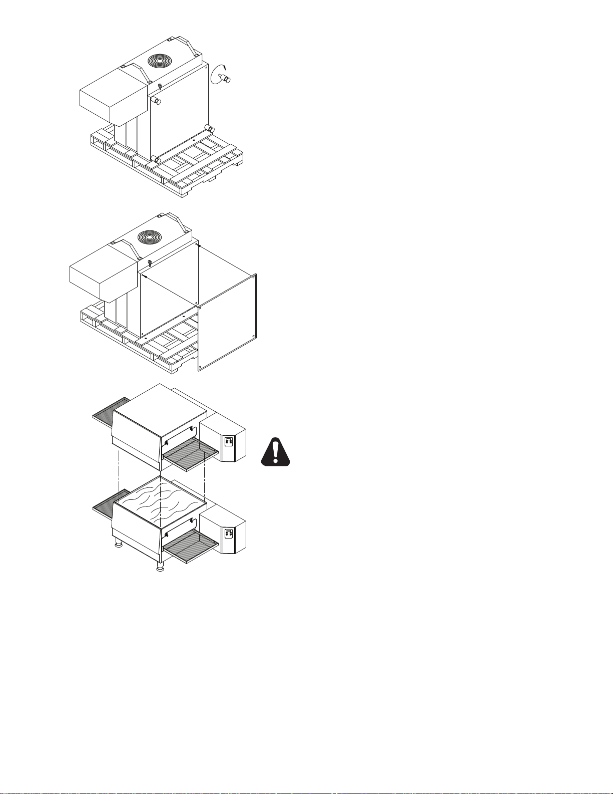
STACKING INSTRUCTIONS
The following instructions should be followed when stacking
more than one unit.
Single Oven (or Bottom) Cart Install:
1. Remove door, conveyor, and nger assemblies.
2. Unbolt unit from shipping crate (2 bolts).
3. Turn unit on front as shown.
4. Thread the four legs into the bottom of the oven.
5. CAREFULLY lift oven upright.
Stacked Oven Install Preparation:
1. Remove door, conveyor, and nger assemblies.
2. Unbolt unit from shipping crate (2 bolts).
3. Turn unit on front as shown.
4. Remove top of lower oven (4 screws total, 2 each front and rear)
and bolt to stacked oven base using 3/8 - 16 bolts.
5. Place top oven on lower unit and re-attach with screws for top of
lower oven.
OPERATING INSTRUCTIONS
DO NOT ATTEMPT TO OPERATE THE OVEN until connection of
utility service and installation has been fully inspected (start-up checkout) by an authorized service technician or a Star Service Technician
in order to assure the oven is properly installed and in working order.
The warranty becomes effective upon verication of proper
installation.
CAUTION
DO NOT WORK AROUND THE CONVEYOR BELT
WITH LONG HAIR, LOOSE CLOTHING, OR DANGLING
JEWELRY. GETTING CAUGHT IN THE BELT COULD
RESULT IN DISMEMBERMENT OR FATAL INJURY.
Unless specied otherwise, conveyor travel is factory set for left to right operation when facing the
front of the oven. If a direction change is required, refer to "DISPLAY INFORMATION," section 3 for
instructions on how to program the controller for a direction change. In addition, the conveyor belt
must be changed to travel in the new direction.
SAFETY OPERATING INSTRUCTIONS
The information contained in this section is provided for the use of qualied operating personnel.
Qualied operating personnel are those who have carefully read the information contained in this
manual, are familiar with the functions of the oven and/or have had previous experience with the
operation of the equipment described. Adherence to the procedures recommended herein will assure
the achievement of optimum performance and long, trouble-free service.
7
Please take time to read the following safety operating instructions. They are the key to the
®
switch to the"OFF" position and wait five minutes.
4) After five seconds, the new numbers will be saved and the oven
decrease TIME or TEMPERATURE. Hold button down for
3) Press the up button (
) to increase or the down button (
) to
hold for four seconds until TIME display goes blank.
1) Press the up and down buttons (
) at the same time,
faster display changes.
will display new settings.
and TEMPERATURE.
2) Press the enter button ( ) to switch between TIME
Adjusting TIME and TEMPERATURE:
After five minutes, retry.
ON
OFF
If burner does not lght in one minute push the power
Push power switch "ON".
To Start:
"HEAT" LIGHT
successful operation of your Ultra-Max Conveyor Oven.
General Safety Tips:
SAFETY TIPS
For your safety, read before operating.
If you smell gas:
1. DO NOT try to light any appliance.
2. DO
3. Use an exterior phone to call your gas supplier
4.
In the event of a power failure:
1. Turn all switches off.
2. DO
NOT touch any electrical switches.
immediately.
If you cannot reach your gas supplier, call
the re department.
NOT attempt to operate the oven until
the power is restored.
1. If the oven needs to be moved for any reason,
the power must be disconnected from the
unit before doing so.
2. DO NOT remove the control box cover unless
the oven is unplugged.
OPERATION
To turn the oven on:
1. Push the power switch to "ON."
2. After the fan begins to build pressure, the
pressure switch will provide power to the
control board to engage the heating element
contactor. You should hear an initial "click"
from the contactor as it begins to heat.
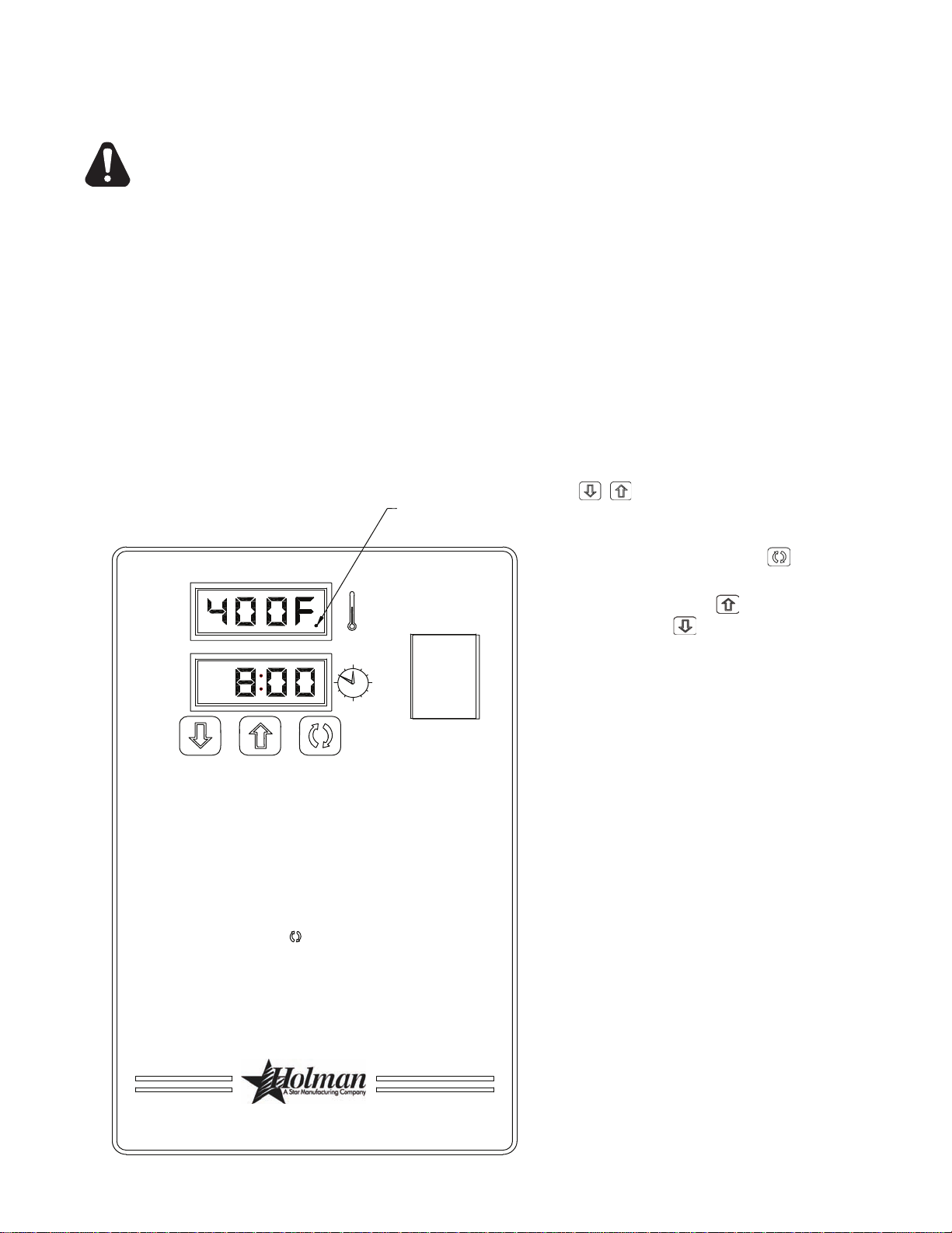
To adjust the time and temperature:
1. Press the DOWN and UP arrows
( ) at the same time. Hold for
four seconds until the TIME display goes
blank.
2. Press the ENTER button (
) to switch
between TIME and TEMPERATURE.
3. Press the UP arrow (
) to increase or the
DOWN arrow ( ) to decrease the TIME or
TEMPERATURE. Hold either button down
for faster display changes.
4. After ve seconds, the new numbers will
be saved and the oven will display the new
settings.
To turn the oven off:
1. Push the power switch to "OFF." The oven
is equipped with a cool-down feature for
motor shaft and bearing protection. This
enables the blower motor(s) to run regardless
of the controller status. The blower(s)
continue to run until the oven cools to a safe
temperature.
8

DISPLAY INFORMATION
When operating the oven, there are three levels of access:
1. Store Level - General employees would know these functions and how to change them. While the
oven is running, enter this mode by holding the DOWN and UP arrows ( ) simultaneously for
four seconds. The TIME display goes blank and the TEMP setpoint is displayed. Adjust with the
DOWN or UP arrows. The ENTER button ( ) toggles between TIME and TEMP. The parameter
that can be adjusted is displayed, the other is blank. When TIME and TEMP are adjusted as
needed, wait ve seconds and SAVE is displayed. The values are accepted and the controller
begins controlling to these new values. The conveyor continues to operate at the same speed
until a new value is accepted. The temperature control output should be OFF during changes.
2. Manager Level - This is a lock so that TIME and TEMP cannot be changed even at
the Store Level. While the oven is running, enter this mode by holding the DOWN and
UP arrows simultaneously for 4 seconds. The TIME display goes blank and the TEMP
setpoint is displayed. Release the UP arrow and continue to hold the DOWN arrow for
an additional 4 seconds. The TEMP display shows LOC as the TIME display shows
nO, which indicates that the TIME/TEMP parameters can be changed after reaching the
STORE level. yES indicates that the parameters cannot be changed even after entering
the STORE level. The LOC setting can be toggled using the ENTER button (
).
ADDITIONAL FUNCTIONS
The conveyor belt direction and the temperature display can be changed on the conveyor oven by
a qualied technician. To change the belt direction, the technician must reverse the motor direction
and rotate the conveyor belt for proper oven function. A technician can also change the temperature
display from Fahrenheit to Celsius. These changes can be made by the technician during the startup/check-out or at a later date.
ERROR CODES
Error codes will display as ashing text messages for diagnostic purposes. Any temperature or
thermocouple error should turn the temperature output OFF and leave the conveyor running at the
same speed. The belt error should turn the temperature output OFF. The speed error should display
when the motor is unable to settle at the chosen speed. This might occur if a fast speed is chosen
that the motor is unable to spin fast enough to achieve. The speed signal output will remain the same
but the display will ash the error message.
9

BAKE TIME VERSUS TEMPERATURE
BAKE vs. DELIVERY TIME
Time to Delivery changes with product
but Bake Time remains constant
at a steady conveyor speed.
24 (BAKE)
32 (DELIVERY)
40 (DELIVERY)
6:00 (BAKE)
8:00 (DELIVERY)
10:00 (DELIVERY)
1. Bake time is actually conveyor speed and is dened as the time the product is actually in the oven.
This is measured by noting the time when the leading edge of the product enters the oven and
the time the leading edge of the product leaves the oven. This is adjusted by using the conveyor
speed controller.
2. Bake temperature is adjusted by changing the setpoint of the temperature controller to the
desired bake temperature. When the oven reaches the desired temperature, the red dot in the
lower right corner of the temperature display will turn off and on as the controller maintains the
temperature.
3.
When establishing a bake time and temperature for a given product, the general rule shall be as
the bake time increases the bake temperature decreases and the reverse is also true; increase
temperature, decrease time. However, there are limits to the above rule. Going to extremes
will result in a burnt exterior and raw interior or it will result in a very light color but over-baked
product.
4.
Once a good bake has been established, the ne adjustments should be made by holding either
the bake time or bake temperature constant, then varying the other.
CONVEYOR SPEED
Bake Time (Conveyor Speed) - As stated previously, bake time (conveyor speed) is dened as the
amount of time elapsed between the time the leading edge of the product enters the oven and the
leading edge of the product exits the oven. Bake time is controlled by adjusting the digital speed
controller. The setting on the control panel indicates the actual bake time.
Bake time will be the same for any size product.
TIME OF DELIVERY
The time of delivery is the amount of elapsed time between the period when the leading edge of the
product enters the oven and the trailing edge of the product is fully discharged and is ready to be
delivered to the customer.
Time of delivery changes if the product size changes.
Tip: Train yourself not
to pull the product out
of the oven when the
leading edge comes
out. Always wait until
the entire product has
passed under the air
nozzle holes - the
product needs this time
to fully bake.
10

CLEANING INSTRUCTIONS
Follow this recommended cleaning schedule for proper oven performance:
CAUTION
DISCONNECT THE POWER SUPPLY BEFORE SERVICING OR CLEANING THIS OVEN.
SAFEGUARD THE POWER SO IT CANNOT BE ACCIDENTALLY RESTORED. FAILURE TO DO SO
COULD RESULT IN DISMEMBERMENT, ELECTROCUTION, OR FATAL INJURY. THERE IS MORE
ONE POWER SUPPLY CONNECTION POINT WHEN OVENS ARE STACKED, SO MAKE
THAN
SURE THAT ALL SWITCHES ARE IN THE OFF POSITION BEFORE CLEANING OR MAINTENANCE.
No electrical components should be subjected to moisture. It is therefore important that the oven is wiped
down carefully. NEVER throw buckets of water over the oven or subject it to pressure washing from a
hose or a pressure spray. If water or other liquid is spilled on the oven, make sure that none of it has
entered the control box area before switching the oven ON. If in doubt, call your service company.
CAUTION
Adhere to the following warnings when cleaning or maintaining your conveyor oven:
1. The oven must be cool. Do not use power cleaning equipment, steel wool, or wire brushes on
stainless steel surfaces.
2. Do not use a caustic or an alkaline base cleaner on the interior of the oven.
This will ruin the aluminized nish of the oven interior.
3.
When using cleaning solutions, be sure they meet local and national health standards.
DAILY
1. Clean the conveyor belt using a nylon brush. Allow any foreign material to drop into the crumb
pans.
2. Empty and clean the crumb pans. Use a hot water and detergent mix.
Rinse
with clean water.
EVERY MONTH
1. Brush and clean the guard on the motor cooling fan.
2. Unplug the oven.
3. Remove the crumb pans.
4. Remove the conveyor assembly.
5. Unlatch and remove the front door. First remove all Baffles then Finger Assemblies.
See instructions next page.
Clean the oven interior with an appropriate oven cleaner.
6.
7. Clean the conveyor assembly, crumb pans, and other removable components.
Wash in a hot water, detergent mix and rinse with clean water. For difcult cleaning areas, use a
heavy-duty
8. Move the oven and clean under it. Be careful not to damage the oven's electrical cord or plug when
moving.
9.
Reassemble the oven, being certain to include all Finger Assemblies and the Upper & Lower
Bafes.
de-greaser or oven cleaner.
Be certian the Lower Bafe Flange is properly positioned behind the Rear Oven Wall, as well
as the Upper Bafe is in position against the Upper Bafe Seat, as shown.
EVERY TWELVE MONTHS
A factory authorized service person should:
1. Open and clean the inside of the control box.
2. Check and tighten all electrical components.
If maintenance is required, contact your local service company, a factory representative, or
Star Manufacturing.
11

1
2
3
IL1190
4
LOWER BAFFLE
UPPER BAFFLE
Removing Finger Assemblies
1. Once cooled, REMOVE conveyor assembly and door.
2. Life up and remove Upper & Lower Bafes as shown in Step 1.
3. Slide Finger Assembly out of unit as shown in Step 2.
4. Lift Assembly apart as shown in Step 3. and wash in a hot water, detergent mix and rinse
ith clean water. For difficult cleaning areas, use a heavy-duty de-greaser or oven
w
cleaner.
Reassemble Finger Assemblies
1. Reassemble nger assemblies and install in unit.
2. Properly install Bafes as shown in Step 4.
CAUTION
BE CERTAIN THE LOWER BAFFLE IS PROPERLY INSTALLED BEHIND THE REAR PANEL
SO NOT TO INTERFERE OR DAMAGE CONVEYOR ASSEMBLY.
3. Reinstall conveyor & door assembly, and test unit for proper operation.
Bafe & Finger Removal / Installation
12
 Loading...