

Page 1
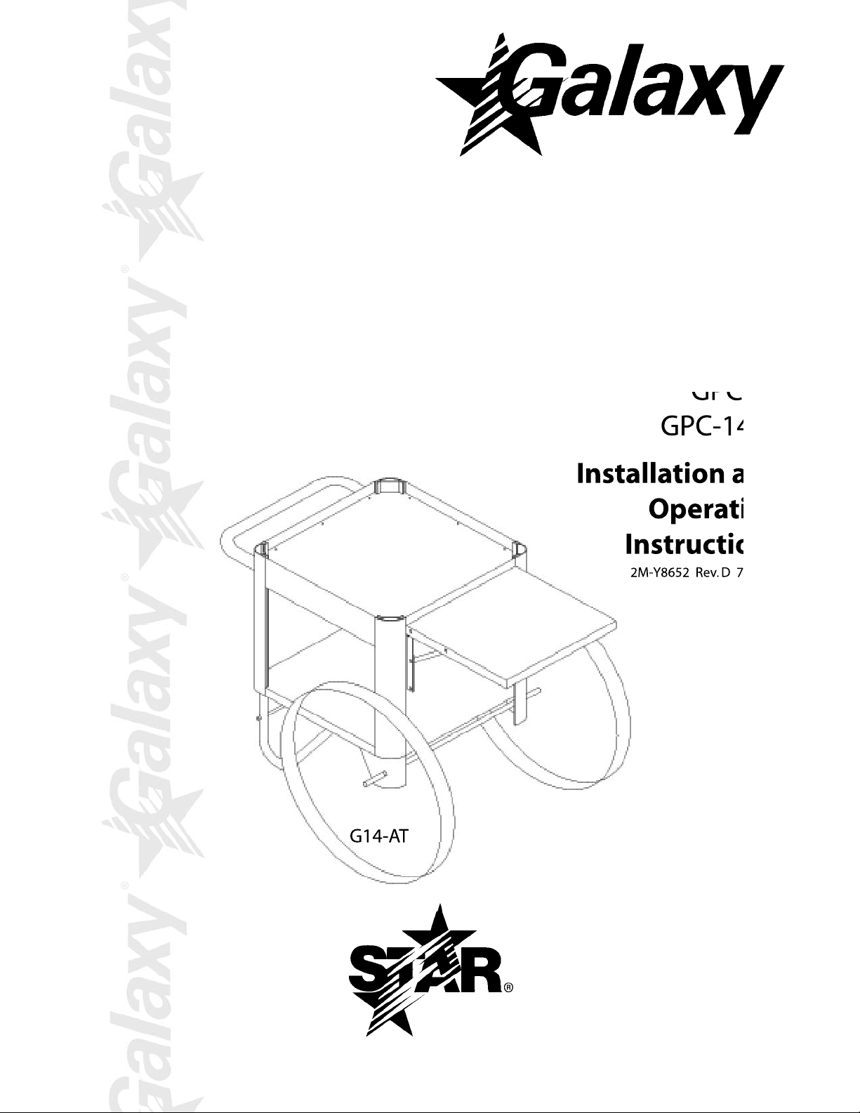
POPCORN
CARTS
MODELS
GPC-8
GPC-8AT
GPC-14
GPC-14AT
®
G14-AT
Installation and
Operation
Instructions
2M-Y8652 Rev. D 7/14/05
1
Page 2

SAFETY SYMBOL
Using any part other than genuine Star factory supplied parts relieves the
manufacturer of all liability.
Star reserves the right to change specifi cations and product design without
notice. Such revisions do not entitle the buyer to corresponding changes,
improvements, additions or replacements for previously purchased
equipment.
Due to periodic changes in designs, methods, procedures, policies and
regulations, the specifi cations contained in this sheet are subject to change
without notice. While Star Manufacturing exercises good faith efforts to provide
information that is accurate, we are not responsible for errors or omissions
in information provided or conclusions reached as a result of using the
specifi cations. By using the information provided, the user assumes all risks in
connection with such use.
These symbols are intended to alert the user to the presence of
important operating and maintenance instructions in the manual
accompanying the appliance.
RETAIN THIS MANUAL FOR FUTURE REFERENCE
NOTICE
MAINTENANCE AND REPAIRS
Contact your local authorized service agent for service or required maintenance. Please record the model
number, serial number, voltage and purchase date in the area below and have it ready when you call to
ensure a faster service.
Model No.
Serial No.
Voltage
Purchase Date
Authorized Service Agent
Reference the listing provided with the unit
or
for an updated listing go to:
Website: www.star-mfg.com
E-mail Service@star-mfg.com
Telephone: (800) 807-9054 Local (314) 781-2777
The Star Service Help Desk
Business 8:00 am to 4:30 p.m. Central Standard Time
Hours:
Telephone: (800) 807-9054 Local (314) 781-2777
Fax: (800) 396-2677 Local (314) 781-2714
E-mail Parts@star-mfg.com
Service@star-mfg.com
Warranty@star-mfg.com
Website: www.star-mfg.com
Mailing Address: Star Manufacturing International Inc.
10 Sunnen Drive
St. Louis, MO 63143
U.S.A
2
Page 3

INSPECTION & ASSEMBLY
UNCRATING & INSPECTING
Carefully unpack the unit and inspect it for any damage.
Check the parts against the attached parts list before starting any assembly. Refer to
drawing SK1246 for exploded view of cart.
CART HANDLE ASSEMBLY
(see SK1245)
Assemble left and right handle brackets (#6 & 7) to handle rod (#8) using (2) 1/4"-20x3/8"
machine screws (#11a) and (2) 1/4" lockwashers (11c).
o
NOTE: 90
Mount completed handle assembly to cart body (#1) using (4) 1/4-20x3/8 machine screws
(11a), (4) 1/4" lockwashers (#11c) and (4) 1/4-20 acorn nuts (#11b).
LEG ASSEMBLY
Insert one end of tie rod assembly (#10) through hole in side of (1) support leg (#9) and lock
in position with (1) 5/16" push nut (#11h).
Repeat above step for opposite leg.
CAUTION
fl anges should be turned to the inside (facing each other).
DAMAGE MAY OCCUR TO PUSH NUTS IF REMOVAL IS ATTEMPTED
AFTER THEY ARE IN POSITION.
LEG AND WHEEL ASSEMBLY (TO BODY)
Install completed leg assembly to the bottom of the body assembly (#1) with (4) 1/4-20x3/8
machine screws (#11a) and (4) 1/4" lockwashers (#11c). Install (2) axle support brackets
(#4) to the bottom of the body assembly (#1) with (8) 1/4-20x3/8" machine screws (#11a)
and (8) 1/4" lockwashers (#11c).
Insert axle (#3) through both axle support brackets. Insert (1) 3/32x3/4" cotter pin (#11f)
through hole near each end of the axle rod and spread cotter pin legs to prevent loss of
cotter pin.
NOTE: Cotter pins should be on the inboard side of each axle bracket.
Install (1) axle sleeve (#11d) followed by (1) 1/2" fl at washer (#11e) to each end of axle rod.
Install (1) wheel (#2) followed by (1) 1/2-13 locknut (#11g) to each end of axle rod.
NOTE: Grip axle rod with vise grips, channel lock pliers or pipe wrench near inboard
side of axle rod support since any marking of paint or plating will be hidden by the
bracket.
DROP SHELF INSTALLATION
Assemble drop shelf assembly (#5) to body (current construction level) using (4) 1/4-20x3/8"
machine screws (#11a), (4) 1/4 lockwashers (#11c) and (4) 1/4-20 acorn nuts (#11b).
Adjustment can be made left or right, up or down before nuts are fully tightened.
3
Page 4

INSTALLATION OF MACHINE TO CART
PREPARATION
Remove kettle from popcorn machine and set it aside out of the way.
Carefully lay the popcorn machine down on it's back or sides, on a smooth, fl at surface.
Note: You may want an assistant for this step.
CAUTION
DO NOT LAY THE POPCORN UNIT ON THE DOORS OR ON AN
OBSTRUCTED OR UNEVEN SURFACE AS GLASS BREAKAGE MAY
OCCUR.
Remove the (4) rubber plugs from the phenolic feet. Using a phillips screwdriver, remove (1)
screw from each foot and replace it with a 10-24x2" collared stud (#11i) in the same position
(see SK1245).
NOTE: Approximately 3/8" of thread will protrude from the bottom of each foot.
INSTALLATION
Using an assistant, raise the popper to it's upright position. Use caution not to bend
or damage the threaded studs.
Move cart close to the popper with the open shelves facing in the same direction as
the doors on the popper.
Insert bushing sleeve (11L) in plastic bushing already protruding through the top
plate of the cart.
Lace cord set through the sleeve and bushing from top to bottom as far as it will go.
With your assistant's help, carefully pick up the popcorn machine from the bottom. DO NOT
pick up the machine by grasping the doors, top or other "convenient" hand holds. NON
STRUCTURAL PARTS MAY BE DAMAGED. Place the popcorn machine on the cart with
the (4) studs near the mounting holes in the top plate of the base. Be careful not to pinch
your hand or fi ngers between the two units.
NOTE: Placing the popper slightly askew (catty corner) will provide clearance for
your hands.
Carefully slide the popper into position on the cart until the (4) studs drop through
the mounting holes in the top plate. Do not allow the popper to drop too heavily, try
to ease it into position one stud at a time. KEEP FINGERS CLEAR.
Place (1) fl atwasher (11k) and (1) 10-24 acorn nut (11j) on each stud protruding
through the top plate of the cart and tighten.
Replace the kettle assembly, plug in the unit and check for proper operation.
This completes the installation procedure. Occassionally check the mounting nuts
since movement may cause them to loosen. Re-tighten as necessary.
MAINTENANCE AND REPAIRS
Contact the factory, a service representative or a local
service company for service or required maintenance.
4
Page 5

Visit our Website at: www.star-mfg.com Email: service@star-mfg.com
THOROUGHLY INSPECT YOUR UNIT ON ARRIVAL
This unit has been tested for proper operation before leaving our plant to insure delivery of your unit in perfect condition. However, there are instances in which the
unit may be damaged in transit. In the event you discover any type of damage to your product upon receipt, you must immediately contact the transportation company
who delivered the item to you and initiate your claim with same. If this procedure is not followed, it may affect the warranty status of the unit.
LIMITED EQUIPMENT WARRANTY
All workmanship and material in Star products have a one (1) year limited warranty on parts & labor in the United States and Canada. Such warranty is limited to the
original purchaser only and shall be effective from the date the equipment is placed in service. Star's obligation under this warranty is limited to the repair of defects
without charge, by the factory authorized service agency or one of its sub-agencies. Models that are considered portable (see below) should be taken to the closest Star
service agency, transportation prepaid.
> Star will not assume any responsibility for loss of revenue.
> Holman Brand equipment warranty repair must be pre-authorized before any work is performed.
> On all shipments outside the United States and Canada, see International Warranty.
* The warranty period for the JetStar series six (6) ounce popcorn machines is two (2) years.
* The warranty period for the Chrome-Max Griddles is fi ve (5) years on the griddle surface. See detailed warranty provided with unit.
* The warranty period for Tefl on/Dura-Tec coatings is one year under normal use and reasonable care. This warranty does not apply if damage occurs to
Tefl on/Dura-Tec coatings from improper cleaning, maintenance, use of metallic utensils, or abrasive cleaners. This warranty does not apply to the
“non-stick” properties of such materials.
> This warranty does not apply to "Special Products" but to regular catalog items only. Star's warranty on "Special Products" is six (6) months on parts
and ninety (90) days on labor.
> This warranty does not apply to any item that is disassembled or tampered with for any purpose other than repair by a Star Authorized Service Center or
the Service Center's sub-agency.
> This warranty does not apply if damage occurs from improper installation, misuse, wrong voltage, wrong gas or operated contrary to the Installation and
Operating instructions.
> This warranty is not valid on UltraMax Conveyor Ovens unless a "start-up/check-out" has been performed by a Factory Authorized Technician.
PARTS WARRANTY
Parts that are sold to repair out of warranty equipment are warranted for ninety (90) days. The part only is warranted. Labor to replace the part is chargeable to the
customer.
SERVICES NOT COVERED BY WARRANTY
1. Travel time and mileage rendered beyond the 50 mile radius limit
2. Mileage and travel time on portable equipment (see below)
3. Labor to replace such items that can be replaced easily during a daily cleaning
routine, ie; removable kettles on fryers, knobs, grease drawers on griddles, etc.
4. Installation of equipment
5. Damages due to improper installation
6. Damages from abuse or misuse
7. Operated contrary to the Operating and Installation Instructions
8. Cleaning of equipment
9. Seasoning of griddle plates
PORTABLE EQUIPMENT
Star will not honor service bills that include travel time and mileage charges for servicing any products considered "Portable" including items listed below. These products should be taken to the Service Agency for repair:
* The Model 510FD Fryer.
* The Model 526TOA Toaster Oven.
* The Model J4R, 4 oz. Popcorn Machine.
* The Model 526WOA Warming Oven.
* The Model 518CMA & 526CMA Cheese Melter.
* The Model 12MC & 15MC & 18MCP Hot Food Merchandisers.
* The Model 12NCPW & 15NCPW Nacho Chip/Popcorn Warmer.
* All Hot Dog Equipment except Roller Grills & Drawer Bun Warmers.
* All Nacho Cheese Warmers except Model 11WLA Series Nacho Cheese Warmer.
* All Condiment Dispensers except the Model HPDE, & SPDE Series Dispenser.
* All Specialty Food Warmers except Model 130R, 11RW Series, and 11WSA Series.
* All QCS/RCS Series Toasters except Model QCS3 & RCS3 Series.
The foregoing warranty is in lieu of any and all other warranties expressed or implied and constitutes the entire warranty.
FOR ASSISTANCE
Should you need any assistance regarding the Operation or Maintenance of any Star equipment; write, phone, fax or email our Service Department.
In all correspondence mention the Model number and the Serial number of your unit, and the voltage or type of gas you are using.
10. Voltage conversions
11. Gas conversions
12. Pilot light adjustment
13. Miscellaneous adjustments
14. Thermostat calibration and by-pass adjustment
15. Resetting of circuit breakers or safety controls or reset buttons
16. Replacement of bulbs
17. Replacement of fuses
18. Repair of damage created during transit, delivery, &
installation OR created by acts of God
ALL:
* Pop-Up Toasters
* Butter Dispensers
* Pretzel Merchandisers
* Pastry Display Cabinets
* Nacho Chip Merchandisers
* Accessories of any kind
* Sneeze Guards
* Pizza Ovens
* Heat Lamps
* Pumps
Part# 2M-4497-2 05/05 RMS
Page 6

567
Page 7

Page 8

PARTS LIST
MODEL
GPC-8, GPC-8AT, GPC-14, GPC-14AT
Number
Key
Number
1 1 BODY ASSEMBLY
2 2B-Y8574 2 WHEELS - STAINLESS
2 2B-Y4752 2 WHEELS - ANTIQUE
3 C3-Y8463 1 AXLE - 8 OZ. STAINLESS
3 C3-Y8576 1 AXLE - 8 OZ. ANTIQUE
3 2A-Y8526 1 AXLE - 14 OZ. STAINLESS
3 2A-Y8595 1 AXLE - 14 OZ. ANTIQUE
4 C3-Y8444 2 AXLE SUPPORT BRACKET - STAINLESS
4 C3-Y8583 2 AXLE SUPPORT BRACKET - ANTIQUE
5 C3-G8041 1 DROP SHELF ASSEMBLY - 8 OZ. STAINLESS
5 C3-G8055 1 DROP SHELF ASSEMBLY - 8 OZ. ANTIQUE
5 C3-G8043 1 DROP SHELF ASSEMLBY - 14 OZ. STAINLESS
5 C3-G8052 1 DROP SHELF ASSEMBLY - 14 OZ. ANTIQUE
5a C3-19122 1 SHELF SUPPORT ASSEMBLY R.H.
5b C3-19123 1 SHELF SUPPORT ASSEMBLY L.H.
6 C3-Y4737 1 HANDLE BRACKET - LEFT
7 C3-Y4736 1 HANDLE BRACKET - RIGHT
8 C3-G8063 1 HANDLE ROD WITH NUT INSERTS - 8 OZ.
8 C3-G8064 1 HANDLE ROD WITH NUT INSERTS - 14 OZ.
9 2V-Y8445 2 SUPPORT LEGS - STAINLESS
9 2V-Y8575 2 SUPPORT LEGS - ANTIQUE
10 C3-G8039 1 TIE ROD ASSEMBLY - 8 OZ. STAINLESS
10 C3-G8049 1 TIE ROD ASSEMBLY - 8 OZ. ANTIQUE
10 C3-G8042 1 TIE ROD ASSEMBLY - 14 OZ. STAINLESS
10 C3-G8051 1 TIE ROD ASSEMBLY - 14 OZ. ANTIQUE
11a 2C-Y8767 22 1/4-20 x 3/8 MACHINE SCREW
11b 2C-2581 8 1/4-20 ACORN NUT
11c 2C-1823 22 1/4" SPLIT LOCKWASHER
11d 2V-Y8464 2 AXLE SLEEVE
11e 2C-H2019 2 1/2" FLATWASHER
11f 2A-5401 2 3/32 x 3/4 COTTER PIN
11g 2C-Y4755 2 1/2-13 LOCK NUT
11h 2C-Y8568 2 5/16 PUSH NUT - RED
11h 2C-Y8569 2 5/16 PUSH NUT - BLACK
11i 2C-Y8570 4 10-24 x 2" COLLARED STUD
11j 2C-2559 4 10-24 ACORN NUT
11k 2C-1811 4 1/4" I.D. x .620 DIA. FLAT WASHER
11l 2V-Y8648 1 BUSHING SLEEVE
Part
Number
Per
Unit
Description
IMPORTANT: WHEN ORDERING, SPECIFY VOLTAGE OR TYPE GAS DESIRED PAGE
INCLUDE MODEL AND SERIAL NUMBER-MINIMUM PARTS ORDER-$5.00 OF
Some items are included for illustrative purposes only and in certain instances may not be available.
Star Manufacturing International, Inc.
1
1
 Loading...