

Page 1

wireless unit
Revision No.2
Oc to be r 2016
R6
Page 2

StarLine R6
General
The StarL ine R6 wireless unit protec ts your vehicle agai nst theft
by block ing an engine and pre vents from intrud er access to
underho od compartme nt by means of a hood loc k intelligent
control.
StarLine R6 ma y only be used in combi nation with the 6th
Generatio n StarLine secu rity sys tems (X96, M96, E96, S96 etc.)
Data bet ween the main unit of a s ecurity syst em and StarLine R6
are trans ferred via the Blu etooth Smart (BLE ) protocol using a dat a
interception protection algorithm while device registration.
Benets of StarLine R6 underhood unit:
• waterproof housing;
• sm all dimensions of the unit allow s to hide it in a hard to reach
place of engine compartment;
• engine temperature monitoring via an external sensor
supplie d within the packa ge;
• integrated motion sensor;
• ho od lock and engin e lockout intellige nt control in case of a
lost conn ection with the main unit of a se curity syste m.
2
Page 3
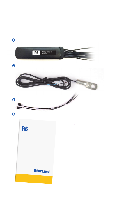
Delivery package
Main unit with wires.
Temperature sensor.
Plastic br ace (2 pcs.)
Installation manual.
INSTALLATION
MANUAL
Installation manual
UNDERHOOD UNIT
3
Page 4

StarLine R6
Specifications
Parameter Value
Input vol tage, V 8
Current consumption, mA
Insulation class
Maximu m current at LOCK and UNLO CK
outputs, A
Maximum permitted switched current via relay
contac ts, A
Operating temperature range, °С –40 .. . +85
Temperature sensor measuring range, °С – 40 ... +150
Control pu lse duration of hoo d control, s 0,8
Dimensions, mm
– 18
1,2
IP67
12
10
94×24×13
4
Page 5

Installation manual
Operation description
Operation modes
The StarLine R6 wireles s relay unit has two op eration modes:
• no rmal;
• standal one.
Normal mode
In normal m ode StarLine R6 communic ates with the main uni t and
receives i ts contro l commands for engin e block , hood lo ck, and
the alarm siren. The StarLine R6 monitors the state of the hood,
ignition, engine t emperature and tr ansfers these dat a to the main
unit.
Standalone mode
The StarLine R6 will turn to the st andalone mode in c ase of
communic ation los s with the ma in unit for m ore than 30 s econds
indicating this with a alarm siren signal.
The StarLine R6 standalone mode has two submodes:
• armed
StarLine R6 enters this subm ode, if the security syst em has
been arm ed prior to the commu nicatio n loss. Af ter the alarm
siren sto ps StarLine R6 will lo ck the vehicle hood .
StarLine R6 independently controls engine blocking, hood
lock, and an alarm siren.
• disarmed
StarLine R6 enters this subm ode, if the security syst em has
been dis armed prior to the co mmunication loss .
Engine blocking, hood lock and alarm siren control is not
performed in this mode.
When conn ection with the m ain unit of securit y system is
recovered, StarLine R6 will automatic ally return to the
normal operation mode.
5
Page 6

StarLine R6
Engine blocking
Normal mode
In the norm al opera tion mod e StarLine R6 blocks an en gine by a
command of t he main unit.
Standalone mode
In the stan dalone m ode, an en gine can b e blocked by either of the
following events:
• when the igniti on is turned on
Engine wi ll be blocked in a mom ent of ignition is tur ned on.
• when a vehicle sta rts moving (if the IG N wire is not connect ed)
An engine w ill be blo cked for 30 s econds af ter a vehi cle star ts
moving, t hen the StarLine R6 will unlock an eng ine until the nex t
attempt t o move the veh icle. Af ter three attempt s StarLine R6
will block the engine until connection with security s ystem is
recovered.
Control of a hood lock
• In the normal mo de hood loc k control is made wi th an alarm main
unit commands.
• In the standalone mode if the syst em has been armed b efore, the
StarLine R 6 will lock the ho od whenever com munication wit h the
main unit is l ost.
6
Page 7

Installation manual
Alarm siren control
In the norma l mode alarm siren control is made with an alarm main
unit ommands.
In the standalone mode StarLine R6 independently controls an alarm
siren.
The StarLine R6 turns on so und alarm in followi ng cases:
• communicat ion with an a larm main u nit is lost (30 s long
intermittent alarm siren sound);
• ei ther of the followi ng security zon es is disturbed:
• ho od, moti on senso r (30 s long cont inuous alarm siren
sound);
• ig nition is On (continuo us alarm siren sound u ntil ignition
is turned O ).
7
Page 8

StarLine R6
General installation requirements
StarLine R6 nderhood uni t is design ed for ins tallati on on vehicl es
with 12 V voltage .
StarLine R6 should be inst alled under the vehicle hood. Mount th e
unit in a hidden place so that it woul d not conta ct movin g part s of
the vehicl e. Fasten the housing wi th plastic braces .
Connection of power circuits
Power suppl y is connec ted usin g two wire s: +12 V (BAT wire) and
“ground” (GND wire).
First of all, connec t the “groun d” wire. Fo r connec tion to th e
“ground” us e the “ground” bo lt or nut. At that, cr imp the terminal o n
the wire fo r the correspon ding fastener d iameter. The “groun d” wire
shall not b e connected to t he body by means o f a self-tappi ng screw.
The connection point should be treated with corrosionpreventive
compound.
In order to co nnect +12 V (the BAT wire), you wi ll need to use regu lar
circuits o f the vehic le with cons tant +12 V voltage and a mi nimum
cross sec tion of 2 mm
BAT wire should b e connec ted via th e fuse incl uded in th e deliver y
set.
2
, or connec t direc tly to the c ar’s batt ery. The
8
Page 9

Wiring diagram
Connection diagram
Hood limit
switch
Installation manual
sensor
Temperature
Power 20 A
Alarm siren
Ignition
INPUT
orange-grey
brown
NO
black-yellow
COM
BAT
red
Engine blocking circuit
IGN
yellow
blue
green
LOCK
UNLOCK
Hood lock drive
OUTPUT
grey
EXT
GND
black-white
black
orange
NC
9
Page 10

StarLine R6
Description of external outputs
Diagram of external outputs
NO
NC
COM
UNLOCK
LOCK
brown
orange
black-yellow
blue
green
V
V
V
Designation of external outputs
Marking Assignment
GND Ground (-)
BAT Powe r (+)
IGN Ignition (+)
NO Normall y open contact of r elay (NO)
NC Normall y closed contact o f relay (NC)
COM Common relay contact
UNLOCK Hood lo ck open pulse
LOCK Hood lo ck close pulse
INPUT Hood lim it switch input (-)
OUTPUT Ou tput to the alarm sire n (+)
EXT Temperature sensor input
10
orange-grey
black-white
black
red
yellow
grey
INPUT
EXT
GND
BAT
IGN
OUTPUT
Page 11

Installation manual
IGN wire – input for conn ectio n to the vehicle igniti on. The IGN
wire shall h ave the pote ntial of +12 V during ignit ion switc h-on and
engine operation.
NO, NC, COM wires – ou tputs of t he built-in elec tromech anical
relay are con necte d to an engin e block ing circui t. Block ing can b e
perfo rmed using norma lly closed (COM and NC) and normally open
(COM and NO) contac ts. Wh en wiring t hese circ uits, it is n ecessa ry
to obser ve the length and cros s-sec tion of wir es used for switchin g,
becaus e switched cur rent can be signi cant. If cur rent in the block ed
circuit ex ceeds 10 A, an auxiliar y external rel ay should be used.
Crankshaft
position
sensor
R6 NO contacts
Example of using NO contacts for blocking
87
85
(+)
CommonN C
(-)
86
30
Connection of external blocking relay
Engine
control
R6 NO contactsIgnition
COM
Engine blocking circuit
unit
NO
11
Page 12

StarLine R6
UNLOCK , LOCK wi res – power output s for contro lling the h ood
lock ele ctric al drive. The outputs are buil t according to the power
scheme (th e maximu m output cu rrent is 12 A), there fore no
additio nal power m odules are require d for loc k control. W henever
the hood is u nlocked, a +12 V pulse is genera ted at the UNLOCK wire
for 0.8 s. W henever the hood is l ocked, a +12 V pulse is gene rated at
the LOCK wir e for 0.8 s.
Output “Ope n” pulse “Close” pulse
UNLOCK + –
LOCK – +
INPUT wi re – this wire is conne cted to the hood lim it switch, letti ng
the syste m monitor the hood s tatus
OUTPUT wire – alarm siren co ntrol output. T he maximum pe rmitted
current is 2 A . Connec t one of a si ren wires w ith the OUTPUT wir e
and conne ct another wire wi th the “ground”.
EXT wire – temperature senso r input. T he two-wire tem peratur e
sensor sh ould be con necte d to the wire s EXT and GND with a ny
polarity.
12
Page 13

Installation manual
Registering the underhood unit
If a StarLine R6 underhoo d unit was purchased s eparately from t he
securit y system, it must b e registered into t he main unit memor y.
Registration procedure for StarLine R6 unit:
1. Switch igniti on O.
2. Disconn ect the ВАТ, OUTPUT and INPUT wires f rom a car
circuits.
3. Disarm a ve hicle (refer to the se curity system m anual) and
switch Sta rLine securit y system into Device r egistration mo de:
- turn igni tion On;
- press a ser vice (valet) but ton 7 times;
- then 7 but ton LED ashes and 7 sir en sounds will foll ow.
4. Intercon nect th e OUTPUT and INPUT wires o f the
StarLine R6.
5. Connec t power inp uts (B AT and GND wires) to +12V and
ground.
6. In 10 seconds a fter successfu l registration a se curity system
will generate sound signal.
7. Disconnect th e BAT wire from a c ar circuits, then o pen the
OUTPUT and INPUT wires.
8. Check o peration of StarLine R6.
13
Page 14

StarLine R6
The manufacturer reserves the right to modify and
improve the product design and technical features
without prior notice.
Manufacturer:
ScPA “StarLine” LLC,
Komissara Smirnova str., 9,
194044, Saint-Petersburg, Russian Federation
Tel. +7 812 3263333
www.alarmstarline.com
14
Page 15

Installation manual
15
Page 16

StarLine R6
16
 Loading...