

StarLeaf Teamline 5140 Installation Manual

Teamline 5140
Installation Guide
03 January 2019

Contents
Before you install Teamline 5140 4
Prerequisites 4
Create a Skype for Business account 4
Skype for Business requirements 4
Exchange requirements 4
Changing the room display title 5
About the Teamline 5140 system 6
The connectors 6
Dimensions 6
Connecting Teamline 5140 to peripherals 8
Positioning the Teamline 5140 system 8
Connecting network cables 8
Connecting the StarLeaf Touch 8
Connecting the touchscreen to the Teamline system 9
Connecting the camera and microphone 9
Connecting displays and audio 10
Extending cables 10
Connecting power 10
Mounting the Teamline 5140 system 11
Mount dimensions 13
Configuring Teamline 5140 14
Connecting the system to Maestro 14
Configuring the proxy server (optional) 14
Changing system settings 15
Using a static IPaddress 15
Ports and protocols 16
Room system connectivity 16
Outbound 16
Inbound 16
On-premise Skype for Business 2015 or Lync 2013 17
Outbound 17
Teamline systems on external networks 18
Skype for Business Online 18
Outbound 19
Inbound 19
Internal for Teamline 5140 20
Teamline 5140, 03 January 2019 Page 2 of 33

System LED behavior 21
Network port LED 21
Using cameras with Teamline 5140 22
Shelf dimensions 23
Examples of the maximum field of view 23
Installing the VHD-V71 camera 25
Microphone selection, placement,and setup 26
Pinout for StarLeaf microphone cable 27
The connectors and pin positions 27
Cable recommendations for room systems 28
HDMI cables 28
USB cables 28
Camera cables 28
VISCA cable requirements 29
Pinout 29
Teamline 5140 safety and compliance information 31
Installation 31
Ventilation 31
Servicing 31
Power requirements 31
Operating environment 31
Approvals information 32
EU/EEC 32
Legal information 33
Third party software acknowledgments 33
Disclaimers and notices 33
Teamline 5140, 03 January 2019 Page 3 of 33

Before you install Teamline 5140
Before you install Teamline 5140
Before installing the Teamline system, read the Teamline 5140 safety and compliance
information (p31).
Prerequisites
Ensure you have:
n One or two commercial displays that support a 1080p60 input format
Note: Interlaced input is not supported.
n Displays with an audio-output capability and a spare HDMIinput. If the displays have
Game Mode or PC Mode, enable one of these options to reduce media processing
delays and improve video experience
n A camera
n Microphone(s)
Create a Skype for Business account
On the Skype for Business server, create a user account that will be used by your Teamline
system, or you can use an existing account. Make note of the authentication details.
Skype for Business requirements
For on-premise deployments, if the Skype for Business server certificates were issued by a
private certificate authority, ensure you have the certificate of the Root Certificate
Authority and any intermediate certificates. For more information, visit the Microsoft site:
how to export Root Certification Authority Certificates
The Teamline system supports:
n Lync 2010 Server
n Lync 2013 Server
Note: If the deployment is not a Lync 2013 server, ensure that the Lync 2013 user interface is
enabled.
n Skype for Business 2015 Server
n Skype for Business Online
Exchange requirements
Ensure you have a user account or room resource with Calendar enabled, and that it is
linked to a Skype for Business account.
The Teamline system supports:
n Exchange 2010 SP2 Server
n Exchange 2013 Server
n Exchange Online
Teamline 5140, 03 January 2019 Page 4 of 33

Before you install Teamline 5140
Note: Invitation emails to the Teamline system must contain the necessary attachments
for conferencing facilities to function correctly. Otherwise, participants will be unable to
use the Join Now option on the touchscreen. Automatic meeting responses may delete
attachments; ensure automatic responses are configured to keep attachments.
Changing the room display title
The Teamline room display shows the titles of upcoming meetings. The meeting titles
originate from the room's Exchange calendar. If you are using an Exchange resource
account for your room, by default, the organizer's name in the Exchange calendar is
displayed as the meeting title. To change the default display to the meeting title, refer to
this Microsoft article.
Teamline 5140, 03 January 2019 Page 5 of 33
About the Teamline 5140 system
About the Teamline 5140 system
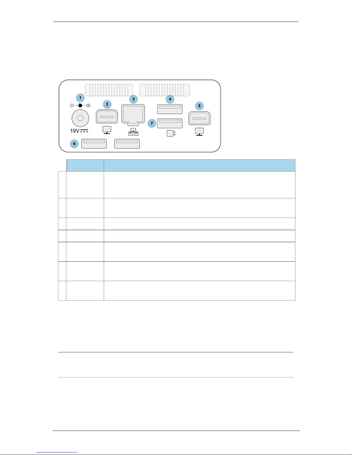
The connectors
The following figure shows the connectors on the rear of the Teamline system:
Connector Description
1
Power
A DC +19V power connector. The system automatically adjusts to the
supply voltage. Use the supplied power cable to connect the system
to the power. Connect all other cables before connecting the power
2
Display 1
Mini display connectors. These connectors output video (1080p60 only)
to the display
3
Network
10/100/1000 Mbit/s auto-sensing Ethernet port. Connect to the network
4
Microphone
USB connector. Connect a StarLeaf microphone
5
Display 2
Mini display connectors. These connectors output video (1080p60 only)
to a second display (if present)
6
USB 2.0
USB 2.0 connectors. If you are using a static USB camera, connect it to
one of these USB 2.0 connectors
7
Camera
(USB 3.0)
USB 3.0 connector. If you are using a PTZ USB camera, connect the
camera cable to the USB 3.0 connector
Dimensions
The Teamline 5140 system is designed so that it doesn't need to be rack mounted;
however, it can be wall mounted or mounted to the back of your display.
Note: If you are using wireless (for example, Miracast) to connect devices to present
content in meetings, ensure the system is not enclosed in a rack or behind a display.
Otherwise, the wireless signal may not function.
Teamline 5140, 03 January 2019 Page 6 of 33

About the Teamline 5140 system
Dimension Metric Imperial
Width 150 mm 5.9 in
Depth 152 mm 5.98 in
Height 57 mm 2.24 in
Teamline 5140, 03 January 2019 Page 7 of 33

Connecting Teamline 5140 to peripherals
Connecting Teamline 5140 to peripherals
What's in the box?
n Teamline 5140 room system
n StarLeaf Touch touchscreen controller
n Wall mounting kit
n Cables
l Power cable
l Ethernet cable
l Two HDMI to HDMI cables (1.8 meters/5.9 feet)
l Patch cable (2 meters/6.6 feet)
l USBA to mini B (2.5 meters/8.2 feet)
n Two Mini DisplayPort to HDMI adaptors
n StarLeaf microphone
n A camera and where applicable, camera cables, mounting kit, and camera power
supply
Positioning the Teamline 5140 system
1. Choose an appropriate installation site:
l The system must be accessible to ensure all cables are easily connected
l Provide ventilation for the system; leave a space of at least 10cm (4 inches) behind,
in front, and to the left and right of the system
l Use a grounded AC power outlet for the system
2. Wall mount the system or place on a firm horizontal surface. For information, refer to
Mounting the Teamline 5140 system (p11).
Connecting network cables
Using an Ethernet cable, connect the Network port on the rear of the system to an
Ethernet switch in your network. The Ethernet port is a 10/100/1000 Mbit/s auto-sensing port
and is set to ‘auto’ by default.
Note: If your network doesn't support automatic detection, you can configure the
network speed manually. On the touchscreen controller that you have connected to the
system, go to settings > networking > network port speed and select 100Mb/s (full).
Connecting the StarLeaf Touch
Using an Ethernet cable, connect the PoE Network port on the rear of the touchscreen to
an Ethernet switch in your network. The Ethernet port is a 10/100/1000 Mbit/s auto-sensing
port and is set to ‘auto’ by default. The touchscreen needs a switch/port that supplies PoE
to function.
Note: The speed and duplex settings at either end of the connection must be identical.
Using non-matching settings causes severe packet loss.
Teamline 5140, 03 January 2019 Page 8 of 33

Connecting Teamline 5140 to peripherals
Connecting the touchscreen to the Teamline
system
Before you can use the StarLeaf Touch for your meetings, you must pair it with the
Teamline system. To do this:
1. Connect the touchscreen to a Power over Ethernet (PoE) enabled port.
2.
On the touchscreen, double-tap to display the settings page.
3.
Tap the networking tab and use the toggle to turn off auto-discovery. The
configuration server field is displayed.
4.
In the configuration server field, enter the MAC address printed on the bottom of the
Teamline system.
The touchscreen will attempt to establish a connection to the Teamline system using IPv6
before the system will establish a connection to the LAN (IPv4). Both the touchscreen and
the Teamline system must be on the same VLAN. In most cases, the VLAN and subnet are
the same. If the touchscreen cannot establish an IPv6 connection to the codec, a failure
message is displayed.
The IPv6 addresses are derived using the MAC address of each device. These addresses
are used to establish a local connection between the touchscreen and the Teamline
system. This is called an IPv6 link local address.
You can pair the touchscreen and Teamline system across different physical switches as
long as they are both on the same VLAN.
Once the touchscreen and Teamline system have successfully paired, the touchscreen
sends the network settings (DHCP or static) to the Teamline system. The Teamline system
establishes an IPv4 address and connection to the corporate LAN. If the Teamline system
cannot establish a connection to the corporate LAN, a failure message is displayed.
However in this case, the touchscreen and Teamline system are still paired.
Connecting the camera and microphone
To connect the camera and microphone:
1. Connect the camera to the Teamline system with the USB cable:
l
If you have a PTZ USB camera, connect it to the Camera USB connector. This is a
blue USB 3.0 connector
l If you are using a static USB camera (such as the Logitech BRIO), connect it to one
of the pair of USB 2.0 connectors at the bottom of the rear panel
2.
Connect the microphone to the Microphone USB connector.
For more information about microphones, see Microphone selection, placement, and
setup (p26).
If you have a dual display system, it is recommended that the camera is mounted on the
display that contains the view of the main video (telepresence screen 1). For more
information about cameras, see Using cameras with Teamline 5140 (p22).
Note: If you are using the Logitech Meetup camera, ensure you are running the latest
version of the camera firmware. Otherwise, camera PTZ controls may not work properly on
Teamline 5140, 03 January 2019 Page 9 of 33

Connecting Teamline 5140 to peripherals
the touchscreen. For more information and to download firmware, go to the downloads
area on the Logitech support site here: https://support.logitech.com/en_
gb/product/meetup-conferencecam/downloads.
Connecting displays and audio
The audio emits from the Mini DisplayPort connectors on the rear of the system. Connect
directly from the Mini DisplayPort to the screen using the supplied cable and adaptor. To
do this, connect a Mini DisplayPort connector on the Teamline 5140 to a screen using a a
Mini DisplayPort-to-HDMI adaptor and an HDMI-to-HDMI cable. For a two display system,
connect the second display in the same way.
Prior to GTm version 1.2, the supplied audio injector is required to connect the displays to
the Teamline 5140. In later versions, you can connect directly from the Mini DisplayPort to
the display using the supplied cables, without the need for an audio injector.
Note: If you have a Teamline 5140 system installed with an audio injector and you want to
re-install it without the audio injector, contact StarLeaf Technical Support.
Extending cables
For information about supported cable extenders and cable information, see Cable
recommendations for room systems (p28).
Connecting power
Using the supplied power cable, connect the DC +19V power connector on the rear of
the system to the mains power.
Teamline 5140, 03 January 2019 Page 10 of 33
 Loading...