

Page 1

GTm 5250
Installation and Admin Guide
22 March 2016
Page 2

Contents
About the codec 4
The connectors 4
LEDs 5
Dimensions 5
Using the correct HDMI and DVI cables 5
About the touchscreen controller 6
Installing GTm 5250 7
Pre-requisites 7
Positioning the codec 7
Connecting network cables to the codec 8
Connecting the camera and microphone 8
Connecting screens and loudspeakers 8
Connecting power 8
Creating a user account 9
Configuring the GTm 5250 9
Initial configuration 9
Audio configuration 11
Network configuration 12
Allowing users to connecta laptop or other digital sources tothe GTm
5250 13
Near-end camera control for GTm 5250 13
Typical installation of GTm 5250 14
Using the audio injector 15
Appendix: LED behavior 16
Network port LED 16
StarLeaf Controller Port LED behavior 16
Power and Status LED behavior 16
StarLeaf Installation Guide Page 2 of 17
Page 3

Legal information 17
Third party software acknowledgments 17
Disclaimers and notices 17
StarLeaf Installation Guide Page 3 of 17
Page 4
About the codec
About the codec
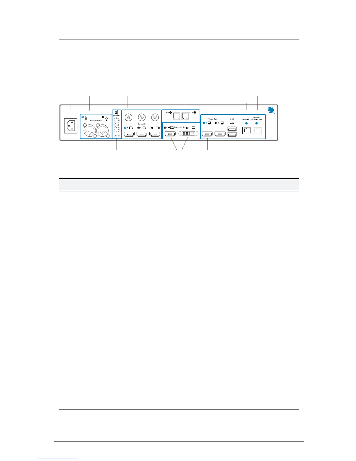
The connectors
The figure below shows the connectors on the rear of the GTm 5250 codec.
Microphone
Audio line-out
PTZ
camera
control
Power
PC video-in
(optional)
Network
PTZ camera
Telepresence
screen 1
Telepresence screen 2
(optional)
StarLeaf
touchscreen controller
Audio line-in
COM
The table below describes the connectors:
Connector Description
Microphone In
XLR-F connectors. Connect one or two StarLeaf microphones
Audio line-in
3.5mm line level stereo audio connector. You can input audio from a
computer for example. This audio input will be heard at the far end of
any video call
Audio line-out
3.5mm stereo audio connector. Connect to the screen or to a local
loudspeaker system
COM
RS-232 connectors. There is an API option for the GTm and an API guide is
available. The serial API uses
COM2
. There is also an IP-based API
Camera
control
Mini-DIN-8 connector for controlling zoom, pan, and tilt using VISCA™
protocol. Connect the camera control cable from the PTZ video
conferencing camera
Camera input
HDMI connector. Connect the camera cable from the PTZ video
conferencing camera
Computer In
HDMI and DVI-I connectors. Connect a PC to share a desktop in a video
call. In the case where you have connected a PC to both connectors,
content can be shared from the last PC that was connected
Video Out
HDMI x2
HDMI connectors. These connectors output video (1080p60 only) to the
screens
USB
Reserved for future expansion
Network
10/100/1000 Mbit/s auto-sensing Ethernet port. Connect to the network
StarLeaf
Controller
Connect to the StarLeaf touchscreen controller
StarLeaf Installation Guide Page 4 of 17
Page 5

About the codec
Connector Description
Power
An IEC mains power connector . The codec automatically adjusts to the
supply voltage. Use the supplied power cable to connect the codec to
the power. Connect all other cables before connecting the power
LEDs
There are Power and Status LEDs on the front of the codec. LED behavior is described in
Appendix: LED behavior (p16).
Dimensions
The GTm 5250 is designed to fit into a 19" communications rack and occupies 1.5U of
height.
Width
Depth
Height
Dimension Metric American
Width 420 mm 16.55 in.
Depth 210 mm 8.5 in.
Height (with feet attached) 72mm 2.9 in.
Height (without feet attached) 65mm 2.6 in.
Using the correct HDMI and DVI cables
When connecting HDMI or DVI cables to the camera inputs, the PC input, and the
telepresence screen display outputs, ensure you use the correct gauge of HDMI/DVI
cable. For short cable lengths of up to 5m (17 feet), use 28AWG or thicker core. For longer
lengths, use 24AWG or thicker. StarLeaf does not support the use of HDMI or DVI cables of
longer than 15m (49 feet) with the codec.
StarLeaf Installation Guide Page 5 of 17
Page 6
About the touchscreen controller
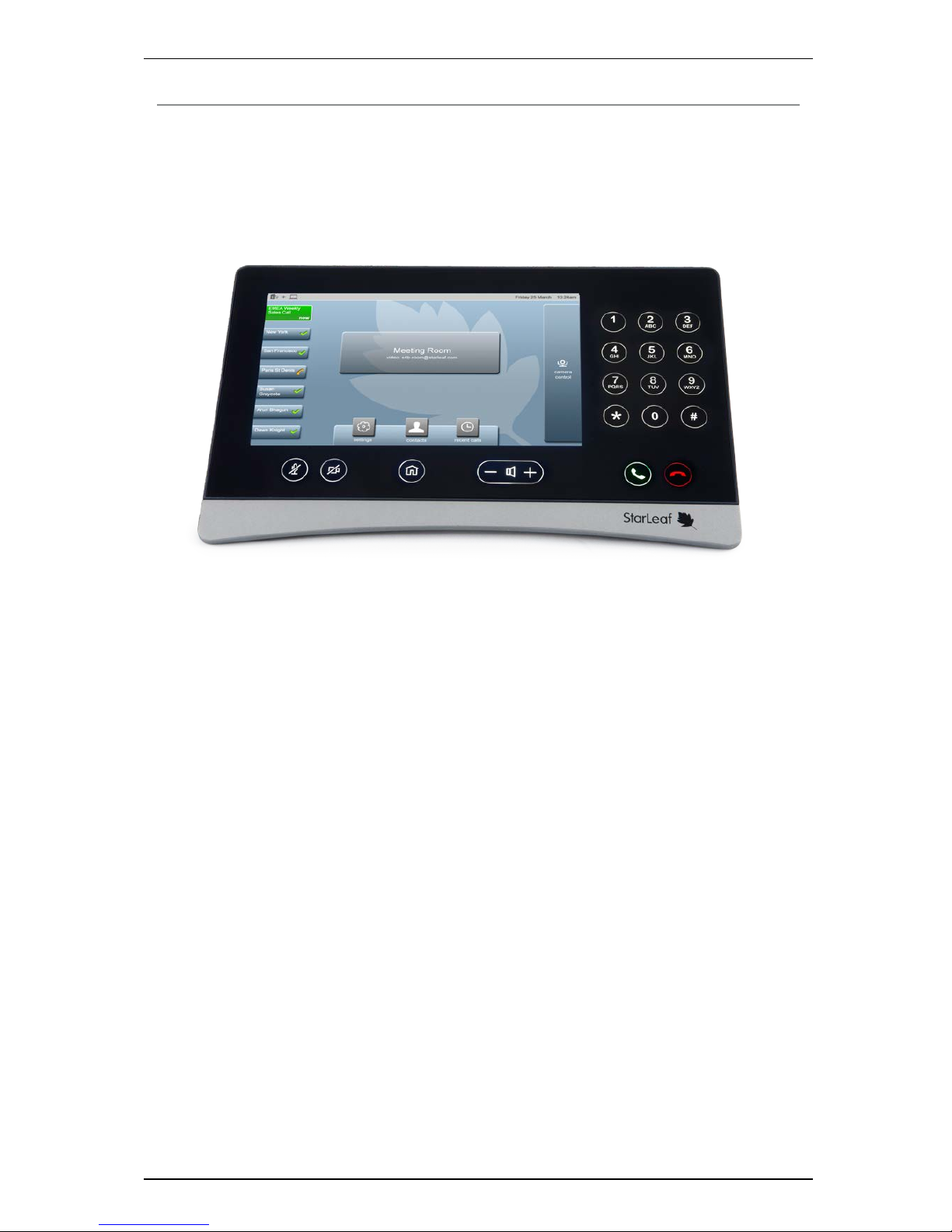
About the touchscreen controller
The GTm 5250 comes with a touchscreen controller: the StarLeaf Touch 2035. You will use
the touchscreen controller as the means for making, and controlling video calls with GTm
5250. Through the touchscreen controller, you will access the directory and contacts,
recent calls, and also the screen-share controls when in a video call.
The StarLeaf Touch 2035
StarLeaf Installation Guide Page 6 of 17
Page 7

Installing GTm 5250
Installing GTm 5250
Before installing the StarLeaf GTm 5250, read the safety information at GTm 5250 safety
and compliance.
Pre-requisites
Before installing the GTm 5250, ensure you have the following:
n One or two telepresence screens that support a 1080p60 input format
n Supported video camera
n Microphone
n StarLeaf touchscreen controller
Note: If you are not using a separate audio system, ensure that you use televisions that
have an audio-output capability. In this case, you will also need to use the supplied audio
injector. For more information, refer to Using the audio injector (p15).
Unpack the GTm 5250. The package contents is:
n Codec (with feet attached)
n Audio injector
n Installation sheet
n Rack mounting ears kit
n Cables
l Power cable
l DVI-I to DVI-I cable
l HDMI to HDMI cables (two) (connects codec to screens)
l 3.5mm jack to 3.5mm jack (connects codec to PC video and audio)
l Network cables
n Adaptors for the codec-to-PC cable
l DVI-I to HDMI
l DVI-I to VGA
l DVI-I to DVI-D
Positioning the codec
1. Ensure you have chosen an appropriate installation site:
l The codec must be accessible with all cables easily connected
l You must provide ventilation for the codec; leave a space of at least 10cm (4
inches) behind, in front, and to the left and right of the codec
l Use a grounded AC power outlet for the codec
2. Rack mount the unit or place on firm horizontal surface. The codec is 1.5 U high (with
removable feet detached) and fits in most standard 19-inch racks.
StarLeaf Installation Guide Page 7 of 17
Page 8

Installing GTm 5250
Connecting network cables to the codec
1.
Using an Ethernet cable, connect the StarLeaf Controller Only connector on the
codec to the PoE network port on the rear of the touchscreen controller. The network
port on the touchscreen controller is marked with this symbol:
2.
Using an Ethernet cable, connect the Network port on the rear of the codec to an
Ethernet switch in your network. The Ethernet port is a 10/100/1000 Mbit/s auto-sensing
port and is set to ‘auto’ by default.
Note: In all cases, the speed and duplex settings at either end of the connection must
be identical. Using non-matching settings causes severe packet loss.
To configure the network speed and duplex settings of the codec’s Network port: on
the touchscreen controller that you have connected to the codec, go to settings >
networking > network port speed.
Note: By default, the GTm 5250 will use DHCP to acquire an IP address. If necessary, you
can configure the GTm 5250 with a static IP address, to do so:
On the touchscreen controller that you have connected to the codec, go to settings >
networking, switch off DHCP and edit the IP address, netmask, gateway, and nameserver
fields.
Connecting the camera and microphone
1.
Connect the PTZ camera: connect the camera to Camera Inwith the camera control
cable and the camera video input cable and then connect power to the camera.
2.
Connect the microphone to Microphone In. Note that if required, you can connect
third-party microphones to either the XLR connectors or the Line-In connector. In this
case, you will need to configure the audio inputs from the web user interface (see
Audio configuration (p11))
Connecting screens and loudspeakers
On the GTm 5250, the audio emits from the audio-out connector on the rear of the
codec. Either:
n
Connect the Line out connector on the rear of the codec to amplifier and
loudspeakers. Connect one telepresence screen to Video Out HDMI 1. If you have a
second telepresence screen, connect it to Video Out HDMI 2.
or
n To send the audio over HDMI to the loudspeakers of the screen, use the supplied audio
injector as shown in Using the audio injector (p15) to connect screen 1 to the codec. If
you have a second telepresence screen, connect it to Video Out HDMI 2.
Connecting power
n Using the supplied power cable, connect the IEC mains power connector on the rear of
the codec to the mains power.
StarLeaf Installation Guide Page 8 of 17
Page 9

Installing GTm 5250
Creating a user account
On your Lync/Skype for Business server, create a new user account for the GTm 5250.
Make a note of the authentication details. (You can use an existing account if you prefer.)
Configuring the GTm 5250
Initial configuration
1. On the GTm 5250 touchscreen controller, press the settings button to view settings and
the IP address.
2. In a web browser, navigate to the IP address of the GTm 5250.
3.
Go to Skype for Business and type the authentication details of the new user account
and select Save. MS Office 365 users must enter sign-in address and password. Onpremise Lync/Skype for Business users must enter sign-in address, username and
password.
The GTm will sign in to the Skype for Business/Lync server:
StarLeaf Installation Guide Page 9 of 17
Page 10

Installing GTm 5250
4.
Go to Upgrade, check that the GTm 5250 is running the most recent GTm 5250 software
version. Here you can allow the GTm 5250 to download the latest version from the
StarLeaf server if it can (if it has access to the public Internet). Alternatively, you can
download the firmware from http://support.starleaf.com/product/room/gtm-5250 and
provide a URL to install that new version.
5. If your deployment has an on-premise MS Lync or Skype for Business server, upload the
required certificate authority to connect to your deployment. To do this, go to
Certificate Authorities. (The certificate format must be one of: .crt .cer .zip.)
StarLeaf Installation Guide Page 10 of 17
Page 11

Installing GTm 5250
Audio configuration
Go to Audio. You will have connected one of the following:
n
StarLeaf microphones: If you have connected a StarLeaf microphone, ensure StarLeaf
XLR microphones is selected. Note that any audio played to Line in connector (PC
audio for example) will also be mixed with the microphone and sent to anyone you call.
You are able to alter the Line in gain:
n
Third-party XLR microphones: If you have connected a third-party XLR microphone,
select Third-party microphones . You can control phantom power, echo cancellation
and gain for the microphone. Refer to the documentation that accompanied the
third-party microphone for information about what is required. Note that any audio
played to Line in connector (PC audio for example) will also be mixed with the
microphone and sent to anyone you call. You are able to alter the Line in gain:
n
Microphones connected to Line-In: If you have connected a micropohe or a
microphone mixer to the Line In connector, select Line In. You can control echo
cancellation and gain for the microphone. Refer to the documentation that
accompanied the third-party microphone for information about what is required:
StarLeaf Installation Guide Page 11 of 17
Page 12

Installing GTm 5250
Network configuration
n
Proxy server: If there is a proxy server for your deployment, you will need to configure the
details of that for the GTm 5250. Note that this is the same configuration as you would
use for a PC running a Skype for Business/Lync client in the same location on your
network. To configure the proxy server settings, go to Proxy Server:
n
QoS: The GTm 5250 supports the use of QoS. If you have QoS configured on your
network, you can configure the GTm 5250 with the relevant settings. To do so, go to
QoS:
StarLeaf Installation Guide Page 12 of 17
Page 13

Installing GTm 5250
Allowing users to connect a laptop or other digital
sources to the GTm 5250
Connect the DVI-I to DVI-I cable to Computer In 2 on the rear of the codec. For the
convenience of the GTm 5250 users, leave the other end of the cable on the meeting
room table. This allows users to connect a laptop to the GTm 5250 when they need to do
so. The GTm 5250 includes a selection of adaptors to be used with the DVI-I to DVI-I cable
where the video output of a PCis other than DVI-I (for example, VGA, HDMI, DVI-D).
Additionally, you can connect an HDMI source to Computer In 1 on the rear of the codec.
This can be useful where you have a permanent digital source that you want to connect
to the GTm, for example an Apple TVor whiteboard.
When users are in a meeting, they can select to share content using the touchscreen
controller. If more than one source is connected, the GTm 5250 will display content from
the most-recently connected source.
Connect PC audio out (or indeed another audio source) to the audio line-in on the rear of
the codec to send PC audio to the speakers at the far end of the call.
Near-end camera control for GTm 5250
The Camera Control tab on the home screen provides you with controls for the GTm 5250
PTZ camera.
The active camera selector will reflect the currently selected camera.
The near-end camera control allows you to pan, tilt, and zoom your camera. This control is
available both in a call and before you make a call.
StarLeaf Installation Guide Page 13 of 17
Page 14

Typical installation of GTm 5250
This diagram shows a typical installation of a GTm system.
Configuration
To view settings and IP address, double-press the home
button on the controller.
To register the GTm and to configure audio, display,
and other settings browse to the IP address of the GTm.
Microphone
Telepresence screen 2
(Optional)
Telepresence
screen 1
PC video-in
(Optional)
Power
Network
StarLeaf Touch 2035
Amplifier and loudspeakers
(Optional)
The selector on the rear of the PTZ camera
must be correctly set. Refer to the camera
documentation, or to the GTm documentation
on www.starleaf.com
Power supply
for camera
PTZ camera
control (VISCA In)
PTZ camera
video-out
StarLeaf GroupTelepresence InstallationGuide Page 14 of 17
Page 15

Using the audio injector
Using the audio injector
If you want to send sound over HDMI to the screen of the GTm 5250 room system, you must
use the audio injector.
The dip switches on the audio injector must be correctly set. All dip switches must be zero
except Mode switch 0, which must be set to 1. This is shown below.
ModeEDID
3 2 110
0
1
100
StarLeaf Installation Guide Page 15 of 17
Page 16

Appendix: LEDbehavior
Appendix: LED behavior
Network port LED
LED State
Link/Activity LED (Yellow) (On the
left when looking at the port)
Solid yellow indicates there is a link, flashing when
there is activity, off when there is no link
Gigabit LED (Green)
(On the right when looking at the
port)
On for 1000 Mbit/s link, off for 10/100 Mbit/s link or
no link
StarLeaf Controller Port LED behavior
LED State
Link/Activity LED (Yellow) (On the
left when looking at the port)
Solid yellow indicates there is a link, flashing when
there is activity, off when there is no link
Gigabit LED (Green)
(On the right when looking at the
port)
On for 1000 Mbit/s link, off for 10/100 Mbit/s link or
no link
Power and Status LED behavior
Power LED Status LED State
Solid blue Solid yellow Power has been applied to the unit, but it has not
started services yet
Solid blue Solid green The unit has booted up and everything is working
properly
Solid blue Solid red There is a problem. This can indicate overheating
and/or fan failure
StarLeaf Installation Guide Page 16 of 17
Page 17

Legal information
Legal information
Third party software acknowledgments
Acknowledgments of third-party software are available at:
www.starleaf.com/support/legal
Disclaimers and notices
Copyright © StarLeaf 2016. All rights reserved.
This guide may not be copied, photocopied, translated, reproduced, or converted into
any electronic or machine-readable form in whole or in part without prior written
approval of StarLeaf Limited.
StarLeaf Limited reserves the right to revise this documentation and to make changes in
content from time to time without obligation on the part of StarLeaf Limited to provide
notification of such revision or change.
StarLeaf Limited provides this documentation without warranty, term, or condition of any
kind, either implied or expressed, including, but not limited to, the implied warranties,
terms or conditions of merchantability, satisfactory quality, and fitness for a particular
purpose. StarLeaf Limited may make improvements or changes to the product(s) and/or
the program(s) described in this documentation at any time. All other product and
company names herein may be trademarks of their respective owners.
StarLeaf Installation Guide Page 17 of 17
 Loading...