

StarLeaf Touch 2035, GT Mini 3330, Conference Phone 2220, GT Mini, Phone 2120 Installation Manual

StarLeaf GT Mini
Installation Guide
01 February 2018

Contents
About the codec 4
The connectors 4
Using the correct HDMI and DVI cables 5
Audio voltage levels 5
Extending the camera cables 6
CEC support 6
GT Mini dimensions and mounting 7
About the touchscreen controller 8
How to install GT Mini 3330 9
About the camera 15
Camera control for the PTZ camera 15
Camera presets 15
Audio settings for Group Telepresence 18
Microphone settings 18
StarLeaf microphones 18
3rd party XLR microphones 18
Line in microphones 19
Line out 19
Advanced settings 20
Auto-answer mode 20
API mode 20
Max send and receive rates 20
Typical installation of GT Mini 21
Using the Conference Phone 2220 22
LED behavior 22
Installing the Conference Phone 2220 22
Installing the Conference Phone 2220 23
Using Group Telepresence 24
About StarLeaf touchscreen controllers 25
Touchscreen controller features 27
Appendix: LED behavior 30
Network port LED behavior 30
StarLeaf Controller Port LED behavior 30
Legal information 31
StarLeaf GT Mini, 01 February 2018 Page 2 of 31

Third party software acknowledgments 31
Disclaimers and notices 31
StarLeaf GT Mini, 01 February 2018 Page 3 of 31
About the codec
About the codec
The connectors
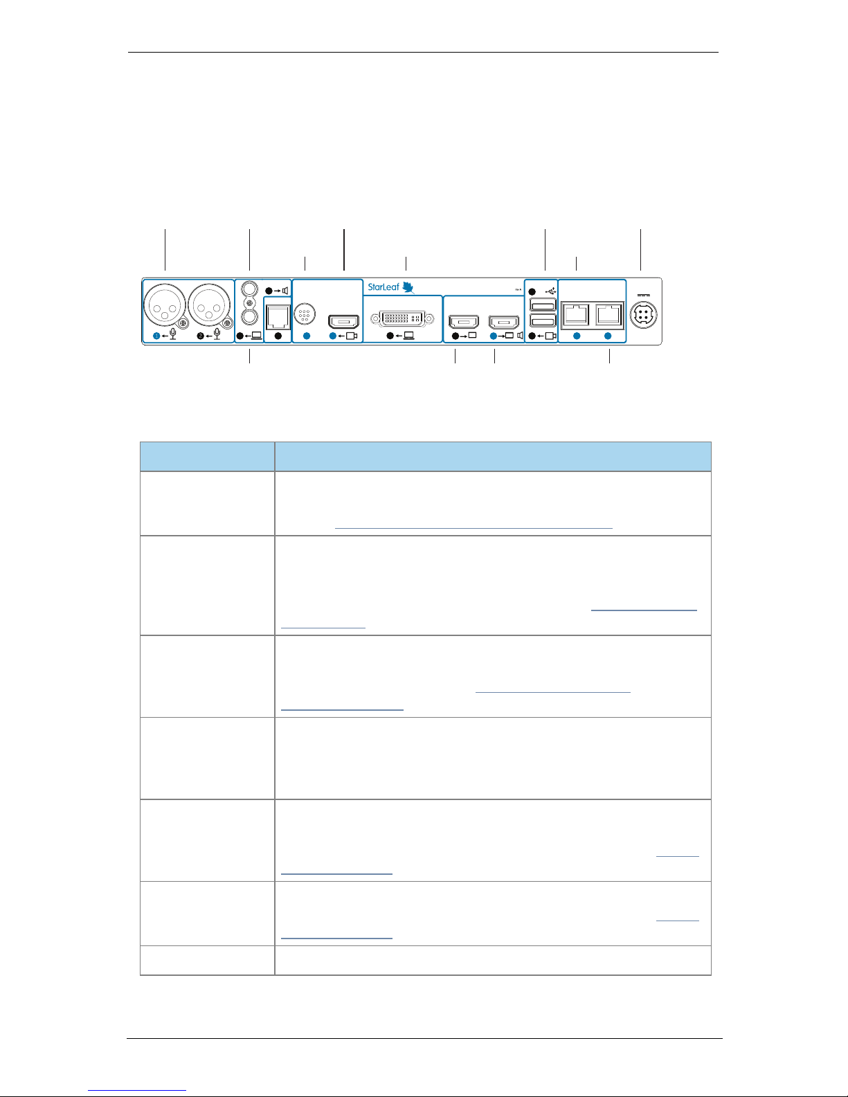
The figure below shows the connectors on the rear of the Group Telepresence 3330 (GT
Mini) codec.
Camera
Control
COM
360-00230
Network
Video Out
Camera In
Link/Act
Gigabit Link/Act Gigabit
Mic In
Computer In DVI-I
DC 48V
USB
Line Out
Line In
3330 Group Telepresence
Microphone Audio-out PTZ camera (optional)
PTZ camera
control
(optional)
USB camera (optional) Power
Telepresence
screen 1
Telepresence
screen 2
(optional)
PC video-in (optional) Network
StarLeaf Touch
Audio-in
+
B A
HDMI
StarLeaf
Controller Only
The table below describes the connectors:
Connector Description
Microphone
XLR-F connectors. Connect the microphone. You can alter the
power and gain settings of the microphone via the StarLeaf Portal
(refer to Audio settings for Group Telepresence (p18))
Audio line-in
3.5mm line level stereo audio connector. You can connect a line
level microphone source or input other audio, for example a
computer. In either case, ensure you have the correct settings for
audio in the Portal. For more information, refer to How to install GT
Mini 3330 (p9)
Audio line-out
3.5mm stereo audio connector. If required, you can connect to a
local loudspeaker system. You can alter the line-out audio settings
via the StarLeaf Portal (refer to Audio settings for Group
Telepresence (p18))
COM
This port is for a 4P4C connector providing an RS-232 interface. This is
the same connector used in RJ9, RJ10, and RJ22. There is both a
serial and an IP API option for the GT Mini and a StarLeaf Room
Systems API guide is available
Camera control
Mini-DIN-8 connector for controlling zoom, pan, and tilt using
VISCA™ protocol. You connect to this port if you are using a PTZ
video conferencing camera. For more information, refer to About
the camera (p15)
Camera input
HDMI connector. You connect to this port if you are using a PTZ
video conferencing camera. For more information, refer to About
the camera (p15)
Computer In
DVI-I connector. Connect a PC to share a desktop in a video call
StarLeaf GT Mini, 01 February 2018 Page 4 of 31
About the codec
Connector Description
Video Out HDMI x2
HDMI connectors. Video Out connector A outputs both audio and
video (1080p60 only) to the screen. If you are connecting a second
screen, connect it to HDMI port B
USB x2
USB connectors. If you are using a USB webcam, you connect it to
one of the USB ports
Network
10/100/1000 Mbit/s auto-sensing Ethernet port. Connect to the
network
StarLeaf Controller
Only
Connect to the PoE port on the rear of the StarLeaf touchscreen
controller to both power the touchscreen controller and to allow
communication between the touchscreen controller and the
codec
+48V power
Connect to the supplied AC/DC adaptor
There are LEDs on the Network port and the StarLeaf Controller Only port of the codec
indicating the status of the network link, and the link to the StarLeaf touchscreen
controller. LED behavior is described in Appendix: LED behavior (p30).
Note: Older models of GT Mini have HDMI ports labeled 1 and 2. In this case, plug screen 1
into port 2.
Using the correct HDMI and DVI cables
When connecting HDMI or DVI cables to the camera inputs, the PC input, and the
telepresence screen display outputs, ensure you use the correct gauge of HDMI/DVI
cable. For short cable lengths of up to 5m (17 feet), use 28AWG or thicker core. For longer
lengths, use 24AWG or thicker. StarLeaf does not support the use of HDMI or DVI cables of
longer than 15m (49 feet) with the codec.
Audio voltage levels
If you are using external equipment to connect the GT Mini to your microphones, you
need to be aware of the required audio voltage levels for XLR, audio line-in, and audio
line-out:
n XLR Mic in sensitivity -40dBu to -13dBu (The StarLeaf Portal 0dB gain setting is equivalent
to -13dBu)
n 3.5mm Line in sensitivity -16dBu to +12dBu (The StarLeaf Portal 0dB setting is equivalent to
+7dBu)
n 3.5mm Line out range -40dBu to +2 dBu (The StarLeaf Portal 0dB gain setting is
equivalent to +2dBu)
Phantom power is compatible with active microphones that are designed for 48V
phantom power. The following are specifications of the power supply:
n Output voltage when operational, no load is 45.3V +/- 4%
n Output voltage when muted, no load is 35.3V +/- 4%
n Power output source impedance is 1.975kOhms +/- 2%
StarLeaf GT Mini, 01 February 2018 Page 5 of 31

About the codec
Extending the camera cables
StarLeaf room systems that use a PTZ camera are provided with camera connection
cables of 5m in length. If you need to install the camera further than 5m from the room
system, you must extend those cables.
You can extend those cables using a third-party product called an extender. This product
effectively carries the media and camera-control signals across a cat 6 Ethernet cable.
StarLeaf has partnered with Sound Control Technologies to provide this solution which is
available at http://www.soundcontrol.net/solutions/#
CEC support
CEC is supported by GT Mini 3330 as a beta feature. If you want to enable CEC support on
your GT Mini 3330, contact Starleaf Support.
CEC allows the GT Mini to communicate control commands to the connected screen/s
across HDMI. When enabled, it will put the screen/s to sleep in between calls. GT Mini will
wake the screens when it receives, or you make, a call. If the screens are displaying from a
different source when GT Mini receives, or you make, a call, GT Mini will tell the screens to
switch the source to GT Mini.
StarLeaf GT Mini, 01 February 2018 Page 6 of 31
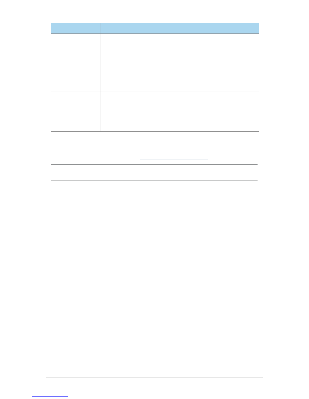
GT Mini dimensions and mounting
GT Mini dimensions and mounting
StarLeaf GT Mini, 01 February 2018 Page 7 of 31
About the touchscreen controller
About the touchscreen controller
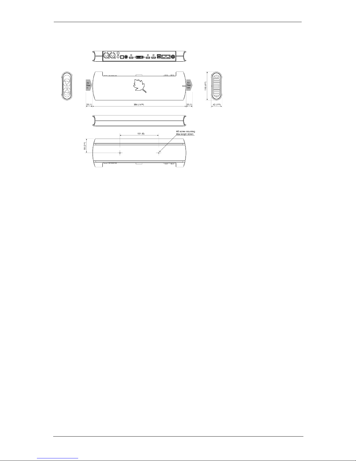
Every Group Telepresence system comes with a touchscreen controller: the StarLeaf
Touch 2035. You use the touchscreen controller as the means for making and controlling
video calls with Group Telepresence. Through the touchscreen controller, you can access
the directory and contacts. You can use the touchscreen controller to create ad hoc
conferences, and to add and remove participants.
The StarLeaf Touch 2035
StarLeaf GT Mini, 01 February 2018 Page 8 of 31

How to install GT Mini 3330
How to install GT Mini 3330
Before installing a StarLeaf product, read the safety information at
www.starleaf.com/safety.
Pre-requisites
Before installing the room system, ensure you have the following:
n A StarLeaf Cloud account
n One or two telepresence screens that support a 1080p60 input format (use televisions
that have an audio-output capability, or alternatively, you can connect loud speakers
to the codec). If the televisions have an option to enable "Game Mode" or "PC Mode",
then do so as this reduces media processing delays and improves video experience
n Supported video camera
n Network connection routable to the public Internet
n Microphone
n StarLeaf touchscreen controller (not installed)
Unpack the room system. The package contents is:
n Codec
n Installation sheet
n AC/DC adaptor
n Cables
l Power cable
l HDMI to HDMI cables (two) (connects codec to screens)
l DVI-I to DVI-I cable (connects codec to PC video)
l Network cable
n Adaptors for the codec-to-PC cable
l DVI-I to HDMI
l DVI-I to VGA
l DVI-I to DVI-D
Positioning the codec
1. Ensure you have chosen an appropriate installation site:
l The codec must be accessible with all cables easily connected
l You must provide ventilation for the codec; leave a space of at least 10cm (4
inches) behind, in front, and to the left and right of the codec
l Ensure that the power switch is easily accessible; the power switch is the main
disconnect device for the codec
l Use a grounded AC power outlet for the codec
2. Place the unit on a firm horizontal surface. If you intend to mount the unit, refer to GT
Mini dimensions and mounting (p7).
Connecting cables to the codec
1. Using an Ethernet cable, connect the StarLeaf Controller port on the codec to the
network port (PoE) on the rear of the touchscreen controller. The network port on the
touchscreen controller is marked with this symbol:
StarLeaf GT Mini, 01 February 2018 Page 9 of 31

How to install GT Mini 3330
Note: The touchscreen controller must connect directly to the codec; do not
connect the touchscreen controller via a switch to the codec.
Note: If you are using the StarLeaf Conference Phone 2220, refer to Installing the
Conference Phone 2220 (p23).
2. Using an Ethernet cable, connect the Network port on the rear of the codec to an
Ethernet switch in your network. The Ethernet port is a 10/100/1000 Mbit/s auto-sensing
port and is set to ‘auto’ by default.
Note: In all cases, the speed and duplex settings at either end of the connection must
be identical. Using non-matching settings causes severe packet loss.
To configure the network speed and duplex settings of the codec’s Network port: on
the touchscreen controller that you have connected to the codec, go to settings >
networking > network port speed.
3.
Connect one telepresence screen to Video Out A. If you have a second telepresence
screen, connect it to Video Out B. (Note: on older systems, if you have only one screen,
connect it to the port labeled: HDMI 2.)
4. Connect the camera. One of:
l
PTZ camera: connect the camera to Camera Control and to Camera In and then
connect power to the camera
l
Webcam: connect the camera to the lower of the two USB ports
5.
Connect the microphone to Microphone 1. (Note that you can, instead, use a
microphone connected to Audio In. If you do so, refer to Using the line-in connector
and to Audio settings for Group Telepresence (p18)).
6. Using the supplied AC/DC adaptor and power cable, connect power to the codec.
The power LED on the side of the codec lights.
StarLeaf GT Mini, 01 February 2018 Page 10 of 31
 Loading...