

Sta-Rite Industries Manifold Bypass Valve User Manual
PRESS
TAB
VENT
PILOT
OFF
ONON
Internal Bypass Valve Kit
2661 1096
Risk of fire, explosion, and electrical shock.
Heater service and repair must be performed by a qualified
installer, service agency, or the gas supplier.
Location
The Manifold Bypass Valve is located inside the
Inlet/Outlet Manifold.
NOTICE: The Inlet/Outlet Manifold must be removed to
service or replace the Manifold Bypass Valve.
Function
The Manifold Bypass Valve maintains a constant flow to
the Heat Exchanger by opening to allow excess flow to
bypass the Heat Exchanger.
Servicing Procedure
1. Turn off the filter pump and all electrical power to the
heater. Close the external Manual Gas Valve.
2. If the heater is below the water level of the pool, close
isolation valves to avoid draining the pool.
3. Disconnect the gas pipe back to the external Manual
Gas Valve to allow the heater to move enough to provide working clearance.
4. Remove Drain Plug under the Inlet/Outlet Manifold to
drain the heater.
5. Loosen the inlet/outlet piping unions.
6. Unscrew the Thermal Regulator Plug.
The Thermal Regulator Spring is behind the
plug and will cause the plug to fly if not restrained.
7. Remove the Thermal Regulator along with the spring
attached to it.
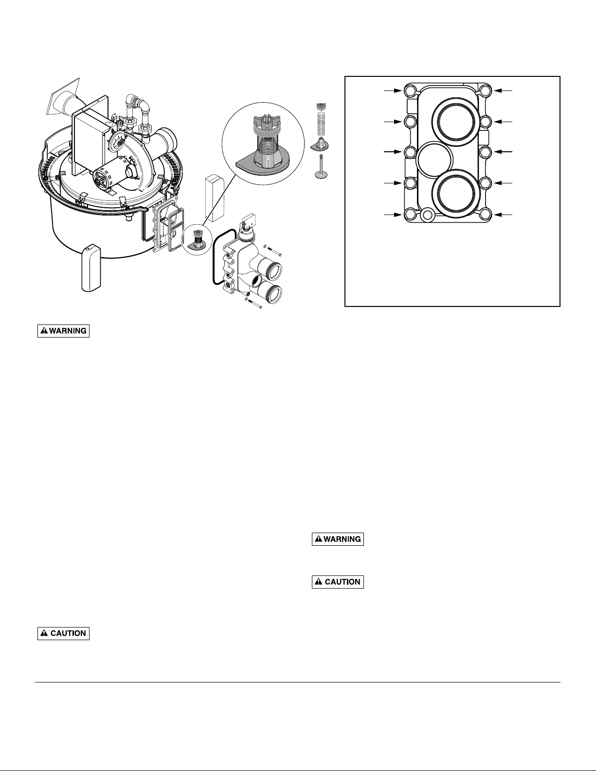
8. Remove the Inlet/Outlet Manifold by removing the 10
bolts holding the Manifold to the tube sheet.
9. Carefully pry the bottom plate off of the Manifold. The
Manifold O-ring and insert will come off with the bottom plate.
10.Remove the baffle plate to gain access to the Internal
Bypass Valve chamber.
11. Remove the Bypass Valve Assembly and replace it with
a new one.
12. To Replace the valve, reverse Steps 1 through 10 above.
NOTE: Carefully tap parts together to allow Manifold bolts to
start. When tightening the Inlet/Outlet Manifold bolts, tighten
to 75-115 in-lb. Make sure that O-Rings and sealing surfaces
are clean and that the O-Rings are correctly positioned.
O-ring replacement is recommended.
Safety Precautions:
Fire or explosion hazard. Disconnect all
power to the heater and close the External Manual Gas
Valve before starting this procedure.
Projectile hazard. The Thermal Regulator
plug has a spring behind it. Restrain it when removing it
from the Manifold to prevent it from flying and possibly
injuring persons nearby.
Manifold Bypass Valve
Procedure for Plastic Manifold. See other side of sheet for Cast Iron Manifold with Adapter Procedure.
Sta-Rite Pool/Spa Group
293 Wright Street, Delavan, WI 53115
North America: 800-752-0183, FAX 800-582-2217
International: 262-728-5551, FAX: 262-728-4461, TELEX: ITT 4970245
www.sta-ritepool.com
Union City, TN • Delavan, WI • Mississauga, Ont. • Murrieta, CA
Printed in U.S.A. © 2001, Sta-Rite Industries, Inc. S448 (Rev. 2/27/01)
Manifold Bypass Valve Kit
Torque the Manifold bolts in sequence
as shown, then go once around the
Manifold and re-tighten the bolts to
specified torque.
98
54
12
3 6
710
75-115 in.-lbs./8.4-12.9 nm
3883 0101

PRESS
TAB
VENT
PILOT
OFFOFF
ONON
Internal Bypass Valve Kit P/N 77707-0001
Risk of fire, explosion, and electrical shock.
Heater service and repair must be performed by a qualified
installer, service agency, or the gas supplier.
Location
The Manifold Bypass Valve is located inside the
Inlet/Outlet Manifold.
NOTICE: The Inlet/Outlet Manifold must be removed to
service or replace the Manifold Bypass Valve.
Function
The Manifold Bypass Valve maintains a constant flow to
the Heat Exchanger by opening to allow excess flow to
bypass the Heat Exchanger.
Servicing Procedure
1. Turn off the filter pump and all electrical power to the
heater. Close the external Manual Gas Valve.
2. If the heater is below the water level of the pool, close
isolation valves to avoid draining the pool.
3. Disconnect the gas pipe back to the external Manual
Gas Valve to allow the heater to move enough to provide working clearance.
4. Open the Drain Cock under the Inlet/Outlet Manifold
to drain the heater.
5. Loosen the inlet/outlet piping unions.
6. Unscrew the Thermal Regulator Plug.
The Thermal Regulator Spring is
behind the plug and will cause the plug to fly
if not restrained.
7. Remove the Thermal Regulator along with the spring
attached to it.
8. Remove the Inlet/Outlet Manifold by removing the 8
bolts holding the Manifold to the Manifold Adapter.
9. Remove the baffle plate and O-ring to gain access to
the Internal Bypass Valve chamber.
10.Remove the Bypass Valve Assembly and replace it with
a new one.
11. To Replace the valve, reverse Steps 1 through 10 above.
NOTE: When tightening the Inlet/Outlet Manifold bolts, tighten to 125-150 in-lb. Make sure that O-Ring and sealing surfaces are clean and that the O-Ring is correctly positioned.
Safety Precautions:
Fire or explosion hazard. Disconnect all
power to the heater and close the External Manual Gas
Valve before starting this procedure.
Projectile hazard. The Thermal Regulator
plug has a spring behind it. Restrain it when removing it
from the Manifold to prevent it from flying and possibly
injuring persons nearby.
REPAIR PARTS LIST
Manifold Bypass Valve
Procedure for Cast Iron Manifold with Adapter. See other side of sheet for Plastic Manifold Procedure.
Part Part
Description Qty. No.
Internal Bypass Valve Kit 77707-0001
Spring Retainer 1 42001-0088
Spring 1 37607-0012
Separator Plate 1 42001-0011
Bypass Valve Poppet 1 42001-0014
Manifold Bypass Valve Kit
 Loading...