

Page 1
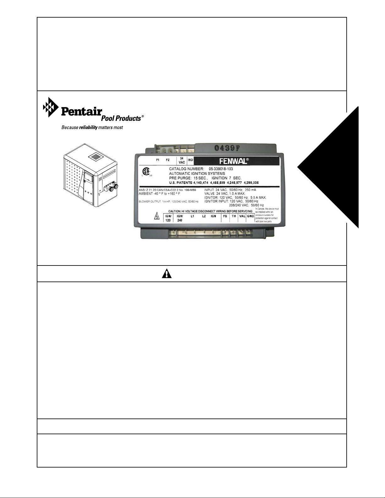
MiniMax® NT Series Heaters
IGNITION MODULE INSTALLATION INSTRUCTIONS
Consumer
Retain For
Reference
To
Future
OBSOLETE FENWAL IGNITION MODULE
WARNING
FOR YOUR SAFETY - READ BEFORE OPERATING
• If you do not follow these instructions exactly, a fire or explosion may result, causing
property damage, personal injury or loss of life.
• Improper installation, adjustment, alteration, service or maintenance can cause
property damage, personal injury or death. Installation and service must be performed
by a qualified installer, service agency or the gas supplier.
IMPORTANT SAFETY INSTRUCTIONS
READ AND FOLLOW ALL INSTRUCTIONS
SAVE THESE INSTRUCTIONS
For additional free copies of this manual; call (800) 831-7133.
Pentair Water Pool and Spa, Inc.
1620 Hawkins Ave., Sanford, NC 27330 • (919) 566-8000
10951 W. Los Angeles Ave., Moorpark, CA 93021
Rev. A 1-30-07 1 P/N P/N 472721
• (805) 553-5000
Page 2
The Ignition Module you are trying to replace has been made obsolete by the manufacturer. This kit is
required to rewire your heater so that it can make use of the new ignition module. This change will not alter
the performance of the heater.
The heater must be electrically grounded and bonded in accordance with local codes or, in the absence of
local codes, in the USA, with the National Electrical Code, ANSI/NFPA 7; in Canada, with Canadian Electric
Code, CSA C22.1. All wiring must be done by a certified electrician.
CAUTION — Label all wires prior to disconnection when servicing controls. Wiring errors can cause improper and dangerous
operation. Wiring errors can also destroy the control board. Verify proper operation after servicing.
In order to install this new ignition module, the wiring harness will need to be modified as stated in these installation
instructions.
In cases where the heater has already been altered to accept this new ignition module, disregard these instructions;
instead, simply change out old and new ignition modules and install the three connectors in the same locations from which
they were removed.
Tools required
- Flat Head Screwdriver or Nut Driver
- Wire cutter
- Wire stripper
- Wire crimper for insulated terminals
WARNING —Risk of electrical shock or electrocution.
This heater contains wiring that carries high voltage. Contact with these wires could result in death or serious
injury to pool or spa users, installers, or others due to electrical shock, and may also cause damage to property.
Always disconnect power circuit before connecting the heater.
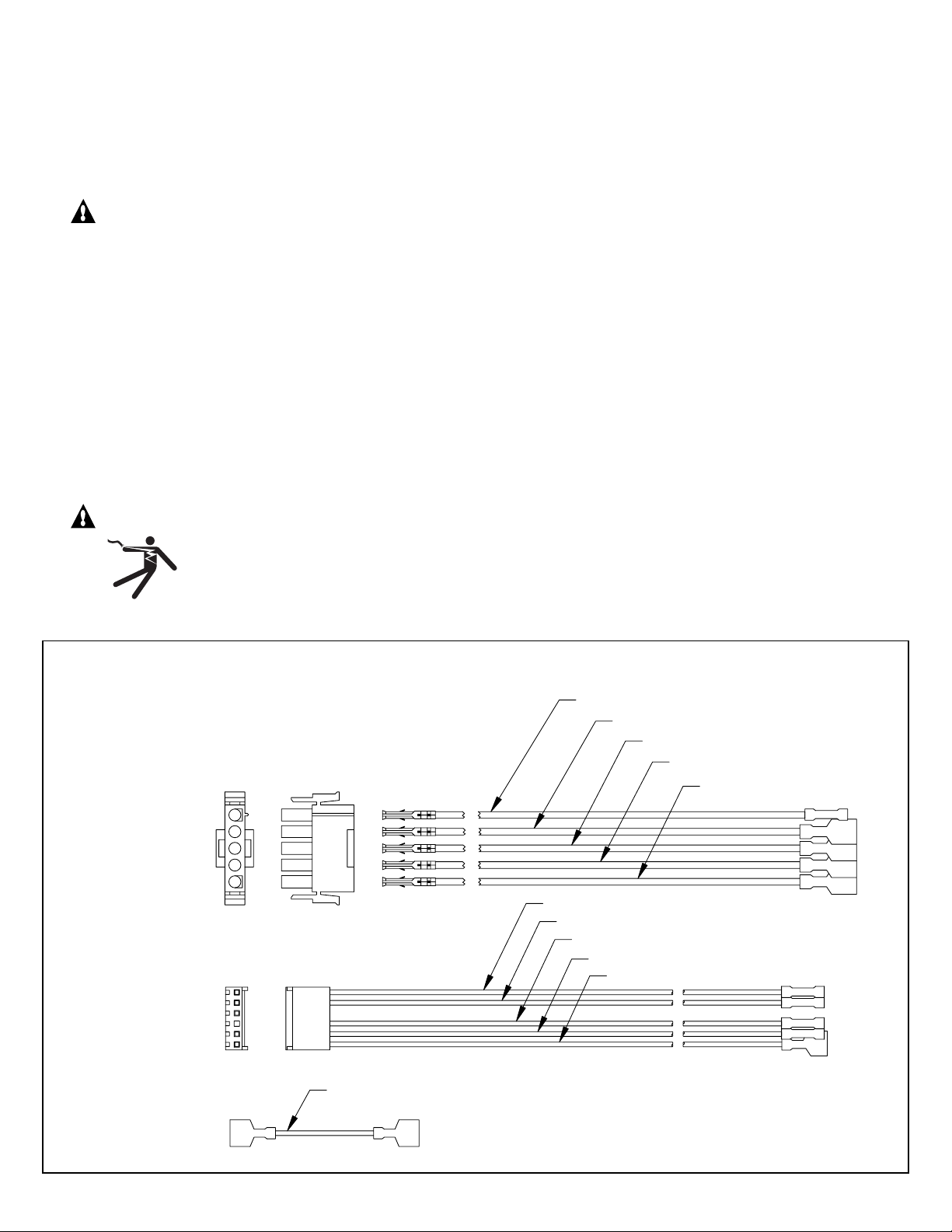
WIRING HARNESS COMPONENTS
1
PART NUMBER
472719
2
3
4
5
BROWN
WHITE
YELLOW
BLACK
BLUE
WHITE
RED
PURPLE
ORANGE
GREY
PART NUMBER
472720
WHITE
PART NUMBER
472724
P/N P/N 472721 2 Rev. A 1-30-07
Page 3

Installation instructions:
For MiniMax® NT Low NOx only:
NOTE: To avoid miss-wiring remove one wire at a time and in the sequence specified below:
1. Remove the connector from the IGN/120 terminal of the existing ignition module and attach it to the connector of the blue
wire of wire harness P/N 472719.
2. Remove the connector from the IGN/240 terminal of the existing ignition module and attach it to the connector of the yellow
wire of wire harness P/N 472719
3. Remove the connector from the L1 terminal of the existing ignition module and attach it to the connector of the black wire
of wire harness P/N 472719
4. Remove the connector from the L2 terminal of the existing ignition module and attach it to the connector of the white wire
of wire harness P/N 472719. You must remove the cap covering the male terminal in order to make the connection.
5. Remove the connector from the IGN terminal of the existing ignition module. Remove the female quick connector by cutting
the wire right next to it. Strip off the insulation leaving ¼-inch of exposed wire. Insert the stripped wire into the crimp
connector of the brown wire on wire harness P/N 472719 and crimp the wire in place. No bare wire is to be exposed once
complete.
6. Remove the connector from the TH terminal of the existing ignition module and attach it to the connector of the grey wire
of wire harness P/N 472720.
7. Remove the connector from the VAL terminal of the existing ignition module. Remove the female quick connector by cutting
the wire right next to it. Strip off the insulation leaving ¼-inch of exposed wire. Insert the stripped wire into the crimp
connector of the red wire on wire harness P/N 472720 and crimp the wire in place. No bare wire is to be exposed once
complete.
8. Remove the connector from the GND terminal of the existing ignition module. Remove the female quick connector by
cutting the wire right next to it. Strip off the insulation leaving ¼-inch of exposed wire. Insert the stripped wire into the crimp
connector of the white wire on wire harness P/N 472720 and crimp the wire in place. No bare wire is to be exposed once
complete.
9. Remove the connector from the 24VAC terminal of the existing ignition module. Remove the female quick connector by
cutting the wire right next to it. Strip off the insulation leaving ¼-inch of exposed wire. Insert the stripped wire into the crimp
connector of the purple wire on wire harness P/N 472720 and crimp the wire in place. No bare wire is to be exposed once
complete.
10. Remove the connector from the IND terminal of the existing ignition module. Remove the female quick connector by
cutting the wire right next to it. Strip off the insulation leaving ¼-inch of exposed wire. Insert the stripped wire into the
crimp connector of the orange wire on wire harness P/N 472720 and crimp the wire in place. No bare wire is to be
exposed once complete.
11. Jumper wire P/N 472724 is not used for the MiniMax NT Low NOx installation.
12. Remove connector attached to F1 and F2 from existing ignition module.
13. Remove existing ignition module from the heater by removing the two screws.
14. Install the new ignition module using the two screws provided.
15. Attach the three wire harness connectors to the new ignition module.
16. Use zip ties to secure any loosely hanging wires.
17. Place the new MiniMax NT Low NOx wiring diagram label over the old wiring diagram label. Be sure to clean and dry
surface of old label before applying the new one.
Rev. A 1-30-07 3 P/N P/N 472721
Page 4

For MiniMax® NT STD only:
NOTE: To avoid miss-wiring remove one wire at a time and in the sequence specified below:
1. Remove the connector from the IGN/120 terminal of the existing ignition module and attach it to the connector of the blue
wire of wire harness P/N 472719.
2. Remove the connector from the IGN/240 terminal of the existing ignition module and attach it to the connector of the yellow
wire of wire harness P/N 472719.
3. Remove the connector from the L1 terminal of the existing ignition module and attach it to the connector of the black wire
of wire harness P/N 472719.
4. Remove the connectors from the L2 and IGN terminals of the existing ignition module. Attach both wires to each other
using jumper wire P/N 472724.
5. Remove the connector from the FS terminal of the existing ignition module. Remove the female quick connector by cutting
the wire right next to it. Strip off the insulation leaving ¼-inch of exposed wire. Insert the stripped wire into the crimp
connector of the brown wire on wire harness P/N 472719 and crimp the wire in place. No bare wire is to be exposed once
complete.
6. Remove the connector from the TH terminal of the existing ignition module and attach it to the connector of the grey wire
of wire harness P/N 472720.
7. Remove the connector from the VAL terminal of the existing ignition module. Remove the female quick connector by cutting
the wire right next to it. Strip off the insulation leaving ¼-inch of exposed wire. Insert the stripped wire into the crimp
connector of the red wire on wire harness P/N 472720 and crimp the wire in place. No bare wire is to be exposed once
complete.
8. Remove the connector from the GND terminal of the existing ignition module. Remove the female quick connector by
cutting the wire right next to it. Strip off the insulation leaving ¼-inch of exposed wire. Insert the stripped wire into the crimp
connector of the white wire on wire harness P/N 472720 and crimp the wire in place. No bare wire is to be exposed once
complete.
9. Remove the connector from the 24VAC terminal of the existing ignition module. Remove the female quick connector by
cutting the wire right next to it. Strip off the insulation leaving ¼-inch of exposed wire. Insert the stripped wire into the crimp
connector of the purple wire on wire harness P/N 472720 and crimp the wire in place. No bare wire is to be exposed once
complete.
10. Remove the connector from the IND terminal of the existing ignition module. Remove the female quick connector by
cutting the wire right next to it. Strip off the insulation leaving ¼-inch of exposed wire. Insert the stripped wire into the
crimp connector of the orange wire on wire harness P/N 472720 and crimp the wire in place. No bare wire is to be
exposed once complete.
11. Remove connector attached to F1 and F2 from existing ignition module.
12. Remove existing ignition module from the heater by removing the two screws.
13. Install the new ignition module using the two screws provided.
14. Attach the three wire harness connectors to the new ignition module.
15. Use zip ties to secure any loosely hanging wires.
16. Place the new MiniMax NT STD wiring diagram label over the old wiring diagram label. Be sure to clean and dry surface
of old label before applying the new one.
SAVE THESE INSTRUCTIONS
© 2007 Pentair Water Pool and Spa, Inc. All rights reserved.
1620 Hawkins Ave., Sanford, NC 27330 • (919) 556-8000
10951 West Los Angeles Ave., Moorpark, CA 93021 • (805) 553-5000
This document is subject to change without notice.
Trademarks and Disclaimers: The Pentair Pool Products logo and MiniMax are registered trademarks of Pentair Water Pool and Spa, Inc.
Other trademarks and trade names may be used in this document to refer to either the entities claiming the marks and names or their products.
Pentair Water Pool and Spa, Inc. disclaims any proprietary interest in trademarks and trade names other than its own.
P/N P/N 472721 4 Rev. A 1-30-07
 Loading...