

Page 1
MagicFalls
Water Effects
®
User’s Guide
IMPORTANT SAFETY INSTRUCTIONS
READ AND FOLLOW ALL INSTRUCTIONS
SAVE THESE INSTRUCTIONS
Installation
and
Page 2

Technical Support
Sanford, North Carolina (8 A.M. to 5 P.M.)
Moorpark, California (8 A.M. to 5 P.M.)
Phone: (800) 831-7133
Fax: (800) 284-4151
Web sites: visit www.pentairpool.com and staritepool.com
© 2009 Pentair Water Pool and Spa, Inc. All rights reserved
This document is subject to change without notice
1620 Hawkins A ve., Sanford, NC 27330 • (919) 566-8000
10951 West Los Angeles Ave., Moorp ark, CA 93021 • (805) 553-5000
Trademarks and Disclaimers:
MagicFalls®, IntelliPro®, IntelliFlo® and Pentair Water Pool and S pa® are trademarks and/or registered trademarks
of Pentair Water Pool and S pa, Inc. and/or it s affiliated comp anies in the United S tates and/or other counrties.
Unless noted, names and brands of others that may be used in this document are not used to indicate an affiliation
or endorsement between the proprietors of these names and brands and Pentair Water Pool and S pa, Inc. Those
names and brands may be the trademarks or registered trademarks of those parties or others.
.
P/N 590051 Rev B 3-11-09
Page 3
Overview
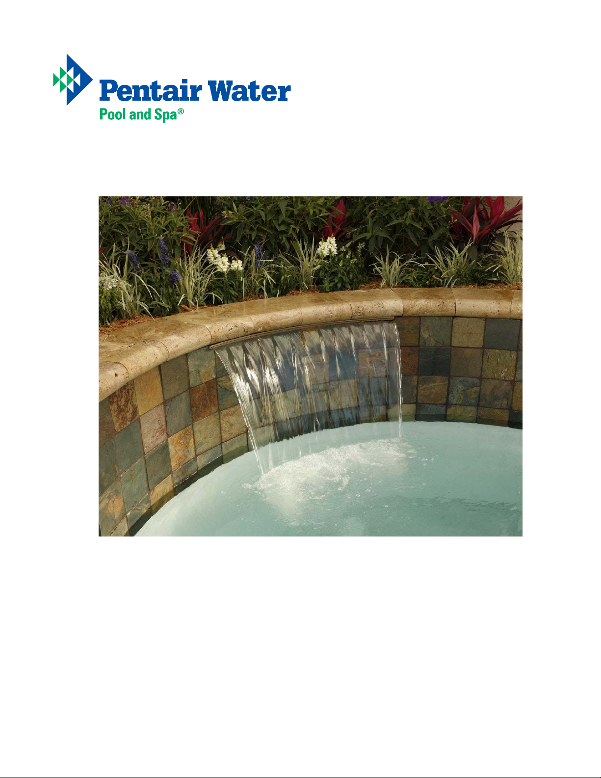
Perhaps no other feature contributes more to the beauty and tranquility of your poolscape than the sight and
sound of falling water. Built to the highest standard of quality , and “wet tested” to ensure that your water
effect will be soothing and beautiful , MagicFalls® water effects will transform your pool into a romantic
tranquil oasis, and a breathtaking focal point. This guide will take you through the steps of a successful
MagicFalls installation. Please read and follow the installation instruction carefully . Failure to follow the
recommended installation guidelines could void the warranty , and may result in injury.
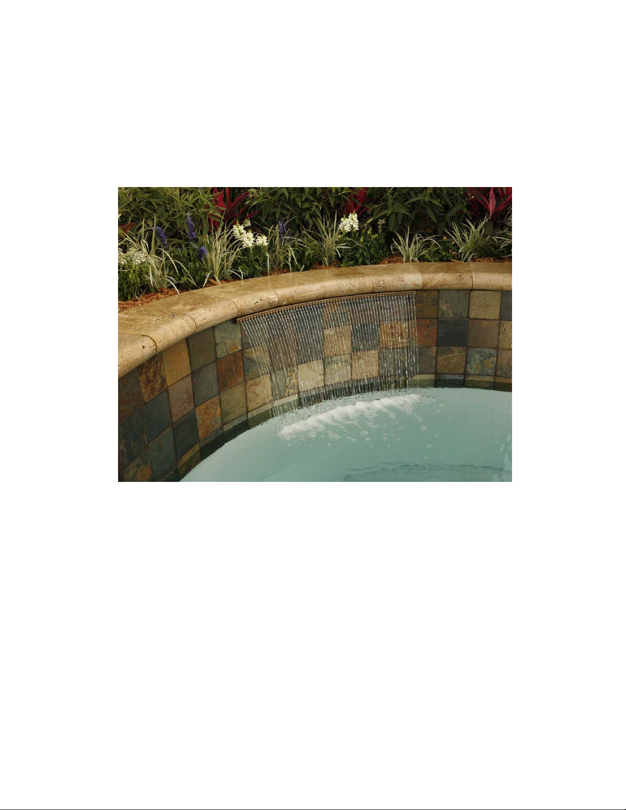
MagicFalls® Curved Rain Water Effect
1
Page 4
Design Guidelines for Waterfalls
There are six primary considerations in selecting a waterfall for a project:
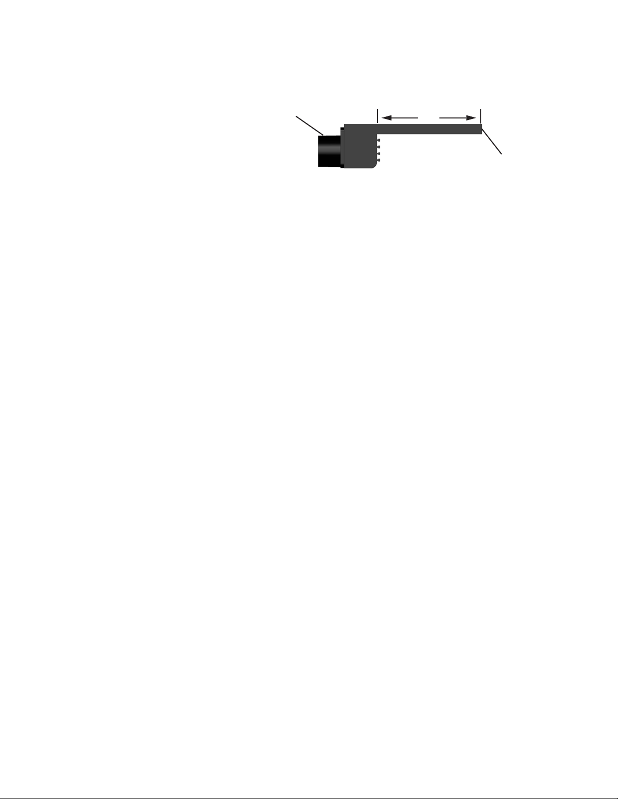
1. W ater effect
Rear feed
Lip
2. Waterfall length
3. Lip length (this depends on how and
where you mount the waterfall)
4. Color
Manifold Body
Effect
Discharge
5. W ater supply location: Rear (standard) or Bottom (optional)
6. Curved water effects can be field cut or factory cut for a nominal charge. Convex or concave curves
can be cut. You must leave 1” of lip in front of the manifold body , or the water effect will not work.
Important facts
z Sheet effects are thin, sensitive to wind, and the width of the sheet narrows the farther it falls. At
fall heights above 3’, the sheet effect begins to break apart and to produce an annoying buffeting noise. It is
recommended that a maximum mounting height of 3' should be used for sheet effects.
z Rain effects are less damaged by wind than are sheet effects. The effect does not narrow as the fall height
increases. It is recommended that a maximum mounting height of 6' should be used for rain effects.
z W aterfalls are typically installed in the bond beam, just above the tile line, or in a raised wall above the
bond beam. Three important considerations include: wall thickness, tile or stone thickness, and the weight
of the covering concrete or stone.
z Use a 20 micron cartridge filter to supply clean, filtered water to the waterfall. Do not use a DE or
Sand filter.
z Y ou should plan to supply approximately 15GPM per foot. The waterfall can operate on lower flow rates
(10GPM/ft minimum), but may not achieve the desired effect. Each waterfall should be equipped with a
flow control valve, located downstream from the filter, to adjust the flow to each waterfall. It is recommended
that you use an energy saving IntelliFlo
®
,
IntelliPro
®
pump to allow you to easily vary the flow to
the waterfall.
z The maximum head loss for any waterfall is 6 feet. Calculate and add the loss of your piping to determine
your pump requirement.
z Use 1-1/2" supply piping for each waterfall 4' and under. Use 2" supply piping for all waterfalls 5' and
over . Make sure you calculate the total head loss. Make sure you keep all debris out of the piping
during installation.
z The rear connection to the waterfalls is a 1-1/2" pipe. This allows you to install a standard 1-1/2”
Sch40 elbow directly on the connection. W aterfalls 5' and over have two 1-1/2” rear connections. All
MagicFalls 5' and over include pre-cut parts for a 2" manifold.
z The optional bottom connection is a 1-1/2" slip coupling, designed to be glued directly to a Sch40
pipe.
11
2
Page 5

The chart on this page indicates the combinations of effect, length, and other specifications used to define
your choice of waterfall.
Sheet
Curtain
Rain
Arc Sheet
Arc Rain
NOTES TO INSTALLERS:
*To order a factory radius curve shape, follow these steps:
1. Specify the radius in feet and inches (example: 6’6”)
2. Determine the MagicFalls series by using the Lip Series Selection Chart to the right
3. Factory Radius Cut Charge 12 & 14 Series–Part Number 5890001
4. Specify if the radius is Concave or Convex
**To order a custom curve shape, a template created by the installer must be sent to the factory from your distributor.
Contact your distributor for information. Custom Curve Cut Charge 14 Series–Part Number 5890002
pool
pool
3
Page 6

This page gives you a configuration graphic that helps you build the waterfall part number. The chart on this
page helps you select the MagicFalls series (6” or 13” lip) for a particular radius.
581402FSBBF
Series
11
– 1” LIP
12
– 6” LIP
– 13” LIP
14
Length
00
– 8” LON G
01
– 1’ LON G
– 18” LO NG
18
– 2’ LON G
02
03
– 3’ LON G
04
– 4’ LON G
– 5’ LON G
05
06
– 6’ LON G
07
– 7’ LON G
– 8’ LON G
08
Water Effect
FS
WATERFALL SHEET
FR
WATERFALL RAIN
FC
WATERFALL CURTAIN
AR
WATERARC RAIN
AS
WATERARC SHEET
Color
W
WHITE
B
BRASS
Z
BRONZE
P
COPPER
G
GRAY
S
SILVER
Options
BF
BOTTOM FEED
WATERFALL RADIUS CHART
WALLFALL LENGTH
RADUIS 1’ 18” 2’ 3’ 4’ 5’ 6’ 7’ 8’
1’
1.5’
2’
2.5’
3’
3.5’
4’
4.5’
5’
5.5’
6’
6.5’
7’
7.5’
8’
8.5’
9’
9.5’
10’
10.5’
11’
11.5’
12’
12.5’
13’
12
12
12
12
12
12
12
12
12
12
12
12
12
12
12
12
12
12
12
12
12
12
12
12
12
M
12
12
12
12
12
12
12
12
12
AGIC
12
12
12
12
12
12
12
12
12
12
12
12
12
12
12
12
12
12
12
12
12
12
12
12
12
12
12
S
12
12
12
12
12
12
12
12
12
12
12
14
14
14 14
14 14
12
12
12
12
12
12
12
12
ERIES
12
12
12
12
12
12
12
12
12
12
12
F
14
14
14
14
ALLS
12
12
12
12
12
12
12
12
12
12
12
12
12
12
12
14
14
14
14
14
14
14
14
14
14
12
12
12
12
12
12
12
12
14
14
14
14
14
14
14
14
14
14
14
14
14
12
12
™
14
14
14
14
14
14
14
14
14
14
14
14
4
Page 7

Installation
1. Preparing the Niche for the MagicFalls
Notch the bond beam as shown (Figure 1). Attach a board to the side of the pool as shown. Make sure
this board is level. The board will be used to set the level of the waterfall and create a dam for the mortar
bed.
Bond beam
Notch
Board
Figure 1
Prepare the Niche
5
Page 8

2. Setting the Waterfall
Create a bed of mortar in the notch in the bond beam and press the waterfall unit into the mortar until the
bottom of the lip is flush with the board (Figure 2). Make sure the lip support is pressed into the slot to
prevent debris from getting into the waterfall. When the supply pipe from the filter is clear of all debris,
solvent weld the supply pipe to the waterfall.
NOTE: CLEAN THE SUPPLY PIPE: Waterfalls are sensitive to debris. Flush the supply pipe completely
before attaching it to the waterfall.
Critical considerations
1. The area under the lip must be completely supported by mortar . If not, the coping will warp the
waterfall.
2. The leading edge of the waterfall edge (the edge from which the water spills) needs to clear the
face of the tile line by at least ¾".
3. When installing an arc effect, like rain or sheet, make sure the water effect will clear the overhanging
coping (Figure 3). The arc of the water effect rises out of the waterfall at 45º.
Bed of mortar
Press the MagicFalls
unit into the mortar until
the lip is on the board.
MagicFalls Unit
Make sure the lip
support
is in place before
installing the coping.
Lip support
Arc of the Water Effect Must Clear Coping
Board
Lip
Completely fill
under lip.
Setting the Waterfall
Make sure the “effect
discharge” edge of the
MagicFalls unit clears
the tile line by 3/4”.
Figure 2 Figure 3
MagicFalls Unit
Coping
Arc of the
water effect
Path of the arc of the
water effect rises at 45°.
Tile line
6
Page 9

3. Finishing the Waterfall
Once the mortar bed is cured, remove the board. Make sure the lip protector is in place before installing
the coping (Figure 4).
Coping
Make sure the lip
MagicFalls Unit
support
is in place before
installing the coping.
Lip support
Figure 4
Finishing the Waterfall
7
Page 10

Notes8Notes
Page 11

9
Page 12

590051 Rev B
 Loading...