

Page 1
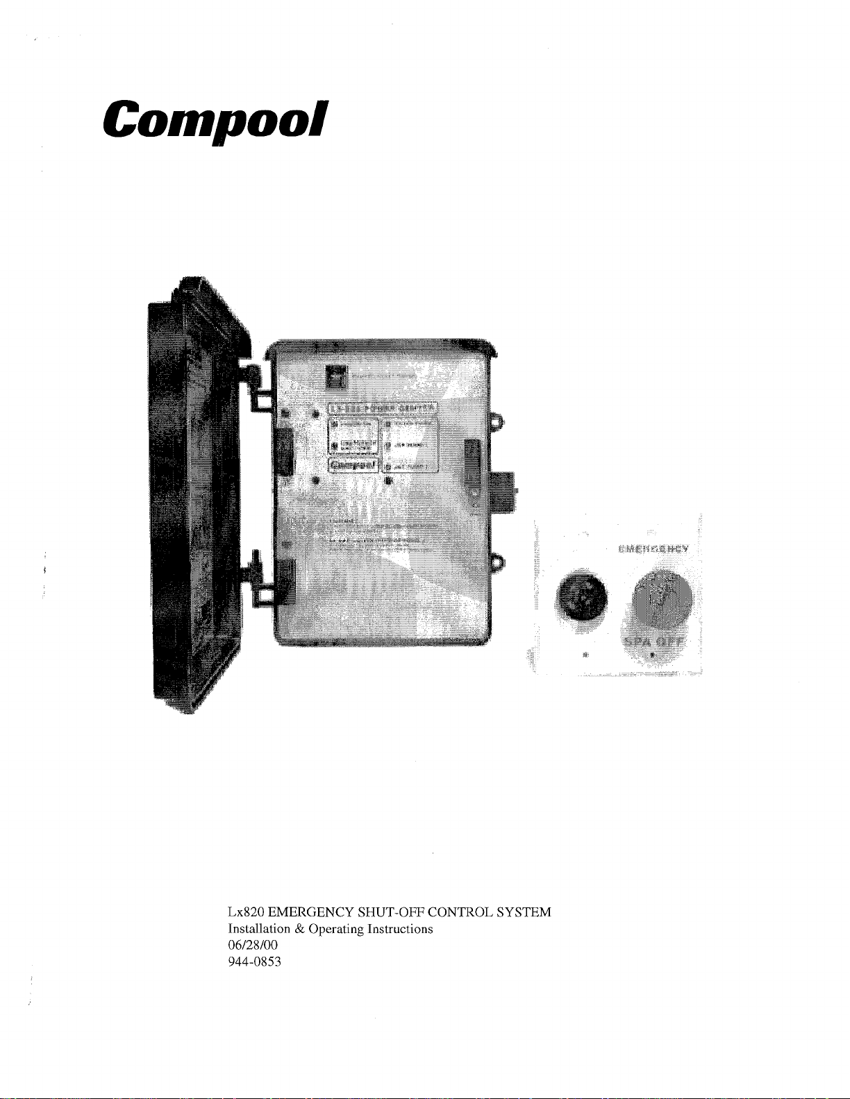
Lx820 EMERGENCY SHUT-OFF CONTROL SYSTEM
Installation & Operating Instructions
06/28/00
944-0853
Page 2

Page 3
Compool
Lx820
Table of Contents
Tableofcontents
Safety Notice 2
Important Safety Instructions 2
Introduction
Packagecontents
Electrical Schematic
Installation Instructions
Equipment Location 5
Low Voltage Cables
LX-820 Power Center
High Voltage Wiring
Transfomer
SpaFilterPump
JetPump
Additional Jet Pump Control
Pool Filter Pump Control
Front Panel Indicators 8
PowerOn
EmergencyShut-off
Filterpump
JetPump1
JetPump2
Push To Reset Power 8
........................................................
............................................................
.........................................
.............................................................
..................................................
................................................
....................................................
3
3
4
5
................................................
................................................
............................................
...............................................
....................................................
................................................
......................................................
......................................
.........................................
5
6
6
6
7
7
7
7
.....................................................
........................................................
................................................
.......................................................
........................................................
........................................................
...............................................
1
8
8
8
8
8
Warranty
...............................................................
9
Page 4
2
Safety Notice
Important Safety Instructions
When installing and using this electrical equipment, basic safety precautions should always be
followed, including the following:
READ AND FOLLOW ALL INSTRUCTIONS.
Compool
Lx820
WARNING
they are closely supervised at all times.
WARNING
A
green colored terminal (marked
LX-820
the
connected to the grounding means provided in the electrical supply service panel with a
continuous copper wire equivalent in size to the circuit conductors supplying this
equipment.
-
To reduce the risk of injury, do not permit children to use this product unless
-
Water in excess of
Power Center. To reduce the risk of electric shock, this terminal must be
100
degrees Fahrenheit may be hazardous to your health.
"G")
is located inside the high voltage compartment of
SAVE THESE INSTRUCTIONS.
Page 5

Compool
Lx820
Introduction
The
require an emergency shut-off switch. It is applicable to both new and existing installations.
In the event of an emergency, the spa can be shut off by pushing the red emergency button. This
action interrupts power to the filter pump, jet pump, and optional auxiliary pump or air blower.
Pulling the emergency button
the alarm.
Package Contents
The
LX-820 Power Center
LX820
LX82012
Control System offers economy and ease of installation for commercial spas which
back out will return the pumps to normal operation, and shut off
Emergency Shut-Off System includes the following components:
ESO-2 Emergency Shut-Off Switch
with
Alarm
Page 6

Electrical Schematic
EMERGENCY
SHUT
OFF
Spring-wound timer no1 ~nduded.
High Voltage
WmB
Low Voltage
Page 7

Compool
Lx820
Installation Instructions
Equipment Location
LX-820 Power Center
Select a convenient location to mount the LX-820
Power Center, making sure that the location is greater
than
5
feet from the Pool or Spa. Wall-mount the
Control, using appropriate screws through the three
external mounting points located on the side of the
enclosure.
5
ESO-2 Shut-off Switch
Select a convenient location to mount the ESO-2
Emergency Shut-Off Switch. Provide a double-gang
electrical box. The electrical box must be rated for
outdoor use if Emergency Shut-Off is located outside.
Provide and install a standard spring-wound timer for
the Jet Pump and a mechanical time clock for the Filler
Pump.
Note:
wound timer and mechanical time clock can be
rewired to the LX-820.
Low Voltage Cables
A separate 2-conductor 22AWG cable is required between the LX-820 and each of the
following:
1.
Emergency Shut-off Switch.
2. Spring-wound Timer for Jet Pump.
For retrofit applications, the existing spring-
3.
Optional second Spring-wound Timer.
Note:
Install cable, using plastic or metallic conduit where cables run underground.
Page 8

Compool
Lx820
LX-820
Power Center
Loosen LOCK SCREW on service panel of LX-820, and swing open to expose the high and low
voltage wiring compartments. Pull low voltage cables through hole on bottom left side of
820. Strip wires
1/4",
and connect to circuit board at appropriate screw terminals.
JET1 JET2
SPRING WOUND EMERGENCY
TIMER SHUT-OFF
SHUT
OFF
SWITCH
LX-
High Voltage Wiring
Transformer
The high voltage wiring section is located behind the service panel in the lower right side
compartment of the Solar Control. Holes are provided on bottom of enclosure for conduit
mounting. The Solar Control can be connected either to 1
Control should be wired so that it gets continuous power (connect to Line-Side of Time Clock
or directly to sub-panel).
ISVAC or 230VAC. The Solar
Page 9

Spa Filter Pump
Jet Pump
RELAY #l(plugged into circuit board at
SPA PUMP
socket).
Provide conduit and run the appropriate high
voltage wires from Filter Pump Time Clock
to the LX-820,
and from Filter Pump to the
LX-820.
At the LX-820, use wire nuts to make the
necessary connections to RELAY
Connect
Time Clock, and
black wires
red wires
to LOAD terminals of
REALY #2 (plugged into circuit board at
#I.
to Filter Pump.
JET1
socket).
Provide conduit and run the appropriate high voltage
wires from Jet Pump Circuit Breaker to the LX-820, and
from Jet Pump to the LX-820.
At the LX-820, use wire nuts to make necessary
connections lo REALY #2. Connect
LOAD terminals to Circuit Breaker, and
black wires
red wires
to
lo Jet
Pump.
n
W
5
TIME CLOCK
POWER FROM
CIRCUIT BREAKER
RELAY #2
n
W
K
POWER
2
2
a0
FROM
RELAY
#I
Go
PUMP CIRCUIT BREAKER
Additional Jet Pump Control
For systems which utilize a second jet pump or air blower, it is possible
to add a power relay so that this equipment can also be activated by the
Emergency Shut-off Switch. Install model RLY-SC Relay Kit in the high
voltage compartment in accordance with instructions provided, and plug
onto circuit board at
If a separate Spring-wound Timer is being added to control this
equipment, provide 2-conductor cable between Spring-wound Timer
and low voltage compartment of LX-820, and connect to circuit board at
JET2
screw terminals.
If only one Spring-wound Timer is being used to control all the
equipment, provide a jumper wire between screw terminals
on LX-820 circuit board.
Pool Filter Pump Control
It is possible to add a power relay so that the Pool Filter Pump will be inactivated by the
emergency Shut-off Switch. Install model RLY-SC Relay Kit in the high voltage compartment
of
lhe LX-820 in accordance with instructions provided, and plug onto circuit board at
PUMP
socket.
JETS2
socket.
#1
and
#3
#2
,,,, ,,,,
I
GNoll
SPRING-WOUND
TIMER
,,,,
m
SPRING-WOUND
TIMER
SHUT
,,,
I I
#2
SHUT
,,,
POOL
Page 10

Front Panel Indicators
Power On
When lit, indicates there is power to the control system.
Emergency Shut-off
When lit, indicates the Emergency Shut-off switch has been pressed.
Filter Pump
When lit, indicates the Filter Pump circuit(s) are enabled.
Compool
Lx820
Jet Pump
Jet Pump
1
When lit, indicates Jet Pump
2
When lit, indicates Jet Pump
Push To Reset Power
An internal circuit breaker protects the
A tripped breaker is indicated by a white tab. Check for short circuit conditions before resetting.
Push to reset.
Caution:
#I
is ON.
#2
is ON.
Do not attempt to pry out tab.
LX-820
transformer from electrical overload situations.
Page 11

Compool
---
Lx820
Warranty
Compool, Inc. warrants to Lhe purchaser of this electronic control system, for the period of one
year from the date of original purchase for use, that any defective product proved to be caused
by faulty workmanship or faulty material, will be repaired or replaced at Compool's option at
no charge, providing the product is returned to Compool with all transportation charges prepaid.
This warranty covers the LX-820 Power Center and Emergency Switch. It extends to the first
retail purchaser and any subsequent owners of
the system.
This limited warranty applies only to
conlrols which have been installed and maintained in strict
accordance with installation and operating instructions provided by Compool, Inc., using
installation hardware supplied
and/or recommended in writing by Compool, and to controls
which have been connected to the correct supply voltage.
This
limiled warranty does not apply to any controls which have been repaired or altered by
anyone other than Compool or a person authorized by it; or which have been subject to misuse,
neglect or accident; or which have been damaged by wind, rain, lightning, freezing or other
cause, thing, person, or act of God; or which have been subject to damage in transit, during
installation, or by someone other than Compool, Inc.; or which have been damaged because of
a defect in a
componenl or part which is not part of the Compool Control System; or upon which
the serial number or manufacture date has been altered, effaced or removed.
This warranty gives you specific legal rights and you may also have other rights which vary
from State to State. Compool, Inc. does not authorize
any person to create any other obligation
or liability in connection with Compool controls.
Compool, Inc. makes no warranty of merchantability or fitness for any use. Any implied
warranty applicable
Lo Compool controls is limited in duration to the duration of this written
warranty. Unless state law provides otherwise, Compool, Inc. shall not be liable for
consequential or incidental damages resulting from breach of this written warranty or any
implied warranty, or any inconvenience, loss of time, or incidental expenses such as telephone
calls.
Compool, Inc. shall not be liable for any labor charges associated with the removal or
reinstallation of any so-claimed defective products.
To exercise this warranty, send defective parts, with copy of dated receipt and a brief description
of the problems encountered, postage prepaid, to:
Compool, Inc.
599 Fairchild Drive
Mountain View, California 94043
For questions, repairs, replacement parts, or information on possible Authorized Service
Centers within your vicinity call:
Compool, 800-458-2201 or 650-964-2201, Monday
-
Friday, 8:00 - 5:00 Pacific Time.
Or visit us on the internet at compool.com
 Loading...