

Page 1

LX-80 COMMERCIAL POOL & SPA CONTROL
INSTALLATION INSTRUCTIONS
IMPORTANT SAFETY PRECAUTIONS:
All wiring must be performed by a qualified electrician.
Basic safety precautions and local codes should be observed when
installing and using this electrical equipment.
EQUIPMENT LOCATION:
ALL ELECTRICAL EQUIPMENT MUST BE LOCA TED FIVE FEET OR
MORE FROM THE W A TER’S EDGE.
Select a convenient location to mount the LX-80 Control Center .
Wall-mount the LX-80, using appropriate screws through the three
external mounting points located on the side of the enclosure.
Do not drill and mount from inside enclosure.
Install to provide drainage of compartment for electrical components.
Select a convenient location to mount the RCS-1 Spa Jets Switch and the
ESO-1 or ESO-2 Emergency Shut-off Switch.
Provide a single-gang electrical box for the RCS-1.
Provide a single-gang electrical box for the ESO-1 (without alarm), or a
double-gang electrical box for the ESO-2 (with alarm).
Electrical boxes must be rated for outdoor use if Switches are to be
located outside.
LOW VOL TAGE CABLES:
A Separate 2-conductor 22AWG cable is required betw een the LX-80 and
each of the following:
1. Spa Jets Switch.
2. Emergency Shut-off Switch.
3. Pool Gas Heater .
4. Spa Gas Heater.
Install cable, using plastic or metallic conduit where cables run
underground, through concrete, etc.
CAUTION: Never install low voltage and high v oltage wires in the
same conduit.
1
Page 2

LX-80 CONTROL CENTER :
Loosen LOCK SCREW on hinged faceplate located in left-side of LX-80,
and swing open to expose the lo w voltage wiring compartment.
Pull low voltage cables through holes in bottom left-side of LX-80.
Strip wires ¼” and connect to circuit board at appropriate screw
terminals in accordance with low voltage wiring diagram located inside
enclosure cover .
NOTE:
terminal can be plugged from the circuit board without disconnecting wires.
For the conv enience of the serviceperson, the 10 position screw
RCS-1 SPA JETS SWITCH :
At the LX-80, connect 2-conductor cable form the Spa Jets Switch to
circuit board at REM 1 screw terminals.
At the Spa Jets Switch location, strip insulation of each wire ¼” and
connect to screw terminals #3 and #4 on switch contact block.
There is no polarity , so color-coding is unimportant.
Position gasket over back of switchplate, and mount to electrical box,
using mounting screws provided.
EMERGENCY SHUT-OFF SWITCH :
At the LX-80, connect 2-conductor cable for the Emergency Shut-off
Switch to circuit board at SHUT OFF screw terminals.
If model ESO-2 (with alarm) is being installed, connect green wire to the
upper screw terminal and red wire to the lower screw terminal.
If model ESO-1 is being installed, color-coding is unimportant.
At the Emergency Shut-off Switch, strip insulation of each wire ¼”, and
make appropriate connections to screw terminals #1 and #2 on switch
contact block:
For ESO-2, connect red wire to screw terminal #2 and green wire to
screw terminal #1, but do not disconnect factory wiring between
contact block and alarm.
For ESO-1, color-coding in unimportant.
Position gasket over back of switchplate, and mount to electrical box
using mounting screws provided.
CAUTION: If Emergency Shut-Off Switch is not installed, then a jumper
wire must be connected between “SHUT OFF” screw terminals on
circuit board.
2
Page 3
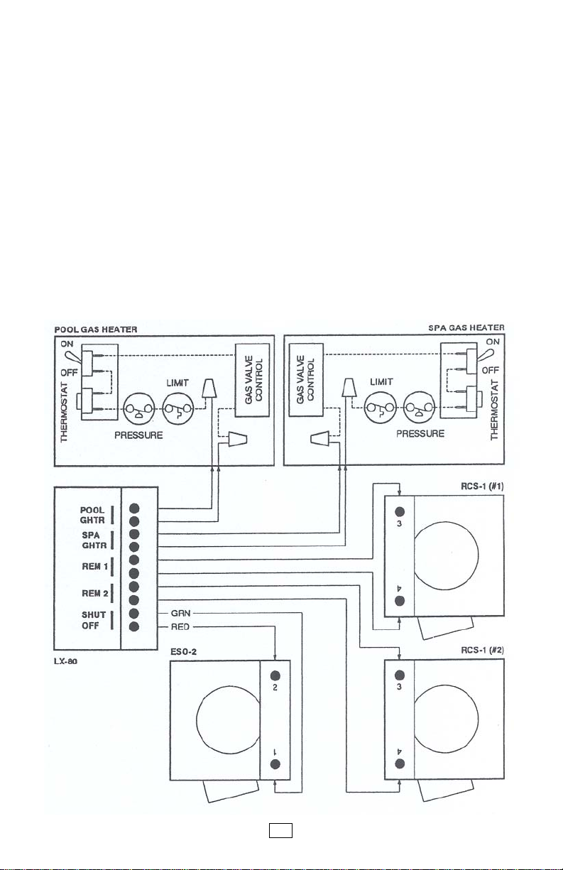
FIREMAN’S SWITCH CONNECTIONS :
At the LX-80, connect 2-conductor cables from the P ool and Spa Gas
Heaters to circuit board at the appropriate screw terminals:
Connect Pool heater to POOL GHTR screw terminals, and Spa Heater
to SPA GHTR screw terminals.
Inside each gas heater (pool and spa), find fireman’s s witch wire nut, or
interrupt wire between thermostat and gas valve, and connect 2-conductor
cable with wire nuts, in accordance with wiring diagram.
Do not disconnect high limit and pressure switches.
CAUTION: If optional T emper ature Control Modules (model MOD-SOL) are
being used, heater thermostats must be overridden. To accomplish this , turn
thermostat switch to “ON”, “HIGH” or “SPA” (depending on the type of heater
used), and set dial to highest temperature possible.
LOW VOLT AGE WIRING:
3
Page 4

HIGH VOL TAGE WIRING :
All high voltage connections are made to terminal blocks, which are
located behind service panel in right-side compartment of LX-80.
A wiring label is located adjacent to terminal blocks.
Knock-out holes are provided on bottom of enclosure for conduit mounting.
Install an electrical sub-panel with separate breakers for each load.
Provide a separate circuit breaker (if possible) to power the system.
Either 115V A C or 230VAC can be used. System dra ws less than 1 amp .
Run wires from circuit breaker to high voltage compartment of LX-80, and
connect to top terminal block which is marked “SYSTEM PO WER”.
Install 2 jumpers for 115V, or 1 jumper for 230V wiring, according to
wiring label.
Provide independent circuit breakers (if possible) f or R1 (POOL FL TR),
R2 (SP A FLTR) and R3 (JETS 1).
Run wires from breakers to high voltage compartment of LX-80, and
connect to LINE 1 and LINE 2 terminals of appropriate terminal block.
Connect pumps and other high voltage equipment to LOAD 1 and LOAD 2
terminals at appropriate terminal block.
Each individual terminal block can be wired for either 115VAC or 230V A C.
For 115V equipment, only half of the terminal block will be used.
CAUTION: If pumps exceed 2½ HP, the high voltage relay should be
used to energize a magnetic starter.
NOTE: Circuits for R4, R5, R6, and R7 are optional and require additional
relay kits (model RLY-LX).
A Relay Allocation Chart is provided inside enclosure cover for the
serviceperson’s con venience.
To reduce the risk of electric shock, provide a continuous green insulated
copper wire, no smaller than #12AWG, betw een grounding bus of LX-80
and grounding terminal of electrical supply panel.
Additionally , a wire connector is provided f or bonding to local ground
points, To further reduce the risk of electric shock, this connector should
be bonded with a #8AWG copper wire to any metal ladders , water pipes,
or other metal within five feet of the pool or spa.
4
Page 5

SYSTEMS OPTIONS
TEMPERATURE CONTROL MODULES :
It is possible to provide precision thermostatic control of the pool and
spa heaters by adding T emperature Control Modules (model MOD-SOL)
at the LX-80. A separate Module should be pr ovided for each heater .
Additionally , each Module contains a b uilt-in solar control for the optional
control of a booster pump or motorized valve, or both. This enables a
separate solar system for each body of water .
Install MOD-SOL in accordance with instructions provided.
MULTIPLE SPA JET PUMPS OR BLOWERS :
The standard system is provided with a relay to activate one jet pump or
air blower . Howev er , a combination of up to 4 jet pumps and / or air
blowers can be controlled by the Spa Jets Switch. A separate relay
(model RLY-LX) should be added for each pump.
Install RLY-LX in accordance with instructions provided.
A second JETS 1 relay socket is provided on the circuit board.
If more that 2 pumps are being used, install an adapter (model RYA-LX)
in which to plug two relays from one relay socket.
DUAL REMOTE CONTROLS :
A second Spa Jets Switch (model RCS-1) may be added to the system to
activate up to 2 more pumps.
Install RCS-1 in accordance with previous instructions, and connect
2-conductor cable to LX-80 circuit board at REM 2 screw terminals.
Additonal relays (model RLY-LX) should be installed for each pump .
Plug RLY-LX into LX-80 circuit board at JETS 2 relay socket(s).
POOL CHLORINE PUMP :
A pool filter pump is less than 2HP, the POOL FLTR relay (R1) can be
used to actuate a separate chlorine pump.
If pool filter pump is 2HP to 2½HP, a separate rela y (model RLY-LX)
should be used to actuate the chlorine pump.
Install RLY-LX in accordance with instructions, and plug into circuit board
at POOL ORP relay socket.
SPA CHLORINE PUMP :
If spa filter pump is less than 2HP, the SPA FLTR relay (R2) can be used
to actuate a separate chlorine pump.
If spa filter pump is 2HP to 2½HP, a separate rela y (model RLY-LX)
should be used to actuate the chlorine pump.
Use an adapter (model RYA-LX) in order to plug both relays into the
circuit board at SP A FLTR relay socket.
5
Page 6

OPERATING INSTRUCTIONS
POOL/SP A TIMER
T o set the correct time of day :
Rotate the dial in a clockwise direction until the hours and minutes line-up
with the white arrow at eight o’clock position on the clock face.
Pay particular attention to the AM and PM sections of the dial.
T o program operating time(s) :
Depress number of sections around the perimeter of the dial by pushing
towards the center . For each section depressed, the equipment will operate
for 15 minutes.
POOL/SPA FILTER
NOTE: Whenever filter pump is running, water will automatically heat
up to the preset temperature.
Service Switch positions :
TIMER Keep in this position f or normal system operation.
OFF Turns filter pump off (for service purpose only).
ON T urns filter pump on (for service purpose only).
T o override Fireman’ s Switch :
Whenever the timer shuts off, the filter pump will continue to run for an
additional ten minutes to cool down the heater and protect the equipment
from overheating.
In order to cancel this “delay” (for service purpose), switch to OFF and then
back to TIMER position.
Status Light :
PUMP ON Indicates whenever filter pump is running.
SPA JETS
Service Switch positions :
40 MIN Remote Switch will activate jets for 40 minute cycle.
20 MIN Remote Switch will activate jets for 20 minute cycle.
TEST Remote Switch will activate jets for 5 seconds (for service purposes).
Status Lights :
JETS 1 Indicates whenever Remote Switch is running.
JETS 2 Indicates whenever optional second Remote Switch is running.
6
Page 7

SPA PRIORITY
Service Switch positions :
TIMER Spa jets, filter pump, and heater will operate only when
SP A TIMER is on.
Whenever SPA TIMER is off , Remote Switch is disab led.
REMOTES Spa jets, filter pump and heater will operate whenever
Remote Switch is activated, regardless of SP A TIMER position.
POOL/SPA HEA TING (Optional)
Service Switch positions :
SOLAR Allows heating with solar only.
SOL PREF Allows preferential heating with solar , but automatically
switches to conventional heating when solar energy is
unavailable.
HEATER Allows heating with gas or electric heater only .
OFF Allows no heating.
Status Lights :
HEA TER ON Indicates whenever heater is on.
SOLAR ON Indicates whenever solar is on.
Pool and Spa Thermostats :
Set THERMOSTAT dial(s) to the desired water temperature.
NOTE: Make sure that separate thermostat on heater is turned all the way up.
If optional T emperature Control Module is not used, use separate thermostat on heater to set desired water temperature.
REMOTE SWITCH
T o operate spa :
Push Spa Jets button once to activate spa.
T o turn spa off :
Spa will automatically switch off at the end of its cycle.
To turn spa off during its cycle, push Spa Jets button a second time.
A second Remote Switch may be used to control additional jets.
This optional SPA JETS button will not activate the filter pump or heater .
EMERGENCY SHUT-OFF SWITCH
In the event of an emergency :
Push Red button to automatically shut-off all spa equipment.
T o reset :
Pull out Red button in order to reset spa equipment.
7
Page 8

ONE YEAR LIMITED WARRANTY
Pentair P ool Products warrants to the purchaser of the Electronic Control
System, for a period of one (1) year for the date of original purchase for use,
that any defective product proved to be caused by faulty workmanship for
faulty material, will be repaired or replaced at Pentair P ool Products option f or
no charge, providing the product is returned to Pentair P ool Products, with all
transportation charges prepaid.
No allowances will be made for labor for the removal or reinstallation of any
so-claimed defective products.
This warranty cov ers the Control Center , Spa Jets Switch and Emergency
Shut-off Switch, including all components and parts. It extends to the
consumer who made the original retail purchase only and is not enforceable
by any other party.
This limited warranty applies only to Controls which have been installed and
maintained in strict accordance with installation and operating instructions
provided by P entair Pool Products , using installation hardware supplied and/or
recommended in writing by Pentair P ool Products, and to Controls which ha ve
been connected to the correct supply voltage.
This limited warranty does not apply to any Controls which have been repaired
or altered by anyone other than P entair P ool Products or a person authorized
by it; or which have been subject to misuse, neglect, or accident; or which
have been damaged by wind, freezing or other cause, thing, person or act of
God; or which have been subject to damage in transit, during installation, or by
someone other than Pentair P ool Products; or which have been damaged
because of a defect in a component or part which is not part of the Compool
Control System; or upon which the serial number or manufacture date has
been altered, effaced or removed.
Unless state law provides otherwise, P entair P ool Products shall not be liable
for consequential or incidental damages resulting from breach of this written
warranty or any implied warr anty, or for any inconv enience, loss of time , or
incidental expenses such as telephone calls.
To exercise this warr anty, send defective unit with copy of dated receipt and
a brief description of the problems encountered, postage prepaid, to:
PENT AIR POOL PRODUCTS
10951 West Los Angeles A ve., Moorpark, CA 93021 • (805) 523-2400
941-0688
8
 Loading...