

STA-RITE JWPA5DL, JWPA5EL, JWPA5FL, JWPA5E7, JWPA5F7L Owner's Manual
...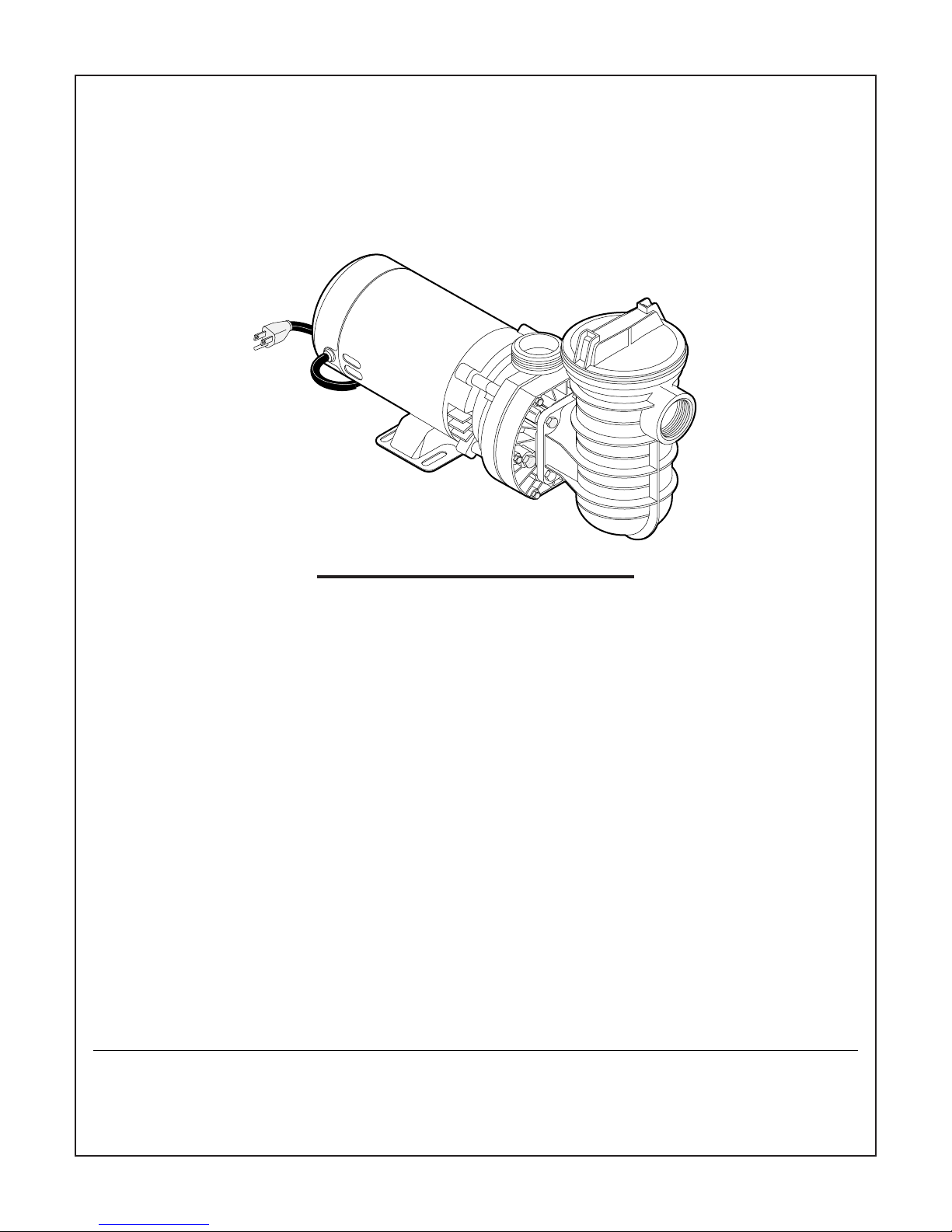
WATERFORD SYSTEMS
SWIMMING POOL PUMP
O W N E R’ S M A N U A L
INSTALLATION, OPERATION & PARTS
MODELS
1/2 HP 3/4 HP 1 HP 1-1/2 HP
JWPA5C JWPA5D JWPA5E JWPA5F
JWPA5DL JWPA5EL JWPA5FL
JWPA5DL JWPA5E7 JWPA5F7L
JWPA5D7L JWPA5E7L
3/4 HP/2 SPEED 1 HP/2 SPEED 1-1/2 HP/2 SPEED
JWPXYD JWPAXYE JWPA5YFL
JWPXYDL JWPAXYEL JWPA5YF7L
JWPA5YEL
JWPA5YE7L
JWPA5Y7EL
Sta-Rite Pool/Spa Group
293 Wright Street, Delavan, WI 53115
International: 262-728-5551, FAX: 262-728-7550
www.starite.com
Union City, TN • Delavan, WI • Mississauga, Ont. • Murrieta, CA
© 2004, Sta-Rite Industries Printed in U.S.A. S302 (Rev. 2/10/04)
This manual should be furnished to
the end user of this pump; its use
will reduce service calls and chance
of injury and will lengthen pump life.
1922 0895A
2
IMPORTANT
SAFETY
INSTRUCTIONS
Always follow basic safety precautions with this equipment,
including the following.
To reduce the risk
of injury, do not permit children
to use this product unless they
are closely supervised at all
times.
SAVE THESE
INSTRUCTIONS
WATERFORD SYSTEMS
SWIMMING POOL PUMP
To avoid unneeded service calls, prevent possible injuries, and get the most
out of your pump, READ THIS MANUAL CAREFULLY!
The Sta-Rite ‘JWP’ Series Above Ground Pool Pump:
• Is designed to circulate water in swimming pools.
• Is an excellent performer; durable, reliable.
Table of Contents
Safety Instructions ..................................................................................2-3
Installation...............................................................................................3-5
Electrical .................................................................................................5-6
Operation ...................................................................................................7
Storage/Winterizing ....................................................................................8
Pump Service..............................................................................................9
Troubleshooting Guide .............................................................................10
Repair Parts List...................................................................................11-12
Warranty...................................................................................................16
READ AND FOLLOW
SAFETY INSTRUCTIONS!
This is the safety alert symbol. When you see this symbol on your system or in this manual, look for one of the following signal words and
be alert to the potential for personal injury.
warns about hazards that will cause death, serious personal
injury, or major property damage if ignored.
warns about hazards that can cause death, serious personal
injury, or major property damage if ignored.
warns about hazards that will or can cause minor personal
injury or property damage if ignored.
NOTICE indicates special instructions not related to hazards.
Carefully read and follow all safety instructions in this manual and on equipment. Keep safety labels in good condition; replace if missing or damaged.

3
Incorrectly installed or tested equipment may fail, causing
severe injury or property damage.
Read and follow instructions in owner's manual when installing
and operating equipment. Have a trained pool professional per-
form all pressure tests.
1. Do not connect system to a high pressure or city water system.
2. Use equipment only in a pool or spa installation.
3. Trapped air in system can cause explosion. BE SURE all air is out of system
before operating or testing equipment.
Before pressure testing, make the following safety checks:
Check all clamps, bolts, lids, and system accessories before testing.
Release all air in system before testing.
Tighten Sta-Rite trap lids to 30 ft. lbs. (4.1 kg-m) torque for testing.
Water pressure for test must be less than 25 PSI (7.5 kg/cm
2
).
Water Temperature for test must be less than 100oF. (38oC).
Limit test to 24 hours. After test, visually check system to be sure it is ready
for operation. Remove trap lid and retighten hand tight only.
NOTICE: These parameters apply to Sta-Rite equipment only. For
non-Sta-Rite equipment, consult manufacturer.
Motor normally operates at high temperature and will be too
hot to touch. It is protected from heat damage during operation by an automatic internal cutoff switch. Before handling pump or motor, stop motor and
allow it to cool for 20 minutes.
INSTALLATION
Installation and wiring of pump should only be done by qualified, licensed
personnel.
For self-priming pumps, locate the pump as close as possible to the pool and
not more than 3 feet above pool water level.
For ease of pump/motor removal, install pipe unions on the suction and discharge pipes close to pump.
Pump mount must:
Be solid - Level - Rigid - Vibration free. (To reduce vibration and pipe stress,
bolt pump to mount.)
Allow pump suction inlet height to be at or below water level in pool.
Allow use of short, direct suction pipe (To reduce friction losses).
Allow for gate valves in suction and discharge piping.
Have adequate floor drainage to prevent flooding.
Be protected from excess moisture.
Allow adequate access for servicing pump and piping.
NOTICE: Use Teflon tape or Plasto-Joint Stik
1
for making all threaded connections to the pump. Do not use pipe dope; pipe dope will cause stress
cracking in the pump.
1
Lake Chemical Co., Chicago, Illinois
NOTICE: Pump suction and discharge connections have molded in thread
stops. DO NOT try to screw pipe in beyond these stops. Tighten the
pump/trap fittings only as much as it is required to insure a tight connection
(1-1/2 turns past hand tight is sufficient). Overtightening may damage the
pump trap. Use care when using teflon tape as friction is reduced considerably; do not overtighten connections or damage may occur.
Teflon Taping Instructions:
Use only new or clean PVC pipe fittings.
Wrap male pipe threads with one to two layers of Teflon tape. Cover entire
threaded portion of pipe.
Do not overtighten or tighten past thread stop in pump port!
If leaks occur, remove pipe, clean off old tape, rewrap with one to two addi-
tional layers of tape and remake the connection.
NOTICE: Support all piping connected with pump!
Piping:
Use at least 1-1/2" (38mm) IPS PVC pipe with 5” (127mm) trap. Increase size
if a long run is needed.
To avoid strains on the pump, support both suction and discharge pipes
independently. Place these supports near the pump.
To avoid a strain left by a gap at the last connection, start all piping at the
pump and run pipe away from the pump.
Never use a suction pipe smaller than pump suction connection.
To avoid airlocking, slope suction pipe slightly upward toward the pump.
NOTICE: To prevent flooding when removing pump for service, all flooded
suction systems must have gate valves in suction and discharge pipes.
Plastic pipe will expand and contract as the temperature changes. To allow
for this, use an expansion joint or flexible piping.
Union provided for pump discharge port. Use as follows for leak-free con-
nection to pump:
1. O-Ring and sealing surfaces must be clean.
2. Assemble handtight only! (NO WRENCHES!)
3. NO pipe compound or teflon tape on union.
4. Bond pipe to union with PVC cement.
Use PVC cement only in a well ventilated area away from flame;
FOLLOW MANUFACTURER’S INSTRUCTIONS!
4
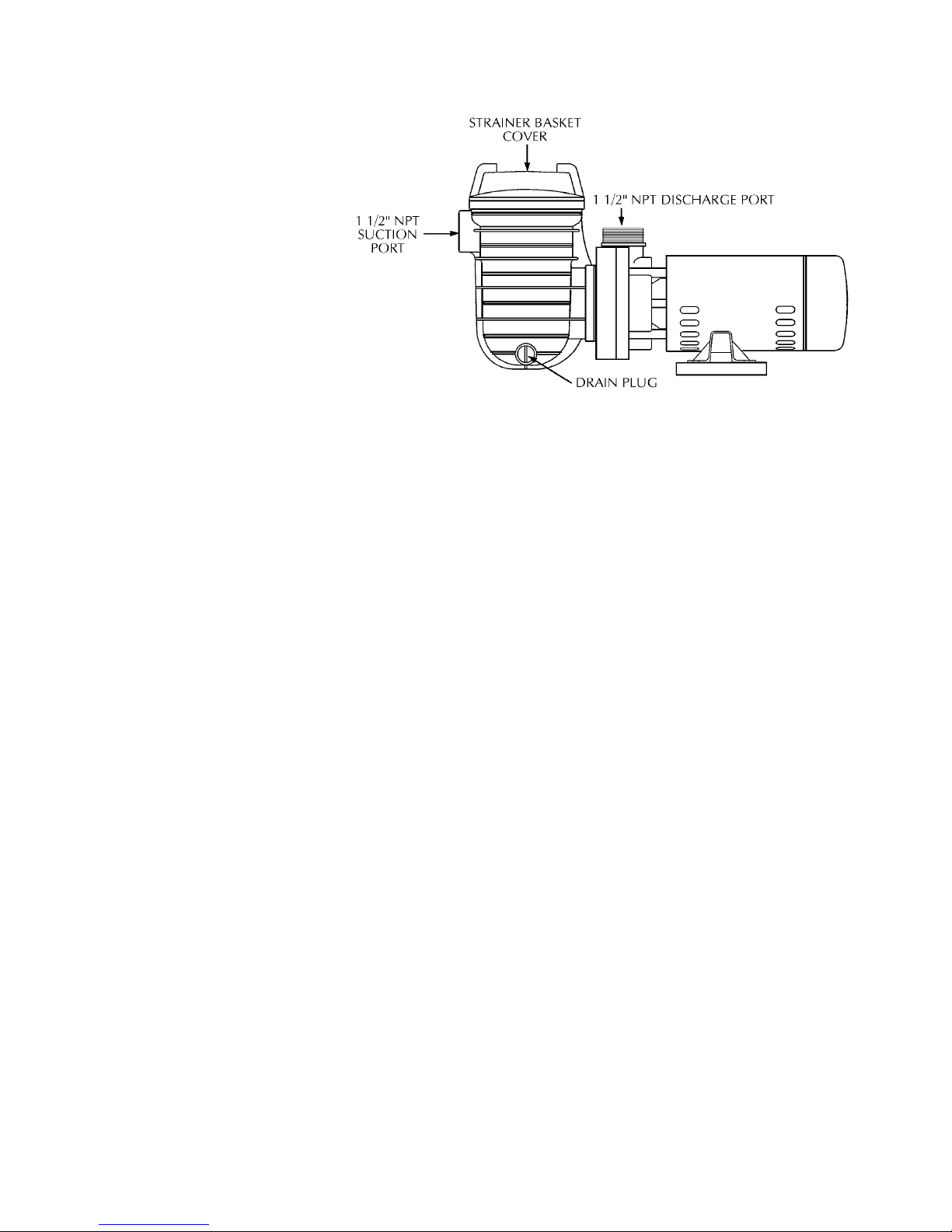
FIGURE 1
Fittings:
Fittings restrict flow; for best efficiency use fewest possible fittings.
Avoid fittings which could cause an air trap.
Pool fittings must conform to International Association of Plumbing and
Mechanical Officials (IAPMO) standards.
Use only non-entrapping suction fitting or double suction (skimmer and
main drain).
ELECTRICAL
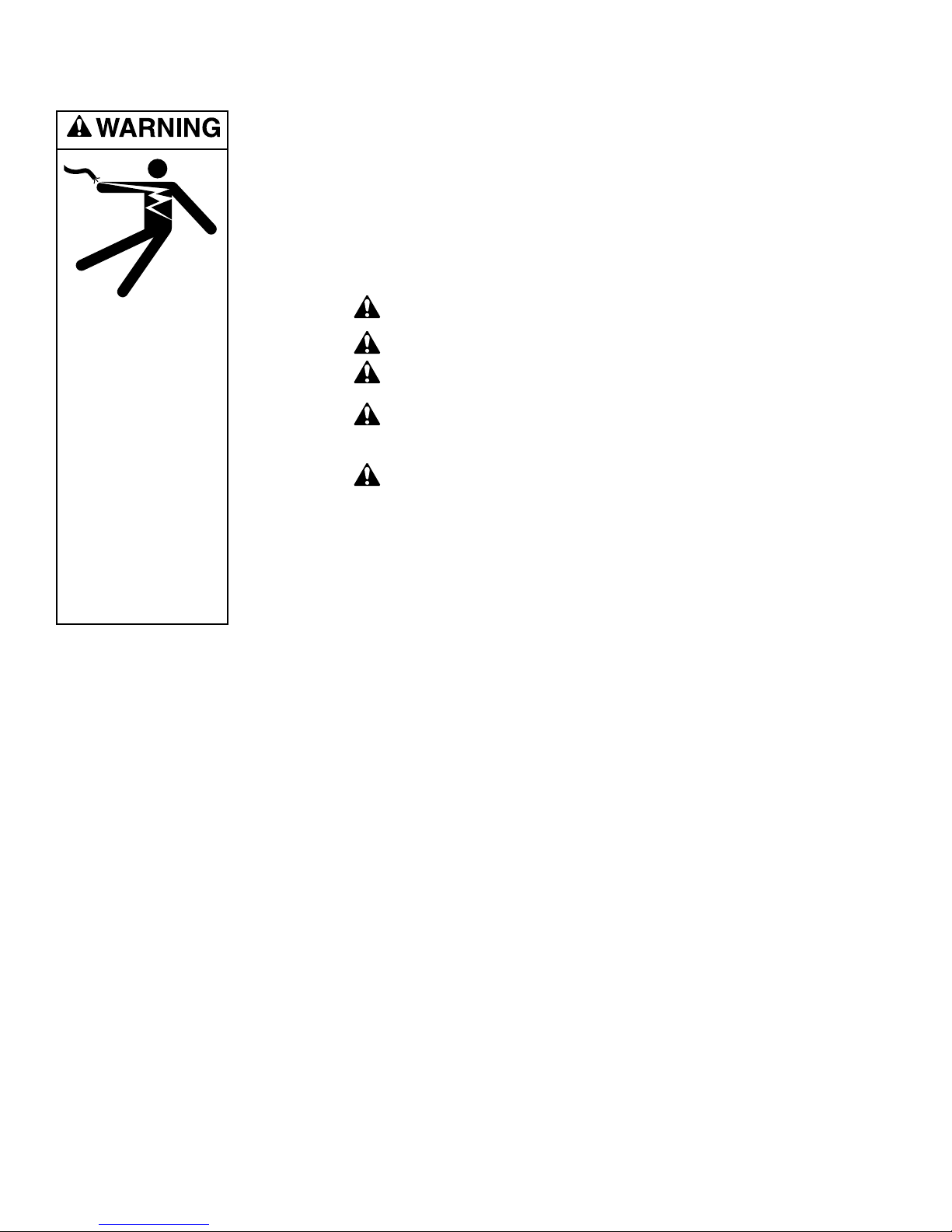
Ground motor before connecting to electrical power supply. Failure
to ground motor can cause severe or fatal electrical shock hazard.
Do not ground to a gas supply line.
To avoid dangerous or fatal electrical shock, turn OFF power to
motor before working on electrical connections.
Ground Fault Circuit Interrupter (GFCI) tripping indicates an electri-
cal problem. If GFCI trips and will not reset, have a qualified
electrician inspect and repair electrical system.
Exactly match supply voltage to nameplate voltage! Incorrect voltage
can cause fire or seriously damage motor and voids warranty.
If in doubt consult a licensed electrician.
Voltage:
Voltage at motor must be not more than 10% above or below motor nameplate rated voltage or motor may overheat, causing overload tripping and
reduced component life. If voltage is less than 90% or more than 110% of
rated voltage when motor is running at full load, consult power company.
Grounding/Bonding:
Install, ground, bond and wire motor according to local or National
Electrical Code requirements.
Permanently ground motor; use size and type wire required by code.
Ground connection must be made to green grounding terminal under motor
canopy or access plate (see Figure 2A).
Connect motor ground terminal to electrical service ground.
Install and bond pump according to local codes and ordinances; use bond-
ing lug on motor (see Figure 2A). Use solid copper conductor No. 8 AWG
(8.4 sq. mm) or larger.
Connect a No. 8 AWG (8.4 sq. mm) solid copper bonding wire to the pressure wire connector provided on the motor housing and to all metal parts of
the swimming pool, spa, or hot tub and to all electrical equipment, metal
piping or conduit within 5 feet (1.5m) of the inside walls of the swimming
pool, spa or hot tub.
5
Hazardous voltage.
Can shock, burn, or
kill.
• Disconnect power
to pump before working on pump
or motor.
• Do not alter cord
or plug on cordconnected models.
• Connect plug-in
models only to a
grounded, GFCI
protected outlet, that
meets code for pool
installations.
• Ground hard-wired
models before
connecting to
power supply.
 Loading...