

Page 1
293 Wright Street, Delavan, WI 53115
Phone: 1-888-782-7483
Fax: 1-800-426-9446
Web Site: Sta-Rite.com
OWNER’S MANUAL
Portable Utility Water Pump
© 2011 S930 (5/31/2011)
DPC
Installation/Operation/Parts
For further operating, installation, or
maintenance assistance:
Call 1-888-782-7483
Page 2
Safety 2
Important Safety Instructions
SAVE THESE INSTRUCTIONS - This manual contains
important instructions that should be followed during
installation, operation, and maintenance of the product.
Save this manual for future reference.
This is the safety alert symbol. When you see this
symbol on your pump or in this manual, look for one of
the following signal words and be alert to the potential
for personal injury!
indicates a hazard which, if not avoided, will
result in death or serious injury.
indicates a hazard which, if not avoided,
could result in death or serious injury.
indicates a hazard which, if not avoided,
could result in minor or moderate injury.
NOTICE
Carefully read and follow all safety instructions in this
manual and on pump.
Keep safety labels in good condition.
Replace missing or damaged safety labels.
Make workshops childproof; use padlocks and master
switches; remove starter keys.
General Safety
1. To avoid risk of serious bodily injury and property
2. Follow local and/or national plumbing and electrical
3. Hazardous Pressure. The pump body
4. Never run the pump dry. To do so can damage
5. Risk of fire or explosion. To avoid risk
6. Burn Hazard. If water is trapped in the
7. Burn Hazard. Do not touch an
addresses practices not related to personal injury.
damage, read the safety instructions carefully before
installing this pump.
codes when installing the pump.
may explode if used as a booster pump unless a
relief valve capable of passing the full pump flow at
75 PSI (517 kPa) is installed.
internal parts, overheat pump (which can cause
burns to people handling or servicing pump), and
will void warranty.
of fire and explosion, Pump Water Only with this
pump. Do not use this pump in an atmosphere that
might contain flammable fumes or vapors.
pump during operation it may turn to steam. Trapped
steam can lead to an explosion and burns. Never run
the pump with the outlet closed or obstructed.
operating motor. Modern motors can operate at
high temperatures. To avoid burns when servicing
the pump, allow it to cool for 20 minutes after shutdown before handling.
Electrical Safety
The pump is supplied with a 3-conductor grounding
type cord. Connect only to a properly grounded,
GFCI protected outlet. Do not lift the pump by the
electricalcord.
Hazardous voltage. Can shock, burn or
cause death. Ground pump before connecting to power
supply. Disconnect power before working on pump,
motor ortank.
The pump is non-submersible. Keep the motor dry at all
times. Do not wash the motor. Do not immerse. Protect
the motor from wet weather.
If using an extension cord, use only a UL approved
indoor/outdoor, 3-wire, grounding type cord. Do not
allow any part of the cord or the receptacle ends to sit in
water or in damp locations.
Unplug the pump before servicing. To avoid fatal shocks,
proceed as follows if the pump needs servicing.
A. Disconnect the power to the pump outlet box before
pulling the pump plug. After the plug is pulled, let
the pump cool for 20 minutes before attempting to
work on it.
B. Take extreme care when changing fuses. To reduce
the chance of fatal electrical shock, DO NOT stand
in water or put your finger in the fuse socket.
C. Ground electrical outlet box.
D. Plug pump into a Ground Fault Circuit Interrupter
(GFCI) protected grounded outlet only.
Page 3

Warranty 3
Retain Original Receipt For Your Records
Limited Warranty
STA-RITE warrants to the original consumer purchaser (“Purchaser” or “You”) of the products listed below, that they will be free
from defects in material and workmanship for the Warranty Period shown below.
Product Warranty Period
Water Systems Products — jet pumps, small centrifugal pumps,
submersible pumps and related accessories
Pro-Source™ Composite Tanks 5 years from date of original installation
Pro-Source™ Steel Pressure Tanks 5 years from date of original installation
Pro-Source™ Epoxy-Lined Tanks 3 years from date of original installation
Sump/Sewage/Effluent Products 12 months from date of original installation, or
Our warranty will not apply to any product that, in our sole judgement, has been subject to negligence, misapplication, improper
installation, or improper maintenance. Without limiting the foregoing, operating a three phase motor with single phase power
through a phase converter will void the warranty. Note also that three phase motors must be protected by three-leg, ambient
compensated, extra-quick trip overload relays of the recommended size or the warranty is void.
Your only remedy, and STA-RITE’s only duty, is that STA-RITE repair or replace defective products (at STA-RITE’s choice). You must
pay all labor and shipping charges associated with this warranty and must request warranty service through the installing dealer
as soon as a problem is discovered. No request for service will be accepted if received after the Warranty Period has expired. This
warranty is not transferable.
STA-RITE SHALL NOT BE LIABLE FOR ANY CONSEQUENTIAL, INCIDENTAL, OR CONTINGENT DAMAGES WHATSOEVER.
THE FOREGOING WARRANTIES ARE EXCLUSIVE AND IN LIEU OF ALL OTHER EXPRESS AND IMPLIED WARRANTIES,
INCLUDING BUT NOT LIMITED TO THE IMPLIED WARRANTIES OF MERCHANTABILITY AND FITNESS FOR A PARTICULAR
PURPOSE. THE FOREGOING WARRANTIES SHALL NOT EXTEND BEYOND THE DURATION EXPRESSLY PROVIDED HEREIN.
Some states do not allow the exclusion or limitation of incidental or consequential damages or limitations on the duration of an
implied warranty, so the above limitations or exclusions may not apply to You. This warranty gives You specific legal rights and
You may also have other rights which vary from state to state.
This warranty supersedes and replaces all previous warranty publications.
STA-RITE INDUSTRIES
293 Wright Street • Delavan, WI U.S.A. 53115
Phone: 1-888-782-7483 • Fax: 1-800-426-9446 • Web Site: Sta-Rite.com
whichever occurs first:
12 months from date of original installation,
or 18 months from date of manufacture
18 months from date of manufacture
Page 4
Installation 4
Before You Install Your Pump
Pump clean water only with this pump.
NOTICE: This unit is not designed for applications
involving salt water or brine! Use with salt water or brine
will void warranty.
To avoid clogging the pump and damaging the shaft
seal, do not pump water containing solids, foreign
material, sand, silt, or abrasives. Always have the suction
strainer installed when the pump is operating. Failure
to use a strainer may cause the pump to fail and void
thewarranty.
Clean the strainer and flush out the pump after each
use. Make sure all of the hose and pipe connections
in the suction line are tight. An air leak in the suction
line will prevent the pump from priming and reduce
pumpperformance.
Tighten all of the piping joints to the pump hand tight
+1-1/2 turns only. Overtightening may break the pump
and will void the warranty.
Do not allow the pump or any system component to
freeze. Freezing will void the warranty.
Periodically inspect the pump and the
systemcomponents.
Priming The Pump
All suction connections must be airtight. Make sure the
suction lift is not more than 25 feet (7.6M).
NOTICE: ‘Priming’ refers to the pump expelling all air in
the system and beginning to move water from its source
out into the system. It does not refer only to pouring
water into the pump (although pouring water in is
usually the first step).
Burn Hazard. NEVER run the pump dry.
Running the pump without water may cause pump to
overheat, damaging seal and possibly causing burns
to persons handling the pump. Running pump without
water can damage the impeller and may damage the
seal, causing leaking or flooding, and will void the
warranty. Fill the pump with water before starting it.
Follow the steps below.
1. Remove the priming plug.
2. Make sure the suction and the discharge valves
and any hoses on the discharge side of the pump
areopen.
3. Fill the pump and suction pipe with water
4. Replace the priming plug, using 1Teflon™ tape
or Teflon™ based joint compound on the thread;
tighten the plug.
1
E. I. DuPont de Demours and Company Corporation, Delaware
NOTICE: If a priming tee and plug have been
provided for a long horizontal run, be sure to fill the
suction pipe through this tee and replace the plug.
(Use Teflon™ tape on the plug.)
5. Start the pump; water should be produced in
10minutes or less. The time will depend on the
depth to water. If no water is produced within
10minutes, stop the pump, release all the pressure,
remove the priming plug, refill the pump and pipe
and try again.
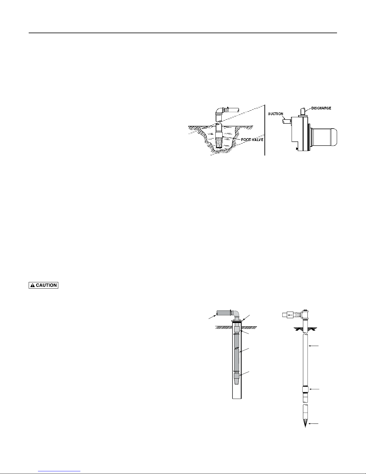
Pumping From Lakes, Streams, and Ponds (See Figure 1)
Surface Water Source
Figure 1
NOTICE: Check valve or foot valve required to maintain
pump prime.
Locate the pump as near as possible (vertically) to the
water source, to keep the suction lift (distance from
the water to the pump) as low as possible. Place the
pump on level support. Protect against excess moisture
andflooding.
Long pipe runs and many fittings increase friction and
reduce flow. Use the smallest possible number of fittings
and the shortest possible run for piping.
Support the weight of the pipe.
Be sure the water is clear of debris which can clog the
pump, such as sand, dirt, or scale. Be sure the foot valve
and the pipe are clean and in good condition; scale or
dirt in the foot valve can cause the valve to leak. Valve
leakage may cause the pump to lose its prime, which can
result in pump failure.
Ground Water Source
Well Seal
Plastic Pipe
Coupling
Plastic Pipe
Foot Valve
and Strainer
611 1293
Check valve
Steel drive pipe
Drive coupling
Dug or Cased Well
745 0993
Driven point
Driven Point
Figure 2
Page 5
Installation 5
Piping
Both the suction and discharge are tapped for 1-1/4”
pipe. If you are using hose or plastic pipe for the suction
and discharge, install 1-1/4” MNPT x Hose Barb or
1-1/4” MNPT x 1-1/4” Slip adapter(s) in the pump port(s).
When hose is used for suction, be sure it is reinforced
hose designed for this purpose.
A strainer and foot valve should be used on the end
of suction pipe, or hose, to prevent loss of prime. It
will also prevent foreign material from entering the
pump which may damage the impeller and plug the
pump. Performance ratings are for 1” pipe. Capacity
will be reduced when garden type hose or smaller
piping is used. Inspect the strainer frequently and clean
whennecessary.
NOTICE: This unit is not designed for applications
involving salt water or brine! Use with salt water or brine
will void warranty.
Pump water only with this pump.
Plastic Pipe
Plastic pipe may be used for any installation of this
pump. No special tools are required to use this pipe.
Installation can be made quickly and easily. Plastic pipe
may be used for either suction or discharge hose.
Burn Hazard. NEVER run pump dry. Running
pump without water may cause pump to overheat,
damaging seal and possibly causing burns to persons
handling pump. Fill pump with water before starting.
Burn Hazard. NEVER run pump against
closed discharge. To do so can boil water inside pump,
causing hazardous pressure in unit, risk of explosion and
possibly scalding persons handling pump.
Electrical
Hazardous voltage. Can shock, burn or
kill. Ground pump before connecting to power supply.
Disconnect power before working on pump, motor
ortank.
This pump is supplied with a dual voltage 60 Hz. motor,
factory set to 115 Volts. The pump should be plugged
into a properly grounded GFCI outlet.
Do not cut the round grounding prong off the plug.
Extension Cords
If using an extension cord, the wire gauge (wire size)
used in the extension cord must be of sufficient size to
carry the current load. This chart shows the proper cord
size for the extension cord length:
Distance Cord Wire Size (AWG)
Up to 100’ 14
100’ to 200’ 12
200’ to 300’ 10
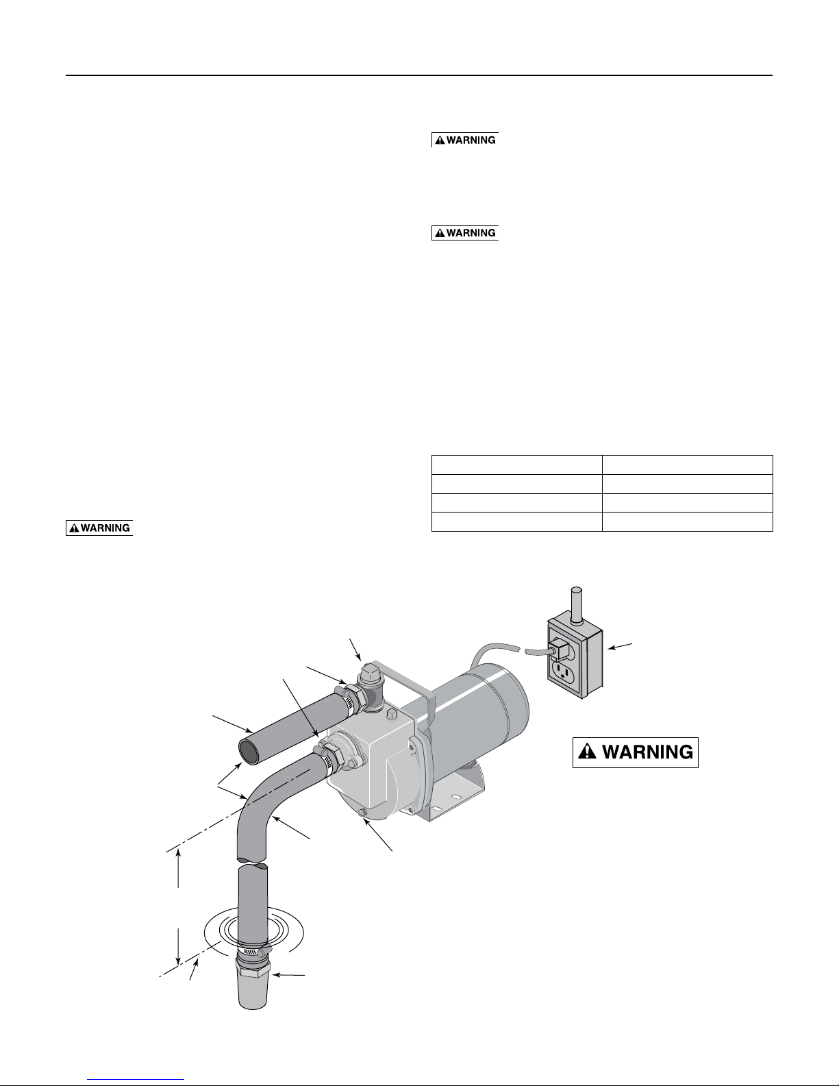
Figure 3
Discharge
Line
Plastic
Pipe
Not More
Than 20 Feet
Water
Level
Hose or plastic
pipe adapter
Optional 1-1/4" tee with
pipe plug for ease in priming
Suction
Line
Strainer and
Foot Valve
Drain
Plug
Grounded
Outlet
Box
Hazardous voltage.
Connect pump
only to a grounded,
grounding-type
three-conductor
outlet.
Do not modify
cord or plug.
Do not immerse
motor.
1173 0794
Page 6
Maintenance 6
Draining
The pump and piping should always be protected against
freezing temperatures. If there is any danger of freezing,
drain the pump and piping. To drain pump, remove the
drain plug at the bottom of the pump body and remove
priming plug. Drain all piping.
Lubrication
It is never necessary to add oil lubrication to this
centrifugal pump or its motor. The motor is of the sealed
ball bearing type, grease packed for life.
Replacing Mechanical Seal
This pump is furnished with a mechanical seal. It is
properly installed at the factory to prevent leakage, and
requires no further attention. It cannot be adjusted and
no attempt should be made to adjust it. However, it is
sometimes necessary to replace this seal. If so, please
follow the instructions carefully.
The Shaft Seal
The shaft seal consists primarily of two parts, a rotating
member and a ceramic seat.
NOTICE: The highly polished and lapped faces of the
seal are easily damaged. Read instructions and handle
the seal with care.
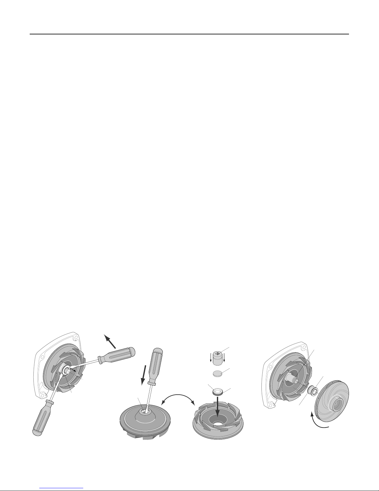
Removal Of Old Seal
1. Remove motor from pump body.
2. After unscrewing the impeller, carefully remove the
rotating part of the seal by prying up on the sealing
washer, using two screwdrivers (Figure 4A).
3. Tap out the ceramic seat with a screwdriver (see
Figure 4B). Clean cavity from which seal was
removed and clean motor shaft.
Installation Of New Seal
1. Clean polished surface of ceramic seat with a
cleancloth.
2. Wet the O-Ring in the ceramic seat with
soapsolution.
3. Press seat into cavity firmly and squarely with
finger pressure. If seat will not locate properly in
this manner, place cardboard washer over polished
face of seat and use piece of 3/4” standard pipe for
pressing purposes. Figure 4C.
4. Dispose of cardboard washer and again be sure
that polished surface of seat is free of dirt or foreign
particles, and has not been scratched or damaged by
the insertion.
5. Inspect shaft to make sure that it is clean.
6. Clean face of sealing washer with clean cloth.
7. Apply soap solution to inside diameter and outer
face of rubber drive ring.
8. Slide seal assembly onto shaft (sealing face first) until
rubber drive ring slides over shaft shoulder.
9. Screw impeller onto shaft until impeller hub hits
shaft shoulder. This will automatically locate seal in
place and move the sealing washer face up against
floating seal face. Figure 4D.
10. Reassemble pump in reverse order of disassembly.
Mechanical seal
Mechanical seal
rotating half
A-Seal removal-rotating half B-Seal removal-ceramic seat C-Ceramic seat installation D-Rotating half installation
ceramic seat
Seal Plate
Figure 4
3/4" socket
or pipe
Cardboard
washer
Polished
surface
o
n
v
r
e
u
r
T
(supplied w/seal)
Rubber
surface
Sealing
face
Shaft
shoulder
Rubber drive
ring
Impeller
567 0395
Page 7
Troubleshooting 7
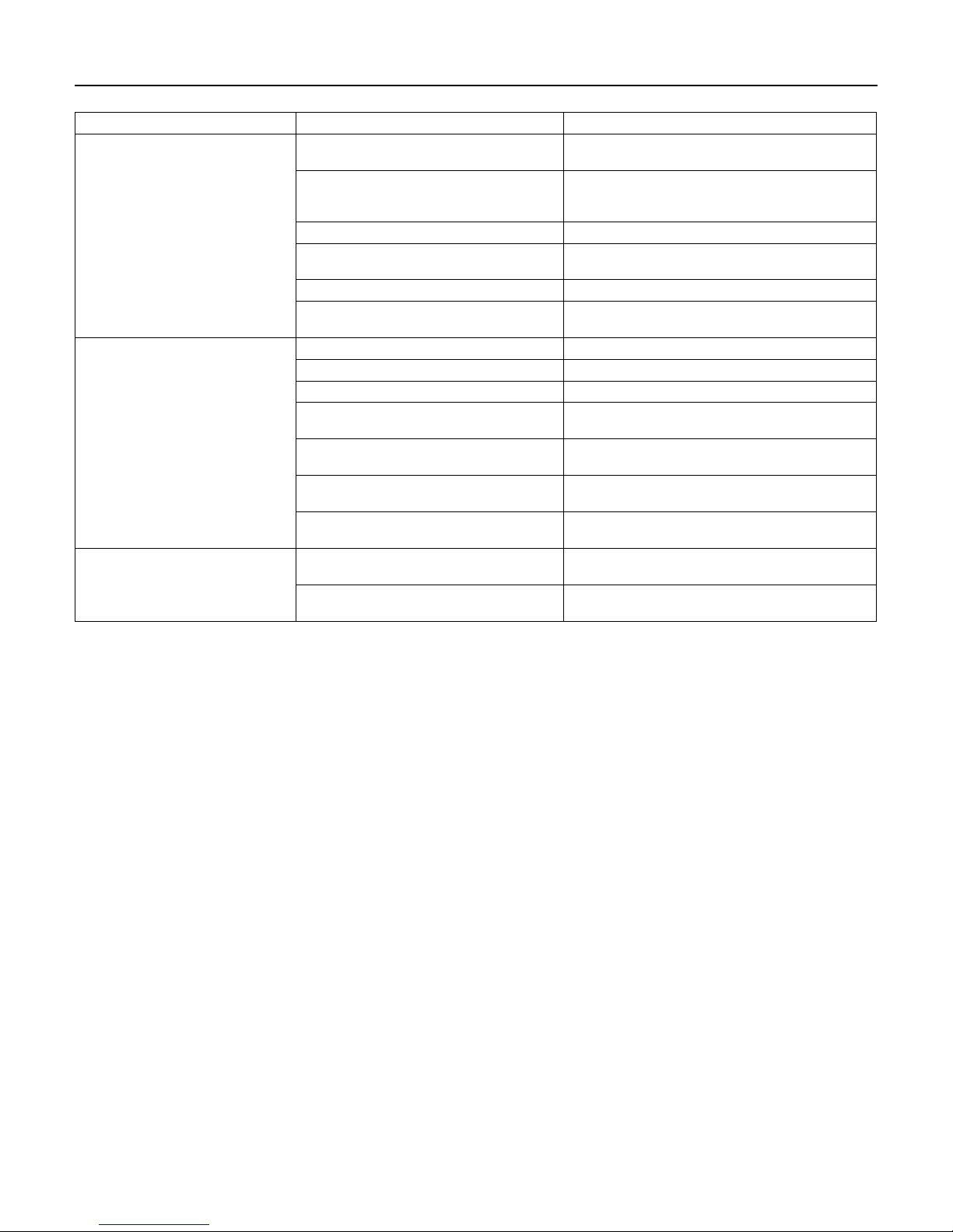
Symptom Probable Cause(s) Corrective Action
Make sure pump body is full of water. See priming
instructions.
Check voltage at motor terminals and at meter when pump is
operating. If low, refer to wiring instructions, or check with
your Power Company. Check for loose connections.
Locate pump closer to source of water. Make sure suction
piping is large enough.
Check water supply. Add pipe to suction to keep it
submerged.
Add lengths of suction pipe to keep it well below the water
surface.
If caused by suction pipe friction, enlarge piping and foot
valve. Otherwise move pump closer to water level.
A larger pump is needed.
Order replacement parts, using repair parts list in this
manual.
See that all piping is supported to relieve strain on pump
assembly.
Check the voltage dial on the motor to set it to the correct
input voltage.
Failure to pump.
Reduced capacity and/or head (pressure).
Mechanical troubles and noise.
Pump not properly primed.
Speed too low.
Total head too high. A pump designed for high head service is needed.
Suction lift too great.
Excessive air leak in suction line. Check and repair suction line.
Water level drops while pumping, uncovering
suction inlet.
Air pocket or leaks in suction line. Check suction piping.
Clogged impeller. Remove and clean.
Foot valve strainer too small, or clogged. Use larger foot valve, clean.
Insufficient submergence of suction pipe.
Excessive dynamic suction lift (over 20 ft.).
Total head (pressure) more than that for which
pump was intended.
Excessively worn impeller.
Suction and/or discharge piping not properly
supported and anchored.
Motor runs hot and overload kicks off.
Page 8
Repair Parts 8
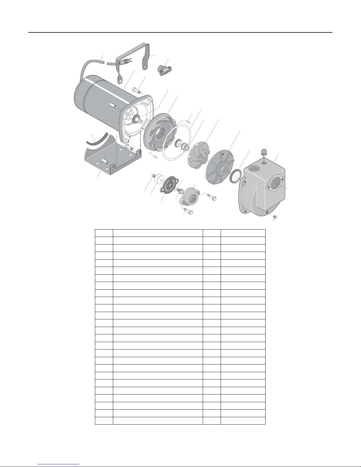
22
21
25
23
24
1
2
3
4
6
20
19
16
18
15
17
5
14
8
7
9
12
10
11
13
Ref. Part Description Qty. Part Number
1 Motor - 1/2 HP 115V/230V - 60 Hz. 1 J218-582A-115-PKG
2 Hex Capscrew - 3/8 - 16x1-1/2” 4 †
3 Water Slinger 1 17351-0009
4 Seal Plate Diffuser 1 C3-120
5 Roll Pin 3/32 x 5/16” 2 U30-522SS
6 Gasket 1 N20-35
7 Shaft Seal 1 U109-6A
8 Impeller 1 C5-184P
9 Diffuser Cover 1 C6-47P
10 Diffuser Ring 1 C21-11
11 Pump Body 1 C76-41
12 Pipe Plug - 1/2” Square Head 1 U78-59ZPS
13 Pipe Plug - 1/4” Hex Head 1 U78-941ZPV
14 Flange - 1-1/4” NPT 1 PW16-4
15 Capscrew - 3/8-16 x 1” Hex Head 2 U30-74ZP
16 Check Valve Flapper 1 PW22-1
17 Washer 1 U43-41SS
18 Capscrew - 1/4-20 x 3/4” Hex Washer Head 1 37006-4652
19 Washer 2 U43-138ZP
20 Hex Nut - 1/4-20 1 U36-36ZP
21 Base 1 J4-9
22 Rubber Pad 1 C35-5
23 Handle 1 C54-21
24 Strain Relief 1 U71-7
25 Cord 1 U17-402
† Standard hardware item; purchase locally.
 Loading...