

Page 1
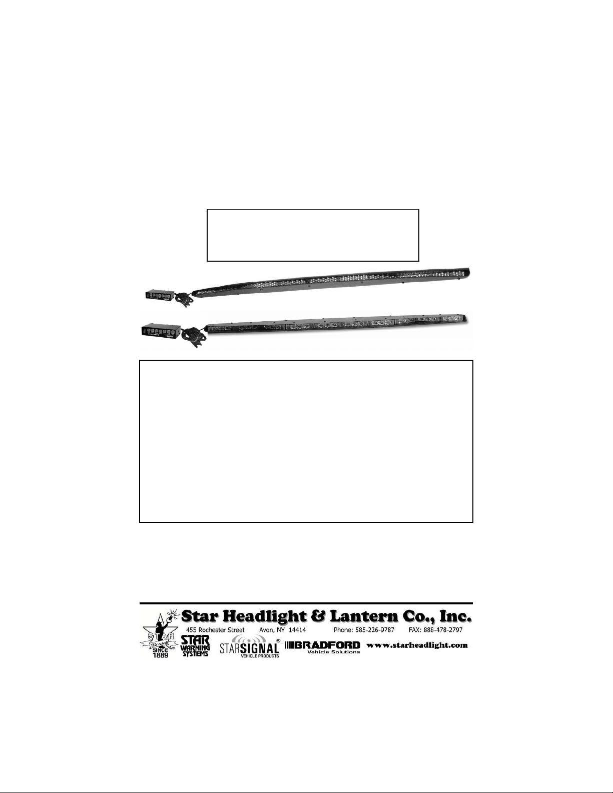
Star Phantom
Star Phantom
®
Rear Window Undercover Interior
LED Traffic Director
Models
ULB42-TD ULB44-TD
(Discrete LEDs) (Gen 4 Starburst LEDs)
The manufacturer warrants this LED light against factory defects in mater ial and workmanship for five years
after the date of purchase. The owner will be responsible for returning to the Service Center any defective
item(s) with the transportation costs prepaid. The manufacturer will, without charge, repair or replace at its
option, products, or part(s), which its inspection determines to be defective. Repaired or replacement
item(s) will be returned to the purchaser with transportation costs prepaid from the service point. A copy of
the purchaser's receipt must be returned with the defective item(s) in order to qualify for the warranty
coverage. Exclusions from this warranty include, but are not limited to, domes, and/or the finish. This
warranty shall not apply to any light, which has been altered, such that in the manufacturer's judgment, the
performance or reliability has been affected, or if any damage has resulted from abnormal use or service.
There are no warranties expressed or implied (including any warranty of merchantability or fitness), which
extend this warranty period. The loss of use of the product, loss of time, inconvenience, commercial loss or
consequential damages, including costs of any labor, are not covered . The manufacturer reserves the right
to change the design of the product without assuming any obligation to modify any product previously
manufactured.
This warranty gives you specific l egal rights. You might also have additional rights that may vary from state to
state. Some states do not allow limitations on how long an implied warranty lasts. Some states do not allow
the exclusion or l imitation of incidental or consequential damages. Therefore, the above limitation(s) or
exclusion(s) may not apply to you.
If you have any questions concerning this or any other product, please contact our
If a product must be returned for any reason, please contact our
Customer Service Department to obtain a Returned Materials Authorization
Please write the RMA # clearly on the package near the mailing label.
LED FIVE YEAR LIMITED WARRANTY
Customer Service Department at (585) 226-9787.
number (RMA #) before you ship the product back.
PLITSTR344 REV. E 5/20/14
Page 2

Mounting
IMPORTANT: Please read all of the following instructions before installing your new warning light.
The
Star Phantom
®
line of lights is designed to be
mounted on the inside of your vehicle. They are not intended for
exterior applications and are not warranted against water damage.
It is the sole responsibility of the owner to ensure the warning light is
secure. Check your light every time you enter the vehicle to ensure that
it is mounted securely. The manufacturer assumes no responsibility for
the secure mounting of this light.
The following mounting instructions describe the standard, most common way to
mount this light. This method may or may not apply to your vehicle. Because
vehicles can vary widely in their design, it may be necessary to configure the brackets
differently than described. Some applications may require you to design your own
custom brackets. The installer assumes all responsibility for the integrity of the
installation. It is the sole responsibility of the owner to ensure the light is secure.
P30073-4
(QTY=12)
#8 FLAT WASHERS
P30150-220P
P30054-27
(QTY=2)
#10-32 x 1/2" CARRI AGE BOLT
P30076-8
(QTY=2)
1/4" FLAT WASHER
(USE AS SPACER)
(QTY=2)
ATTACHING BRACKET
P30150-97P
(QTY=2)
DOUBLE SLOTTED "L" BRACKET
P30073-3
(QTY=2)
#8 TOOTH WASHER
P30093-5
(QTY=2)
#8 NUT
P30150-79P
FORKED "L" BRACKE T (Style 1)
P30150-189P
FORKED "L" BRACKE T (Style 2)
P30073-4
#8 FLAT WASHER
P30053-24
3
#8 x
" SELF-TAPPING P HILIPS HEAD SCREW
8
(QTY=2)
P30053-29
3
#8-32 x
" PHILIPS HEAD SCR EW
8
(QTY=6)
P30053-24
3
#8 x
" SELF-TAPPING PHILIPS HEAD SCREWS
8
P30073-4
#8 FLAT WASHERS
P30150-97-2P
SLOTTED STRIAGH T BRACKET
(QTY=2)
-1-
(QTY=2)
(QTY=2)
P30094-10
(QTY=2)
#10-32 SERRATED FLANGE NUT
Page 3
Mounting (CONT'D)
Before beginning the installation:
• Determine where the Traffic Director is to be mounted.
• Ensure there are no obstructions hindering the visibility of your traffic director.
• Select a location to mount your controller that is dry, out of direct sunlight, and free of
dirt and dust. Under the vehicle's instrument panel is usually the best choice.
• Determine the path your cable, which connects the controller to the Traffic Director,
will take. The cable should exit the left side of the Traffic Director when you are
facing both the lightbar and the controller.
Be sure the cable attached to your Traffic Director is long enough for proper installation.
If it is too short, you will need to order a Traffic Director with the correct length cable pre-
installed. The standard length for the cables is 15'. Star does not recommend
“splicing in” additional cable when the supplied cable is too short. Traffic Directors
with 30', 45' and 60' cables are available upon request.
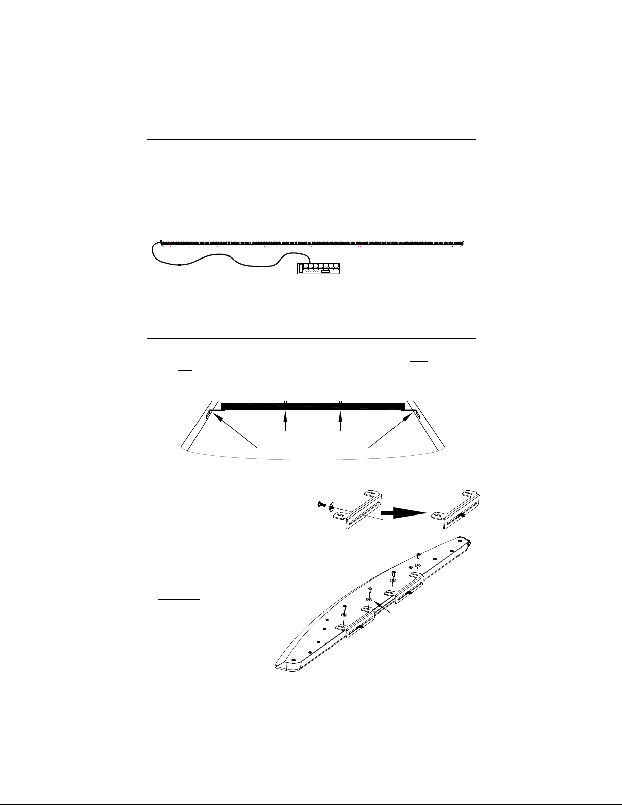
This light is designed to be mounted in the rear window of a vehicle using both the forked
brackets and the corner post brackets. Failure to use both brackets could result in a
faulty mount and will void the warranty. If your vehicle is not compatible with these
brackets you must custom design mounting brackets
.
Forked Brackets
Corner Post Brackets
FORKED BRACKET INSTALLATION
1. Insert a carriage bolt through one of the
1/4” washers and slide it through the back
of each of the long L-brackets. Please
note that washer is used as a spacer on
the square neck of the carriage bolt.
2. Remove the four of the #8 Phillips head screws shown to the
right from the light and add the # 8 washers. Use them to
install the long L-brackets.
CAUTION: Take extreme caution not to over
tighten the screws!!!
-2-
P30073-4 (QTY=4)
#8 FLAT WASHERS
Page 4

Forked Bracket Installation (CONT'D)
3. Attach a forked bracket to each L-bracket
using one of the nuts.
Note: There are two different style forked
brackets included. Use the one that suits
your application best.
Leave the nut slightly loose to
allow for minor adjustments during
the remainder of the installation.
4. Determine an appropriate user-supplied screw to penetrate the
headliner and securely mount the bracket to the roof brace (or other
mounting location) through the mounting hole in each forked bracket.
CAUTION: Take care to ensure when selecting a screw and drilling the hole that it
Mounting
Hole
is capable of supporting the weight of the light and that it does not penetrate the
roof of the vehicle.
Press light tightly
against window
5. Using the slots in the brackets, adjust the
light so that it fits tightly against the window,
carefully bending the forked brackets, if
necessary, and tighten the screws.
Tighten the nuts securing
the mounting brackets
CAUTION: Take extreme caution not to over tighten the screws!!! Over tightening
of the screws can strip the holes.
CORNER POST BRACKET INSTALLATION
1. Connect one of the double-slotted "L" brackets to each of the
slotted straight brackets using one of the screws, a flat washer,
a tooth washer, and a nut.
2.
Connect one bracket to each end of your
Star Phantom
®
using the
screws provided. Loosen both screws slightly to allow for adjustability
when installing the lightbar.
-3-
Page 5

Corner Post Bracket Installation (CONT'D)
3. Adjust the mounting brackets so that they rest flat against the corner post on each side
of the vehicle., then tighten all the screws.
4. Mark the two spots where you will be attaching your screws to the corner post and drill a
1/8" hole in each of the marked locations.
Caution: Be sure to check that there are no airbags, wires, or anything else behind the
molding that may be damaged by the screw holes.
5. Use two of the self-tapping screws in each side to secure each bracket to the corner
posts.
6. Once the brackets are securely tightened, check your mount to ensure the desired angle
is achieved. Stand behind the vehicle and inspect the light through the rear window.
Make any final adjustments necessary.
CAUTION: Take extreme caution not to over tighten the screws!!! Over tightening of
the screws can strip the holes and result in a faulty mount.
Because of the wide variety of mounting applications, Star Headlight
& Lantern Co., Inc. assumes no responsibility for the secure mounting
of this light. It is the responsibility of the installer and/or owner to
ensure the lightbar is mounted securely. Check your light every time
you enter the vehicle to ensure that it is mounted securely.
-4-
Page 6

Electrical Connections
1. The cable attached to your Traffic Director should have a green connector (part #CPSS-
153) attached to it. Eight colored 18 AWG wires, one bare drain wire, and a large red
12AWG wire should already be connected from the cable to the connector.
2. Connect a ground wire to the interior empty terminal on the green connector. (See
diagram above) The corresponding terminal plugs into the outlet on the back of the
controller and is marked BAT-.
3. Supply power for the unit from a fused, +12 VDC source capable of delivering at least 15
amps of current (use a 20 amp fuse). Star recommends the use of an ignition switched
supply to avoid the possibility of draining the vehicle's battery should the unit be
accidentally left on.
4. Connect your power supply to the terminal on the green connector that corresponds to
the outlet on the back of the controller marked BAT+.
5. The lamp brightness will be somewhat diminished if a large voltage drop exists between
the vehicle's battery and the controller. If voltage drop is a problem, use a relay to
control a direct battery feed. A generic relay designed for automotive lamp service
should be available from most automotive stores for this purpose. If using a relay, don't
forget to fuse the feed and signal wires at their source, with appropriate values.
6. Your Traffic Director should now be ready to operate.
It is imperative that you supply a ground wire to the terminal marked
"BAT -" on the controller. You must not let the controller's case
supply ground. Use 12 AWG wire for all power and ground
connections
-5-
Page 7

(Wiring CONT’D)
Wiring for Optional Automatic Activation
1. The Traffic Director may also be wired to automatically bypass the ULB42-TD--2 controller On/
Off switch and turn on through the use of an alternate power source (i.e. lightbar switch, siren
switch, reverse switch, etc.).
2. When you apply +12VDC
to the 12AWG wire
supplying the stick with
power, you will bypass the
On/Off switch and activate
the Traffic Director. When
activated, the Traffic
Director will automatically
enter the "Warn" pattern.
Operation
Important: This product is used to direct traffic. Improper use may
result in vehicular collision, personal injury and/or death. Star
Headlight & Lantern Co., Inc., and its subsidiaries shall not be held
responsible for damages directly or indirectly caused by improper
use of this product. Always carefully consider the effect on traffic
that the selected light pattern will have before engaging the lights.
1. Operation of your Traffic Director is straightforward. The controls include an On/Off
switch, four Pattern Select buttons, and three additional "option" buttons.
ULB42-TD-2 Controller
2. When the On/Off switch is activated, the traffic director will automatically go into the
WARN pattern. The LED display should show the "WARN” pattern and the WARN label
should glow red.
3. Select the desired pattern (if different from
the current pattern) by using any of the
Pattern Select buttons. The Pattern Select
buttons include Left, Center, Right, and
Warn. The selected pattern label should
change to red and the roof display should
mimic exactly the display on the controller.
-6-
Page 8

Operation (CONT'D)
4. The ULB42-TD-2 controller also has three "option" buttons: Fast, Dim, and Alt.
Fast
This button allows the user the option to display any of the patterns in a "faster" mode.
This button will also change the two end lights to flash in a fast random pattern (if they
have been enabled by the Alt button). Pressing the "Fast" button once should change
the "Fast" label to red and speed up the pattern. Pressing the button again will change
the "Fast" label back to green and revert the pattern to the standard speed.
Dim
When the "Dim" button is pressed the "Dim" label
will change to red and the Traffic Director will dim
slightly (Night Mode). Pressing it again will return
the Traffic Director to full brightness.
Alt
The two arrays on each end are not part of the “traffic
directing” patterns. The "Alt" button will enable and
disable the end flashing LED arrays.
Only the center 6 arrays will be utilized during the Left, Center Out, and Right patter ns.
The last two segments on each end will alternate ba ck and forth producing an In -Out warning pattern.
5. When using the Traffic Director, always be sure that the pattern selected is appropriate
for the present hazard condition. The potential danger in displaying an inappropriate
pattern cannot be overstated.
6. To avoid possible damage, the controller should be turned off prior to engine starting. It
is possible, though not likely, to confuse the controller if the vehicle's battery is low and
the engine is started with the controller running. If you notice that the controller's display
shows something out of the ordinary, simply push the power switch to the off position
and back on again. This should clear any fault caused by improper voltage being
supplied to the unit.
Once your Traffic Director is installed, please test all the patterns, options, and alternate
versions to familiarize yourself with the various patterns and the operation of the controller.
Troubleshooting
The ULB42-TD and ULB44-TD contain no user serviceable parts. The ULB42-TD-2
controller contains two ATO "blade-type" fuses located in the back of the controller. The
fuses are accessible from the rear of the controller. The 20 amp fuse controls power to the
bar light assembly, while the 2 amp fuse powers the controller. If the 20 amp fuse blows the
controller will continue to function normally, however, the lightstick will not. It is important to
note that under normal circumstances the only reason a fuse will blow is because there is a
fault in the system. If a fuse blows repeatedly it is a signal that something is wrong.
Do not replace a blown fuse with anything other than the same amperage rating as marked
on the rear panel of the controller; doing so may damage the unit, or worse yet start a fire.
Likely causes of blown fuses are improper wiring or harness damage.
-7-
 Loading...