

Page 1
INSTALLATION AND INSTRUCTION MANUAL
DLX3-RRK / DLX4-RRK / DLX6-RRK
LED Undercover Roof Rack Lighting Kit
The manufacturer warrants this LED light against factory defects in material and workmanship for five years
LED FIVE YEAR LIMITED WARRANTY
after the date of purchase. The owner will be responsible for returning to the Service Center any defective
item(s) with the transportation costs prepaid. The manufacturer will , without charge, repair or replace at its
option, products, or part(s), which its inspection determines to be defective. Repaired or replacement
item(s) will be returne d to the purchaser with transportation costs prepa id from the service point. A copy of
the purchaser's receipt must be returned with the defective item(s) in order to qualify for the warranty
coverage. Exclusions from this warranty include, but are not limited to, domes, and/or the finish. This
warranty shall not apply to any light, which has been altered, such that in the manufacturer's judgment, the
performance or reliability has been affected, or if any damage has resulted from abnormal use or service.
There are no warranties expressed or implied (including any warranty of merchantability or fitness), which
extend this warranty period. The loss of use of the product, loss of time, inconvenience, commercial loss or
consequential damages, including costs of any labor, are not covered. The manufacturer reserves the right
to change the design of the product without assuming any obligation to modify any product previously
manufactured.
This warranty gives you specific l egal rights. You might also have additional rights that may vary from state to
state. Some states do not all ow limitations on how long an implied warranty l asts. Some states do not allow
the exclusion or l imitation of incidental or consequential damages. Therefore, the above limitation(s) or
exclusion(s) may not apply to you.
PLIT478 REV. - 8/27/12
Page 2
Due to continuous product improvements, we must reserve the right to change any specifications and
information, contained in this manual at any time without notice. Star Headlight & Lantern Co., Inc. makes no
warranty of any kind with regard to this manual, including, but not limited to, the implied warranties of
merchantability and fitness for a particular purpose. Star Headlight & Lantern Co., Inc. shall not be liable for
errors contained herein or for incidental or consequential da mages in connection with the furnishing,
performance, or use of this manual.
Installation Notes
Proper installation of the unit is essential for years of safe, reliable operation. Please read
all instructions before installing the unit. Failure to follow these instructions can cause
serious damage to the unit or vehicle and may void warranties.
• The installer must have a firm knowledge of basic electricity, vehicle electrical systems,
and emergency equipment.
• If you need to drill any holes when installing this light, please take care to check that
BOTH SIDES of your drilling surface are clear from obstructions, to ensure that you do
not damage your vehicle and or pre-existing wiring.
• Choose a mounting location away from any air bag deployment areas.
• Controls should be placed within convenient reach of the driver.
• Use only soap and water when cleaning this product. Use of other chemicals may
discolor the lens and/or housing, thus diminishing the output of the light. Lenses that
have become discolored should be replaced immediately!
• DO NOT use a pressure washer to clean this light. Use of a pressure washer may
damage the light and WILL VOID THE WARRANTY.
Before beginning the installation:
- Determine where the light is to be mounted.
- Check to see that there are no obstructions hindering the visibility of your light from the front,
rear, or side of the vehicle (wherever applicable).
- Determine where you will mount the switch.
- Verify that you have a clear path between the light and switch for your wires to run.
NOTICE
Please Note: These instructions are provided as a general guideline only. Some
vehicles may require special mounting, wiring, and/or weather-sealing. This is the
sole responsibility of the installer. Star Headlight & Lantern Co., Inc. assumes no
responsibility for the integrity of the installation for this or any of its products.
It is the sole responsibility of the installer to ensure the warning
light is secure. The manufacturer assumes no responsibility for
the secure mounting of this light.
-1-
Page 3
Mounting
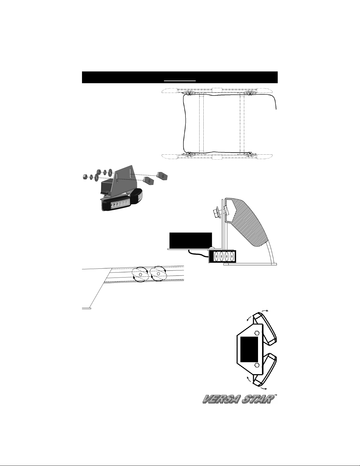
1. Determine how you wish to mount the
lights on the roof rack paying
particular attention to where you want
to run the harness to the switch (not
included).
2. Each undercover head should come
with two T-Bolts that will be used to
attach it to the roof rack.
4. Mount one of the brackets to the
rail of the roof rack by slightly
angling the T-bolts allowing them
to slip into the slot on the rail.
3. Install one T-bolt through each slot in the Lbracket as shown to the left. Loosely secure
the T-bolt with a flat washer, lock washer, and
a nut on each bolt. Repeat this for all of the
light heads.
5. Loosely hand tighten the nuts while slightly rotating each T-bolt
clockwise until it contacts the top and bottom of the groove,
helping secure it inside the groove. You may wish to use a
screwdriver or similar tool to help you rotate the T-bolts.
6. After all of the heads have been installed, make your final
adjustments positioning each head side-to-side and up and down
where you want them. Tighten all of the nuts, ensuring the T-bolts
remain rotated against the top and bottom of the roof rack channel.
7. The angle of each individual light can be adjusted by loosening the
bolt securing it. Make your adjustments then tighten the bolt.
-2-
Page 4

External Wiring Connections
When wiring your lights, it is recommended that you take the following
• Keep LED modules and any radios as far away from each other as possible.
• Separate the radio wires and the LED wires:
precautions to reduce any Electromagnetic Interference (EMI).
• Any excess wires should be cut short.
For ease of installation, there are only two wires in the main harness of the DLX*-RRK. If
the default flash pattern and synchronization settings are acceptable, these are the
only wires you need to connect.
Black: (Ground) – Connect the black wire to the negative side of your battery.
Red: (Power) – Connect the red wire to your switch supplying power.
+10-16VDC (DLX3 heads) +10-30VDC.(DLX4/DLX6 heads)
Optional Programming
This lighting kit is designed such that there are several additional
options you can program including:
If you wish to change any of these, you will need to gain access to
the terminal block located behind each head.
To do this, remove the two screws that secure the plastic terminal
block cover (see diagram to right).
• Single or Split Flashing
• Flash Pattern
• Synchronization
Single or Split Flashing
(DLX4 and DLX6 Only)
By default, the lights in the DLX4-RRK and
DLX6-RRK assemblies are wired for “Single”
mode (the whole head flashes at once).
Optionally you can wire them for “Split
Mode” (the pattern alternates back and forth
Green/White: (Split/Single Mode) – The Green/White wire controls whether your light
Single Mode: Connect with Black to Ground — Split Mode: Connect with Red to Power
Green: (Split Mode Steady Side Swap) – If you are in Split mode and select the Steady
flashes in Single Mode or Split Mode. It is defaulted for Single Mode.
between the two halves of each light).
pattern, only one side will be steady while the other will flash. If you want to swap
the Steady side to the other half of the light, hold the green wire to ground for 15
seconds until the light flashes 5 times, then release it.
-3-
Page 5

(Optional Programming cont’d)
Pattern Programming
The capped off green
wires are used to
program the desired flash
pattern.
There are 10 different
Pattern Types you can
cycle through in two
different Phases, and an
additional “Steady Burn
Mode”.
If you have a DLX4 or DLX6 and are running in "Split Mode", the two halves will alternate
the pattern back and forth.
To change the pattern:
• Touch the green wire to ground for approximately 1 second and release it to cycle
through Patterns 1-20. After Pattern 20, the light will cycle back to Pattern 1.
PLEASE NOTE: The pattern cycle does NOT include the Steady Burn mode.
To access the Steady Burn pattern, use the programming Shortcut.
Phase 1
Phase 2
Flash
Pattern
Pattern
Type
Quadflash †
Quadflash w/Post-Pop †
Singleflash †
Doubleflash †
Pattern Description
Flash
Pattern
1 11 K Flicker †
2 12 L Fast Doubleflash
3 13 M Tripleflash †
4 14 N PSU Flicker
5 15 O PSU Random
6 16 F
7 17 G
8 18 H
9 19 I
10 20 J Variable AKA Delta-Omega
NA Steady
† - Approved patterns for SAE J845 and California Title 13
Pattern Shortcuts: Hold Green wire to ground for indicated time.
Split Mode Phases: One side flashes in Phase 1, the other
side flashes in Phase 2
Steady Burn: Not in pattern cycle. Only accessible through
shortcut. Hold Green wire to ground for 18
seconds (light will flash 6 times).
Shortcut
Pattern 1
(Phase 1)
3 sec or 1 flash
Pattern 11
(Phase 2)
9 sec or 3 flashes
Pattern 6
(Phase 1)
6 Sec or 2 flash
Pattern 16
(Phase 2)
12 sec or 3 flashes
18Sec
:
:
:
:
-4-
Page 6

(Optional Programming cont’d)
Synchronization
This harness has been pre-programmed at the factory so
that when properly mounted with the first pair of lights in the
rear of the vehicle, the next two pairs of lights at the front,
and the last pair of lights towards the rear, the four lights on
the right side of the vehicle are synchronized together and
the four lights on the left side of the vehicle are
synchronized together (see diagram to right).
We recommend using the factory default synchronization
settings. But if you wish to change the synchronization, please
review the section below and keep in mind the following:
• Only 6 lights can be synchronized. You cannot
synchronize all 8 lights.
• ALL SYNCHRONIZED LIGHTS MUST HAVE THE
SAME PATTERN TYPE !!!
• Lights that are programmed for the STEADY BURN
pattern will NOT be synchronized with any other lights.
• For lights running in Single Mode, Patterns 1-10 are in
Phase 1 and Patterns 11-20 are in Phase two.
• For lights running in Split Mode (DLX4/DLX6 only), Patterns 1-10 will flash side 1 in
Phase 1 and side 2 in Phase 2. Patterns 11-20 will flash side 1 in Phase 2, and side 2
in Phase 1.
• Lights or sides set for the SAME phase flash together (simultaneous), lights with
DIFFERENT phases flash opposite one another (alternate).
• Use the Pattern Shortcuts listed on page 4 to simplify programming.
1. If you wish to change the synchronization pattern that the lights come pre-programmed
with, remove the plastic terminal block cover as described on page 3.
2. Disconnect the white wires on
each light you will be
programming.
3. For the DLX4 and DLX6, verify
that the Green/White wire from
each light is connected correctly
so your heads are in the desired
mode (Single or Split mode), as
described on page 3.
4. Program the pattern for the first light as described on pages 4.
5. Program the second light with the same Pattern Type, selecting the Phase based upon
the desired output (alternating or simultaneous).
6. Once you have found the desired pattern on the second light, re-cap the green wire to
prevent it from coming into contact with ground again.
7. Repeat Steps 1-6 above for each additional head you wish to synchronize.
8. Reconnect the white wires in the terminal block of the synchronized lights.
9. Replace the terminal block covers.
-5-
Page 7

Troubleshooting Guide
These lights use state-of-the-art Light Emitting Diode (LED) technology. This light is
comprised of ultra-bright LEDs that are operated in a multiplexed mode to efficiently
produce light output with lifetimes up to 100,000 hours. Under normal circumstances, you
will not need to replace any LEDs in this light. If any of the LEDs in your light do fail,
please contact Star Headlight for arrangements to have them repaired.
NOTE:
Symptom Possible Cause
No Light
LED's appear dim
Erratic operation
Most failures can be traced to wiring and battery
problems. Check "quick-connects” and wiring to insure
that correct voltage/polarity is reaching the light.
Power or polarity
Inline fuse blown
Bad ground
White wire shorted
Green wire shorted
Shorts
Wiring
Low battery voltage
Power wires are too
small/long
Bad routing of wires
Check
A nominal +10-16VDC (DLX3) or 10-30VDC (DLX4 and DLX6)
should be reaching the red wire
Is power hooked up backwards?
Positive ground vehicle? (Unit designed for negative ground
vehicles)
Is an external fuse or circuit breaker used?
Are the negative leads connected to a good ground?
White wire should only be connected to other white wires.
Power applied to it will prevent the light from flashing
Green wire should remain unconnected.
If grounded, light will cease to function.
Do wires run thru bare metal holes that have damaged them?
Are the wires pinched or broken anywhere?
Measure while lights are on. Voltage below 10V will result in
Measure while lights are on. Voltage below 10V will result in
Do wires run thru bare metal holes that have damaged them?
Are the power or control wires close to:
Strobe power supplies, tubes, cables, police/two-way radios or
Try running with the car and all other accessories off
reduced LED output.
reduced LED output.
alternator?
If you have any questions concerning this or any other product, please contact our
Customer Service Department to obtain a Returned Material Authorization
Please write the RMA # clearly on the package near the mailing label.
Customer Service Department at (585) 226-9787.
If a product must be returned for any reason, please contact our
number (RMA #) before you ship the product back.
-6-
Page 8

-7-
 Loading...