

Page 1
&
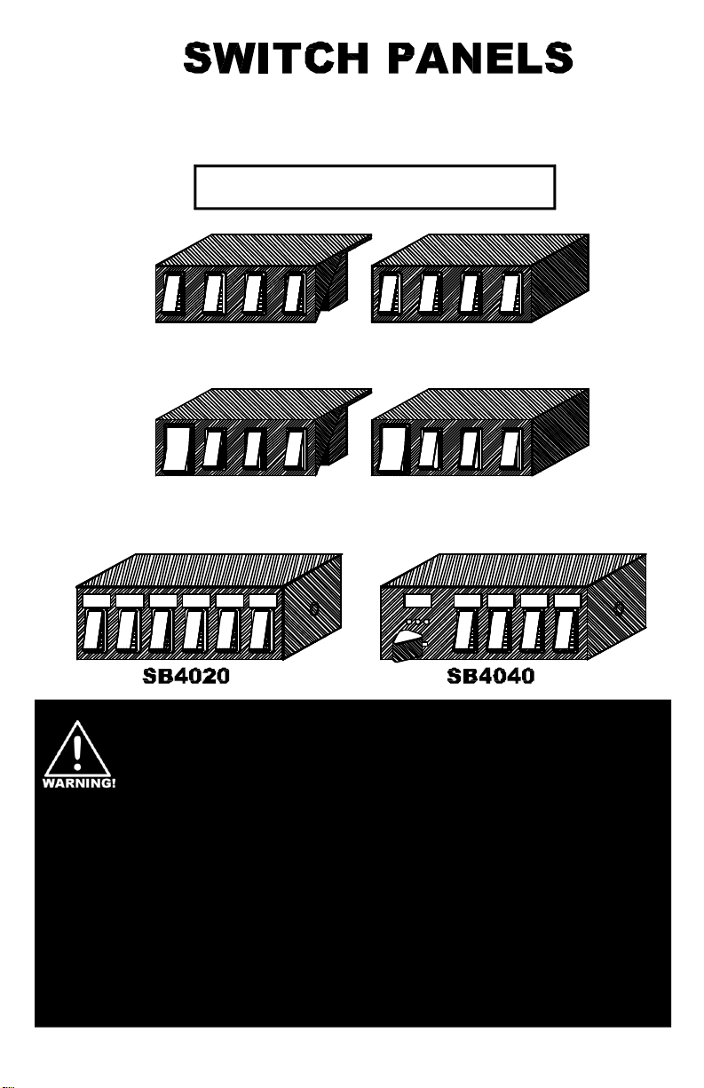
SWITCH BOXES
INSTALLATION GUIDE
ROTATORS STROBES
LEFT
ALLEY
SP1515
SP3015
WORK
RIGHT
ALLEY
LIGHTS
FLASHERS
SB1515
SB3015
GRILL
MODE
LIGHTS
1 2 3
HEADLIGHT
FLASHER
CORNER
LIGHTS
TAKE
DOWN
IMPORTANT: Please read all of the following instructions before installing
Installers should keep in mind the importance of safe installation to protect the lives of those
your new switchbox.
who may depend upon this equipment. Please especially note the following important safety
• To properly install this equipment you must have a good understanding of automotive electrical
instructions:
procedures and systems, along with proficiency in the installation and use of safety warning
equipment.
• Position the switch module so the vehicle controls can be operated safely under all driving conditions.
Route your wires such that they do not interfere with the vision of the driver or the operation of the
steering wheel, gear shifter, and/or airbag.
• When drilling into a vehicle, be sure both sides of the hole are clear of anything which may be
accidentally damaged.
• Keep these instructions in a safe place for future reference when performing maintenance.
WARNING : Failure to follow all safety precautions may result in serious injury or property
damage.
PLITSTR219 REV. E 12/4/07
Page 2

1. Select a location to mount your switches. Pos ition the switch module so the vehicle controls can be
operated safely under all driving conditions.
2. The SB1515, SB3015, SP1515, and SP3015 can all be mounted
Installation
using the two holes in the top. For the “SB” models you will need
to remove the bottom cover to gain access to the holes.
• Using your own screws (or other fasteners) mount the
switches through the two holes in the housing.
• Take extreme caution so that you do not damage any of the
wires attached to the switches.
• You may have to gently bend the wires in order to gain clear
access to each mounting hole.
3. The SB4020 and SB4040 can all be mounted using the enclosed “U” bracket ,
or in any appropriate console, using the enclosed bolts.
4. For the SB1515, SP1515, and SP1515-MOM: All four switched circuits are
protected by 15 amp automotive blade type fuses.
5. For the SB3015 and SP3015: Switch 1 is protected by a 30 amp
SB4020
SB4040
automotive blade type fuse, and switches 2-4 are protected by 15 amp
automotive blade type fuses.
6. For the SB4020: A thermal lockout type circuit breaker, rated at 40 amps, protects circuit #1.
Circuits #2-#6 are protected by 20 amp automotive blade type fuses.
7. For the SB4040 : The circuit on Position 1 of the slide switch is protected by a 20 amp automotive
blade type fuse. A thermal lockout type circuit breaker, rated at 40 amps, protects Position 2 and
Position 3. The four circuits connected to the rocker switches are protected by 20 amp automotive
blade type fuses.
8. Use wire with a gauge equivalent to the wire extending from your switch module to connect each lead
to its corresponding accessory. Use the diagram on the following page and the table on the back of
this booklet to properly identify which lead goes to which switch. For the SB4020, SB3015, and
SP3015, switch 1 should be used to control any high current loads (i.e. – lightbar). For the SB4040,
Positions 2 and 3 of the slide switch should be used for high current loads.
9. You may use 18 AWG wire to connect the black ground lead to a good chassis ground. Each device
connected to the switch must be grounded with its own separate ground wire. Refer to your installation
instructions included with each device to determine proper wire gauge and grounding methodology .
10. For the SB4020 and SB4040: Use 18 AWG wire to connect the 18 AWG red lead to the accessory
terminal of the ignition switch or the vehicle instrument light circuit. This will control the backlighting on
your switch panel.
11. Power for the switch module (or for each switch) may be obtained from a vehicle power distribution
center or by a 60, 80, or 100 amp master circuit breaker. We recommend that all circuits be protected
with fuses or circuit breakers. We suggest the good electrical practice of fusing all circuits connected
to the battery at the battery. Connect each red wire from your switch module to your power source.
Be sure to use wire that is AT LEAST the equivalent gauge of each red wire you are connecting to the
master circuit breaker or a power distribution center. Proper wire gauges can be found in the diagram
on the next page. If power is obtained in the engine compartment, and a hole is drilled in the firewall,
be sure to use a grommet in the hole as to prevent the edges from damaging the wire and causing a
short.
CAUTION: Take care to insure that both sides of the drilling surface are free and clear of any parts
which may be damaged, such as brake lines, fuel lines, electrical wires, or any other vital
12. For the SP1515-MOM: Switch 4 is a momentary switch. Pressing (and holding) the top of the switch
will activate the device attached to it. Pressing the bottom of the switch will have no effect.
13. For the SB4040: The slide switch on this model is set for progressive mode by default. The OFF
parts of the vehicle.
position is found by moving the switch all the way to the left (Position 0). When moved to Position 1,
the components connected to the blue wire are activated. When the switch is slid to Position 2, the
components connected to the white wire with the red stripe are activated in addition to those already
activated in Position 1. When the switch is moved over to Position 3 (all the way to the right), power is
applied to the 12AWG red wire. Components activated by Positions 1 and 2 will remain on. Positions 2
and 3 will continue to operate, even if the fuse for Position 1 blows.
Page 3

14. For the SB4040: The SB4040 has a
new feature that can isolate slide
positions one and two from one another.
There is an internal jumper on the circuit
board that can be moved to enable this
feature. If the jumper is moved from
the factory default position (jumpers 2
& 3) to pins 1 & 2, the slide switch will
function as follows:
Position 1: Only the components connected
to the blue wire are activated.
Position 2: Only the components connected
to the white wire with the red
stripe are activated.
Position 3: The components connected to the
12AWG red wire are activated with
both the components connected
to the blue wire and the
components connected to the
white wire with the red stripe.
RED 14 AWG
RED 14 AWG
SWITCH 1
SB1515
SWITCH 2
SWITCH 3
SP1515
SWITCH 4
and
RED 14 AWG
RED 14 AWG
BLACK 14 AWG
WHITE 14 AWG
GREEN 14 AWG
YELLOW 14 AWG
BROWN 14 AWG
RED 10 AWG
RED 14 AWG
SWITCH 1
SB3015
SWITCH 2
SWITCH 3
SP3015
SWITCH 4
and
RED 14 AWG
RED 14 AWG
BLACK 14 AWG
WHITE 10 AWG
GREEN 14 AWG
YELLOW 14 AWG
BROWN 14 AWG
To access the jumper,
remove the four
screws holding
the cover on
and slide the
cover off.
+12VDC INPUT POWER SUPPLY TO SWITCH 1
+12VDC INPUT POWER SUPPLY TO SWITCH 2
+12VDC INPUT POWER SUPPLY TO SWITCH 3
+12VDC INPUT POWER SUPPLY TO SWITCH 4
+12VDC INPUT POWER SUPPLY TO SWITCH 1
+12VDC INPUT POWER SUPPLY TO SWITCH 2
+12VDC INPUT POWER SUPPLY TO SWITCH 3
+12VDC INPUT POWER SUPPLY TO SWITCH 4
JUMPER ON
PINS 2 & 3
GROUND FOR BACKLIGHTS
SWITCH 1 OUTPUT - 15 AMPS
SWITCH 2 OUTPUT - 15 AMPS
SWITCH 3 OUTPUT - 15 AMPS
SWITCH 4 OUTPUT - 15 AMPS
GROUND FOR BACKLIGHTS
SWITCH 1 OUTPUT - 30 AMPS
SWITCH 2 OUTPUT - 15 AMPS
SWITCH 3 OUTPUT - 15 AMPS
SWITCH 4 OUTPUT - 15 AMPS
RED 10 AWG
RED 10 AWG
SWITCH 1
SWITCH 2
SWITCH 3
SB4020
SWITCH 4
SWITCH 5
SWITCH 6
0
1
2
3
SWITCH 1
SB4040
SWITCH 2
SWITCH 3
SWITCH 4
RED 10 AWG
RED 18 AWG
BLACK 14 AWG GROUND FOR BACKLIGHT
RED 10 AWG
WHITE 14 AWG
GREEN 14 AWG
GRAY 14 AWG
YELLOW 14 AWG
PURPLE 14 AWG
RED 8 AWG
RED 18 AWG
BLACK 18 AWG
BLUE 14 AWG
WHITE w/RED STRIPE 12 AWG
RED 12 AWG
GRAY 14 AWG SWITCH 2 OUTPUT - 20 AMPS
YELLOW 14 AWG
PURPLE 14 AWG
+12VDC INPUT POWER SUPPLY TO SWITCH 1
+12VDC INPUT POWER SUPPLY TO SWITCHES 2-6
+12VDC INPUT POWER SUPPLY TO SWITCHES 2-6
+12VDC INPUT BACKLIGHT POWER
SWITCH 1 OUTPUT - 40 AMPS
SWITCH 2 OUTPUT - 20 AMPS
SWITCH 3 OUTPUT - 20 AMPS
SWITCH 4 OUTPUT - 20 AMPS
SWITCH 5 OUTPUT - 20 AMPS
SWITCH 6 OUTPUT - 20 AMPS
+12VDC INPUT POWER SUPPLY TO ALL SWITCHES
+12VDC INPUT POWER FOR BACKLIGHTING
SLIDE SWITCH POSITION 1 OUTPUT - 20 AMPS
SLIDE SWITCH POSITION 2 OUTPUT - 40 AMPS
GROUND FOR BACKLIGHT
SLIDE SWITCH POSITION 3 OUTPUT - 40 AMPS
SWITCH 1 OUTPUT - 20 AMPSGREEN 14 AWG
SWITCH 3 OUTPUT - 20 AMPS
SWITCH 4 OUTPUT - 20 AMPS
Page 4

Input Wire Color 1515 Function 3015 Function SB4020 Function SB4040 Function
Black Ground for Backlight Ground for Backlight Ground for Backlight Ground for Backlight
Red (18AWG) N/A N/A Backlight Power Backlight Power
Red (8AWG) N/A N/A N/A Power to All Switches
Red (10AWG ) (POWER IN SW1) N/A Power to Switch 1 Power to Switch 1 N/A
Red (10AWG )(no label – 2 wires) N/A N/A Power to Switches 2-6 N/A
Red (14AWG) Power to Switches 1-4 Power to Switches 2-4 N/A N/A
Switched Output Power Leads
Red (10AWG) (POWER OUT SW1) N/A N/A Switch 1 N/A
White (10AWG) N/A Switch 1 N/A N/A
White (14AWG) Switch 1 N/A Switch 2 N/A
Green Switch 2 Switch 2 Switch 3 Switch 1
Gray N/A N/A Switch 4 Switch 2
Yellow Switch 3 Switch 3 Switch 5 Switch 3
Brown Switch 4 Switch 4 N/A N/A
Purple N/A N/A Switch 6 Switch 4
Blue N/A N/A N/A Slide Switch Pos. 1
White w/Red Stripe N/A N/A N/A Slide Switch Pos. 2
ONE YEAR LIMITED WARRANTY
The manufacturer warrants each new product against factory defects in material and
workmanship for one year after the date of purchase. The owner will be responsible for
returning to the Service Center any defective item(s) with the transportation costs prepaid.
The manufacturer will, without charge, repair or replace at its option, products, or
part(s), which its inspection determines to be defective. Repaired or replacement item(s)
will be returned to the purchaser with transportation costs prepaid from the service point. A
copy of the purchaser's receipt must be returned with the defective item(s) in order to
qualify for the warranty coverage. Exclusions from this warranty include, but are not limited
to, bulbs, strobe tubes, domes, and/or the finish. This warranty shall not apply to any light,
which has been altered, such that in the manufacturer's judgment, the performance or
reliability has been affected, or if any damage has resulted from abnormal use or service.
There are no warranties expressed or implied (including any warranty of merchantability or
fitness), which extend this warranty period. The loss of use of the product, loss of
time, inconvenience, commercial loss or consequential damages, including
costs of any labor, are not covered. The manufacturer reserves the right to change the
design of the product without assuming any obligation to modify any product previously
manufactured.
This warranty gives you specific legal rights. You might also have additional rights which
may vary from state to state. Some states do not allow limitations on how long an implied
warranty lasts. Some states do not allow the exclusion or limitation of incidental or
consequential damages. Therefore, the above limitation(s) or exclusion(s) may not apply to
you.
If you have any questions concerning this or any other product,
please contact our Customer Service Department at (585) 226-9787.
If a product must be returned for any reason, please contact our Customer Service Department to obtain
Returned Goods Authorization number (RGA #), before you ship the product back.
Please write the RGA # clearly on the package near the mailing label.
a
 Loading...